Embed Size (px)
Citation preview

KarKaraavvan an TTrrailerailers,s, IncInc..A Leader in Trailer Transportation
OWNER’S MANUALEnclosed is operator’s instructions and warranty information for your new Karavan Trailer.
Please read them carefully before operating.
Congratulations on your purchase of a new Karavan Trailer. We are confident that you will be completely sat-isfied for years to come with the quality and versatility of your Karavan Trailer. We have paid special attention toall the details that make your investment choice a step above the others, to ensure this satisfaction. We do howeversuggest that you read this manual completely and follow all recommendations made, to ensure that the excellenceof your Karavan Trailer will last for many years.
We at Karavan Trailers, Inc. take pride in our products and our ability to continue to provide you, the cus-tomer, with a quality recreational trailer, which meets and exceeds your expectations.
Product and Specifications subject to change without notice.
Lit - 00114 - NA-A Owners Manual
Boat Trailer
Watercraft
Trailer
Utility Trailer
Snowmobile Trailer
KarKaraavvan an TTrrailerailers,s, IncInc..Quality PQuality Policolicyy
It is Karavan’s policy to bring to market the highest quality, most cost effective productthat will meet or exceed our customer’s needs.
Karavan believes the key to achieving this policy is happy, healthy and well trainedemployees. Proper training and fair treatment of our employees will be reflected in the productwe produce and the services we provide our customers.

1
TTaabble of Contentsle of ContentsItem PageBow Eye Safety Chain 2Brakes 2Hydraulic Brake System (Atwood) 3-6Hydraulic Surge Brake Actuator (Fulton) 7-9Model 66 Actuator for Trailer Brakes (Tie Down Engineering) 10-13Instructions for Bleeding Tie Downs Model 66-80 Actuators 14UFP Operating Instructions Model A-60 15-18UFP Maintenance & Service Model A-60 19-23UFP Dismantling & Assembly of Actuator Model A-60 24-26UFP Warranty Model A-60 Brake Actuator 27UFP Disc Brakes (Trailer Buddy) 28-30Coupler Use; Maintenance, Installation, Service Information (Fulton) 31-32Hubs, Bearings, Seals and Adjustments 33-34Lighting and Wiring 35-36Changing Tire 37Tire Warranty (Loadstar)(Carlisle) 39-40Towing your Trailer 41Marine Trailer Jack Manual (Fulton) 42-43Tongue Weight 44Wheel Size 44Winch Post Assembly 44Marine Trailer Winch Owners Manual (Fulton) 45-47Trailer Warranty 48Vendor Warranty Information 48Registration 49-50
ImporImportanttantRead this manual carefully with special attention directed towards all WARNING, CAUTION and IMPORTANT infor-
mation specially marked.Because of the continual improvements being made in our line, Karavan Trailers, Inc., reserves the right to add or dis-
continue models at any time or to charge design and specifications without notice and incurring obligations.All specifications contained herein were in effect at the time this manual was printed.Trailer laws covering such things as brakes, licenses, etc., will vary from state to state. Be sure that your trailer is in
full compliance with your state laws. Your trailer dealer usually can help you in this regard. If not, contact your neareststate motor vehicle department office for full information.
The key to carefree trailering is a proper matching of the trailer to your needs. A proper match is one in which the totalweight and size of the load you intend to haul falls under the capabilities that your trailer was designed and built to handle.
NoteNoteAll references to the left or right are made when standing behind the trailer, facing the trailer.

2
BoBow Eyw Eye Safe Safety Chainety ChainWWARNING:ARNING: Failure to tie down the bow independently from the winch strap could allow your boat to shift while
traveling, causing loss of control of the tow vehicle and result in serious injury or property damage.
Karavan Trailers, Inc. starts using bow eye safety chains on trailers with a 1200-lb. winch rating and over. It is very impor-tant that you use the bow eye safety chain at all times when loading and unloading. The bow eye safety chain is an addedprotection should the winch or winch strap fail.
In most states trailers with a Gross Vehicle Weight Rating of 1,500 pounds or more, are required by law to havebrakes on all wheels. Upon special request, you can order axles with brake flanges to be able to install brakes. Brakes arebecoming more of a necessity especially since the introduction of the smaller size car.
Most trailer brakes are designed to operate automatically when the towing vehicle brakes are applied. When thetowing vehicle slows down or stops, the forward momentum of the trailer against the ball hitch applies pressure to a mastercylinder in the trailer coupler. This pressure activates the trailer brakes through a hydraulic brake system.
BrBrakakeses
CACAUTION:UTION: Weight equalizing or sway control devices inhibit the performance of surge brake actuators and must not beused. Air shocks on the rear axle of the tow vehicle offer a good means of leveling the vehicle and trailer when necessary.

3
SAFETY ALERT SYMBOLSSafety Symbols alerting you to potential personal safety
hazards. Obey all safety messages following these symbols.
WARNINGavoid possibleinjury or death
CAUTIONavoid possible injury
and/or property damage
STRAIGHT TONGUE - BOLT ON APPLICATION (FIG 1)
8000 LB. BRAKE ACTUATORS SAE CLASS 4 - DISC AND DRUM APPLICATIONS
8000 LB. GVWR, MAX. TONGUE LOAD 1000 LB. - DO NOT EXCEED THESE RATINGS
PART NO. 83005, 83010 - DRUM APPLICATION / PART NO. 80366 - DISC APPLICATION
1. Determine proper location of brake actuator on trailer tongue. Setactuator on trailer tongue, push down and back until frame stops (FIG
1-A), making contact with tongue.2. Drill 17/32” holes in trailer tongue where bolt holes are positioned.3. Reinforcement of trailer tongue spacer must be 1/2” ID pipe or equiv.
(FIG 3-A).4. Attach brake actuator to trailer tongue with 1/2” diameter bolts (3)
S.A.E. grade 8 lockwasher (3) and nuts (3) (FIG 1-B). Torque nuts to110-120 ft/lbs.
6000 LB. BRAKE ACTUATORS SAE CLASS 4 - DISC AND DRUM APPLICATIONS
6000 LB. GVWR, MAX. TONGUE LOAD 900 LB. - DO NOT EXCEED THESE RATINGS
PART NO. 82542, 82543, 83153, 83154, 84131, 84132, 84133, 88730, 88740
1. Determine proper location of brake actuator on trailer tongue. Setactuator on trailer tongue, push down and back until the frame stops(FIG 1-A), making contact with tongue.
2. Drill 17/32” holes in the trailer tongue where bolt holes are positioned.
3. Reinforcement of trailer tongue spacer must be 1/2” ID pipe or equiv.(FIG 3-A).
4. Attach brake actuator to trailer tongue with 1/2” diameter bolts (2)S.A.E. grade 5 or greater lockwasher (2) and nuts (2) (FIG 1-B).Torque nuts to 70-80 ft. lbs.
FOR YOUR SAFETY READ ALL INSTRUCTIONSBEFORE OPERATING BRAKE SYSTEM
Installer: Provide this instruction to consumer.Consumer: Keep documents for future reference.
The installation instructions must be followed to insure safeoperation of Atwood brake actuators and foundation brakes.Failure to install according to installation instructions nullifieswarranty.
DRUM BREAK APPLICATIONS:• For best performance use Atwood Foundation Brakes with an
Atwood Brake Actuator. These components are systemmatched.
DISK BRAKE APPLICATIONS:• Use only Atwood 80360, 80366, 88730, 88730 Disc Brake
Actuators for disc brake applications.• Atwood Disc Brake Actuators have been tested for compatibil-
ity with Kodiak brand and Reliable brand Disc BrakeSystems.
• To be used with a maximum of 4 2-1/4” diameter calipers.• For more information call Atwood Mobile Products (815-877-
5700), Kodiak Trailer Components (817-284-2324), or Reliable Tool & Machine (219-347-4000).
STRAIGHT TONGUE - WELD ON APPLICATION (FIG 2)
WELDING INSTRUCTIONS
• M.I.G. OR STICK - 5/32” Fillet weld minimum.
• M.I.G. WELDING - Use A.W.S. ER 70S-3 or 6 wire or equivalent witha diameter of .035 - .045. The recommended shielding gas mixture is75% - 95% Argon & 25% - 5% CO2.
• STICK WELDING - Use E6011 A.W.S. welding rod or equivalent.Recommended machine settings for specific electrode diameter are asfollows: 1/8” electrode set power between 115-130 Amps DC or 5/32”electrode set power between 140-160 Amps DC.
8000 LB. BRAKE ACTUATORS SAE CLASS 4
8000 LB. GVWR, MAX. TONGUE LOAD 1000 LB. - DO NOT EXCEED THESE RATINGS
PART NO. 83000 - DRUM APPLICATION / PART NO. 80360 - DISC APPLICATION
1. Determine proper location of brake actuator on trailer tongue. Setactuator on trailer tongue, push down and back until frame stops (FIG2-A), making contact with tongue.
2. Using WELDING INSTRUCTIONS weld actuator to trailer with a mini-mum of 9” weld per side. Make a 5/32” fillet weld (FIG 2-B).
3. Make sure to return weld on front end of frame of trailer up insideactuator frame to forward frame stop (see FIG 2-C).
6000 LB. BRAKE ACTUATORS SAE CLASS 4 - DISC AND DRUM APPLICATIONS
6000 LB. GVWR, MAX. TONGUE LOAD 900 LB. - DO NOT EXCEED THESE RATINGS
PART NO. 82542, 82543, 83153, 83154 - DRUM APPLICATION ONLY
PART NO.88740 - DISC APPLICATION ONLY
1. Determine proper location of brake actuator on trailer tongue. Setactuator on trailer tongue, push down and back until frame stops (FIG2-A), making contact with tongue.
2. Using WELDING INSTRUCTIONS weld actuator to trailer with a mini-mum of 7” weld per side. Make a 5/32” fillet weld (FIG 2-B).
3. Make sure to return weld on front end of frame of trailer up insideactuator frame to forward frame stop (see FIG 2-C).
LITERATURE NUMBER MPD 85778
HYDRAULICSURGE BRAKE SYSTEM
• Installation • Operation • MaintenanceEffective 3/7/01
• Observe maximum trailer weight for Atwood brake actuator GrossVehicle Weight Rating (GVWR) and tongue load.
• Do not exceed these capacities. Gross Vehicle Weight Rating is totalweight of trailer fully loaded included personal belongings. Knowyour trailer GVWR.
WARNINGPERSONAL INJURY & PRODUCT DAMAGE
• Use only a 2” machined or forged ball with Atwood brake actuator.Ball capacity must be equal to or greater than trailer GVWR. DO NOTuse a worn hitch ball-it is unsafe and must be replaced.
• DO NOT submerge actuator in water. Water may enter and corrodemaster cylinder, contaminating Brake System, causing brake failure.
CAUTIONPRODUCT DAMAGE / BRAKE FAILURE
INSTALLATION
• Brake actuator MUST BE installed with frame stops in contact withtrailer tongue.
WARNINGBRAKE FAILURE
• Trailer tongue must have adequate strength to support attachment ofbrake actuator without mounting nuts losing torque during life of trailer.
• Trailer tongue must be properly reinforced to prevent any potentialloosening of brake actuator during service.
WARNINGBRAKE FAILURE

4
A-FRAME - WELD-BETWEEN APPLICATION (FIG 4)8000 LB. BRAKE ACTUATORS SAE CLASS 4 - DISC AND DRUM APPLICATIONS
8000 LB. GVWR, MAX. TONGUE LOAD 1000 LB. - DO NOT EXCEED THESE RATINGS
PART NO. 83000 - DRUM APPLICATION / PART NO. 80360 - DISC APPLICATION
1. Position actuator between A-Frame members with leading edge of A-Frame located 8” from back of actuator (FIG 4).
2. Using WELDING INSTRUCTIONS weld actuator to trailer tongue bywelding along entire length where trailer frame contacts actuator.Weld must be a minimum of 9” along each side (FIG 4).
6000 LB. BRAKE ACTUATORS SAE CLASS 4 - DISC AND DRUM APPLICATIONS
6000 LB. GVWR, MAX. TONGUE LOAD 900 LB. - DO NOT EXCEED THESE RATINGS
PART NO. 82542, 82543, 83153, 83154 - DRUM APPLICATION ONLY
PART NO.88740 - DISC APPLICATION ONLY
1. Position actuator between A-Frame members with leading edge of A-Frame located 5” from back of actuator (FIG 4).
2. Using WELDING INSTRUCTIONS weld actuator to trailer by weldingalong entire length where trailer frame contacts actuator. Weld mustbe a minimum of 7” along each side (FIG 4).
MANDATOR FUNCTIONAL CHECK AFTER PAINTING1. Check function of ball socket and latching mechanism by inserting,
locking and removing a 2" diameter hitch ball. Once hitch ball is fullyinserted in socket, release handle must close completely and freelywhen released.
2. If ball socket and latching mechanism does not close completely andfreely as described above:
a. Check for paint build-up in ball socket and clean if necessary.
b. Lubricate ball socket and latching mechanism with SAE 30 oil andwork mechanism by inserting, locking and removing a 2" diameterhitch ball until latching mechanism does work freely.
3. Move back-up lever to indicated back-up position and lock. Operatebrake actuator back-up lever, return to towing position freely usingonly return spring force. Clean off excess paint and lubricate as neces-sary to ensure lever assembly operates freely.
• Breakaway cable and hook must not touch ground during weldingoperation.
CAUTIONDAMAGE TO CABLE
NOTE: If Atwood top and bottom jack mounting plates are used (MPD82570 or MPD 80255) (FIG 4A), move jack mounting plates as close tobrake actuator as possible and weld along entire area where plates andtrailer frame contact.Use WELDING INSTRUCTIONS.
PAINTING THE BRAKE ACTUATORDIP PAINTING PROCEDURENOTE: Carefully perform procedure in order given.1. Plug vent hole in master cylinder boot.2. Fully apply brake actuator.3. Plug master cylinder outlet port (1/8)" NPTF thread).4. Plug master cylinder reservoir port to prevent paint from enteringmaster cylinder.5. Paint brake actuator.6. Remove all plugs and fully release brake actuator.7. Inspect for paint contamination of master cylinder and shock absorbershaft after painting. Replace parts if contaminated with paint.8. Continue with MANDATORY FUNCTIONAL CHECK AFTER PAINTING.
SPRAY PAINTING PROCEDURES1. Fully apply brake actuator.2. Plug master cylinder outlet port (1/8" NPTF thread).3. Plug master cylinder reservoir port preventing paint from entering master cylinder.4. Paint brake actuator.5. Fully release brake actuator & paint unpainted portions of socket assembly.6. Remove all plugs.7. Inspect for paint contamination of master cylinder and shock absorber
shaft after painting. Replace parts if contaminated with paint.
• Breakaway cable and hook must not touch ground during weldingoperation.
• Weld trailer A-Frame members together with additional bracing (i.e.cross members or jack mounting plates (FIG 4). Brake actuator alone isnot designed to withstand torsional twist of trailer.
• Cross member(s) should be comparable in strength to trailer frame, andlocated as close to brake actuator as possible.
CAUTIONPRODUCT DAMAGE
• DO NOT use actuator if latching mechanism does not operate freely.Contact Atwood Service Department as 815-877-5700
CAUTIONTRAILER COULD DISCONNECT
FOUNDATION BRAKES (FIG 5-8)1. Check if axle has brake flanges (FIG 5-A) if so, skip step No. 2.2. If axle does not have brake flanges, install flanges as follows:
a. Secure flange to back of brake assembly (FIG 5-B) with 4 bolts (FIG 5-C).b. Insert brake assembly into hub and drum assembly (FIG 5-D). Drum
must completely cover surface of brake shoes (FIG 6). Be certainbrake assembly back plate does not contact drum edge (FIG 6-A),and inside edges of shoes are not in contact with hub or drum.
c. Adjust brake shoes snugly against drum by inserting brake adjust-ing tool (FIG 7-A & B) through adjusting slot (FIG 7-C). Back plate mustbe centered within drum diameter after adjustment. Visually checkfor equal space between edge of back plate and edge of drum.
d. Mount brake/drum/flange assembly on spindle and secure withspindle nut. Be sure brake/drum/flange assembly is fully mountedon spindle.
e. With trailer level, locate top of brake flange parallel with bottom oftrailer frame (FIG 8)
f. Tack wild flange to axle (a tack weld is a small semipermanentweld used for securing).
g. Remove brake/drum assembly.h. Finish welding flange securely to axle, using WELDING
INSTRUCTIONS.
3. Mount brake and shoe assembly to flange. Wheel cylinder must be attop of brake with rubber boot toward the front of trailer. For 7" brakesuse nuts and lockwashers provided (torque to 50 ft. lbs.)
4. Mount drum and bearings on axle spindle, secure with washer andspindle nut.
5. Tighten spindle nut securely and then loosen or untighten nut onequarter (1/4) turn 90°.
6. Consult installation instructions to connect brake piping MPD 85869.NOTE: Consult Atwood Engineering Dept. when using non-Atwoodbrake piping or other components or when questions arise concerninginstallation or application.
7. Raise one trailer wheel at a time, remove dust clip from adjusting slotat lower part of back side of brake assembly and insert brake adjustingtool (FIG 7). Adjust brake shoes out by moving end of adjusting tool asillustrated, only until adjustment wheel (FIG 7-D) will not turn. Whenthis condition is felt by rotating wheel, back-off (loosen) adjustmentuntil wheel will just turn freely.
• This system requires the solenoid wire leads be connected ONLY intothe tow vehicle back-up light circuit.
WARNINGDEATH OF PERSONAL INJURY
8,000 LB. ACTUATORS are equipped with a solenoid back-up valve.1. Connect the solenoid valve wire leads to the tow vehicle back-up light
circuit.2. Connect trailer brake line to actuator.3. Bleed brake system.6,000 LB. ACTUATORS are not equipped with a solenoid back-up valve.When a solenoid back-up valve is desired please contact Atwood for thesolenoid back-up kit. Atwood Mobile Products 815-877-5700.To install Atwood solenoid back-up valve-1. Remove the plug in return port of master cylinder (this is the upper port
in the master cylinder).2. Install straight barbed fitting (torque to 16-20 in/lb).3. Install assembly in supply port of master cylinder (this is the lower port
in the master cylinder).4. Connect the solenoid wire leads only into the reverse back-up light cir-
cuit.5. Connect trailer brake line to actuator.6. Bleed brake system.FOR DISC BRAKE SYSTEMS
INSTALLATION - DISC BRAKE ACTUATOR SOLENOID BACK-UP VALVE
• If brass orifice fitting is not installed (FIG 10B), trailer-braking actionmay cause vehicle(s) to shake during brake applications.
CAUTIONDAMAGE TO BRAKE ACTUATOR OR VEHICLE
The brass orifice fitting installed in master cylinder (FIG 10A) of brakeactuator assembly must remain in hydraulic circuit to brakes (FIG 10C)of trailer.
If brass orifice fitting must be moved to accommodate plumbing (FIG10E) for a back up solenoid valve (FIG 10D), it must be replaced inhydraulic circuit in line to brakes.

5
• Contaminated brake fluid in system could plug brass orifice fitting.This could render brakes inoperative.
WARNINGDEATH OR PERSONAL INJURY
Be especially careful to clean all fittings, tubing and threads betweenmaster cylinder and brass orifice fitting. A very small particle of dirt orthread sealant can plug hole in orifice.
• Do not use Teflon® tape on fittings• If a liquid or paste thread sealant is used, keep it back two threads
from end of male fitting.•Do not apply sealant to female threads. Clean female threads thoroughly.
BLEED BRAKE SYSTEMS
• DO NOT use brake fluid drained from brake system in refilling mastercylinder. Brake fluid can be contaminated from the system.
CAUTIONBRAKE FAILURE
1. Remove master cylinder filler cap and fill reservoir with DOT type 3or 4 automotive brake fluid.
2. Check all hydraulic line fittings & connections to make sure they areleak free.
3. At brake assembly, connect a bleeder hose to bleeder fitting on wheelcylinder and submerge free end in a container with brake fluid. DO NOTreuse brake fluid.
NOTE: Use power bleeder or bar with 2" diameter hitch ball attached (FIG 9).Do not use breakaway cable for purpose of bleeding brake system. If apower bleeder is used air pressure 35 PSI is most effective.
NOTE: Bleed brake on rear most axle furthest from the actuator first.4. Loosen bleeder fitting at top of brake assembly.5. Apply actuator (See FIG 9) and tighten bleeder fitting. Return actuator
to forward position. Again, loosen bleeder valve one turn and applyactuator. Repeat this procedure until fluid expelled from bleeder hoseis free of air bubbles. It is helpful to lower the trailer tongue to pro-mote air bubble movement in the brake tubing. It is also helpful to tapgently along the brake tubing during brake bleeding to keep air bub-bles from sticking to the inside of the brake tubing. During this proce-dure, master cylinder reservoir fluid level must be maintained at noless than 1/2 full and no more than 1/2 " from top of reservoir.
6. When no air bubbles are visible, close bleeder valve securely andremove bleeder hose.
7. Repeat STEP 1-6 for remaining brake, then brakes on forward axle.8. If installation is tandem axle with brakes on both axle, repeat bleeding
procedure on rear axle brakes for the second time to assure positivepurging of all air in system.
9. After bleeding has been completed, re-check fluid level in mastercylinder.
OPERATION - TOWING
• Release handle (FIG 12A) must be fully closed before towing.• Do not force release handle into closed position.
CAUTIONTRAILER MAY DISCONNECT
1. Position actuator ball socket above 2" ball.NOTE: Do not damage actuator when backing up towing vehicle for hook-up.2. Hold release handle in open position (FIG 11A). Release handle must
be held in fully open position to remove from or place on ball.3. Lower trailer tongue until ball rests in ball socket.4. Close release handle (FIG 12A). Release handle will close freely with
finger pressure when ball is properly inserted into ball socket.5. To make sure actuator is securely latched onto ball, extend trailer
tongue jack to ground and lift car and trailer combination 2" to 4". Ifball does not disengage, actuator is securely attached.
6. Insert padlock or bolt through lock hole for theft protection.7. Connect breakaway cable solidly to bumper or frame of tow vehicle as
near to center as possible. Cable must hang clear of trailer tongue andlong enough to permit short radius turns without pulling breakawaycable forward.
8. Make sure breakaway cable (FIG 13C) is in released position with indica-tor bead (FIG 13B) touching or resting against cable spring stop (FIG 13A).
• DO NOT use breakaway cable as a parking brake.
CAUTIONPRODUCT DAMAGE
NOTE: Check location of breakaway cable periodically during each trip,indicator should rest against spring stop. Accidental application will cause
• Safety chains must be used.
CAUTIONTRAILER DAMAGE
10. Retract jack fully. Remove and store caster, if applicable11. Check for proper car-trailer hook-up: tow vehicle and trailer should
be level with positive tongue load. For further information, consult adealer or Atwood Service Department.
12. Back-up lever knob must be positioned in TOWING POSITION (FIG 15-A).13. If actuator is used with equalizing hitch, be sure hanger chains (FIG 14D)
hang between straight down and forward up to 34° (FIG 14C). DO NOTuse less that 6-1/2" hanger chain length (FIG 14x). For optimum brakeperformance, hang chains forward 34° (FIG 14).
14. DO NOT use Atwood brake actuator with a sway controller, unless priorAtwood Engineering approval of sway control system has been received.
15. You are now ready to tow your vehicle.
• Avoid sharp turns. This could bend, create extreme stress or fractureeither actuator of trailer tongue.
CAUTIONPRODUCT & TRAILER DAMAGE
BACKING UP1. Follow step 1 through 15 for TOWING.2. If equipped with solenoid valves skip to STEP 5.3. Before backing up a slope or through soft ground, pull trailer forward
slightly to assure actuator socket is in fully forward position.4. Move lever knob on side of actuator downward from TOWING POSITION
(FIG 15A) along curved slot in actuator frame to BACK-UP POSITION (FIG15B). Slot has a notch at bottom of its travel. Push lever knob down toengage locking notch.
5. Back trailer up.
• Avoid sharp turns. This could bend, create extreme stress or fractureeither actuator or trailer tongue.
CAUTIONPRODUCT & TRAILER DAMAGE
6. If trailer is to be uncoupled from tow vehicle after backing with leverknob engaged, block all trailer wheels and pull forward slightly to takestrain off actuator. Uncouple actuator by lifting release handle andraising trailer tongue. Make sure lever knob is in TOWING POSITION (FIG15A) when uncoupling from trailer.
MAINTENANCE1. Keep all links and pivots lubricated to prevent rusting and ensure ease
of operation. Use SAE 30 oil, lubricate inside release handle andinside actuator body reached from underside of actuator.
NOTE: Lubricate hitch ball with conventional automotive grease or alubricant made for hitch balls.2. Check for leaks in brake system. Periodic checks should be made on
all hoses and fittings to guard against cuts and worn hoses which maycause failure (leaks, rupturing under pressure, and collapsing).Replace defective hoses.
3. Check brake fluid level in master cylinder reservoir. Keep filled towithin 1/2" from top of reservoir. Use only DOT Type 3 or 4 brakefluid. Check electrical connections on reverse solenoid if system hasone. Electrical connections should be sound and free of corrosion.Check reverse solenoid function.
• Before towing trailer, lever knob must be disengaged and in TOWING
POSITION.
CAUTIONPRODUCT & TRAILER DAMAGE
• DO NOT fill master cylinder reservoir with used brake fluid.• DO NOT fill reservoir beyond 1/2" from top.• DO NOT overfill, brake fluid will damage paint.• DO NOT use silicone type brake fluid.• Yearly inspect brakes for excessive wear, replace lining if necessary.
CAUTIONBRAKE FAILURE
brakes to drag and heat up, causing failure.9. Cross safety chains under tongue & securely attach to bumper or frameof tow vehicle.

6
4. Flush system yearly or when system is known to be contaminated. ForDisc Bake Systems remove orifice fitting (FIG 10) before flushing.Check fitting orifice to make sure it is clear. The orifice is .015" DIAit may be replaced if it is plugged with Atwood P/N # MPD 80777.The orifice fitting must be replaced after flushing the system.
NOTE: Wheel bearing and seals should be inspected and packed at this time.
ADJUSTING 7" & 10" DRUM BRAKESTrailer brakes should be adjusted after the first 1,000 miles of use and atleast every 2,000 miles of use thereafter, in addition, trailer brakesshould also be inspected for excessive wear, replace lining if necessaryand adjusted at the beginning of each season or yearly. Wheel bearingsand seals should be inspected and packed at this time.
Raise one trailer wheel at a time, chockopposite wheel to prevent trailer fromrolling. Remove dust clip from adjustingslot at lower part of back side of brakeassembly and insert brake adjustingtool. Adjust brake shoes out untilwheels will not turn by moving end ofadjusting tool towards top of brake.When this condition is felt, by rotatingwheel, back-off (loosening) adjustmentuntil wheel will just turn freely.
Atwood Hardware Systems & Components Limited Warranty
Atwood Mobile Products warrants to the original consumer purchaser thisproduct will be free of defects on material and workmanship for a periodof two years from the date of purchase. Atwood’s liability hereunder islimited to the replacement of product, repair of product or replacement ofproduct with a reconditioned product, at the discretion of the manufactur-er. The warranty is void if the product has been damaged by accident,unreasonable use, neglect, tampering or other causes not arising fromdefects in material workmanship. The warranty extends to the originalconsumer purchaser of the product only, and is subject to the followingconditions:
1. For two (2) years commencing with the date of purchase, Atwood willreplace or repair any Hardware System & Components that are foundto be defective by Atwood in material or workmanship.
2. In the event of a warranty claim, the Original Purchaser must contactthe Atwood Consumer Service Department,4750 Hiawatha Drive, Rockford, Illinois 61103-1298, Telephone: 815-877-5700 Fax: 815-877-7469. Warranty claim service must be per-formed as approved by the Atwood Consumer Service Department.Warranty replacement hardware systems and components or parts willbe furnished freight prepaid. Labor cost to repair or replace will be lim-ited to the amount of the original purchase price of the systems andcomponents. The replaced warranty products or parts become the prop-erty of Atwood Mobile Products and must be returned to the AtwoodConsumer Service Department freight prepaid, unless prior arrange-ments have been made.
3. This limited warranty is valid only when the product is applied,installed, maintained and operated in accordance with this AtwoodInstallation, Maintenance and Operating Manual (MPD 87984). Anydeviation from these recommended specifications must be approved inwriting by Atwood.
4. Any implied warranties are limited to the duration of this limited war-ranty as stated above. Atwood does not assume responsibility for con-sequential damages or loss, including loss of use of vehicle, loss oftime, inconvenience, expense of gasoline, telephone, travel, lodging,loss or damage to personal properties, or loss of revenues. Some statesdo not allow limitations on how long an implied warranty lasts or limi-tations on consequential damages, so the above limitations may notapply to you. This limited warranty gives you specific legal rightswhich may vary from state to state.
6/00
TROUBLE SHOOTING GUIDEGuides are only intended for use on Atwood® products by service techni-cians who have successfully completed Atwood® training. This guideshould be used in conjunction with appropriate Instruction Manual provid-ed with the product and any applicable Industry Standards. This is notintended to be a complete list. Please direct questions concerning serviceof Atwood® products to 815-877-5700 before proceeding.
• If any of the following conditions develop, trailer must not be useduntil proper corrective action is taken.
WARNINGPERSONAL INJURYAND/OR PRODUCT DAMAGE
SQUEAKING, CLATTER OR CHUCKINGCONDITION SOLUTION
LACK OF HITCH BALL LUBRICATION - - - - - - - - - Lubricate with conventional auto-motive grease or commerciallubricant made for hitch balls
BINDING LINKAGE & PIVOTS ONBRAKE ACTUATOR - - - - - - - - - - - - - - - - - - - - - - - - Oil linkage & pivots on brake
actuatorLOOSE HITCH BALL - - - - - - - - - - - - - - - - - - - - - - - Inspect hitch & tightenLOOSE HITCH - - - - - - - - - - - - - - - - - - - - - - - - - - - - Inspect hitch & tightenACTUATOR LOOSE ON TRAILER FRAME - - - - - - - Inspect brake actuator & tightenHITCH BALL WORN OR TOO SMALL - - - - - - - - - - ReplaceOVERHEATED BRAKES - - - - - - - - - - - - - - - - - - - - - Replace wheel bearingBROKEN BRAKE DRUM(S) - - - - - - - - - - - - - - - - - - Replace brake drum(s) & check
brake shoesLOW BRAKE FLUID LEVEL - - - - - - - - - - - - - - - - - - Fill & bleed brakes, per IOM
instructionsWORN OUT SHOCK ABSORBER - - - - - - - - - - - - - - ReplacePARTIAL APPLICATION OF BREAKAWAY CABLE - Fully release breakaway cableBRAKES IMPROPERLY ADJUSTED - - - - - - - - - - - - Check brakes for adjustments per
IOM instructionsBROKEN BRAKE RETURN SPRING - - - - - - - - - - - - Replace return springSEIZED ACTUATOR MASTER CYLINDER - - - - - - - Replace/rebuild actuator master
cylinderWORN OUT BRAKE SHOES - - - - - - - - - - - - - - - - - - Replace brake shoes and check
brake drumsLEAKY WHEEL CYLINDER - - - - - - - - - - - - - - - - - - Replace/rebuild wheel cylinders
and replace brake shoes. Cleandrums and other hardware
RELEASE HANDLE DOES NOT CLOSE EASILYCONDITION SOLUTION
OVERSIZED BALL - - - - - - - - - - - - - - - - - - - - - - - - - Check ball sizeBALL NOT FULLY INSERTED INTO SOCKET - - - - - Check for proper ball size. Check
to see if tongue jack is fullyretracted. Hold release handleopen when inserting ball.
FOREIGN MATERIAL IN ACTUATOR SOCKET - - - - Clean and lubricate
BRAKE OVERHEATING, SIDE PULL, BRAKES DO NOT OPERATE,POOR BRAKE PERFORMANCE
CONDITION SOLUTION
ONLY ONE BRAKES IS APPLYING - - - - - - - - - - - - - Check brake adjustment per IOMinstructions.
LEAKING WHEEL CYLINDER - - - - - - - - - - - - - - - - Check and replace wheel cylinderand bleed brakes per IOM instructions.
SEIZED WHEEL CYLINDER PISTON - - - - - - - - - - - Check and rebuild/replace wheelcylinder and bleed system perIOM instructions.
FOREIGN MATERIAL IN BRAKE UNIT - - - - - - - - - - Clean thoroughlyLOW HYDRAULIC FLUID LEVEL - - - - - - - - - - - - - Fill and bleed brakes, per IOM
instructions.A BENT SHOULDER BOLT - - - - - - - - - - - - - - - - - - - ReplaceA BEND PUSH ROD IN THE SHOCK ABSORBER - - Replace shock absorberA DAMAGED SOCKET ASSEMBLY - - - - - - - - - - - - Replace actuatorBROKEN/PINCHED BRAKE LINES - - - - - - - - - - - - - ReplaceBRAKE ACTUATOR FRAME DAMAGED - - - - - - - - - Replace actuatorWORN BRAKE SHOE(S) - - - - - - - - - - - - - - - - - - - - - Replace broken shoe(s)
TOWING VEHICLE SHAKING BACK AND FORTHCONDITION SOLUTION
WORN VEHICLE SUSPENSION - - - - - - - - - - - - - - - Replace shock absorberHITCH NOT SECURE - - - - - - - - - - - - - - - - - - - - - - - Tighten all bolts and nutsUNDER-SIZED HITCH BALL - - - - - - - - - - - - - - - - - Ball should be 2"
machined/forged type
EXTENDED STORAGE INSTRUCTIONSPreventative maintenance is recommended for extended periods of storage.1. Check brake system for proper fluid level in master cylinder, bleed all lines.2. Lubricate all links and pivots to prevent any rusting.3. Remove wheel and drum assemblies and spray a good anti-corrosion com-
pound (CRC formula 5-56) under rubber boot on forward end of brakewheel cylinder. Avoid spraying drum and brake lining.
4. Grease all bearings and reinstall wheel and drum assemblies.5. Make sure breakaway cable is fully released.6. After extended storage refer to MAINTENANCE Steps 1 through 5, to insure
trailer readiness for towing.7. Adjust drum brakes.
PROPER TOWING CHECKLIST✓ Inspect brake fittings for leaks.✓ Adjust brakes every 2000 miles.✓ Lubricate all mechanical moving parts.✓ Inspect the breakaway cable for any kinks.✓ Verify a one-piece 2" ball is used, without chips, dirt or hairline cracks.✓ Securely attach safety chains to trailer and tow vehicle.✓ For proper braking, trailer should set level when attached to tow vehicle
to produce a positive tongue load.✓ DOT 3 or 4 brake fluid should be used in master cylinder and fill it from
1/2 full to 1/2" from top of cylinder reservoir

7
FULTONPerformance Products
READ, UNDERSTAND, FOLLOW AND SAVE THESE INSTRUCTIONS
WARNING
A60B Class IV, 6,000 LB. Hydraulic Surge Brake Actuator Owner’s Manual
INSTALLATION INSTRUCTIONS
• Read, understand and follow all instructions before installing and/or using this product. NEVER allow anyone unfamiliar with the operating instructionsto use this product.
• Read, understand and follow all instructions provided by the manufacturer of the product(s) that this brake actuator will be installed on and used with.• Fulton is not responsible for accidents, occurrences, injuries and losses to or of any person or property wherever which arises as a result of Purchaser’s
alterations, modification, assembly, reassembly or installation of this product.• Installation, use, and maintenance of these Fulton actuators must conform to the following instructions only. Fulton cannot be held liable for improper
installation, use, or maintenance of this product.• Never position any part of your body under any portion of the coupler or the load being supported. Never allow anyone or any bodily parts to be posi-
tioned on or under the load being supported. Disregard could cause property damage and/or serious bodily injury.• Use only a 2" diameter ball rated for 6,000 lbs. minimum. Use of any other ball will create an extremely dangerous condition which can result in
separation of the coupler and ball, or ball failure.• Maximum capacity of the A60B coupler is 6,000 lbs.• Before towing, ensure that hitch ball is fully seated in the coupler ball pocket AND the locking lever is rotated back into the closed position.• DO NOT TOW IF BALL IS NOT FULLY SEATED AND/OR HANDLE IS OPEN. (See Operating Instructions)• Before towing, check vehicle, hitch, hitch ball and actuator for signs of wear or damage and that the coupler handle opens and closes freely. Replace any
worn or damages components before towing. If the actuator is deformed or damaged, replace complete actuator..• Before towing, check mounting hardware for wear and proper tightness. Replace bent, broken, or worn hardware. Tighten hardware to 20 ft lbs. Use only
Grade 5 hardware.• Weigh your trailer plus added load. Do not exceed lesser of actuator, hitch, hitch ball, vehicle, or trailer weight ratings. • Before latching/unlatching coupler, make sure vehicle, trailer and load will not shift, roll, etc.• Before towing, ensure that the trailer safety chains are properly connected to the towing vehicle and trailer.• After installing this actuator/coupler to a trailer, if coupler operation has been impaired in any way, DO NOT USE.• Ensure that all trailer lighting is hooked up and working correctly before each use.• When parking or storing your trailer, keep the actuator off the ground so dirt and/or other foreign material will not build up in the coupler ball pocket
and/or slide area.• All welds must be performed by an American Welding Society (AWS) certified welder.• Do not weld on outer cover without disassembling actuator, damage to inner slides and master cylinder will occur.• Failure to follow these warnings and instructions may result in property damage and/or serious bodily injury, resulting in death.
MOUNTING BRAKE ACTUATOR TO TRAILER TONGUEModel A60B is completely assembled and ready to bolt into place. Do not weld on outercover (Item #1) without disassembling actuator, damage to inner slides (Items #9 & #10)and master cylinder (Item #2) will occur.
1) Position outer cover as far back as possible on trailer tongue for maximum overlap.2) Secure actuator to trailer frame using at minimum (2) 1/2", 4.50" long, grade 5 throughbolts and locknuts/lockwashers (See Fig. 1). Torque to 15-20 ft-lbs without excessivedeformation of the cover or the trailer tongue.3) After installation, ensure coupler operation is not impaired in any way. Do not use ifcoupler operation is impaired.
CONNECTING BRAKE ACTUATOR TO TRAILER BRAKE LINES
1) Properly connect and tighten the trailer brake line to the actuator.2) Fill the master cylinder with only DOT 3 or 4 brake fluid.3) Bleed brake system of an air manually as follows:
A) Extend coupler forward to gain access to the 1/2" hole on the top of the couplerhousing (see Fig. 2) Insert a flat head screwdriver into the access hole and push on theend of the pushrod assembly (Item #8) activating the master cylinder until the brake fluidwithin master cylinder stops bubbling.
B) Attach bleeder hose to bleeder valve on one of the wheels and submerge the otherend of the hose into a transparent container partially filled with clean brake fluid. Loosenbleeder valve one turn and while watching hose in transparent container use screw driverto pump master cylinder as long as air bubbles continue to leave the hose. When bubblesstop, close bleeder valve, move to next wheel and repeat process until all brakes havebeen bled properly. (Note: Check fluid level in master cylinder frequently while bleedingbrakes. Refill as necessary to keep level above half full.)4) When bleeding is completed, refill master cylinder (Item #2) and reattach the cap (Item#4). Make sure the pushrod assembly is moved to its furthermost forward position(towards the front of the coupler) by pushing down and forward on the rod. (Note: Theend of the pushrod should line up with the front of the 1/2" access hole.)
After installation, endure coupler operation is not impaired in any way. Do not use if coupler operation is impaired.

8
OPERATING INSTRUCTIONS
Failure to secure vehicle, trailer, and/or load before latching/unlatching/adjusting coupler may result in property damage and/or serious bodily injury.TO LATCH COUPLER TO HITCH BALL:1) Make sure load is secure.2) Open coupler locking lever. While holding locking lever open, lower the coupler over the hitch ball until ball is fully seated into the ball pocket of thecoupler (See Fig. 3).3)Move locking lever to the closed position (See Fig. 4). DO NOT force handle down. If handle does not close easily, trailer and tow vehicle ma be mis-aligned. Re-align as necessary. Check that latch is engaged by lifting up on back of locking lever (See Fig. 5). Also, check that the hitch ball is fully seated
and ball clamp isbelow the ball. If theball is not seatedWITH lever in theclosed position ANDsafety latch engaged,DO NOT TOW.Repeat the abovesteps.4) OPTIONAL: Placea pin or lock in holeshown (See Fig. 5) Alock can be used inplace of the pin as atheft deterrent.
TO UNLATCHCOUPLER FROMHITCH BALL:
1) Load may haveshifted during transit,resulting in a negativetongue load. Use cau-tion when unlatchingcoupler, as tongue mayrise unexpectedlywhen unlatched. Iflock or pin is in lever,remove it beforeremoving coupler fromhitch ball.2) Open locking lever.With locking leverfully open, raise cou-pler off of hitch ball.3) Return handle toclosed position afterclearing the hitch ball.
ENGAGING MANUAL LOCKOUT LEVER:The purpose of the manual lockout lever is to controlthe brake pressure being applied to your trailer whenyou are backing up. Having the actuator in the extend-ed position will make it easier to engage the lockoutlever. To engage the lockout lever (Item #23), move thelever back and upwards until the front of the lever nestsinto the round spacer (Item #22) (see Fig. 6). This willprohibit movement of the actuator when backing up.The lockout lever will fall out of the lockout positionwhen you drive forward again.
50 Indianhead Dr., P.O. Box 8 Mosinee, WI 54455-0008800/604-9466 715/693-1700 FAX 715/[email protected]
F2959 (A-7922) 07/02
FULTONPerformance Products

9
OPERATING INSTRUCTIONS (CONT.)
SERVICING BREAKAWAY ASSEMBLY:A thorough inspection of the breakaway assembly is required if it is applied at any time. Damaged parts must be replaced. If there is any damage to thelanyard itself the entire pushrod assembly will need to be replaced.
To disengage breakaway mechanism, first release the brake line pressure by briefly opening a bleeder valve. Extend coupler forward to gain access to the1/2" hole on the top of the coupler housing (see Fig. 7). Insert a flat head screwdriver into the access hole and push down on the pushrod assembly ((Item#8) and pivot the pushrod towards the front of the coupler. Make sure the pushrod assembly is moved to its furthest forward position (towards the front ofthe coupler, see Fig 8) by pushing down and forward on the rod. (Note: The end of the pushrod should line up with the front of the 1/2" access hole.)Inspect and replace parts as needed.
MAINTENANCE
ACTUATOR MAINTENANCE:1) Frequently check brake fluid level (fluid must be DOT approved, clean and unconta-minated).2) Make sure mounting bolts are properly tightened.3) Inspect entire actuator, replace any bent, worn or damaged parts immediately.4) Be constantly aware of systems braking quality, make periodic checks as described inthe brakes owners manual. Consult certified brake specialist to make necessary adjust-ments or repairs. Failure to do so could result in loss of braking.
COUPLER MAINTENANCE:1) Maintain a film of automotive grease in the ball pocket, ball clamp (front & back),ball clamp spring, where link pin enters housing, and where the housing contacts thebracket hardware.2) Maintain a film of oil on the pivot points and safety latch spring using SAE 30 WT.motor oil.3) Keep the ball pocket and mechanism clean because dirt, paint, etc. can hinder properoperation. When parking or storing your trailer, keep the bracket and coupler off theground so dirt and/or other foreign material will not build up in the coupler ball pocket.
LIMITED ONE YEAR WARRANTYWarranty. Fulton Performance Products, Inc. (“We”) warrants to the original consumer purchaser (“You”) that the product will be free from defects in material and workmanship for a period of one yearunder normal use and service, ordinary wear and tear excepted. If the product does not comply with this warranty, We will replace the product without charge to You and within a reasonable time or, atFulton’s option, refund the purchase price. This warranty is not transferable.
Limitations in the Warranty. The warranty does not cover the following: (a) normal wear and tear; (b) damage through abuse, neglect, misuse, or as a result of any accident or in any other manner, (c) dam-age from misapplicaton, overloading, or improperly installed; (d) improper maintenance; (e) a product altered in any manner by anyone other than us.
Obligations of Purchaser. To make a claim, contact us at 50 Indianhead Drive, Mosinee, WI (715) 693-1700, identify the product, and follow the instructions that will be provided. Any returned product thatis replaced or refunded becomes the property of Fulton. You will be responsible for shipping costs to us. Please retain your purchase receipt to verify date of purchase. This must be produced to honor warran-ty claim.
Remedy Limits. Repair or replacement is the purchaser’s sole remedy under this or any other warranty on the product, whether express or implied. We shall not be liable for service or labor charges incurredin removing or replacing a product or any incidental or consequential damages of any kind. We expressly disclaim any implied warranty of merchantability or fitness for particular purpose after the three-yearwarranty period. Some states do not allow the exclusion of incidental or consequential damages or limitation of an implied warranty so the above exclusion and limitation may not apply to you.
Legal Rights. This warranty gives you specific legal rights, and You also may have other rights which vary from state to state. ANY IMPLIED WARRANTY OF MERCHANTABILITY OR FITNESSFOR A PARTICULAR PURPOSE ON ANY PRODUCT SHALL BE LIMITED TO THREE YEARS FRO THE DATE OR RETAIL PURCHASE BY YOU. Some states do not allow limitations onhow long an implied warranty lasts, so the above limitations may not apply to You.
50 Indianhead Dr., P.O. Box 8 Mosinee, WI 54455-0008800/604-9466 715/693-1700 FAX 715/[email protected]
F2959 (A-7922) 07/02
FULTONPerformance Products, Inc.

10
Installation Instructions and Service Manual
Model 66Actuator* forTrailer Brakes6600 lbs CapacityPart #47200/86167 - Drum Brake ReadyPart #47201/86165 - Disc Brake Ready*US Patent No. 6,375,211
MODEL 66 ACTUATOR INSTALLATION INSTRUCTIONSIMPORTANT: READ AND UNDERSTAND THE ENTIRE INSTRUCTION/ASSEMBLY PROCEDURE BEFOREINSTALLING YOUR BRAKES AND ACTUATOR.
The Model 66 works by the "surge" or "push" of the trailer toward the tow vehicle. This automatically synchronizes the trailer brakeswith the tow vehicle axle brakes. When the trailer pushes against the tow vehicle, the actuator telescopes together and applies the force tothe master cylinder, supplying hydraulic pressure to the brakes. The built in dampening shock absorber retards the telescoping shockagainst the hitch ball by depending on the brake fluid in the master cylinder. Low levels of brake fluid will signal the tow vehicle operatorto add brake fluid via hitch ball knocking.
Be sure to comply with regulations for brakes in your state. Brake laws sometimes are minimum standards and you may wish to addadditional brakes to your trailer.
Read your tow vehicles owner’s manual on towing capacity and other towing recommendations before installing brakes or this actuator.
The Model 66 Actuator is completely assembled and ready to bolt into place (Tongue sizes: 3”x3”, 3’x4” & 3”x5”).
1. Bolt the actuator to the tongue-using grade 5 bolts 1/2 inch in diameter, 4 inches long. Lightweight tongues, less than 11 gauge,require spacer tubes inside the tongue for reinforcement. Attachment strength should equal or exceed than 1-1/2 times trailer G.V.W.R.
2. Hydraulic brake lines should be installed on the trailer as described in the installation manual supplied with the brakes. Note: Some discbrakes require the use of flexible brake lines at the connection POINT on the brake caliper. Follow brake manufacturer instructions.
3. Tie Down's actuators feature a shock dampener that uses brake fluid from the master cylinder. The dampener must be primed beforebleeding or using trailer. To prime the dampener, fill the master cylinder with DOT 3 brake Fluid. Push the coupler into the housingand slowly pull out 3 times, then refill master cylinder.
4. Use only DOT-3 heavy-duty hydraulic fluid in the Model 66 actuator. Use a pressure type brake bleeder to bleed brakes. (This typeof brake bleeder is available at your local automotive jobber.) Follow manufacturer's directions. Or, manually bleed the brakes usinga heavy-duty flat blade screwdriver inserted in the hole provided on top of the actuator near the front. Insert the screwdriver and usea pumping action to activate the master cylinder in order to bleed the brakes. See page 8 for more details.
To bleed master cylinder and brakes, install bleeder hose on first wheel cylinder to be bled; if tandem axle trailer, bleed closest axlefirst, and the closest brake on that axle first. Use a loose end of hose from the bleeder valve submerged in a glass container of brakefluid to observe bubbling (hose must be submerged into clean brake fluid to keep air from traveling back into the brake cylinder).
Loosen the bleeder screw located in the wheel cylinder one turn, the system is now open to the atmosphere. The bleeding operationfor that brake is complete when bubbling stops. Be sure to tighten bleeder screw securely.
Instructions #15359TIE DOWN ENGINEERING • 5901 Wheaton Drive • Atlanta GA, 30336
www.tiedown.com • (404) 344-0000 • FAX (404) 349-0401

11
Each wheel cylinder must be bleed until all air is out of the lines. Replenish the brake fluid during the bleeding process so the leveldoes not fall below half full level in the master cylinder reservoir. When bleeding and testing is completed, make sure master cylin-der is filled to 3/8" below the top of the reservoir and filler cap is securely in place.
5. When using drum or disc brakes on tandem axle trailers, both axles must be installed with brakes. Failure to install brakes on bothaxles will result in loss of braking performance, overheating of brakes & wheel hub, and significantly reduce brake pad life.
6. Road test trailer a short distance to activate the actuator several times. This will fill the reservoir of the master cylinders shock damp-ening system. Check fluid level again. Remember, low brake fluid levels will result in hitch ball knocking.
7. When testing is completed, make sure master cylinder is filled to 3/8" below the top of the reservoir and filler cap is securely inplace. Road test again to make sure brakes work properly.
RATED CAPACITYMaximum Actuator Capacity:
6600 lbs. Gross Load, 660 lbs. Maximum Tongue Load
The actual in-service rating is limited to that of the ball and hitch being used or the trailer manufacturer's G.V.W.R. shown on thecertification label, whichever is lower (Note: GVWR is the Gross Vehicle Weight Rating which includes the trailer and the loadweight as a Total Gross Weight).
HITCHING TRAILER
1. The vehicle, towing hitch and ball must have a rating equal to or greater than trailer GVWR.
2. Model 66 will accept 2" trailer hitch balls only. Trailer balls larger than 2.00” or out of round will not fit the coupler or may result incoupler failure. Balls smaller than 1.970” can cause shock loading and sudden disconnection. Make certain ball latch is in correctposition to retain the hitch ball. Push latch back until safety latch engages plate below latch. Insert safety pin into forward hole as asafety lock for the hitch ball coupler prior to towing. Do not tow trailer if coupler is damaged.
3. Connect safety cables or chains using crossed pattern under tongue, or follow trailer manufacturer's directions.
4. Connect actuator breakaway cable S-hook to the tow vehicle only. Do not connect S-hook to the safety cables or chains.
5. The breakaway system is designed to only operate after the trailer detaches from the tow vehicle and the safety chains have failed.The breakaway is not a parking brake. Do not use as such.
6. If the breakaway is accidentally applied while un-hitching, insert a flat bladed screwdriver into the spring clip slotted hole under theactuator and pry down to release.
7. Any control devices that restrict operation of the actuator cannot be used. This includes certain sway control devices. The actuatormust be free to telescope in response to braking requirements.
8. Equalizing or weight distributing hitches may be used, allow six to eight inches free chain length.DANGER: Tongue weight beyond rating limits will interfere with performance of actuator, and braking system, and the tow vehicle.
9. The actuator is designed for use with Free-Backing trailer brakes. To block braking action, (in order to back up) with other types ofbrakes, use an electric solenoid. For trailer movement when brakes are not required, place the safety pin in the upper hole on the sideof the actuator to block movement of the actuator. DANGER: Failure to remove pin will also prevent forward braking. Pin mustbe in the lower, forward hole as a safety lock for the hitch ball coupler latch when towing at all times.
MAINTENANCE
1. Always check the brake fluid reservoir before using trailer. Make sure it is at least half full. If not, re-fill to 3/8 inch below the top ofthe reservoir with DOT 3 brake fluid. Check for leaks and repair as required. Never reuse brake fluid.
2. To extend coupler and ball life, coat both with a thin coating of grease. This will also eliminate squeaking. Wipe clean and renew filmeach time trailer is used.
3. Examine the actuator for bent parts or wear each time the trailer is used. Replace parts as necessary.
4. There are no user adjustments on the actuator.
5. Actuator travel (shown by coupler roller path) over one inch indicates a need to adjust the brakes or add fluid to the reservoir or a needto bleed the brakes and check connections for leaks. Adjust per instructions found in brake installation manual. In general, back-offadjusters on drum brakes from locked position, as required. Adjust Free-Backing brakes by rotating in forward direction only. Failureto adjust may result in loss of braking. Disc brakes do not require adjustment, check for pad wear.

12
6. While towing, if the actuator appears to be knocking against the hitch ball while starting or stopping, check brake fluid reservoir andfill if below 3/8” full from the top. Dampening shock absorber requires sufficient brake fluid in order to retard movement againsthitch ball during towing.
WARNING - DISC BRAKE USEWhen installing disc brakes to use with part #47200/86167 actuator, a check valve inside the actuator must be disabled. See discbrake installation instructions. If you do not properly disable the check valve, pressure will remain in the system causing the discbrakes to drag, overheat and fail. Part #47201/86165 actuator, has a disabled check valve for use on disc brakes - DO NOT usepart #47201/86165 on drum brakes.
WARNINGActuator and brakes should always be flushed with fresh water after using trailer in corrosive conditions. This includes salt water,fertilizers and other corrosive materials. Before storing trailer remove brakes and clean thoroughly. It is also wise to repack thebearings at the same time. Failure to properly and adequately maintain the actuator could cause serious damage, injury or death.
WARNINGThe breakaway system is not designed to operate if the trailer does not separate completely from the tow vehicle, or if the tonguegoes under the rear of the tow vehicle.
WARNINGIn the event that the breakaway system is used, check all system components (cable, S-hooks, etc.) for proper working order.Replace any damaged parts with genuine Tie Down parts only.
WARNINGWhen re-setting the breakaway system keep hands and fingers clear as you re-set the mechanism, hydraulic pressure held in thesystem may cause the assembly to snap back suddenly.
WARNINGAVOID sharp turns, which can cause the actuator to bind or jackknife against the tow vehicle or cause a bend in the tongue. Eithercan damage the actuator causing brake failure. AVOID towing trailer across large bumps or dips that may over stress the connectionbetween the trailer and tow vehicle, as this could result in damage to the actuator.
WARNINGDO NOT REUSE BRAKE FLUID. Always use fresh DOT 3 fluid from a fresh container. Failure to maintain proper levels of fluid in thereservoir will cause brake failure.
WARNINGFailure to install the hitch pin before towing can result in accidental opening of the coupler hitch latch which can lead to the trailercoming off of the hitch ball causing serious damage, injury or death. If pin will not fit into the front lower hole, the coupler is notattached properly. Re-set coupler on hitch ball.
WARNINGA minimum of 5% tongue weight and a maximum 10% tongue weight of the trailer GVWR must be located on the hitch ball. TheTrailer tongue should be parallel to the ground. Too much weight can cause premature brake actuation and loss of control of thetowing vehicle. To little tongue weight can cause the trailer to fishtail, resulting in loss of control of the tow vehicle and trailer(total trailer weight GVWR includes weight of the trailer plus load).
WARNINGA loose fit between the coupler and hitch ball can cause the actuator and hitch ball to separate, causing serious damage, injury ordeath. Check coupler every time prior to towing and at each stop on long trips. Always make certain that coupler latch safety pin issecurely installed into coupler latch.
WARNINGWhen using drum or disc brakes on tandem axle trailers, both axles must be installed with brakes, Failure to install brakes onboth axles will result in loss of braking performance, overheating of brakes & wheel hub, and significantly reduce brake pad life.
WARNINGNEVER ALLOW THE COUPLER LATCH SAFETY PIN TO REMAIN IN THE REVERSE LOCKOUT POSITIONHOLE. AFTER REVERSE MANEUVERING, ALWAYS INSERT COUPLER LATCH SAFETY PIN BACK INTO COU-PLER LATCH. FAILURE TO REMOVE SAFETY PIN FROM REVERSE LOCK OUT POSITION HOLE WILL PRE-VENT FORWARD MOVEMENT BREAKING WHICH CAN RESULT IN SERIOUS PROPERTY DAMAGE, INJURYOR DEATH.

13
TIE DOWN ENGINEERING LIMITED WARRANTY
Limited Warranty TIE DOWN ENGINEERING Inc (“TIE DOWN") warrants its products to be free from defects in materialand workmanship for one year from date of delivery to the original purchaser when properly installed, used and maintainedby the purchaser.
This warranty does not apply to damage or loss caused by any or all of the following circumstances or conditions:
• Damage caused during installation.• Parts, accessories, materials or components used with or replacing any TIE DOWN braking system not obtained from or
approved in writing by TIE DOWN.• Misapplication, misuse and failure to follow the directions or observe cautions and warnings on installation, operation, applica-
tion, inspection or maintenance specified in any TIE DOWN quotation, acknowledgement, sales literature, specification sheet orinstallation instruction and service manual ("applicable literature").
• Use of product in any other application other than those described in TIE DOWN’s product information materials.
If any TIE DOWN products are found upon TIE DOWN's examination to have been defective when supplied, TIE DOWNwill either: credit the purchaser's account for the purchase price of the TIE DOWN product; replace the TIE DOWN product;or repair the product. TIE DOWN has sole discretion in choosing which option to provide. For this LIMITED WARRANTYto apply, TIE DOWN must receive notice of the alleged defect within 30 days of either the discovery of thealleged defect or the expiration of the warranty period, whichever is earlier. Any claim not made within this period shallconclusively be deemed waived.
If requested by TIE DOWN, purchaser shall return the alleged defective product to TIE DOWN for examination at purchasersexpense. TIE DOWN will not pay for expenses incurred in returning a product to TIE DOWN without TIEDOWN's prior written authority. TIE DOWN shall not be liable for any other expenses purchaser incurs to remedy anydefect. Purchasers waive subrogation on all claims under any insurance.
Limitation of Liability: It is expressly agreed that the liability of TIE DOWN is limited and TIE DOWN does not functionas an insurer. THE REMEDIES SET FORTH IN THIS WARRANTY SHALL CONSTITUTE THE EXCLUSIVE REMEDIESAVAILABLE TO THE PURCHASER OR USER AND ARE IN LIEU OF ALL OTHER REMEDIES, EXPRESS ORIMPLIED. THE LIABILITY OF TIE DOWN, WHETHER IN CONTRACT, IN TORT, UNDER ANY WARRANTY OR OTHERWISE,SHALL NOT EXCEED THE PURCHASE PRICE OF THE PARTICULAR PRODUCT MANUFACTURED, SOLDOR SUPPLIED BY TIE DOWN.
To Obtain Technical Assistance: To enable TIE DOWN to respond to a request for assistance or evaluation of customeror user operating difficulty, please provide at a minimum the following information by calling 1-800-241-1806:
• Model number, serial number and all other data on the specific component which appears to be involved in the difficulty.• The date and from whom you purchased your TIE DOWN product.• State your difficulty, being sure to mention at least the following: Application, Nature of load involved, and Weight of the load.
Field Service If field service at the request of the purchaser is rendered and the difficulty is found not to be with TIEDOWN's product, the purchaser shall pay the time and expense (at the prevailing rate at the time of service) of seller'sfield representative(s). Charges for service, labor and other expenses that have been incurred by the purchaser, its customeror agent without prior written authorization of TIE DOWN will not be accepted.
TIE DOWN ENGINEERING • 5901 Wheaton Drive • Atlanta GA, 30336www.tiedown.com • (404) 344-0000 • FAX (404) 349-0401

14
Instructions for Bleeding Tie DownsModel 66 & 80 Actuators
Tie Down's actuators feature a shock dampener that usesbrake fluid from the master cylinder. The dampener must beprimed before bleeding or using trailer. To prime thedampener, fill the master cylinder with DOT 3 brake Fluid.Push the coupler into the housing and slowly pull out 3times, then refill master cylinder.
To pump master cylinder, insert a flat tip screwdriver into theround hole near the front of the actuator cover. (picture 1)Screwdriver tip will fit into the slot provided in the emergencybrake bracket as shown. Push the screwdriver forward andback to pump the master cylinder. (picture 2) IMPORTANT:Never go past 90 degrees (screwdriver straight up) when"pumping" the master cylinder (picture 3). Moving past 90degrees will cause the emergency brake bracket to "set",locking into place creating constant pressure in the brakelines. If you find that the screwdriver will not go in place asshown when starting to pump the master cylinder, or youmove the screwdriver past 90 degrees and feel it "snap intoplace", you must unlock the emergency brake bracket asshown in pictures 4 and 5.
Pictures 4 & 5 show the underside of the actuator. If the ovalslot where the emergency brake release tab comes out is"silver" (picture 5) and the release tab is pushed forward, thisindicates that the emergency stop bracket is "set" and mustbe released before bleeding brakes or using the trailer. If theoval hole is "dark" (picture 4) and the release tab is free tomove back, the emergency brake is ready to go, includingbleeding and using the trailer.
TIE DOWN ENGINEERING • 5901 Wheaton Drive • Atlanta GA, 30336www.tiedown.com • (404) 344-0000 • FAX (404) 349-0401
To release the emergency brake bracket, (pictures 6& 7) insert a brake adjustment tool (looks like abent screwdriver) into the slot on the release tab(on bottom side of actuator) and pull down until a"click" noise is heard indicating the bracket isreleased.
Optional: two screw drivers using one to pull downand one to place under the other for leverage.

15
INTRODUCTION
Your trailer is equipped with the Model A-60 Hydraulic Brake Actuator.Trailer brakes will automatically energize whenever the tow vehicle'sbrakes are applied. They will develop stopping (deceleration) force in directproportion to the stopping force generated by the tow vehicle.
This actuator is designed for use with a 2" hitch ball. The hitch ball andtow vehicle must be rated to handle the actual Gross Vehicle Weight(GVW) of the trailer and load.
Please read and familiarize yourself with this handbook. Also, review andunderstand the guidelines and requirements for towing published by thetow vehicle manufacturer and the trailer manufacturer.
Please keep this handbook in your tow vehicle or with your trailer forfuture reference. Contact your dealer or our customer service department ifadditional information is desired.
You the user are responsible for the consequences of inadequate mainte-nance, deliberate misuse, alteration or damage to the actuator.
OPERATING INSTRUCTIONS
THEORY OF OPERATIONTrailer braking is controlled by the A-60 actuator mounted on the tongue ofthe trailer. When the tow vehicle brakes are applied, the 'surge' or 'push' ofthe trailer toward the tow vehicle automatically energizes and synchronizesthe trailer brakes with the tow vehicle brakes. The actuator telescopestogether applying force to a piston inside of a master cylinder, which inturn, generates hydraulic pressure that is routed to the brakes.
TOWINGAt constant speed, the brake actuator master cylinder piston is in the free(extended) position; no hydraulic pressure is developed. The shockabsorber subdues intermittent application of the trailer brakes when towingon rough roads.
FIGURE 1 ACTUATOR EXTENDED (RUNNING POSITION)
STOPPINGAs the tow vehicle decelerates, the trailer moves forward toward the towvehicle. The actuator compresses, applying force through an overloadspring to the master cylinder piston in direct proportion to the tow vehiclebraking force. The piston strokes inward against the hydraulic fluid, creat-ing pressure that is transmitted to the brakes through brake line tubing. Theshock absorber assures smooth application and release of the brakes.
FIGURE 2 ACTUATOR COMPRESSED (STOPPING)
BREAKAWAY PROTECTIONThe breakaway cable is connected to the tow vehicle. If the trailer acciden-tally becomes detached while towing, this cable activates the braking mech-anism, thereby applying and holding pressure on the trailer brakes. Thebreakaway mechanism shall not be used as a parking brake and must bemanually reset after activation.
BACKING UPThe actuator will compress to some degree when backing up. Dependingon the type of brakes and terrain, accessories may be installed if necessaryto keep brake line pressure from building up to the point at which thebrakes energize and inhibit backing.
Many trailers with disc brakes require an electrical solenoid control, ener-gized by the tow vehicle back-up light circuit. When energized, brake linepressure does not build up during backing.
REQUIREMENTS - EQUIPMENT
ACTUATORThe Model A-60 actuator maximum load rating is 6000 pounds. It can sup-port a maximum static tongue load of 750 pounds. The maximum load rat-ing is for the total weight of the trailer fully loaded including all gear andincludes tongue weight.
TOW VEHICLEReview the tow vehicle owner's handbook and trailering guide for informa-tion on towing capacity, requirements for brakes, use of weight equalizinghitches and other towing recommendations. Make sure your outfit complieswith the gross combined weight rating (GCWR) limits specified by the towvehicle manufacturer.
BRAKE LAWSBrake laws vary from state to state. Be sure you understand and complywith regulations. Make sure your outfit has adequate brakes and keep themproperty adjusted and in good working condition. Brake laws usually setminimum standards. You may wish to consider a better braking capabilitydepending on the tow vehicle, miles driven and towing terrain.
HITCHThe tow vehicle's hitch must have a rating equal to or greater than the trail-er GVWR.
HITCH BALLThe hitch ball must have a rating equal to or greater than the trailerGVWR. The actuator coupler will only accept 2" diameter balls. Make cer-tain a 2" diameter ball of the correct load rating is used. Balls must bewithin the limits of 1.970" - 2.000" diameter when measured in all direc-tions. Balls larger than 2.000" or out of round will not fit the coupler sock-et. Balls smaller than 1.970" can cause shock loading and a sudden discon-nection could result at worse case. Hitch balls may be purchased from yourdealer or UFP.
CAUTIONFor your peace of mind and safety,make sure to have your questionsanswered before towing the trailer.
WARNINGBefore towing, be sure to read andperform the actuator related safetychecks listed in this handbook.
WARNINGDo not use an underrated ball. Useonly a quality machined or forgedball with a smooth surface finish.

16
HITCH HEIGHTFor proper tow vehicle and trailer hookup and towing performance, thetow vehicle and trailer are to be level with respect to the ground afterhitching up. If your trailer is not level, equipment is available to raise orlower the hitch ball. A weight equalizing hitch or load support suspensionequipment may also be required to keep the tow vehicle level and to prop-erly load each axle.
SAFETY CHAINSAdequate safety chains must be used and conform to the Society ofAutomotive Engineers (SAE) J684 standard, "TRAILER COUPLINGAND HITCHES - AUTOMOTIVE TYPE". The strength rating of eachlength of safety chain shall be equal in minimum break test load to thegross weight of the trailer including its load.
Make sure that your safety chains are fastened to the frame of the trailerand to the hitch or tow vehicle frame. Safety chains fastened directly tothe actuator mounting bolts, the hitch ball or to the bumper, are notacceptable and will not pass vehicle inspections. Connect safety chainsusing a crossed pattern under the tongue.
FIGURE 3 TYPICAL DOUBLE SAFETY CHAIN INSTALLATION
SWAY CONTROL DEVICESTrailer sway control devices that restrict operation of the actuator must notbe used. The actuator must be free to telescope in response to brakingrequirements.
WEIGHT DISTRIBUTING HITCHESWeight distributing (equalizing) hitches may be used. Chain must be verti-cal (straight up and down) under pulling load (actuator extended).Excessive tongue weight beyond actuator rating must be avoided as it willreduce brake performance and could damage the actuator. Follow hitchmanufacturer's instructions.
FIGURE 4 TYPICAL WEIGHT DISTRIBUTING HITCH INSTALLATION
BRAKESThe actuator is to be used only with brakes specifically designed for trail-er service. It should not be used with any custom built, one-of-a-kindbrakes because such combinations have not been tested and evaluated. Theactuator is designed for use with one or two sets of either 10" or 7" drumbrakes. It can also be used with one set of 8 1/2" or 12" drum brakes. Thebasic actuator may be used with one set of UFP 10" disc brakes. A special
version is available for operating 2 sets of 8 1/2" drum brakes and 2 setsof UFP 10" disc brakes. Contact factory for further information.
Some trailers do not have adequate brakes for the operating conditionsencountered. This will increase stopping distance and cause prematurebrake lining wear or overheating. You may wish to discuss this subjectwith your dealer.
HITCHING UP
TO OPEN THE COUPLERRemove hitch pin from hole in the side of the coupler. Push button on topof handle to the side. While holding button to the side, raise handle bylifting front with two fingers. The coupler should unlatch easily. If not,the ball may be oversized or eggshaped, foreign matter could be lodged incoupler ball socket or there is excessive upward or forward force on thecoupler with respect to tow vehicle. Examples include tongue jack forcingfront of trailer up or trailer pushing against tow vehicle. Correct as neces-sary.
FIGURE 5 OPENING COUPLER
CAUTIONIf you are retrofitting disc brakes onto atrailer previously fitted with drum brakes,a check valve inside the actuator mastercylinder must be disabled. See the discbrake installation instructions. It you donot disable the check valve, the discbrakes will remain pressurized, causingthem to drag and overheat.
WARNINGIt is mandatory to install either the hitch pin (supplied)or a padlock (1/4" or 5/16" shank) into the coupler sidehole before towing. This will prevent any accidentalopening of the coupler latch. If latch inadvertentlyopens, the trailer could jump off the hitch ball. Seriousbodily injury and/or equipment damage could occur.Hitch pin should fit easily into hole. If not, coupler latchis not completely closed. On each occasion coupler isattached to ball, make certain ball is completely engagedin coupler ball socket and handle will not open withoutfirst pushing button to side. Failure to do so could resultin an accident and/or serious personal injury. If hitch pinis damaged or lost, contact UFP for a free replacement.

17
TO CLOSE COUPLERPlace coupler over the ball, lower coupler and close handle. You will heara distinct "click". Handle should close with finger pressure. If handle willnot close freely, ball is not fully inserted into socket, is oversized oreggshaped. DO NOT FORCE HANDLE. As a unique safety feature, thecoupler latch should not close unless the ball is properly seated into thecoupler socket. If necessary, replace ball with a quality unit that meetsSAE specifications.
Check before towing to see if coupler is locked by lifting up on latch han-dle without pushing button to side. If handle opens, latch mechanism hasbeen damaged. DO NOT TOW TRAILER. Contact factory for replace-ment parts. DO NOT move trailer if latch handle will not remain closedor with the handle open.
To close handle without ball, if necessary for storage, first push safety pawl inside coupler back and then slowly close handle.
FIGURE 6 CLOSING COUPLER
BACKING UPWhen you back up, the actuator will start to compress, generatinghydraulic pressure in the system. As the pressure builds, the brakes willenergize to various degrees under various operating conditions. Undermost conditions, backing up will not energize drum brakes enough tointerfere with backing. Available brake lockout hardware options allowyou to control the pressure buildup so that energizing of brakes does notinterfere with backing up.
BRAKE LOCKOUT BRACKETA simple mechanical lockout is included on some models to prevent theactuator from compressing when you back the trailer. The brake lockoutbracket is useful in situations where you need to back over soft ground orup a hill. Use it as follows:
1. Insert the brake lockout into slot behind roller pin on side of main body.
2. Slide the brake lockout completely forward in slot. Washer will keepbrake lockout from falling out while backing up.
When you pull the trailer forward and the actuator extends, the brakelockout should fall out of the slot. This ensures that the actuator will func-tion when stopping.
FIGURE 7 INSTALLING BRAKE LOCKOUT BRACKET
BRAKE LOOKOUT CAPThis mechanical control is an available option on the Model A-60 actuator.It allows trailers to be backed up over soft ground or up inclines withoutfully engaging the brakes. The control mechanism is designed to disengagewhen the trailer is pulled forward after backing up. Therefore it must bemanually reset prior to each back up.
OPERATING BRAKE LOCKOUT CAP1. To operate lockout cap, the actuator must be fully extended. This can be
done by pulling the trailer forward slowly.
2. With the lockout cap in the TOW (forward) position, depress the buttonin the front of the cap and rotate the cap clockwise toward the BACK-ING position until it stops. The button should remain down.
3. Back the trailer.
4. If the trailer cannot be maneuvered to the final position and needs to bepulled forward, there are two options:a) Pull the trailer forward and allow the actuator to extend. The controlcap will rotate (reset) and you will have to turn it back to the BACKINGposition in order to back up.b) If you have backed up an incline, allow the tow vehicle to move for-ward slowly so the actuator remains compressed. This keeps the controlin the engaged (BACKING) position so you can back up again.
REMOVING BRAKE LOCKOUT CAP1. Make sure the actuator is fully extended.
2. With the cap in the TOW position, depress the button and rotate the capcounter clockwise toward the REMOVE position until it stops.
3. Lift the cap up to remove it and gain access to the master cylinder reservoir.
FIGURE 8 BRAKE LOCKOUT CAP
WARNINGBefore towing, make sure the brakelockout is removed from the slototherwise brakes will not energize.
CAUTIONIf the actuator is uncoupled from thetow vehicle after backing up, manuallyextend the actuator to disengage thelockout and return the control cap backto the tow position.
WARNINGBefore towing trailer, check that thelockout cap is in the proper operatingcondition, the cap button is up andcap is in the normal TOW position. Iffor any reason cap does not reset orfunction properly remove cap fromtrailer. Failure to do so may inhibitnormal trailer braking performance.

18
AUTOMATIC BRAKE LOCKOUTAn electrically operated automatic pressure control is recommended if thetrailer is equipped with disc brakes. Whenever you back up, a 12 voltelectrical signal from the tow vehicle backup light circuit energizes thepressure control unit. Hydraulic pressure is prevented from building up sothe brakes will not come on.The electrical control may also be used with drum brakes. To retrofit, theexisting master cylinder in the actuator will have to be replaced. Consultfactory.
BREAKAWAY CABLESecure the breakaway cable solidly to the bumper or frame of tow vehicleas close to center as possible (do not attach to safety chains). The cablemust hang clear of the trailer tongue and be long enough to permit shortradius turns without pulling the cable. Do not loop S-hook over break-away cable to attach it.
Inadvertent setting of the brakes by pulling the breakaway cable is the sin-gle most common mistake users make. To prevent light pulls from acci-dentally setting trailer brakes, a small metal clip has been installed onbreakaway cable in front of the indicator bead. The clip will not inhibitthe action of the breakaway mechanism during actual breakaway condi-tions. However, if breakaway should occur the clip will be destroyed andshould be replaced. Spare clips are attached to the cover of this manual.
To retract the breakaway cable, fully extend the actuator and push up onthe pushrod release bracket located on the underside and behind the ballsocket to allow the bead to retract into the actuator. This will release thetrailer brakes. Install new clip on breakaway cable in front of bead.
FIGURE 9 CHECKING AND RESETTING BREAKAWAY CABLE
If pushing up on the bracket does not release the brakes or if it is hard topush, insert a screwdriver into the 5/16" hole behind the bracket. Usescrewdriver to stroke push rod backwards to relieve load on bracket. Pushup on bracket and hold up while releasing screwdriver. The pushrodrelease bracket should now move freely and brakes should be released.
Check to see it the actuator is reset. Extend the actuator fully. Remove thecap from the top of the actuator and pull the plug from top of the reservoircover. While looking at fluid in the reservoir, manually compress actuator.In the first 1/8" of stroke the fluid in the reservoir should "splash" or "rip-ple" slightly. If it does, the actuator is working property.
FIGURE 10 STROKING THE PUSHROD TO RELEASE BRAKES
Note: If brakes can not be released using above method or if pushrodrelease bracket will not move, it is damaged beyond serviceability.Contact UFP for repair parts.
SAFETY CHECKS BEFORE TOWING
ACTUATOR CONDITIONExamine the actuator for evidence of external damage, bent parts orexcessive wear. Replace parts as necessary. Check to determine thatmounting bolts (if equipped) are tight.
COUPLERThe release handle in the coupler portion of the actuator closes freely withfinger pressure when the coupler is properly seated onto the hitch ball.
COUPLER CHECK PROCEDURETo make certain the coupler portion of the actuator is securely latchedonto the ball, take a moment, look under the coupler and make a visualcheck. An alternate check is to extend the trailer tongue jack to the groundand lift the tow vehicle and trailer combination 2" to 4". If the ball doesnot disengage, the actuator is securely attached. If ball does disengage,reset ball in coupler and recheck.
Note: Under some conditions the coupler may not open or close if trailertongue is positioned to cause an excessive upward or forward force withrespect to tow vehicle, (parking on a downhill grade for example) or ifshank of hitch ball is very large. Correct the problem.
TONGUE WEIGHTImproper weight distribution can cause a trailer to "fishtail" (sway fromside to side) and the coupler to rattle (up & down) as it moves down thehighway, putting excessive strains on both trailer and towing equipment,and potentially causing an accident. The most effective way to guardagainst this is to make sure that the weight on your trailer is properly dis-tributed.
CAUTIONIf the breakaway cable is accidentallypulled, determine cause and correct.ALWAYS reset to prevent damage tobrakes.
WARNINGIf ball disengages from coupler, or latchopens without pushing button first, DONOT TOW TRAILER - CONTACTFACTORY.

19
The importance of an adequate down load on the hitch ball cannot beoveremphasized. If the weight on the hitch ball does not fall within theproper range, you should take immediate steps to reposition the load. Ifonly a small adjustment is required, you may be able to solve the problemsimply by shifting some of the gear in your boat (gas tank, anchor, fishingtackle) from back to front or vice versa. If this is not adequate, the under-carriage of some trailers (axle or axles) can be moved backward or for-ward, as required.
BREAKAWAY CABLECheck the breakaway cable periodically to make sure it has not been dam-aged. Check the location of the indicator bead and clip. The clip should bein place and the bead should not be outside the actuator. Accidental appli-cation will cause brakes to drag and heat up.
SAFETY CHAINSMake sure that your safety chains are properly attached to the tow vehicleper the instructions supplied by trailer manufacturer. SAE recommenda-tions are listed in “Requirements - Equipment” section.
FLUID LEVELCheck the fluid level in the master cylinder reservoir if you detect evi-dence of brake fluid leakage. Refill as required.
HITCH BALLMake sure a 2" diameter ball of correct load rating is used. A film of cleangrease on the ball will extend coupler and ball life and eliminate squeak-ing. Wipe ball clean and renew film periodically.
TOW VEHICLE HITCHThe hitch an the tow vehicle must be of the proper load rating and insound condition. If hitch is of the receiver type, make certain receiver pullpin is in place and safety pin is installed.
TRAILER JACKTrailer jack must be fully retracted and caster wheel removed (if neces-sary) before towing.
AUTOMATIC BRAKE LOCKOUT (if equipped)The electrical lead from the solenoid valve must be connected to the towvehicle backup light circuit. A "click" should be heard when the tow vehi-cle is shifted into reverse and the backup lights come on.To check: Have someone listen for the sound while operator is in the cab.Keep one foot on the brakes to avoid accidentally backing up.
ELECTRICAL WIRINGPlug in connector and check signal, brake and running lights.
PARKING AFTER USEAfter parking the trailer ALWAYS manually extend the actuator to keepmoisture from coming in contact and corroding the master cylinder bore.If trailer has been immersed in salt water, rinse off trailer and flush outbrakes with fresh water.
WARNINGIt is extremely important that at least5% to 10% of the total weight of yourloaded trailer be located at the trailerhitchball when the tongue is parallel tothe ground. This will help prevent fish-tailing. A bathroom scale can be usedfor this determination. For example, ifthe gross weight of trailer, boat andgear is 4000 lbs, the weight on thetongue must be a minimum of 200 lbs.
MAINTENANCE AND SERVICE INSTRUCTIONS
PERIODIC INSPECTION AND MAINTENANCEIn order to ensure efficient operation, the following checkpoints should beobserved annually or every 2000 miles, whichever occurs first.
1 .Check for any hydraulic leaks in the brake system. Be sure all tube fit-tings are tight. Periodic checks must be made on all hoses, brake linetubing and fittings to guard against cuts, worn hoses and loose fittingswhich may cause leaks in trailer brake hydraulic system. Replace deteri-orated and damaged parts as necessary.
2. Check brake adjustment (not necessary for disc brakes) after first 300miles and every 2000 miles thereafter. Proper adjustment of brakes isextremely important for peak stopping capability. If brakes are inneed of adjustment, we recommend that you follow the manufacturer'sinstructions or the steps outlined in this booklet.
3. Check for wear on hitch ball. Ball diameter must be in the range of1.970" - 2.000" when measured in all directions. If ball is worn, it isUNSAFE and must be replaced. It could cause improper brake perform-ance, separation of ball and actuator, or noisy and jerky trailer operation.
4. Check safety chains and attachment points for damage or wear. Repair orreplace as necessary.
5. Check brake fluid in the master cylinder reservoir. To gain access to thereservoir, remove the cap on top of the actuator. Clean area around mas-ter cylinder plug. Use a screwdriver to carefully pry off plug. Make surerubber seal around opening is in good condition. Clean brake fluid offlevel indicator on plug. Re-install and remove plug. Brake fluid shouldjust touch the end of the level indicator.
6. Check for foam or bubbles in the brake fluid. If either are present, drainfluid from master cylinder and replace only with new brake fluid of thesame type, (DOT 3 or 4). In order for brakes to function properly all airmust be expelled from the brake system. If bleeding is necessary, follow“MANUAL BLEEDING OF THE BRAKE SYSTEM” instructions asoutlined in this booklet.
FIGURE 11 MASTER CYLINDER RESERVOIR PLUG
NOTE: It is imperative that the system be filled with only ONE type ofbrake fluid. Different types do not mix. DOT 3 and 4 are used by mostmanufacturers. Follow instructions on brake fluid container.
7. Check the breakaway cable for worn or frayed cable strands. End fittingsshould be checked for damage. Replace as necessary.
8. Check coupler latch operation for excessive wear and fit on ball.
CAUTIONIf you are not skilled in the followingprocedures, we recommend you contactyour dealer for this service. If you haveany questions contact our customerservice department at 1-619-744-1610.

20
9. Inspect tow hitch per tow hitch manufacturer's instructions for corrosion or damage. Repair or replace components as necessary.
10. Check coupler mechanism for smooth operation. If button is hard to push or latch handle does not spring open after being disengaged, lubricate pointson coupler latch mechanism indicated by arrows in Figure 12.
FIGURE 12 COUPLER LUBRICATION POINTS
11. Check actuator travel. Excessive actuator travel (over one inch) when brakes are applied indicates a need to adjust the brakes (not necessary with discbrakes) or air in the brake lines.
12. Check actuator for excessive wear. If the outer member is rubbing against the inner member, wear marks will show on top of coupler just forward ofouter member. Contact factory for replacement parts.
EXTENDED STORAGE MAINTENANCE (Over one year)The following preventive maintenance is recommended for extended periods of storage.
1. Check brake system for proper fluid level in master cylinder. If fluid level is extremely low, air may be trapped in brake lines. Bleed all lines if neces-sary and fill reservoir to proper level.
2. Lubricate all links and pivots to prevent rusting.
If equipped with drum brakes and storage is in a humid environment, remove wheel and drum assemblies and spray a good anti-corrosion compound(CRC Formula 5-56, for example) under rubber boot on forward end of brake wheel cylinder. Also, spray springs, adjuster and anchor pin.
3. Grease bearings, fill hub cavities and reinstall wheel and drum assemblies.
4. Top off bearing protectors, if equipped, with grease.
5. Make sure breakaway system has not been set, and actuator is fully extended.
6. If possible, store away from excessive moisture.
WARNINGAn extremely loose fit may allow cou-pler portion of actuator and ball to sep-arate causing serious bodily injuryand/or equipment damage. Check fit onball as outlined in “COUPLER CHECKPROCEDURE” in the "SAFETYCHECKS BEFORE TOWING" section.
CAUTIONAvoid spraying drum and brake liningsurfaces.
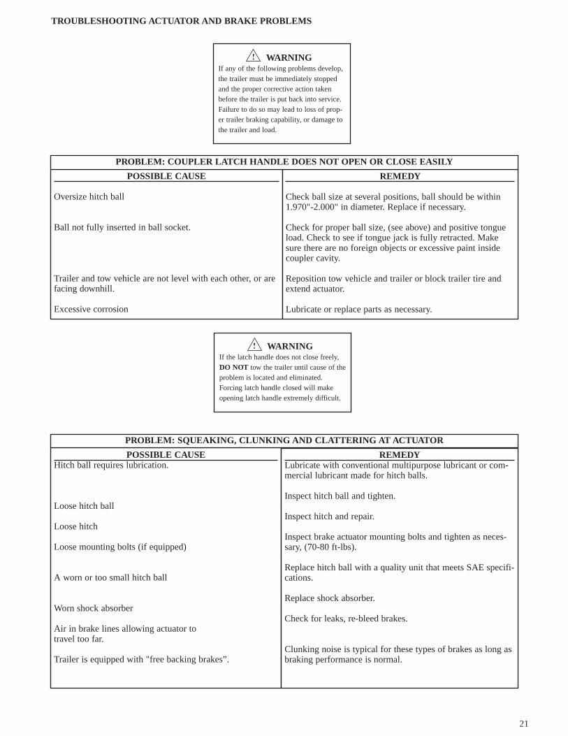
21
WARNINGIf any of the following problems develop,the trailer must be immediately stoppedand the proper corrective action takenbefore the trailer is put back into service.Failure to do so may lead to loss of prop-er trailer braking capability, or damage tothe trailer and load.
POSSIBLE CAUSE
Oversize hitch ball
Ball not fully inserted in ball socket.
Trailer and tow vehicle are not level with each other, or arefacing downhill.
Excessive corrosion
REMEDY
Check ball size at several positions, ball should be within1.970"-2.000" in diameter. Replace if necessary.
Check for proper ball size, (see above) and positive tongueload. Check to see if tongue jack is fully retracted. Makesure there are no foreign objects or excessive paint insidecoupler cavity.
Reposition tow vehicle and trailer or block trailer tire andextend actuator.
Lubricate or replace parts as necessary.
PROBLEM: COUPLER LATCH HANDLE DOES NOT OPEN OR CLOSE EASILY
WARNINGIf the latch handle does not close freely,DO NOT tow the trailer until cause of theproblem is located and eliminated.Forcing latch handle closed will makeopening latch handle extremely difficult.
TROUBLESHOOTING ACTUATOR AND BRAKE PROBLEMS
POSSIBLE CAUSEHitch ball requires lubrication.
Loose hitch ball
Loose hitch
Loose mounting bolts (if equipped)
A worn or too small hitch ball
Worn shock absorber
Air in brake lines allowing actuator to travel too far.
Trailer is equipped with "free backing brakes”.
REMEDYLubricate with conventional multipurpose lubricant or com-mercial lubricant made for hitch balls.
Inspect hitch ball and tighten.
Inspect hitch and repair.
Inspect brake actuator mounting bolts and tighten as neces-sary, (70-80 ft-lbs).
Replace hitch ball with a quality unit that meets SAE specifi-cations.
Replace shock absorber.
Check for leaks, re-bleed brakes.
Clunking noise is typical for these types of brakes as long asbraking performance is normal.
PROBLEM: SQUEAKING, CLUNKING AND CLATTERING AT ACTUATOR

22
Leaky hub grease seal. Replace grease seal and wheel bearings if damaged. Cleandrums and other hardware. Replace brake shoes if contami-nated with grease. Pack wheel bearings.
PROBLEM: GREASE LEAKING OUT BACK SIDE OF BRAKE DRUM OR ROTOR
Worn out shock absorber in actuator.
Loose hitch or hitch ball.
Not enough tongue weight or shocks on tow vehicle too soft.
Air in the brake lines.
Brakes out of adjustment.
Contaminated brake linings.
Replace the shock absorber.
Correct as necessary.
Correct as necessary.
Bleed the brake system.
Adjust the brakes property.
Fix cause of contamination (leaky wheel cylinder or hubgrease seal. Replace linings and clean braking surface ondrum or rotor.
PROBLEM: WHEN BRAKING, BRAKES REPEATEDLY COME ON AND RELEASE, BRAKING IS NOT SMOOTH.THIS CONDITION IS CALLED “CHUCKING”
POSSIBLE CAUSEWorn out brake shoes or disc brake pads.
Foreign material in the brake unit assembly.
Insufficient amount of hydraulic fluid
Broken lines or pinched line.
Seized actuator master cylinder. Prevents piston fromstroking.
Corrosion/rust keeps brake from operating.
Inadequate brakes for load or driving conditions.
REMEDYReplace brake shoes/pads on both sides of axles and checkdrums/rotors for wear or damage.
Clean thoroughly. Replace shoes and linings if contaminated.
Fill reservoir and bleed brakes. Check for leaks.
Replace faulty lines and bleed brakes.
Replace actuator master cylinder.
Replace damaged components or entire brake assembly asrequired.
If you have a tandem axis trailer add a second set of brakes.
PROBLEM: BRAKES DO NOT OPERATE, POOR BRAKE PERFORMANCE
Incorrect adjustment of drum brake.
Broken components in brake assembly.
Leaky or seized brake wheel cylinder.
Adjust all brakes.
Replace faulty parts and re-adjust brakes.
Replace/rebuild wheel cylinder and replace brake shoes (ifcontaminated with brake fluid). Clean drums and otherhardware, readjust brakes and bleed brake system.
DRUM BRAKES ONLY

23
POSSIBLE CAUSEDrum brake adjusted too tightly.
Disc brake caliper does not permit brake pads to release.
Leaky or seized brake wheel cylinder.
Damaged or frozen brake mechanism.
REMEDYReadjust, check all brakes.
Check caliper. Sections must be free to move apart. Iffrozen, remove and free up. Caliper piston may freeze upand prevent pads from retracting. Clean contaminants out ofpiston cavity. Replace piston, seal and protective dust bootBleed system.
Replace/rebuild wheel cylinder and replace brake shoes (ifcontaminated with brake fluid). Clean drums and otherhardware, readjust brakes and bleed brake system.
Rebuild or replace brake unit.
PROBLEM: ONE BRAKE OVERHEATING
Isolate the problem to actuator or the brakes as follows:
1. Fully extend actuator.2. Remove master cylinder reservoir plug.3. Check that reservoir is property filled.4. Manually push the actuator inner member in or use a screwdriver to stroke pushrod. (Be sure to depress the pushrod
release button after stroking pushrod).5. In the first 1/8" of stroke, the reservoir fluid will either remain dead calm or swirl around.
If the fluid swirls:Fluid is allowed to return to reservoir when actuator is extended.Actuator is functioning properly, troubleshoot brakes.
PROBLEM: BOTH BRAKES OVERHEATING
POSSIBLE CAUSEDrum brakes misadjusted.
Trailer stored with actuator compressed; rust has causedboth brakes to freeze up.
Check valve in master cylinder not properly punctured, (discbrakes only).
Inadequate brakes for towed load or driving conditions.
Pinches or kinks in brake lines.
REMEDYAdjust brakes properly.
Remove brakes. Clean, repair or replace components as nec-essary.
Puncture check valve. Re-bleed brake system.
If you have a tandem axle trailer add a second set of brakes.
Check brake lines and replace as necessary.
POSSIBLE CAUSE
Pulled breakaway cable, pushrod not reset
REMEDY
Reset breakaway cable, install clip.
It fluid does NOT move:Brake system is remaining pressurized and there is an actuator problem. Troubleshoot actuator.
For each of the following the actuator inner member must be removed. Follow the instructions in “DISMANTLING ANDASSEMBLY OF ACTUATOR”.
Fluid return hole in master cylinder clogged or misposi-tioned.
Corrosion in master cylinder freezing up piston or notallowing it to fully retract, usually caused by trailer storedwith actuator compressed.
Other malfunction or damage keeping the master cylinderfrom retracting.
Troubleshoot.Replace parts as necessary.

24
DISMANTLING AND ASSEMBLY OF ACTUATOR
DISMANTLING ACTUATORNote: Read and understand this section before attempting to disassemble inner member.
1. Extend actuator and remove cap from top.
2. Unscrew brake line fitting from rear of master cylinder. Note: Brake fluid escaping from master cylinder and brake linewill damage paint. Care should be taken to protect painted surfaces.
3. Remove one retaining ring and washer from each of the two roller pins located on side of actuator main body and slidepins out.
4. Pull on breakaway cable to remove inner member. This ensures that all components will come out attached together.Internal components can now be removed and dismantled for inspection, maintenance or repair. Entire inner member canbe replaced.
FIGURE 14 ACTUATOR, SIDE VIEW
ACTUATOR ASSEMBLY
Before the inner member can be inserted into the main body all internal components must be assembled and placed in theirproper position.
1. For ease of assembly, assemble inner member upside down.
2. Check that shock absorber, reservoir cover plate, diaphragm, and plug are assembled to the master cylinder.
3. Insert ball end of breakaway cable through hole in front of inner member, thread through latch assembly and around out-side of cable guide rod located on the side of master cylinder. Ball end of cable can now be inserted into hole on cableattachment plate and slid over into slot. Note orientation of cable attachment plate.
4. Insert square end of push rod assembly into hole in cable attachment plate. Insert round end of push rod assemblythrough rubber boot and into master cylinder piston.
5. Lightly grease rear rollers and hold them in the pockets in the sides of the master cylinder while inserting entire assemblyinto the inner member from the back end. While inserting assembly make sure push rod enters hole in push bracket. Thetab on the safety release bracket will have to be depressed to allow push rod assembly to fully enter hole in push bracket.The cable attachment plate should sit flush with the push bracket if properly assembled.
6. Make sure breakaway cable is correctly routed and is not wrapped around or hung up on any components.
7. While supporting the master cylinder, turn inner member assembly over and lightly grease front rollers and insert themthrough the openings on top of inner member. Note: Before inserting rollers make sure breakaway cable runs on top ofshock absorber eye ring.
8. Slide actuator inner member into outer member and line up roller pin holes on rear of actuator first. Insert lightly greasedroller pin.
9. Push or pull inner member to line up holes in rollers with hole in shock absorber eye-ring and insert lightly greased rollerpin.
10. Pull on inner member to the fully extended position. With slack taken out of breakaway cable, check that the cable clipis in place next to the indicator bead. Push up on safety release bracket tab to reset breakaway system.

25
11. Assemble washers and retaining rings on roller pins.
12. Connect brake line fittings and install cap.
13. Bleed brake system according to instructions outlined in “MANUAL BLEEDING OF THE BRAKE SYSTEM” sec-
tion. FIGURE 15 COMPONENT LOCATION (Inner Member)
MANUAL BLEEDING OF THE BRAKE SYSTEM
Check that all hydraulic fittings are secure. Read and understand all instructions before starting. Two people are required for manual bleeding.
1 . Remove the master cylinder reservoir plug and fill the reservoir with brake fluid. Use either DOT 3 or DOT 4 automotive brake fluid. Follow instruc-tions on brake fluid container. Avoid shaking brake fluid container and pour fluid slowly to minimize air entrapment. Let fluid in reservoir stand untilcompletely free of air bubbles.
2. IMPORTANT: Before bleeding brake lines, bleed the actuator master cylinder.Insert a screw driver through hole in bottom of inner member and use short strokes to pry on pushrod (while holding safety release bracket up) until noair bubbles are seen coming from small orificed hole in the bottom of the master cylinder reservoir.
3. Start bleeding procedure on the brake furthest from master cylinder.
4. At the brake assembly, connect a transparent bleeder hose to bleed screw fittingon wheel cylinder and submerge free end into a container partially filled with brake fluid. Do not reuse this fluid.
5. The first person strokes the pushrod slowly while holding safety release bracket up. The second person opens the bleed screw fitting. He then closes thebleed screw fitting BEFORE the first person SLOWLY releases the pushrod. Repeat this procedure until the fluid expelled from the bled hose is free ofair bubbles. Remember to always tighten the bleeder screw before releasing pushrod. During this procedure, the master cylinder reservoir fluid levelmust be maintained at no less than 1/2 full.
6. Repeat steps 4 and 5 for the other brake and the brakes on the front axle, if equipped with tandem brake axles.7. If installation is tandem axle with brakes on both axles, repeat bleeding procedure on rear axle brakes for the second time to assure purging of all air in
system.
BOTTOM VIEW
NOTE: ORIENTATION OF CABLE ATTACHMENT PLATE
IS TOWARD SIDE OF INNER MEMBER
CAUTIONIf you are not skilled in performing thefollowing procedures, have a qualifiedservice shop to perform the job.

26
8. As a final check after bleeding is completed, stroke pushrod and check to be sure brake system is pressurized by attempting to rotate a tire.9. Push up on the safety release bracket to ensure that pushrod is in released position.
10. After bleeding has been completed, re-check fluid level in master cylinder. Fill the master cylinder reservoir to indicator on reservoir plug. Do not over-fill.
IMPORTANT: DO NOT USE BRAKE FLUID DRAINED FROM BRAKE SYSTEM TO RE- FILL MASTER CYLINDER RESERVOIR AS SUCHFLUIDS CONTAIN CONTAMINANTS FROM SYSTEM WHICH MAY RESULT IN FAILURE IN BRAKE FAILURE OR COSTLY REPAIRS.
FIGURE 16 STROKING PUSHROD TO BLEED BRAKES
BREAKAWAY CABLE CLIP INSTALLATION INSTRUCTIONS
The breakaway cable clip is installed on the breakaway cable to prevent inadvertent pressurization of trailer brakes if cable is lightly pulled accidentally.Should the breakaway cable be pulled, during emergency situations, the clip will be destroyed. The breakaway system must be reset by pushing up on thetab located under coupler and the clip must be replaced.
To install clip, open latch handle and pull enough cable out of coupler body to make installation of clip easier. Clip must be installed on cable in front ofindicator bead as shown below.
Hold clip with pliers and insert over cable. Use a second set of pliers to gently close the opened end of clip. Clip should be free to move on cable.
CAUTIONThe breakaway system reset tab must bepushed up after clip installed and anytimethe cable has been pulled.

27
TWO YEAR LIMITED WARRANTYA-60 BRAKE ACTUATOR
The actuator is guaranteed against defects in materials and workmanship under normal use and servicefor a period of two years after the date of trailer purchase by the first owner.Limitations of Coverage
This warranty does not cover:Normal wear and tear, including corrosion.Damage caused by accidents, overload, abuse, modification or improper use of product.
This warranty is limited to defective parts replacement only. Charges for installing replacement parts,damage incurred to other equipment as well as incidental or consequential damages connected therewithare excluded.Some states do not allow the exclusion or limitation of incidental or consequential damages, so the abovelimitations may not apply to you.
Repair or Replacement ProcedureIf a failure or defect occurs during the warranty period, promptly contact warrantor's (UFP) customerservice department. Until such notice is received, warrantor will not be responsible for any repair orreplacement costs. UFP, at its option, may require return of the component in question to the factory,transportation charges prepaid. UFP will replace, FREE OF CHARGE, either the entire actuator assemblyor the part that proves defective, at its option. Any part found not to be defective will be returned freightcollect with an explanation.Installation of parts and adjustment of brake systems MUST be performed by a skilled brake mechanicand service manual instructions must be followed.
Vehicle Identification Number (VIN)The VIN is a 17 digit number located on the trailer identification label. The label is located on the left sideof the trailer. Be sure to include the VIN number in all communications with Warrantor.
Purchaser's RightsThis warranty gives you specific legal rights, and you may also have other rights which vary from state tostate.
Product ImprovementUFP has a policy of continuous product improvement. We reserve the right to change or improve thedesign of our products without assuming an obligation to modify any product previously manufactured.
135 Sunshine Lane • San Marcos, CA 92069(760) 744-1610 • Fax (760) 744-1616 • www.ufpnet.com

28
TRAILERING WITHDISC BRAKES
Disc brakes offer several advantages over drum brakes thatyou will appreciate. Disc brakes have improved resistanceto fade on downhill grades. They are self adjusting, so aspads wear, braking efficiency is not reduced. They recoverquickly after being submerged. They require less mainte-nance, are easier to flush out, and are less susceptible towater induced corrosion.
Your trailer's brakes are designed to energize automaticallywhen the tow vehicle's brakes are applied. These are knownas "surge brakes". When the vehicle slows down or stops,the forward momentum (surge) of the trailer against thehitch ball develops hydraulic pressure in a master cylinderinside the trailer brake actuator. Hydraulic lines are used totransfer pressure to the brakes and engage them.
Follow the tow vehicle manufacturer's guidelines withrespect to towing capability, hitch requirements, and othertowing considerations.
OPERATING TIPSCheck Your Brake System Before Each Trip1. Follow the pre-towing instructions that came with your
actuator.2. Make sure there are no leaks in the hydraulic system.3. A surface rust will build up on the rotor brake surface if
the trailer isn't used for a week or more. The brake padswill wipe off the rust in the first few miles of travel. If
Service Information for
the trailer has been idle for several months, or has beenfrequently submerged in salt water and the brakes notflushed out, severe corrosion can occur. Review themaintenance instructions in the following section.
When Starting Out1. The trailer should tow easily. If it seems hard to pull or
wants to swing toward one side, a rotor may not be rotat-ing freely. Investigate and solve the problem.
2. Try your brakes at slow to moderate speeds and developthe "feel" to sense they are functioning property.
On The RoadDrive carefully, obey speed limits and don't follow tooclosely. When towing a trailer, even with brakes, you willneed extra distance to stop. Allow for it.
On long, gentle downhill grades, try to avoid downshifting.Running in a low gear (which uses the engine as a brake)can actuate the trailer's surge brakes continuously for theduration of the grade, causing them to overheat. A betterprocedure is to slow down before the start of the down-grade run and maintain a controlled downhill speed withrepeated application and release of tow vehicle (and thustrailer) brakes. This technique permits the brakes to cooldown between applications. This will help ensure reservebraking capacity in an emergency.
On moderate and steep sections of road, downshifting intolower gears may be necessary and desirable to help controlspeed. Again, slow down before the grade and keep vehicle

29
speed under control. Do notstay on the brakes continuously because they can overheat.Don't hesitate to pull over when possible during or aftersevere braking situations to let everything cool down.
Running a stretch of highway where you don't brake is thequickest way to cool down the brake system because a highvolume of air flows thru the vented rotors and over thebrake pads to cool them.
It you decide that stopping capability is not what it shouldbe:1. Have the tow vehicle and trailer brakes checked for
proper operation.2. Review tow vehicle manufacturer's recommendations
and instructions for towing.3. If the trailer has only one set of brakes, consider adding
a second set.
Towing conditions, tow vehicle/trailer combinations imposemany variables. Make sure your outfit is safe and that youfeel comfortable with your particular circumstances beforeyou begin your trip.
Before LaunchingIf the brakes are hot, it is a good idea to let them cooldown. The sudden change in temperature when submergingvery hot calipers and rotors stresses all parts and couldcause damage.
Upon Return HomeIf you have been into saltwater, flush rotors and calipersthoroughly with fresh water to minimize subsequent corro-sion.
Back-up FeatureWe offer an electrically operated valve that is mounted onthe actuator and is connected to the tow vehicle back-uplights. Whenever they are energized, the valve opens andprevents pressure buildup in the system. Otherwise, youcould not back up. Most trailer manufacturer's use thisvalve.
If you try to back up and can't, check the valve. When it isenergized (by shifting into reverse) you can hear a notice-able "click" sound. If you don't, check for an electricalproblem.
StorageWhenever you park the trailer, make sure the actuator isfully extended. This position relieves pressure on thebrakes. Actuators sometimes freeze up in the compressedposition from corrosion. The next time out, the brakes willdrag and overheat.
ROUTINE MAINTENANCEHose Them OffIf you have been in saltwater, the single most importantmaintenance step for disc (or drum) brakes is to flush themthoroughly with fresh water.
Watch For CorrosionLight surface rust on rotors is common and not a problemas discussed elsewhere.
Extremely thick, heavy rust on rotor surfaces will not allowthe wheel assembly to rotate freely, resulting in heat build-up and premature wear on components. Clean or replacecomponents as necessary.
We recommend you check for rust damage at least annual-ly. More frequently if used in very humid environments, orin saltwater.
Pad WearPads must be replaced when 3/32" (.094") or less of thepad friction material is left.
Rotor DamageRotors should be resurfaced by a qualified brake specialistif extreme galling or wear marks are present.
Check pad and rotor condition at least annually.
Actuator and Hydraulic Line ServiceFollow actuator manufacturer's suggested service routine.Always be sure hydraulic fluid is clean. Be sure that fluidlevel is within 1/2 inch of top of reservoir. Do not fillbeyond that level. Brake systems use DOT 3 hydraulicfluid. Check for leaks in the brake lines and fittings. Leakswill lead to loss of trailer braking ability. Repair or replaceas necessary.
Replacement PartsAll replacement parts can be purchased from the trailermanufacturer or UNIQUE FUNCTIONAL PRODUCTS.Replacement pads, pistons and dust boots can also be pur-chased from auto part stores:
YEAR MODEL1997-2000 Kia Sephia
NOTE: Use only organic, non-metallic pads. Metallic padswill rust and depreciate rotor surface.
WARNINGIf you are not familiar with disc brake pad replacement,have this work performed by a qualified service shop.Improper pad replacement may decrease braking effec-tiveness, potentially causing an accident from not beingable to stop the tow vehicle combination within anacceptable distance.
WARNINGRotors must be replaced if the distance between brakesurfaces becomes less than 0.882" (22.4mm) for DB-42Model due to wear or machining. Otherwise, brakeeffectiveness and rotor integrity will be reduced resultingin loss of brakes.

30
TWO YEAR LIMITED WARRANTY
These disc brakes are guaranteed against failure attributable to rust or defects in materials and workmanship under normaluse and service for a period of two years after the date of trailer purchase by the first owner.
Limitations of Coverage
This warranty does not cover:
• Normal wear and tear.
• Damage caused by accidents, overload, abuse, modification or improper use of product.
This warranty is limited to defective parts replacement only. Charges for installing replacement parts, damage incurred toother equipment as well as incidental or consequential damages connected therewith are excluded.
Some states do not allow the exclusion or limitation of incidental or consequential damages, so the above limitations maynot apply to you.
Repair or Replacement Procedure
If a failure or defect occurs during the warranty period, promptly contact warrantor's (UFP) customer service department.Until such notice is received, warrantor will not be responsible for any repair or replacement costs. UFP, at its option, mayrequire return of the component in question to the factory, transportation charges prepaid. UFP will replace, FREE OFCHARGE, either the entire disc brake assembly or the part that proves defective, at its option. Any part found not to bedefective will be returned freight collect with an explanation. Installation of parts and adjustment of brake systems MUSTbe performed by a skilled brake mechanic and service manual instructions must be followed.
Vehicle Identification Number (VIN)
The VIN is a 17 digit number located on the trailer identification label. The label is located on the left side of the trailer. Besure to include the VIN number in all communications with Warrantor.
Purchaser's Rights
This warranty gives you specific legal rights, and you may also have other rights which vary from state to state.
Product Improvement
UFP has a policy of continuous product improvement. We reserve the right to change or improve the design of our productswithout assuming an obligation to modify any product previously manufactured.
135 Sunshine Lane • San Marcos, CA 92069760-744-1610 • Fax 760-744-1616 • www.ufpnet.com

31
DANGER
Before Towing
1. Check vehicle hitch, ball, and coupler for signs of wearor damage. Replace any parts that are worn or damagedbefore towing.
2. Know your trailer plus added load weight. Do notexceed lesser of coupler, vehicle, ball, or trailer weightratings. Use only the ball diameter indicated on yourcoupler. Use of any other ball diameter will create andextremely dangerous condition which can result in sepa-ration of the coupler and ball or ball failure.
3. Be sure the coupler is secured to the hitch ball and thelock lever or hand wheel is down tight and locked.
Clamp hand wheel couplers hand tight only. Assure thatthe ball clamp is properly nested under the ball and notsitting on top of the ball. Recheck tightness again aftertowing.
4. Check that trailer safety chains are properly connected.
5. Check that all trailer lighting is hooked up and workingcorrectly.
Recommended Maintenance
1. Smear ball socket and clamp face with chassis grease.Periodically oil pivot points and sliding surfaces of cou-pler with SAE 30 wt. motor oil.
2. When parking or storing your trailer, keep the coupleroff the ground so dirt will not build up in the ball socket.
COUPLER USE, MAINTENANCE, INSTALLATION, & SERVICE INFORMATIONAll Fulton Couplers Meet or Exceed SAE J684 and VESC V5 Specifications
FULTON Performance Products, Inc. P.O. Box 8 • Mosinee, WI 54455-0008
Weld on Instructions
• Use 1/8" fillet weld as shown below. Use No. E6011A.W.S. Welding Rod (AC RO DCAP) 1/8" Dia. Setmachine AMPS at 105/115 with 18/22 volts.
After installation is complete, check that coupler operationhas not been impaired in any way.
Bolt on Instructions
1. Assure coupler internal stop is butted against end oftrailer tongue for maximum overlap.
2. The preferred method is to use (4) 3/8" bolts throughside holes and torqued to 15/20 ft. lbs. (see illustrationbelow) An alternate method is to use (2) 3/8" grade 5through bolts and locknuts providing they can be torquedto at least 20 ft. lbs. without excessive deformation ofthe coupler or the trailer tongue.
Installation Instructions for Class 1 Couplers
CAUTION
F-1937 (C-7401) 3/01

32
Installation Instructions for Class 2, Class 3, and 34600/34318 Class 4 Couplers
Weld on Instructions
• Use 1/8" fillet weld as shown below. Use No. E6011A.W.S. Welding Rod (AC RO DCAP) 1/8" Dia. Setmachine AMPS at 105/115 with 18/22 volts.
After installation is complete, check that coupler operationhas not been impaired in any way.
Bolt on Instructions
1. Assure coupler internal stop is butted against end oftrailer tongue for maximum overlap.
2. The preferred method is to use (4) 1/2" bolts throughside holes and torqued to 30/35 ft. lbs. (see illustrationbelow) An alternate method is to use (2) 1/2" grade 5through bolts and locknuts providing they can be torquedto at least 35 ft. lbs. without excessive deformation ofthe coupler or the trailer tongue.
CAUTION
If housing is deformed, replace complete coupler. Use onlygenuine Fulton repair kits.
DANGER
When assembling the coupler make sure the ball clamp islocated properly onto the housing rivet as shown below foryour style of coupler.
DANGER
Adjustment method for Fas-Lok Couplers
With the assembled coupler clamped onto the correct sizeball, turn the locknut down just until the spring under thelocknut is fully compressed. Then back the locknut off 1/2to one turn or just enough to enable clamping or unclamp-ing the coupler and ball.
F-1937 (C-7401) 3/01
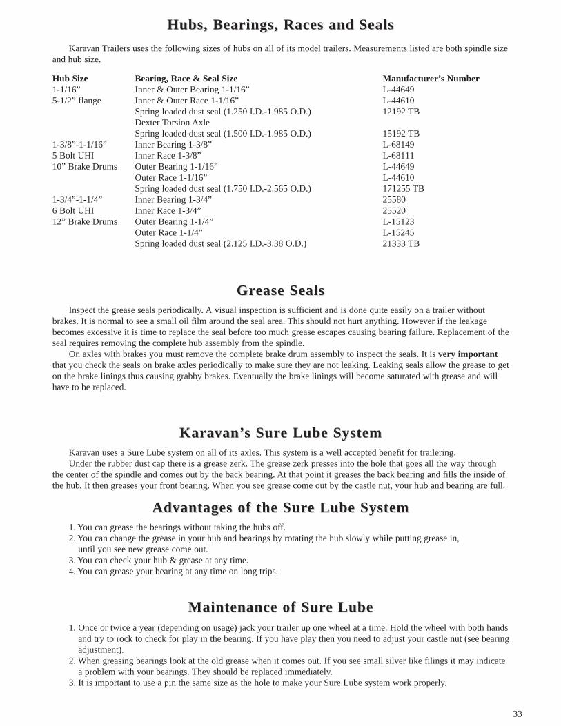
33
Karavan Trailers uses the following sizes of hubs on all of its model trailers. Measurements listed are both spindle sizeand hub size.
Hub Size Bearing, Race & Seal Size Manufacturer’s Number1-1/16” Inner & Outer Bearing 1-1/16” L-446495-1/2” flange Inner & Outer Race 1-1/16” L-44610
Spring loaded dust seal (1.250 I.D.-1.985 O.D.) 12192 TBDexter Torsion Axle Spring loaded dust seal (1.500 I.D.-1.985 O.D.) 15192 TB
1-3/8”-1-1/16” Inner Bearing 1-3/8” L-681495 Bolt UHI Inner Race 1-3/8” L-6811110” Brake Drums Outer Bearing 1-1/16” L-44649
Outer Race 1-1/16” L-44610Spring loaded dust seal (1.750 I.D.-2.565 O.D.) 171255 TB
1-3/4”-1-1/4” Inner Bearing 1-3/4” 255806 Bolt UHI Inner Race 1-3/4” 2552012” Brake Drums Outer Bearing 1-1/4” L-15123
Outer Race 1-1/4” L-15245Spring loaded dust seal (2.125 I.D.-3.38 O.D.) 21333 TB
Hubs,Hubs, BearBearings,ings, Races andRaces and SealsSeals
Inspect the grease seals periodically. A visual inspection is sufficient and is done quite easily on a trailer withoutbrakes. It is normal to see a small oil film around the seal area. This should not hurt anything. However if the leakagebecomes excessive it is time to replace the seal before too much grease escapes causing bearing failure. Replacement of theseal requires removing the complete hub assembly from the spindle.
On axles with brakes you must remove the complete brake drum assembly to inspect the seals. It is very importantthat you check the seals on brake axles periodically to make sure they are not leaking. Leaking seals allow the grease to geton the brake linings thus causing grabby brakes. Eventually the brake linings will become saturated with grease and willhave to be replaced.
GrGrease Sealsease Seals
Karavan uses a Sure Lube system on all of its axles. This system is a well accepted benefit for trailering.Under the rubber dust cap there is a grease zerk. The grease zerk presses into the hole that goes all the way through
the center of the spindle and comes out by the back bearing. At that point it greases the back bearing and fills the inside ofthe hub. It then greases your front bearing. When you see grease come out by the castle nut, your hub and bearing are full.
KarKaraavvan’an’s Surs Sure Lube Systeme Lube System
1. You can grease the bearings without taking the hubs off.2. You can change the grease in your hub and bearings by rotating the hub slowly while putting grease in,
until you see new grease come out.3. You can check your hub & grease at any time.4. You can grease your bearing at any time on long trips.
AdAdvvantaantagges of the Sures of the Sure Lube Systeme Lube System
1. Once or twice a year (depending on usage) jack your trailer up one wheel at a time. Hold the wheel with both handsand try to rock to check for play in the bearing. If you have play then you need to adjust your castle nut (see bearingadjustment).
2. When greasing bearings look at the old grease when it comes out. If you see small silver like filings it may indicatea problem with your bearings. They should be replaced immediately.
3. It is important to use a pin the same size as the hole to make your Sure Lube system work properly.
Maintenance of SurMaintenance of Sure Lubee Lube

34
WWhenhen to Checto CheckkTrailers often sit idle for extended periods of time so it is a good idea to check all of these before any use. Bearings
rechecked and repacked before storage and after immersion in salt water will last longer.Check the lubricant level when the hub is warm. On boat trailers, we suggest that you check just prior to launching to
be sure the hub is full of grease when the axle is submerged.
RecommendedRecommended LubrLubricanticantChevron RPM Automotive LC #2 Grease is installed at the factory. Any good marine grade water-resistant grease is
recommended. Different types of grease shouldn’t be mixed.
BearBearing Reing RepacpackingkingIdeally, one would not have to be concerned about wheel bearings in that you would not have to get them submerged
in the water when loading and unloading. This is not the case in many instances so therefore preventative maintenance isrequired. This type of maintenance varies so greatly because one individual may back his trailer in and out of the water300 times a year and tow it 1,500 miles total while another individual may back his in the water six times a year but tow it7,000 miles. Then we also have an individual that hauls his boat 30 miles, puts it in the water for the summer, and thenloads it back up in the fall for the 30 mile trip home.
Because of the various types of ways in which people use a trailer it becomes difficult to say every 500 miles repackyour bearings of after backing in the water 10 times repack your bearings. Neither of the above can apply.
About the only thing that applies is good common sense.Note the following:1. When water gets in the bearings and is on the steel itself it will rust. So the most important part is get a good grade ofwheel bearing grease that will not break down when water is mixed with it.2. Pack the bearings by forcing the grease into all the small cavities in the bearings. Fill the cavity in the hub with grease.3. Make sure the grease seals are in usable condition.4. Keep the bearings and grease free of any dirt or foreign matter.5. The wheel bearings should be repacked anytime during the year that you plan on storing the trailer for a period of time.6. The more often you back your trailer in the water, the more chance you stand of getting water in the bearings. Youshould definitely be packing your bearings more often (at least twice during the season) if this is the situation.7. Towing a trailer numerous miles has its good points and bad points. Long towings may warm the hub and grease upenough to remove any water it may have collected. However should you then back the warm hubs into the water just aftera long tow they will take on water through condensation. It is therefore important that you let them cool before backinginto the water.8. Be sure the bearings are adjusted properly not too tight, or too loose. See Bearing Adjustment.
Check the grease in your hubs once a year. In most instances, if a good quality lubricant is used and the lubricant lev-els are maintained, it may not be necessary to repack the bearings. However, should the grease appear to be contaminatedor broken down, remove all of the old grease from the bearings and hubs and completely repack. Remove the rear bearingwill most likely cause damage to the rear seal. A new one should be installed when reassembling.
BearBearing ing AdjustmentAdjustmentThe wheel bearings have been preadjusted at the factory. To maximize bearing life, however, we suggest that you
check the bearing adjustment after the first 50 miles of use, then every time the bearings are repacked.Bearing adjustment can be checked by jacking up one side of the trailer. Grip the edge of the wheel and see if you can
rock it or move it. If you have movement remove the dust cap and the cotter key. While rotating wheel tighten the spindlenut to a recommended 20 inch-pounds of torque if your trailer has 1-1/16" - 1-1/16" bearings or 30 inch-pounds if yourtrailer has 1-3/8" - 1-1/16" bearings. Do not over tighten. Look for the hole in the spindle through the slots in the spindlenut. If you can see any part of the hole through the slot in the nut turn the nut counterclockwise until the next slot in thenut lines up with the cross hole. Insert cotter key or new L pin.
If you cannot see any portion of the hole in the spindle through the slots in the nut, turn the nut counterclockwise untilthe hole lines up with the first slot available in the nut. Insert cotter key or L pin.
This adjustment will give you from one-thousandths to ten thousandths end play, which is in tolerance for properadjustment. Check wheel again for the movement. If no movement, spin wheel. Wheel should turn easily and have no endplay (lateral movement). Bend ends of cotter key or L pin to keep it from coming off. A large cotter pin must be used to fillthe hole for the sure lube system to work properly. Position dust cover. Tap lightly on edges to start cover. Then using ascrewdriver and alternating sides as you work around the dust cover, tap screwdriver with hammer until the dust cover iscompletely into the hub and the flange on the dust cover is tight against the hub face. Repeat on other wheels.
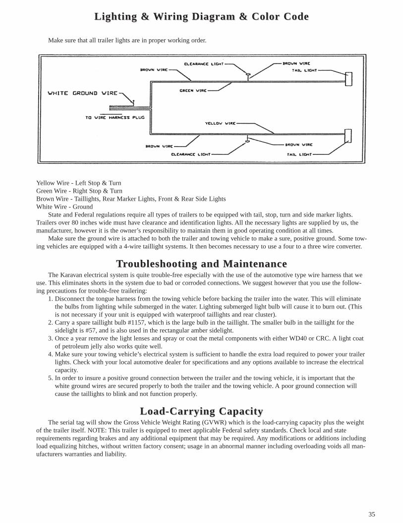
35
Lighting & Lighting & WWiriring Diaing Diaggrram & Color Codeam & Color Code
Make sure that all trailer lights are in proper working order.
Yellow Wire - Left Stop & TurnGreen Wire - Right Stop & TurnBrown Wire - Taillights, Rear Marker Lights, Front & Rear Side LightsWhite Wire - Ground
State and Federal regulations require all types of trailers to be equipped with tail, stop, turn and side marker lights.Trailers over 80 inches wide must have clearance and identification lights. All the necessary lights are supplied by us, themanufacturer, however it is the owner’s responsibility to maintain them in good operating condition at all times.
Make sure the ground wire is attached to both the trailer and towing vehicle to make a sure, positive ground. Some tow-ing vehicles are equipped with a 4-wire taillight systems. It then becomes necessary to use a four to a three wire converter.
TTrrouboubleshooting and Maintenanceleshooting and MaintenanceThe Karavan electrical system is quite trouble-free especially with the use of the automotive type wire harness that we
use. This eliminates shorts in the system due to bad or corroded connections. We suggest however that you use the follow-ing precautions for trouble-free trailering:
1. Disconnect the tongue harness from the towing vehicle before backing the trailer into the water. This will eliminatethe bulbs from lighting while submerged in the water. Lighting submerged light bulb will cause it to burn out. (Thisis not necessary if your unit is equipped with waterproof taillights and rear cluster).
2. Carry a spare taillight bulb #1157, which is the large bulb in the taillight. The smaller bulb in the taillight for thesidelight is #57, and is also used in the rectangular amber sidelight.
3. Once a year remove the light lenses and spray or coat the metal components with either WD40 or CRC. A light coatof petroleum jelly also works quite well.
4. Make sure your towing vehicle’s electrical system is sufficient to handle the extra load required to power your trailerlights. Check with your local automotive dealer for specifications and any options available to increase the electricalcapacity.
5. In order to insure a positive ground connection between the trailer and the towing vehicle, it is important that thewhite ground wires are secured properly to both the trailer and the towing vehicle. A poor ground connection willcause the taillights to blink and not function properly.
Load-CarLoad-Carrrying Caying CapacitypacityThe serial tag will show the Gross Vehicle Weight Rating (GVWR) which is the load-carrying capacity plus the weight
of the trailer itself. NOTE: This trailer is equipped to meet applicable Federal safety standards. Check local and staterequirements regarding brakes and any additional equipment that may be required. Any modifications or additions includingload equalizing hitches, without written factory consent; usage in an abnormal manner including overloading voids all man-ufacturers warranties and liability.
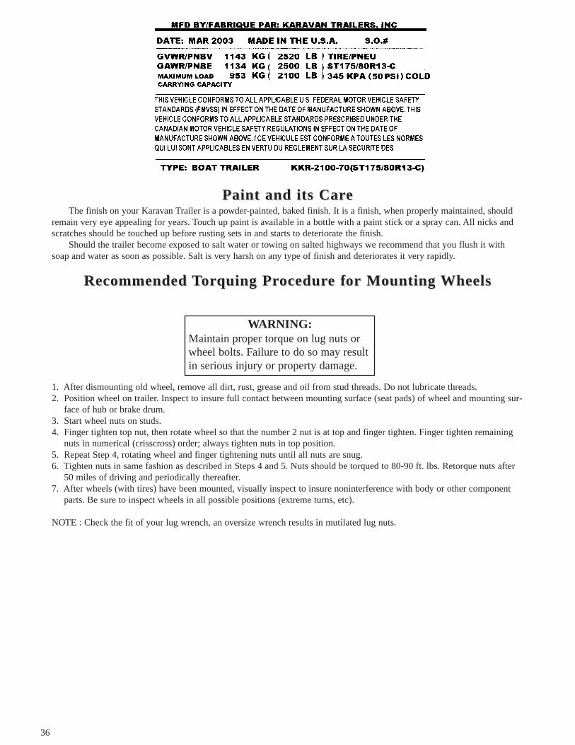
36
PPaint and its Caraint and its CareeThe finish on your Karavan Trailer is a powder-painted, baked finish. It is a finish, when properly maintained, should
remain very eye appealing for years. Touch up paint is available in a bottle with a paint stick or a spray can. All nicks andscratches should be touched up before rusting sets in and starts to deteriorate the finish.
Should the trailer become exposed to salt water or towing on salted highways we recommend that you flush it withsoap and water as soon as possible. Salt is very harsh on any type of finish and deteriorates it very rapidly.
Recommended Recommended TTororquing Prquing Procedurocedure fe for Mounting or Mounting WWheelsheels
1. After dismounting old wheel, remove all dirt, rust, grease and oil from stud threads. Do not lubricate threads.2. Position wheel on trailer. Inspect to insure full contact between mounting surface (seat pads) of wheel and mounting sur-
face of hub or brake drum.3. Start wheel nuts on studs.4. Finger tighten top nut, then rotate wheel so that the number 2 nut is at top and finger tighten. Finger tighten remaining
nuts in numerical (crisscross) order; always tighten nuts in top position.5. Repeat Step 4, rotating wheel and finger tightening nuts until all nuts are snug.6. Tighten nuts in same fashion as described in Steps 4 and 5. Nuts should be torqued to 80-90 ft. lbs. Retorque nuts after
50 miles of driving and periodically thereafter.7. After wheels (with tires) have been mounted, visually inspect to insure noninterference with body or other component
parts. Be sure to inspect wheels in all possible positions (extreme turns, etc).
NOTE : Check the fit of your lug wrench, an oversize wrench results in mutilated lug nuts.
WARNING:Maintain proper torque on lug nuts orwheel bolts. Failure to do so may resultin serious injury or property damage.

37
ChangChanging ing TTirireeIt is desirable that you carry a jack that will work on your trailer in the event that you have a flat tire. A small board or
block can also be very beneficial in the event you are jacking on soft dirt or hot asphalt. the jack (depending on style) maybe placed under the side frame in back of the wheel or also under the axles.
SafSafety Chainsety Chains
The safety chains on your unit are an added insurance that it will not become detached from the towing vehicle. Your trailerhitch on the towing vehicle should have two holes or rings for fastening the safety chains, preferably one on each side ofball hitch. It is strongly recommended that you crisscross the chains under the tongue, the chain on the left side of the trailerattached to hole or ring on the right side of the ball hitch, and vice versa. This prevents the trailer tongue from dropping tothe road should the coupler or ball hitch fail. The chains should be rigged as tight as possible with just enough slack toallow tight turns to be made. This can be accomplished by twisting the chain hook in a clockwise or counterclockwisedirection thus twisting the link spacings and making the chain shorter. Also by keeping your chains as short as possible youprevent them from dragging on the road and wearing the chain links. NOTE: If for any reason you find it necessary toreplace a safety chain, do not use or substitute any lighter weight chain than supplied with your trailer. All chain attach-ments such as hooks, s-hooks, etc. must be equally as strong as the chain itself.
TTie Doie DownswnsIt is very important that your recreational vehicle is supported properly by the trailer. It is also important that your
recreational vehicle stays positioned on the trailer while towing. This is accomplished by securing your load to the trailer bysome type of tie down.
CAUTION:Avoid sharp turns. This could bend,create extreme stress or fracture eitherthe coupler or the trailer tongue.
Trailer Trailer Weight GVWR in Minimum Braking Strength in PoundsClass PoundsII 1,000 to 3,500 3,500III 3,500 to 5,000 5,000IV 5,000 to 7,600 7600V 7,600 to 16,200 16200

38
1 Bow Tie Down: Karavan Trailers offers one of the best winch post assemblies as far as adjustment and stability areconcerned. However for added security, you may want to use a separate tie down to tie the bow eye both downward and alsoforward. This should guard against any sudden stops or starts. This also guards against winch or winch strap failure (onBoat Trailers).
2 Rear Tie Down: It is very important that the transom of your boat is resting fully and securely on the supports pro-vided and that it remains that way while trailering. The two most common types of tie downs are the transom tie down strapor else the gunwale tie down. Either system works well and holds your boat solidly on the trailer. Places to fasten the gun-wale tie downs are provided in either the light brackets or the side frame brackets (on Boat Trailers).
TTirires & es & TTirire Pre PressuressureeThe most common cause of trailer tire trouble is under-inflation. It is important therefore that you always maintain full
air pressure, as indicated by the tire manufacturer on the tire’s sidewalls or on the trailer manufacturer’s certification label.Always check air pressure when the tires are cold, before you’ve moved the trailer. Tires heat up and the air pressure
increases after traveling only a short distance.When your trailer tires become worn or damaged, replace them promptly with the same type, size and capacity (not
necessarily the same brand) as the original tires, For example: some trailers are not designed for use with radial tires. If theoriginal tires on your trailer were not radials, do not replace them with radials (radials can be used as long as they have theproper carrying capacity).
For safety and convenience, it is recommended that you always carry a spare wheel and tire. Check your state laws inregards to spare wheels, most states require you to carry a spare at all times.
Most tire manufacturers have the air pressure molded on the tire sidewall. Listed below are the tire sizes with theirrespective carrying capacities and tire pressures.
Bias-PlBias-Ply y TTirireses
Radial Radial TTirireses
ImporImportanttantMany tire manufacturers have toll free numbers, which you may call should you have a problem with one of their products.(See inside front cover).
Tire Size Load Range Ply Rating Max Load lbs. Inflation P.S.I. Cold4.80 x 8 B 4 590 60
4.80 x 12 B 4 780 604.80 x 12 C 2 990 90
5.30 x 12 B 2 835 555.30 x 12 C 2 1045 805.70 x 8 B 2 715 505.70 x 8 C 3 910 75
ST175/80D B 2 1100 35ST175/80D C 6 1360 50ST205/75D B 2 1430 35ST205/75D C 6 1760 50ST215/75D C 6 1870 50ST225/75D C 6 2150 50ST225/75D D 6 2540 657.50 x 16 E 6 2780 7516.5 x 8 B 2 620 4518.5 x 8 B 2 770 3518.5 x 8 C 4 940 50
20.5 x 8.0 x 10 C 4 1105 5020.5 x 8.0 x 10 E 5 1535 90
Tire Size Load Range Ply Rating Max Load lbs. Inflation P.S.I. coldST175/80R C 6 1360 50ST205/75R C 6 1760 50ST215/75R C 6 1870 50

39
LIMITED WARRANTYHIGHWAY / NON-HIGHWAY TIRE & WHEEL WARRANTY
Carlisle Tire & Wheel Company (“Carlisle”) warrants, subject tothe terms, conditions and limitations stated herein, tires & wheels to befree from defects in materials and workmanship.
Carlisle’s liability for tires and wheels shall be limited to replace-ment of any defective tire or wheel plus any applicable taxes.
Carlisle’s Warranty1. The Carlisle Tire & Wheel Warranty (“Warranty”) applies only to the
original purchaser for two years from the date of purchase.a) The warranty period for the coating of the wheel is ninety (90) days
from the date of purchase.
2. The Warranty is void if the tire or wheel fails due to damage fromimproper inflation pressures, exceeding the maximum speed limit, oroverloading the tire beyond the maximum load capacity stated on thesidewall.
3. The Warranty does not cover incidental or consequential damagesincluding, but not limited to, lost time, inconvenience, loss of vehicleuse, cost of towing or transportation, related property damage or conse-quential damages of any type or nature.
4. The Warranty does not cover mounting and balancing charges.
5. The Warranty is void if a covered tire is worn past last 3/32 of treaddepth at any point on the tread contact surface.
6. The Warranty does not apply to the following:a) repaired tubes, tires or wheelsb) tires or wheels used in racing and competitionc) tires or wheels subjected to road hazards, overloading, underinfla-
tion, improper mounting, fitment to incorrect rim, purposeful abuseor chemical contamination
d) tires or wheels which have been patched, unplugged or repaired orinto which liquid balancers or sealants have been introduced
e) cosmetic irregularities
7. Carlisle makes no expressed claims of expected tire wear. Variables thataffect tire wear are driving conditions, load and tire inflation pressure.
To obtain warranty adjustments or warranty information contact yourCarlisle dealer or call Carlisle’s Product Services Department at 1-800-260-7959 or fax to 1-800-352-0075. Claims must be made within 30 daysof discovery of irregularity. Carlisle reserves the right to inspect all prod-ucts before making adjustments.
THERE ARE NO WARRANTIES EITHER EXPRESSED OR IMPLIED,INCLUDING THE IMPLIED WARRANTIES OF MERCHANTABILITYAND FITNESS FOR A PARTICULAR PURPOSE, WHICH EXTENDBEYOND THE DESCRIPTION ON THE FACE HEREOF. CARLISLESHALL NOT BE LIABLE FOR ANY INCIDENTAL OR CONSEQUEN-TIAL DAMAGES. NO REPRESENTATIVE OF CARLISLE TIRE &WHEEL COMPANY HAS AUTHORITY TO MAKE ANY REPRESEN-TATIONS OR PROMISES EXCEPT AS STATED HEREIN.
Some states do not permit limitations on the period of time animplied warranty lasts and do not permit the exclusion of limitation ofincidental or consequential damages, thereof, the above limitations orexclusions may not apply. This warranty provides specified legal rights.Other rights may vary from state/province to state/province.
NOTE: All specifications subject to change without notice.
Carlisle Tire & Wheel Company25Windham BoulevardAiken, South Carolina 29805
Rev. 4/01
THE LOADSTARWORRY FREE WARRANTY
FOR HIGH SPEEDTRAILER TIRES
EligibilityYou are eligible for the benefits of this policy if you
are the owner and original consumer of new LOADSTARtires, bearing Dept. of Transportation prescribed tire identi-fication numbers, only on the vehicle on which they wereoriginally installed according to the vehicle manufacturer’sor LOADSTAR recommendations.
What is Warranted and for How LongYour tires are warranted against failures due to defec-
tive materials and workmanship.(A) Tires are eligible for warranty if presented not more
than four years past manufacturing date and has aminimum of 2/32nd" tread remaining.
(B) Free Replacement For (Bias or Bias/Belted) HighSpeed Trailer Tires. If a LOADSTAR tire fails due todefective materials or workmanship during the first10 % of treadwear, or the first year, the tire will bereplaced with a new comparable LOADSTAR tirewithout charge.
(C) Treadwear Prorated Replacement. Tires not qualify-ing for free replacement will be replaced with a new,comparable tire based upon the percentage of treadthat has been worn. The price you pay will equal thepercentage of original, usable tread worn, multipliedby our then current “Predetermined AdjustmentPrice”. Owner pays mounting charge.
Definition of Comparable TireA “comparable” new LOADSTAR tire may either be
the same line of tire, or, in the event the disabled tire is outof production or unavailable, the same basic or equal con-struction and quality with different sidewall or treadwearconfiguration. If a higher priced tire is accepted as replace-ment, the difference in price will be paid by the owner.
Computing TreadwearTreadwear is computed as a percentage of the original,
usable tread. The original, usable tread does not include thelast 2/32nd inch of tread depth.
What is Not Covered By The Warranty• Failure due to fire, accident, malicious mischief,
improper inflation, improper use, running flat, over-loading or road hazards. Examples of road hazardsinclude nails, glass and other foreign objects and natu-ral and man-made defects or obstacles such as excava-tions, construction, potholes and chuckholes. Damagescaused by road hazards include cuts, snags, punctures,scuffs, carcass bruises and impact breaks.
• Premature or irregular wear due to improper inflationor alignment or balance.
• Tires presented by other than the original consumer.

40
• Tires with weather cracking which were purchasedmore than (4) four years prior to presentation foradjustment. If you have no proof of purchase date, tiresmanufactured (4) four years prior to presentation arenot covered.
• Loss of time, inconvenience, loss of use of the vehicle,costs of towing or transportation, or consequential dam-ages of any type or nature.
• Any implied warranty, including merchantability or fit-ness, is limited to the duration of this written warrentyor (4) years, whichever is less.
• Balancing or mounting charges.
*NOTE: This limited warranty is the entire warrantygiven by LOADSTAR and LOADSTAR’s complete obliga-tion is as set forth herein. No one has authority to imply,suggest, agree, represent, warrant or promise contrary tothe terms hereof.
Owner’s ObligationYou must present the tire to any LOADSTAR Tire
Distributor or participating dealer in the U.S.A. To obtainno charge adjustment for tires, you must present proof ofpurchase date (such as trailer dealer or tire retailer invoice).You are responsible for payment of all taxes, as well asretailer charges for services that you request but are notcovered by the warranty. This warranty gives you specificlegal rights and you may also have other rights which varyfrom state to state.
NOTE:Some states do not allow the exclusion or limitation of
incidental or consequential damage or how long an impliedwarranty lasts, so the limitations or exclusion may notapply to you.
Adjustment ProceduresUnserviceable LOADSTAR tires adjustable under the
terms of this policy should be returned to a LOADSTARtire Distributor.
1.) Check National Distributor Directory for the near-est LOASTAR Tire Distributor. Call the nearest dis-tributor. They can tell you where the nearest dealerwould be located.
2.) Call 1-(800)-225-4714, 9AM-5PM weekdays forthe nearest distributor.
If There is No LOADSTAR TireDealer Available
1.) Purchase a tire of like quality and price.
2.) Return the LOADSTAR tire to the nearest distributioncenter, UPS. collect.
3.) IMPORTANT – You Must include the following:A.) Invoice for replacement
B.) Original invoiceC.) Current information
Name: _ _ _ _ _ _ _ _ _ _ _ _ _ _ _ _ _ _ _ _ _ _ _ _ _ _ _
Address: _ _ _ _ _ _ _ _ _ _ _ _ _ _ _ _ _ _ _ _ _ _ _ _ _ _
Phone Number: _ _ _ _ _ _ _ _ _ _ _ _ _ _ _ _ _ _ _ _ _ _
Date Tire Removed: _ _ _ _ _ _ _ _ _ _ _ _ _ _ _ _ _ _ _ _
Reason Removed: _ _ _ _ _ _ _ _ _ _ _ _ _ _ _ _ _ _ _ _ _
Trailer Make: Model : Year:
________________________________________________
4.) Fill out this information and tape securely to the tirealong with a mailing label addressed to the distributor.
5.) When the LOADSTAR Distributor receives the tire hewill examine it, adjust it under the terms of the LOAD-STAR warranty and send you a complete explanationand check (if applicable).
Important Safety InformationAny tire, no matter how well constructed, may fail due
to improper maintenance or service factors, creating a riskof property damage and serious or fatal injury. For yoursafety, comply with the following:
1.) Check air pressure monthly when tires are “cold”.Use an accurate tire air pressure gauge. Do notreduce pressure when tires are hot.
Proper inflation is essential. Underinflation producesflexing of sidewalls and builds up heat to the point thatpremature tire failure may occur. Overinflation cancause the tire to be more susceptible to impact damage.
2.) Never overload your tires. The maximum loadcapacity and maximum inflation pressure are mold-ed into the sidewall of your tire. Overloading buildsup excessive heat and can lead to early tire failure.
3.) Avoid damaging objects (chuckholes, glass, rocks,curbs, etc.) which may cause internal tire damage.Continued use of a tire that has suffered internaldamage, which may not be visible externally, canlead to dangerous tire failure. Determination ofinternal damage will require dismounting of the tireand examination by trained tire personnel.
4.) Property damage and serious or fatal injury can alsoresult from the following causes:
• Improper tire mounting and inflation procedures maycause the tire beads to break with explosive force dur-ing installation of the tire on the rim. Tire and rimmust match in size. Rim parts must match by manu-facturer’s design. Clean rim. Lubricate rim and beads.Do not exceed the maximum recommended pressureto seat the beads. ONLY SPECIALLY TRAINEDPERSONS SHOULD MOUNT TIRES.
• Use of worn out tires (less than 2/32nd" remainingtread depth) increases the probability of tire failure.
• Excessive speed creates heat buildup in a tire, leadingto possible tire failure.

41
TToowing wing YYour our TTrrailerailerCaution!
Check the following items each time before towing trailer.1. Be sure all parts, bolts and nuts are tight. 6. Do not exceed trailer capacity.2. Secure load to trailer with BIA approved 7. Be sure all lights are operating and are disconnectedtiedowns. before backing into water.3. Check tire pressure when tire is cold. Check 8. Coupling ball - make sure you are using the sizeand adjust wheel bearings if necessary after marked on the trailer coupling and coupling must befirst 50 miles of use. securely latched to the ball.4. Inspect and repack wheel bearings at least 9. Cross safety chains under tongue and secure to twice a year and before storing. towing vehicle.5. Check that the Bed Locking Pin is in place. 10. Check brake operation.
LauncLaunchinghingWhile you are waiting for your turn at the ramp, you should prepare your boat for launching. Attach a bow line to your
boat and detach trailer tie-downs. If your boat is an outboard or stern drive, tilt up the lower unit. To avoid flooding andswamping your boat, before launching be sure the hull drain plug is in place and tight.
BacBack k TTrrailer to the Rampailer to the RampHave someone stand to one side of the ramp to direct you. Backing up a trailer can be tricky. A good way to simplify
the procedure is to grasp the steering wheel with one hand at its lowest point (at 6 o’clock). When you want the trailer to goright, move your hand on the wheel to the right; to make the trailer go left, move your hand to the left.
LauncLaunchinghingBack your trailer into the water until the front step of fender is at water level. This is a water level guide, which you can
use on most ramps, however on extremely flat ramps you will want to back in further. On steeper ramps you will not wantto back in as far. The other controlling factor is the style boat you have. Experimenting at this point will give you the bestconditions for launching and loading your boat.
Set parking brake and gear shift. Unlock winch and push boat slowly but firmly off the trailer into the water. Be sureyou (or your partner) have a firm hold on the bow line.
A more controlled launching can be achieved by letting you boat roll off the trailer with the winch rope attached. Thisis a slower process of unloading but is definitely more controlled.
Loading yLoading your Boaour BoattAgain, back the trailer into the water following the same instructions as just stated for launching.
1. Prepare your boat for winching on the trailer. Bring your boat over to the trailer with the mooring rope. With thewinch in the neutral lock position grab the winch rope and unwind the winch, Hook winch rope into eyelet on boat.Place winch latch into lock position for cranking boat on trailer. Winch slowly at first giving the boat time to swingaround into position. This is necessary especially with a cross-current or cross wind. Crank boat completely ontotrailer. Hook bow eye safety chain.
2. Some boaters prefer to drive their boats on the trailer. One thing to keep in mind is that you should not back into thewater too deep. If you are in too deep the trailer looses all of its centering capabilities because your boat is floatingon the water above the trailer. Loading your unit several times will give you a better feel for the depth to back yourtrailer in.
Drive your boat on carefully and try to hit the center of the trailer as much as possible. If you do not hit the centerof the trailer, just keep slight pressure on the boat at slow throttle and drive the boat like you would a car. If you do nothit the center of the trailer, turn your boat so the front will go to the right, reverse the procedure if you are to the left ofcenter. Keep turning until you feel the boat slide or drop into the center. Line the front of the boat up so it is headedright into the bow stop on the winch stand, adjusting it by turning the rear of your boat like a car.

42
FULTONMarine Trailer Jack Owner’s Manual
WARNING• Read and understand all instructions before installing and/or using product. NEVER allow anyone unfamiliar with the operating instruc-
tions to use this product.• Read and understand all instructions provided by the manufacturer of the products(s) that this jack will be installed on.• Installation of these Fulton jacks must conform to the following mounting instructions only.• Fulton is not responsible for accidents, occurrences, injuries and losses to or of any person or property wherever which arises as a result
of Purchaser’s alterations, modifications, assembly, reassembly, or installation of this product.• When cranking jack or coupling trailer, secure trailer from rolling.• These jacks are designed for vertical loading, excessive side forces must be avoided• Refer to product to obtain rated capacity. If uncertain contact Fulton Performance Products.• These jacks are designed for mounting to square or rectangular trailers only. Theses jacks are not intended for mounting to trailers with
round tongues.• Assure the correct mounting hole pattern is for your trailer tongue size. The gap between the mounting bolts and the trailer tongue is not
to exceed 1/16"• In both the vertical and horizontal positions, the plunger must be positioned in the detent hole in the mounting bracket.• When manually moving trailer over rough or unpaved surfaces, crank to lowest practical position to minimize bending stress on jack.• Operator use caution never to position any part of your body under any portion of the jack or the load being supported. Disregard could
cause property damage and/or serious bodily injury.• Inspect snap ring groove and remove any coating or foreign material from the groove before inserting snap ring. Make sure snap ring is
properly seated in the groove before each use.• Make certain that the plunger pin is properly locked into the detent hole in the mounting bracket before raising of lowering the trailer
tongue.• When manually moving trailer over rough or unpaved surfaces, crank to lowest practical position to minimize bending stress on jack.• Do not attempt to weld “bolt-on” brackets or straps to the trailer. These items are zinc plated and will emit toxic fumes when welded.
Special brackets are available for “weld-on” applications.• Failure to follow these warnings and instructions may result in property damage and/or serious bodily injury.
PerformanceProducts
MOUNTING INSTRUCTIONSBefore mounting your trailer jack, check for interference from recessed ball mounts, trailer coupler, hitch or hitchplates and/or vehiclebumper. Rotate the jack handle to check that the swing is not obstructed. If the jack is of the swing-away or swivel design, check the unitin both vertical and horizontal positions. When the swing-away jack is in the horizontal or storage position, there should not be any inter-ference from structural members of the trailer or trailer coupler. On all jacks check that proper ground clearance has been achieved andwill not contact the towing vehicle when in a tight turn. If the jack is not installed correctly, any interference (steep inclines, angled turnsetc.) may cause non-repairable damage to the jack and/or trailer. After installation is complete, check that jack operation has not beenimpaired in any way.
Bolt-On Mounting Instructions (Fig 1 - Illustration shown is for a 3" or 4" high trailer frame. If trailer has a 5" frame, mount bracketrotated 90 degrees)
1) Place the jack against the trailer tongue and positions the mounting straps (A) on the opposite side of the tongue. Place the straps sothe flat side is against the tongue. Make sure the holes in the bracket and straps are in line.
2) Insert the four bolts (B) through the bracket and straps (two bolts on the top of the tongue and two below the tongue). Position the jackso the at the top bolts rest directly on the top of the tongue and the bottom bolts are as close to the tongue as possible. The gapbetween the mounting bolts and the trailer tongue is not to exceed 1/16".
3) Secure with locknuts (C). Torque the nuts to 25 ft-lbs.4) Check for clearance of handle swing, trailer light cables, and coupler clearance.
Weld-On Mounting Instructions - Fig 2 (Bracket shown is a snap ring style. Bolt-thru style will be orientated and welded the same.)
1) All welding operations must be performed by an AWS certified welder.2) Place the weld-on mounting plate, Item #27 or #44, against the trailer tongue with the flange locating against the bottom and weld as
shown in Fig 2, using four 1" long, 3/16" fillet welds.3) Snap Ring Style - Assemble the jack to the mounting plate by placing the jack over the grooved extruded opening on the mounting
plate. Fasten by placing the snap ring into the groove. Make certain that the snap ring is properly seated in the groove.4) Bolt-thru Style - Assemble the jack to the mounting plate by placing the jack into the recessed opening on the mounting plate. Insert
the bushing, Item #41, through the jack mounting bracket and tighten the locknut, Item #42, until there is no movement in the bushing.5) Check for clearance of handle swing, trailer light cables, and coupler.

43
Handle Assembly - Fig 3 - Place one spacer over the 3/8" x 4.25" bolt. Lightlygrease split tube spacer, then place the bolt and tube spacer assembly through thesplit tube spacer. then place the bolt and spacers through the roller. Insert the boltthrough the handle. Install the 3/8" locknut onto the bolt and tighten. Adjust the nutso that the bolt no longer turns freely. A minimum of two full bolt threads must bevisibly extend through the nut.
Caster Wheel Assembly - Grease the outside of the wheel spacer, Item #19, usinga standard automotive grease, and insert it into the wheel, Item #18. Place thewheel and spacer into the yoke and align the holes in th wheel with the holes in theyoke. Insert the 1/2" x 3" bolt, Item #20, through both sides of the yoke. Make surethe threads of the bolt are to the outside of the yoke when the yoke hangs down inthe trailering position. Install the 1/2" locknut, Item #21, and tighten until yoke isjust tight enough against the metal spacer to keep the spacer from rotating. Do notover-tighten, this can cause spacer deformation and binding of the wheel. Thewheel must still spin freely.
Rotate the jack handle clockwise to raise,or counter-clockwise to lower the jack. NOTE: If the caster wheel does not have ground contact, it is necessary to keep the cast-er from rotating when cranking the jack handle.
SWING-AWAY SWIVEL JACK OPERATIONThis style jack is designed to be swiveled into a horizontal or storage position (see Fig.4) In both the vertical and horizontal positions, the plunger must be securely in positionin the mating hole in the mounting bracket. To place the jack into the horizontal positionallow about 2" of ground clearance beneath the footplate or caster wheel. Pull theplunger pin out of the opening and swivel the jack. Rotate either left or right until theplunger pin snaps into the proper mounting bracket hole. NOTE: To avoid damaging thehandle while trailering in the horizontal position, secure the handle to the jack with abungee cord or a rope.
To return jack to the vertical position, pull the plunger pin out of the hole and rotate tothe vertical or lifting position. At this point, the jack can be pulled or pushed until theplunger pin snaps into the mating hole in the mounting bracket.
The internal gearing and bearing of the jack must be kept lubricated. Using a needle noseapplicator, pump a small amount of automotive grease through the lubrication opening.The lubrication opening can be found on the side of the jack tube, right above the supportplate (see Fig. 5). Rotate the jack handle to distribute the grease evenly. Lightly grease theinner tube of the jack using the same type of grease. A light weight oil must be applied tothe handle unit at both sides of the tube. The axle bolt and nut assembly of the casterwheel must also be lubricated with the same light weight oil.
Always replace broken, bent or worn parts before using this product. Use only FultonPerformance Products’ parts or parts of equal quality for repair. Replacement parts areavailable through Fulton Performance Products’ Customer Service Dept., 715-693-1700.Please specify product model number, name of parts, and part number.
Fulton products are warranted to the original consumer purchaser to be free from defects in material and workmanship under normal useand service, ordinary wear and tear expected, for a period of three (3) years from date of purchase as shown on customer’s receipt. Thiswarranty shall not apply to any defects caused by: (I) physical abuse of goods or any components or acts of vandalism by any personsother than Fulton, it’s employees, agents, or subcontractors; (II) alterations, modifications, additions, or repairs made during the applica-ble warranty period by anyone other than Fulton employees, agents or subcontractors; (III) improper installation or use contrary toFulton’s instruction; or (IV) accidents or damage resulting from fire, water, wind, hail, lightning, electrical surge or failure, earthquake,theft or similar causes or contributed to by the negligence of Fulton or it’s employees, agents, or subcontractors.
ASSEMBLY INSTRUCTIONS
OPERATING INSTRUCTIONS
MAINTENANCE
LIMITED WARRANTY
HOW TO ORDER PARTS
50 Indianhead Dr., P.O. Box 8 Mosinee, WI 54455-0008800/604-9466 715/693-1700 FAX 715/[email protected]
F2512 (K-7570) 7/01
FULTONPerformance Products

44
WWeight Distreight DistribibutionutionEstablishing a trailer with the proper GVWR is very important. But once that has been established and you have the
load on the trailer it is equally important that you have the proper distribution of the weight on the trailer. By that we meanyou should have 5 to 10% of the total weight of your loaded trailer on the hitch coupler which is called tongue weight. Thisshould be checked when the tongue is parallel to the ground. A bathroom scale can be used to determine this, or go to atruck scale.
EXAMPLE: The gross vehicle weight of trailer and load is 2,000 pounds. The tongue weight should not be less than100 pounds nor more than 200 lbs.
Too light of tongue weight can cause the trailer to “fishtail” (sway from side to side) as you travel down the highway.this creates excessive strains on the towing vehicle, hitch and also the trailer itself. It can very easily cause an accident. Toadjust for too light tongue weight the axle/axles must be moved backward on the trailer allowing more weight to be carriedon the tongue. This is accomplished by loosening the U-bolts on most models. Adjustments should be made until the tongueweight falls within the 5 to 10% recommended range.
If only a slight weight adjustment is required it’s possible you may be able to move gear to compensate the difference.Some towing vehicles require less tongue weight than others.
The 5 to 10% guide lines will hold quite true to form until you get into larger size loads anywhere from 4,000 poundson up. At this point it becomes necessary to strike a happy medium of sufficient tongue wight to tow properly and yet nottoo much tongue weight as to create undue stress on the towing vehicle, hitch and hitch coupler. Check hitch rating to besure of it’s capacity or when buying a hitch make sure it will carry the load.
The weight-distribution hitch may be recommended to you by the dealer for heavier units. If this type system isinstalled all responsibilities will become those of the owner of the unit, not those of Karavan Trailers, Inc.
Listed are several items you must consider should you install this type system.First off, make sure they are installed properly.Care should be used so that they are not overloaded to the point the undue strain is applied to both the trailer and tow-
ing vehicle. This type system dampens the action of the surge hydraulic brake systems thus causing the brakes either not tobe applied as soon as possible or may cause them to be partially applied at all times especially when being towed. Thisleads to overheated brakes plus excessive brake shoe wear. It may also lead to bearing failures because the heat build upwill disintegrate the grease in the bearings.
WWheel Sizheel SizeeKaravan uses different wheel sizes on its trailer line as listed in the chart below. Spare wheels may be purchased from
Karavan dealer or else an automotive supply house with the given information. Read the numbers from the tire and countlug bolts to determine rim size.
WWincinch and h and WWincinch Ph Post ost AssembAssemblly fy for Boaor Boat t TTrrailerailerssThe winch post assembly on your trailer is very easily adjusted up and down and front and rear on the trailer. Once the
boat is positioned on the trailer as desired the winch post assembly should be adjusted so the rubber bow stop is located justabove the bow eye on the boat. The rope, strap or cable will then run below the bow stop when loading and unloading theboat. When the boat is pulled on the trailer against the bow stop, the bow eye will be held securely directly under the bowstop, thus keeping your boat from moving forward or backward especially when the brakes are applied suddenly. Make surethe bow eye safety chain is hooked in the bow eye at all times except when loading or unloading.
WARNING:Fishtailing caused from improper tongue weight on the tow vehicle hitch ball can
cause loss of control of the tow vehicle and result in serious injury or property damage.
Rim Size (inches) No Of Studs Bolt Circle Diameter Common Automotive(inches) Rim
8 5 4-1/2 Ford, Chrysler10 5 4-1/2 Ford, Chrysler12 5 4-1/2 Ford, Chrysler13 5 4-1/2 Ford, Chrysler14 5 4-1/2 Ford, Chrysler15 5 & 6 5-1/2 Ford, Chrysler16 6 Ford, Chrysler16.5 x 8 5 4-1/2 Ford, Chrysler

45
Always inspect the strap, rope, or cable, and hook before each use. Never use strap, rope, or cable that is worn, frayed, or kinked. Neverlet anyone stand in or behind a boat while pulling with the winch. Do not stand near the winch strap, rope, or cable, because it can whipviolently if it should break.
• Read and understand all instructions before using product. NEVER allow anyone unfamiliar with the operating instructions to use thisproduct.
• Winches are not designed to secure boats to trailers while towing. Boat tie downs should be used for this purpose.• If you cannot crank the winch with one hand, you are probably overloading the winch!• High forces may be created by the use of a winch thereby creating potential safety hazards.• Never let go of the handle until you are sure the ratchet pawl is properly set and supporting the load. If not, the handle can spin danger-
ously backwards. A clicking ratchet pawl when lowering the load will not support the load.• Winches that are equipped with a two way ratchet pawl system allow the convenience of bringing the line or strap onto either the top or
bottom of the winch drum. IN NO CASE WILL THE RATCHET PAWL SYSTEM HOLD THE LOAD WHEN IT IS BEING LETOUT OR LOWERED.
• This winch is not designed to be a human or equipment hoist and should never be operated when there are persons positioned on orunder the load being moved.
• The cable keeper or rope threading alone will not support the load. Never let the cable or rope all the way out. Always keep a mini-mum of three complete wraps of the cable or rope around the drum hub.
• On two speed winches make sure that the ratchet pawl is properly engaged to hold the load before attempting to change gears.
• Failure to follow these instructions may result in serious injury and/or property damage.
All Fulton Trailer Winches meet or exceed SAE Standard J1853.Fulton trailer winches are designed for use on boat trailers. To insure safer boat loading:• The rated load capacity of the winch should be at least equal to two times the maximum pull on the winch strap, rope, or cable required
to load the boat on the trailer. A general guide is for the winch rating to equal the total boat weight, including equipment.• The breaking strength of the strap, rope, or cable should be at least 1 1/2 times the winch rating. Breaking strengths of the hook should
be 1 1/2 times the breaking strength of the strap or rope and 1 1/4 times the breaking strength of the cable.
Single Speed WinchesEasy to use one way ratchet pawl on T600, T900, and P1200 allows free wheeling in the OFF position. A convenient two way ratchetpawl on the T1100, T1300, T1500, T1602, T1801, and T1802 offers the option of wrapping the line on the drum from either direction.(See the above warnings.)
Two Speed WinchesLarger boats load easily with Fulton two speed winches. One speed is for quick pull, and the other speed pulls heavy loads with lesseffort. Fulton two speed winches allow changing speeds without removing the handle, except for the T3700. Lift the shift lock lever andmove the handle in or out to change speeds. When in the neutral position, the T3700 must have the crank handle disengaged. Freewheeling line play-out without a spinning handle makes for safer operation. Optional hand brake may be purchased separately and can beinstalled after the winch is mounted. (the hand brake is standard on T2605B and T3700 models.)
Single Speed Winches To pull line off: First place the ratchet pawl in the reverse or neutral position. To pull line off the winch, extreme caution must be exer-cised. Be certain that all persons and objects are clear of the area to insure that the will not be struck and injured by a spinning winchhandle as you pull line off the winch.
To pull line/load in: First, ALWAYS ENGAGE THE RATCHET PAWL IN THE HOLD POSITION, on the T1100, T1300, T1500 this isdone by aligning the engage arrow on the ratchet lever with the alignment marks on the frame. Before moving a load, make sure that theratchet pawl snaps into engagement. Now turn the handle in the appropriate direction. When turning the handle you should always heara clicking sound indicating the ratchet pawl is working properly. IF THE CLICKING SOUND SHOULD EVER STOP, DO NOT LETGO OF THE HANDLE BECAUSE THE HANDLE CAN SPIN DANGEROUSLY BACKWARDS. Lower or move the load to a saferesting place before letting go of the handle.
To let line/load in: First, take a firm grip of the handle, then push the ratchet pawl to the reverse or neutral position. You may have toturn the handle slightly (pull line in) to free the ratchet pawl. Keep a firm grip on the handle and turn slowly. Never let go of the handlewhen letting out or lowering a load. If you want to stop and rest, always engage the ratchet pawl first, then let go of the handle graduallyto make sure the ratchet pawl is holding the load. A clicking ratchet pawl when letting line/load out will not support the load.
FULTONMarine Trailer Winch Owner’s Manual
WARNING
PerformanceProducts, Inc.
WINCH APPLICATIONS
OPERATING INSTRUCTIONS
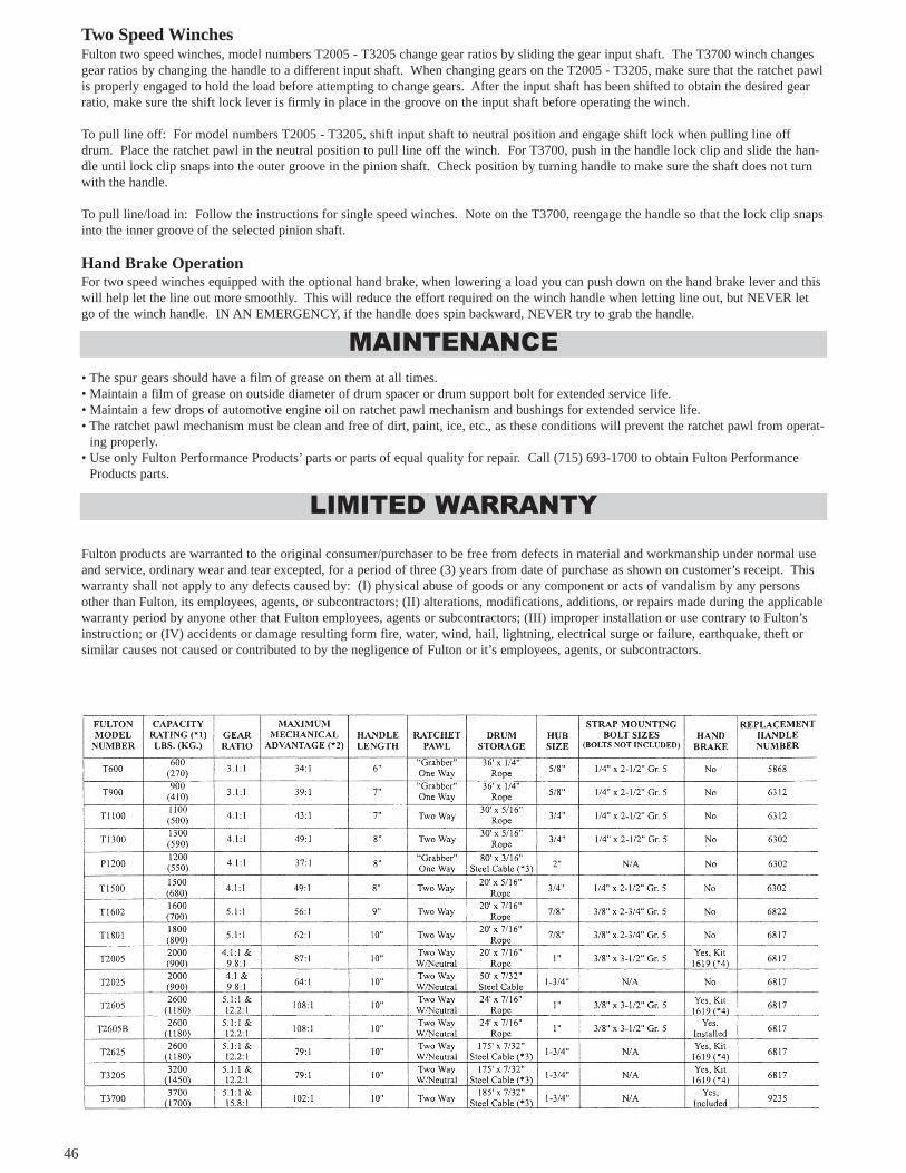
46
Two Speed WinchesFulton two speed winches, model numbers T2005 - T3205 change gear ratios by sliding the gear input shaft. The T3700 winch changesgear ratios by changing the handle to a different input shaft. When changing gears on the T2005 - T3205, make sure that the ratchet pawlis properly engaged to hold the load before attempting to change gears. After the input shaft has been shifted to obtain the desired gearratio, make sure the shift lock lever is firmly in place in the groove on the input shaft before operating the winch.
To pull line off: For model numbers T2005 - T3205, shift input shaft to neutral position and engage shift lock when pulling line offdrum. Place the ratchet pawl in the neutral position to pull line off the winch. For T3700, push in the handle lock clip and slide the han-dle until lock clip snaps into the outer groove in the pinion shaft. Check position by turning handle to make sure the shaft does not turnwith the handle.
To pull line/load in: Follow the instructions for single speed winches. Note on the T3700, reengage the handle so that the lock clip snapsinto the inner groove of the selected pinion shaft.
Hand Brake OperationFor two speed winches equipped with the optional hand brake, when lowering a load you can push down on the hand brake lever and thiswill help let the line out more smoothly. This will reduce the effort required on the winch handle when letting line out, but NEVER letgo of the winch handle. IN AN EMERGENCY, if the handle does spin backward, NEVER try to grab the handle.
• The spur gears should have a film of grease on them at all times.• Maintain a film of grease on outside diameter of drum spacer or drum support bolt for extended service life.• Maintain a few drops of automotive engine oil on ratchet pawl mechanism and bushings for extended service life.• The ratchet pawl mechanism must be clean and free of dirt, paint, ice, etc., as these conditions will prevent the ratchet pawl from operat-
ing properly.• Use only Fulton Performance Products’ parts or parts of equal quality for repair. Call (715) 693-1700 to obtain Fulton Performance
Products parts.
Fulton products are warranted to the original consumer/purchaser to be free from defects in material and workmanship under normal useand service, ordinary wear and tear excepted, for a period of three (3) years from date of purchase as shown on customer’s receipt. Thiswarranty shall not apply to any defects caused by: (I) physical abuse of goods or any component or acts of vandalism by any personsother than Fulton, its employees, agents, or subcontractors; (II) alterations, modifications, additions, or repairs made during the applicablewarranty period by anyone other that Fulton employees, agents or subcontractors; (III) improper installation or use contrary to Fulton’sinstruction; or (IV) accidents or damage resulting form fire, water, wind, hail, lightning, electrical surge or failure, earthquake, theft orsimilar causes not caused or contributed to by the negligence of Fulton or it’s employees, agents, or subcontractors.
MAINTENANCE
LIMITED WARRANTY
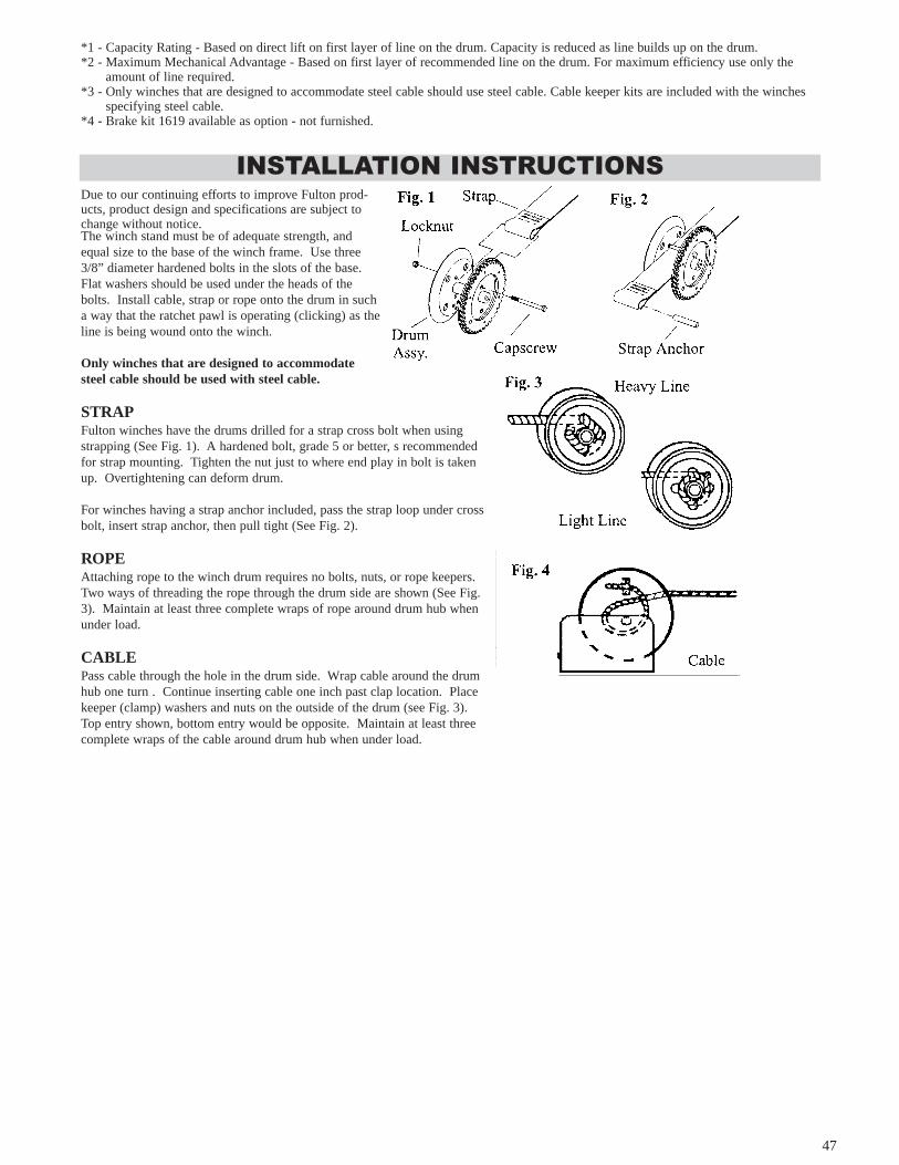
47
*1 - Capacity Rating - Based on direct lift on first layer of line on the drum. Capacity is reduced as line builds up on the drum.*2 - Maximum Mechanical Advantage - Based on first layer of recommended line on the drum. For maximum efficiency use only the
amount of line required.*3 - Only winches that are designed to accommodate steel cable should use steel cable. Cable keeper kits are included with the winches
specifying steel cable.*4 - Brake kit 1619 available as option - not furnished.
Due to our continuing efforts to improve Fulton prod-ucts, product design and specifications are subject tochange without notice.The winch stand must be of adequate strength, andequal size to the base of the winch frame. Use three3/8” diameter hardened bolts in the slots of the base.Flat washers should be used under the heads of thebolts. Install cable, strap or rope onto the drum in sucha way that the ratchet pawl is operating (clicking) as theline is being wound onto the winch.
Only winches that are designed to accommodatesteel cable should be used with steel cable.
STRAPFulton winches have the drums drilled for a strap cross bolt when usingstrapping (See Fig. 1). A hardened bolt, grade 5 or better, s recommendedfor strap mounting. Tighten the nut just to where end play in bolt is takenup. Overtightening can deform drum.
For winches having a strap anchor included, pass the strap loop under crossbolt, insert strap anchor, then pull tight (See Fig. 2).
ROPEAttaching rope to the winch drum requires no bolts, nuts, or rope keepers.Two ways of threading the rope through the drum side are shown (See Fig.3). Maintain at least three complete wraps of rope around drum hub whenunder load.
CABLEPass cable through the hole in the drum side. Wrap cable around the drumhub one turn . Continue inserting cable one inch past clap location. Place keeper (clamp) washers and nuts on the outside of the drum (see Fig. 3). Top entry shown, bottom entry would be opposite. Maintain at least three complete wraps of the cable around drum hub when under load.
INSTALLATION INSTRUCTIONS

48
LIMITED WARRANTY PRE DELIVERY SERVICEDamage to any trailer components may occur during transporting to the dealer. Normally, any defect or damage occurring during
assembly or in loading is detected and corrected at the factory during the inspection process. The dealer will repair any uncorrected facto-ry defects or transit damage before the trailer is delivered to you.
This warranty does not cover alteration of the trailer, or failure caused by such alteration.Karavan Trailers and Distributor/Dealers reserve the right to make trailer modifications or changes at anytime without incurring any
obligation to make the same changes on trailers previously built and/or sold by them.
WARRANTY PRE-AUTHORIZATIONAll warranty returns must be approved by Karavan’s customer service representative. Only original production parts installed by
Karavan Trailers will be accepted for warranty consideration. Any parts returned other than parts used in Karavan production will bereturned to customer at customer’s expense.
YOUR LEGAL RIGHTS UNDER KARAVAN’S LIMITED WARRANTIESAll Karavan limited warranties are the only expressed written warranties made by Karavan applicable to Karavan Trailers. These
limited warranties give you specific legal rights and you may also have other rights which will vary from state to state. Depending on thestate in which your trailer is registered you may have some implied warranties. These implied warranties are limited, to the extent allowedby law, for the time period covered by Karavan Trailers written warranties.
Some states do not allow limitations on how long an implied warranty lasts, so the above limitations may not apply to you.
SUBSEQUENT BUYER/OWNERThe Karavan Trailer warranty is only extended to the first buyer/owner of the trailer. This is defined as the first legal owner of the
Karavan Trailer other than an authorized distributor or dealer who has brought the trailer from Karavan for resale to the public.
WARRANTY INFORMATIONIf you experience any difficulties or defects with parts of the trailer please look for the manufacturers name on the part and contact
them directly. The following is a list of Karavan’s current vendors from whom parts are purchased.
Vendor Phone # Part
Buchanan Industries 888-838-0489 Blue Rollers, Endcaps, Keel Pads
CH Yates 508-674-3378 Rubber Rollers
Fulton/Wesbar 715-693-1700 Lights, Wire Harness, Actuators,
Brakes, Couplers, Winches, Jacks
Tie Down Engineering 800-241-1806 Actuator, Hubs
UFP 800-854-1905 Hubs, Brake Drums, Actuators,
Disc Brakes
SST Bearing 513-583-5500 Bearings & Seals
Atwood Mobile 815-877-7461 Actuators, Brakes
Rockwell American 800-400-3267 Springs
Global Advantage 715-855-7702 Safety Chains
Dexter 260-495-5100 Torsion Axles
Carlisle 800-260-7959 Tires
Kenda 800-225-4714 Tires
Nankang 800-227-8925 Tires
TRAILER WARRANTY

49
KARAVAN TRAILERSP.O. BOX 27FOX LAKE, WISCONSIN 53933
PLACESTAMPHERE
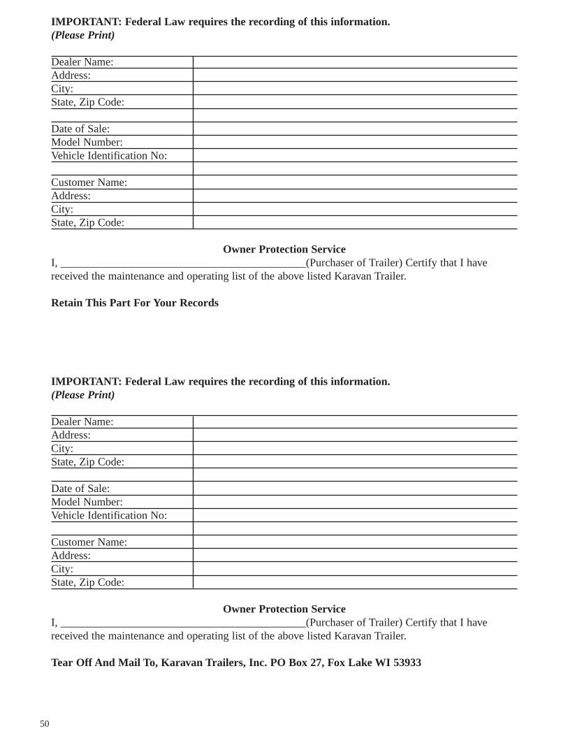
50
IMPORTANT: Federal Law requires the recording of this information.(Please Print)
Dealer Name:Address:City:State, Zip Code:
Date of Sale:Model Number:Vehicle Identification No:
Customer Name:Address:City:State, Zip Code:
Owner Protection ServiceI, ____________________________________________(Purchaser of Trailer) Certify that I havereceived the maintenance and operating list of the above listed Karavan Trailer.
Retain This Part For Your Records
IMPORTANT: Federal Law requires the recording of this information.(Please Print)
Dealer Name:Address:City:State, Zip Code:
Date of Sale:Model Number:Vehicle Identification No:
Customer Name:Address:City:State, Zip Code:
Owner Protection ServiceI, ____________________________________________(Purchaser of Trailer) Certify that I havereceived the maintenance and operating list of the above listed Karavan Trailer.
Tear Off And Mail To, Karavan Trailers, Inc. PO Box 27, Fox Lake WI 53933