Embed Size (px)
Citation preview

'
𝑘
Kapal: Jurnal Ilmu Pengetahuan dan Teknologi Kelautan, 18(1) (2021): 51-57 51
Kapal: Jurnal Ilmu Pengetahuan dan Teknologi Kelautan(Kapal: Journal of Marine Science and Technology)P
journal homepage : http://ejournal.undip.ac.id/index.php/kapal2301-9069 (e)1829-8370 (p)
Experimental Investigation of Bow Slamming on a Ship: The Effect of Weight andImpact Angle
H)Check for
Suandar Basoir), Andi Nadia Himaya2) , Faizal Arya Samman3), Andi Dian Eka Anggriani11, Rosmani11
11Department of Naval Architecture, Faculty of Engineering, Hasanuddin University, Gowa 92171, Indonesia2) Department of Transportation and Environmental System, Hiroshima University, Hiroshima 739-8527, Japan3) Department ofElectrical Engineering, Faculty of Engineering, Hasanuddin University, Gowa 92171, Indonesia
*' Corresponding Author : [email protected]
Article Info Abstract
Keywords:Bow Slamming;Dropping Test;Impact Pressure:Peak Pressure Coefficient
The impact pressure induced by slamming can imply physical damage on a ship. The high probabilityof the slamming impact is on the bow part in the actual sea state. In this present study, the slamminginduced pressure on the bow flare of a ship have been investigated through the experiment. Theexperiment was schemed by the dropping test based on free-falling body in the wave tank, whereinthe bow of the ship model was inclined in several impact angles 0° to 30° to the free-water surface. Tomeasure slamming impact pressure acting on the bow flare, the piezoelectric sensors SI, S2, S3, S4were attached to the bow section and installed on a computer. As the obtained results, the impactpressure on bow flare occurred in a short time duration caused by slamming. The discrepancy of thepeak impact pressure between ship model weight of 2.42 kg and 7.29 kg for the impact angle 0° is70.36% SI, 69.52% S2, 68.97% S3, and 68.34% S4. For the relative impact angle of 30°, the discrepancy is67.02% SI, 65.73% S2, 58.51% S3, and 48.21% S4. The tendency of the peak pressure coefficient at thesequenced impact points SI, S2, S3, S4 is similar for all impact angles 0°, 10°, 20°, and 30°. The peakpressure coefficient due to the full load condition is highest in the nearest bottom part, and the peakpressure coefficients due to the lightship condition highest in the nearest bottom part caused by the
Article history:Received: 11/01/21Last revised: 06/01/21Accepted: 07/02/21Available online: 07/02/21Published: 28/02/21
DOI:https://doi.org/10.14710/kapal. small impact angle.vl8il.35663
Copyright © 2021 Kapal: Jurnal Ilmu Pengetahuan dan Teknologi Kelautan.This is an open access articleunder the CC BY-SA license (https://creativecommons.Org/Iicenses/by-sa/4.0/).
1. Introduction
When a ship sailing in waves is sometimes experiencing slamming events. Slamming is a phenomenon that indicatesnonlinear interaction between ship hull and wave within the water entry process and results short duration of high forceand pressure and dynamic response. The effect of this phenomenon can imply damage, capsizing, or sinking. Therefore, thecharacteristics of ship slamming should be investigated, and then the investigation results are the considerations in obtainingproper ship hull form and construction designs.
Subjected to the study of slamming impact, von Karman [1] and Wagner [2] had firstly conducted, hereinafter theenormous number of studies subjected to the slamming impacts and its effects on a ship has been carried out by usingnumerical and experimental methods. The following, some related studies in the last decade have been presented. Theinvestigations of slamming induced pressure and load in two-dimensional (2D) ship model section have been developed byusing the finite element software ABAQJJS [3], explicit FEM code LS-DYNA [4], finite element code ABAQUS [5], combinedstrip theory, and smoothed particle hydrodynamics (SPH) approach [6], the boundary element method (BEM) code andFLUENT code [7], 2D generalized Wagner model [8], the moving particle semi-implicit (MPS) method involving Prandtl smixing length method and the -epsilon method [9], Although the 2D approach has sufficient results, however, it is still notrelevant in the reality of the slamming problem. Also, this becomes less appropriate if the results are validated using theexperimental results.
The slamming investigations using the three-dimensional section have also been carried out by using some methodssuch as the Wagner approach and the boundary element method (BEM) [10], the coupled model of 3D Rankine panel model,3D FEM, and 2D GWM [8], the 3D time-domain nonlinear hydroelastic method [H], seakeeping code and simplified method[121. momentum impact method and dam-breaking method [13]. Those studies have shown high accurate results by thedeveloped numerical method, and then these results have been validated with the experimental results.

'
Kapal: Jurnal Ilmu Pengetahuan dan Teknologi Kelautan, 18(1) (2021): 51-57
On the other hand, few experimental methods have shown satisfaction by using the elastic body. In these studies, theexperiment devices to accomplish a ship's body entering the water had been introduced. The wedge model was driven byusing an actuator programmed to execute triangular wave trains [14], The Slingshot Impact Testing System (SITS) wasdesigned to study experimentally slamming loads [15], The drop tower and the sliding trolley connected to the parallelfixture was designed [16], The oil pressure actuator system was designed for the injection of heavy steel wedges with thesafety device [17], However, those experiment devices that were used possibly affect a result, and it is a possible differencecompared with the free-fall test.
The water entry of a floating body is interested in being studied regarding the slamming loads acting on a floating body.The dropping test of a ship model with a free-fall approach is the most appropriate way to describe the water entry of afloating body and slamming event. However, this method needs a specialized technique and proper measurement device toobtain accurate results.Therefore, the consideration of the experiment equipment and experimental design is an appropriateway. Nevertheless, an experimental investigation remains to be needed to interpret and enrich physical understanding fromthe resultant nonlinear interaction between ship and wave-induced slamming impact.
In this present study, the impact pressure resulted through dropping test by free fall way of a ship model has beeninvestigated to characterize the effect of the relative impact angle and the model weight on bow slamming. The ship s bowangles to the water-free surface have been considered from 0° to 30°, and four sensor devices have been attached to the bowflare surface of the ship model. By characterizing bow slamming through the experimental investigation, the bow slammingof a ship in waves could be interpreted.
52
2. Methods
The ship slamming is described by an impact resulting from contact between a ship's body and free surface after liftingupward on a wave. By this description, the dropping test of a ship model has been conducted to obtain an impact pressurecaused by slamming. Also, the influence of the weight and bow impact angle of the ship were investigated in this experiment.The weights of the ship model were considered 2.42 kg and 7.29 kg, and they were respectively defined as the lightship andfull loading conditions.
The experiment was performed at wave tank, Ship Hydrodynamics Laboratory, Naval Architecture Department,Hasanuddin University, Indonesia. The size of the wave tank length is 20 m, the width is 1.5 m, and the depth is 1.3 m. Theship type that was used in the experiment is a container. The lines plan of the ship is shown in Figure 1. The ship model scaleis 1:75, and it was made of fiberglass, as shown in Figure 1. The scale of the ship model considered the size of the wave tank.The main dimensions of the actual ship and model are provided in Table 1. In the bow part, the pressure sensors wereattached to capture the slamming induced pressure. The experimental details are discussed accordingly of the ship model,experiment scheme, experiment equipment, and device.
Table 1. the Main Particulars of the Actual Ship and ModelActual (m) Model (m)Dimension
Length overall, LoALength waterline, LwLLength between perpendiculars, LbPBreadth, BDepth, HDraft, T_
74.4972.4067.7011.50
0.9930.9650.9290.1530.0960.080
7.206.00
jmrz'ÿ
i:K
’ i i i * i j i “
-
___MmmmmmmmBk
*1-—T—*| " '7, -v w! Mi Cli .)-*f-« - 4§ci
/\ KFigure 1. the Ship Lines Plan and Ship Model

Kapal: Jurnal Ilmu Pengetahuan dan Teknologi Kelautan, 18(1) (2021): 51-57 53
m7S~
1,5 m 1,5 m
Figure 2. the Experimental Scheme of The Dropping Test
V:!GNDAOTTLVCC
(a) (b)
%
Wk PC
£5mm(c) (d)
Figure 3. the Installation of the Pressure Sensor Device; (a) Piezoelectric Knock Sensor, (b) Arduino Mega, (c) Breadboard,(d) Block Diagram
's"«
/ “
• \
<E
Figure 4. the Illustration of Piezoelectric Knock Sensors Attached Vertically in Bow Flare of The Model
The experimental method is the dropping test with free fall way. For dropping a ship model, the dropping tower asexperiment equipment was constructed above the wave tank construction. The ship model was hung using a rope in thedropping tower. The distance between the ship model in the dropping tower and the water-free surface in the wave tankwas considered 1.5 m for reaching a relative impact angle on the bow part after dropping a ship model. The bow angle of theship model was fixed from 0° to 30° to the water-free surface.
In the dropping tower, the bow angle of the ship model is adjusted and kept by using two ropes that are tied on the rearand middle part of the ship model connected to the dropping tower. Then, the bow angle is maintained until reaching thewater-free surface. Also, two ropes are needed for tying the starboard and portside of the ship model connected to thedropping tower to avoid a heeling condition of the ship model, and they are freely released during the dropping process. Theship model with the proper condition regarding the expected bow angel is dropped to the water-free surface by cuttingsimultaneously two ropes on the dropping tower. The experiment scheme, dropping test by free fall entry, is illustrated inFigure 2. The time during the dropping process, from the beginning of the dropping the ship model until hitting the water-free surface, is recorded using a camera.
ts = 0 sec ts = 0.42 sec ts = 0.45 sec ts = 0.50 sec
ts = 0 sec ts = 0.40 sec ts = 0.44 sec ts = 0.50 sec
Kapal: Jurnal Ilmu Pengetahuan dan Teknologi Kelautan, 18(1) (2021): 51-57
The sensor device that was used is a piezoelectric knock sensor installed with the Arduino Mega. It is used for measuringimpact pressure due to slamming. The piezoelectric knock sensors are connected to the breadboard and Arduino mega, andthen they are installed on a computer. The block diagram of the device installation is shown in Figure 3. There are fourpressure sensors SI, S2, S3, S4, that ware attached vertically to the bow part of the ship model, as shown in Figure 4. Theposition of the sensor has a distance vertically on the bow flare. By the vertical position of the impact point, the influence ofthe impact point on the bow flare vertically toward pressure distribution due to slamming can be obtained.
The output of the piezoelectric knock sensor is a digital number in a voltage unit (volt). Then, it is calibrated by using aforce measurement device. By pressing the piezoelectric knock sensor, force N working on the sensor is shown in themeasurement device. Then, the impact pressure (Pa) is defined by multiplying the digital number with force per digitalnumber which is divided by the section area of the piezoelectric knock sensor.
54
3. Results and Discussion
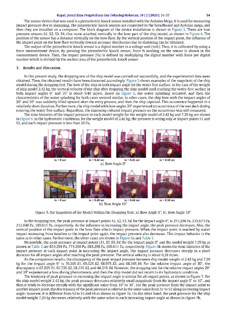
In this present study, the dropping test of the ship model was carried out successfully, and the experimental data wereobtained. Then, the obtained results have been discussed accordingly. Figure 5 shows examples of the snapshots of the shipmodel during the dropping test. The bow of the ship in both impact angle hit the water free surface. In the case of the weightof ship model 2.42 kg, the vertical velocity of the ship after dropping the ship model until reaching the water-free surface inboth impact angles 0° and 10° is about 0.40 m/sec. Based on Figure 5, the water splashing occurred, and then thecharacteristics of the water splashing for both cases seemed similar. In other cases, the ship bow with the impact angles of20° and 30° was suddenly lifted upward after the entry process, and then the ship capsized. This occurrence happened in arelatively short duration. Furthermore, the ship model with bow angles 30° experienced an occurrence of the wet deck duringentering the water free surface. Regardless, the slamming induced impact pressure on the occurrence was still measured.
The time histories of the impact pressure in each model weight for the weight model of 2.42 kg and 7.29 kg are shownin Figure 6. In the hydrostatic conditions, for the weight model of 2.42 kg, the pressure is acting only at impact points SI andS2, and each impact pressure is less than 20 Pa.
f A 11 T”35
0'4
a). Bow Angle 0°
AEBFi
b). Bow Angle 10°
Figure 5. the Snapshots of the Model Within the Dropping Test; a). Bow Angle 0°, b). Bow Angle 10°
In the dropping test, the peak pressure at impact points SJ, S2, S3, S4, for the impact angle 0°, is 253.298 Pa, 235.673 Pa,212.048 Pa, 189.611 Pa, respectively. As the influence in increasing the impact angle, the peak pressure decreases. Also, thevertical position of the impact point in the bow flare affects impact pressure. When the impact point is reached by waterimpact increasing from baseline to the impact point again, the impact pressure also decreases. This impact behavior is thesame as in other cases. Furthermore, the other cases are shown in Figure 6a and Table 2.
Meanwhile, the peak pressure at impact points (SI, S2, S3, S4) for the impact angle 0° and the model weight 7.29 kg asshown in Table 2 are 853.298 Pa, 773.298 Pa, 683.298 Pa, 599.611 Pa, respectively. Figure 6b shows the time histories of theimpact pressure at each impact point in increasing the impact angle. The impact pressure decreases steeply in a shortduration for all impact angles after reaching the peak pressure. The vertical velocity is about 0.28 m/sec.
As the comparison results, the discrepancy of the peak impact pressure between ship model weight of 2.42 kg and 7.29kg for the impact angle 0° is 70.36% S/, 69.52%S2, 68.97% S3, and 68.34%S4. For the relative impact angle of 30°, thediscrepancy is 67.02% SI, 65.73% S2, 58.51% S3, and 48.21% S4. Plowever, the dropping test for the relative impact angles 20°and 30° experienced a bow diving phenomenon, and then the ship model did not return to its hydrostatic condition.
The tendency of peak pressure in increasing the impact angle is similar for all impact points, as shown in Figure 7. Forthe ship model weight 2.42 kg, the peak pressure decreases relatively small magnitude from the impact angle 0° to 10°, andthen it tends to decrease steeply with the significant value from 10° to 30°. For the peak pressure from the impact point toanother impact point, the discrepancy of the peak pressure is relative in the same value from SI to S2 along increasing impactangle; however, it is different from S2 to S3 and S4 as shown in Figure 7a. On the other hand, the peak pressure for the shipmodel weight 7.29 kg decreases relatively with the same value in each increasing impact angle as shown in Figure 7b.

ρ ρ
-10
40
90
140
190
240
290
0.420 0.440 0.460 0.480 0.500 0.520 0.540 0.560
Pre
ssu
re (
Pa)
Sensor 1
Sensor 2
Sensor 3
Sensor 4
-50
150
350
550
750
950
0.270 0.295 0.320 0.345 0.370 0.395 0.420
Sensor 1Sensor 2Sensor 3Sensor 4
-10
40
90
140
190
240
290
0.420 0.470 0.520
Pre
ssu
re (
Pa)
-50
150
350
550
750
950
0.270 0.295 0.320 0.345 0.370 0.395 0.420
-10
40
90
140
190
240
0.420 0.470 0.520
Pre
ssu
re (
Pa)
-50
50
150
250
350
450
550
650
0.270 0.295 0.320 0.345 0.370 0.395 0.420
-10
10
30
50
70
90
110
130
150
170
0.420 0.470 0.520
Pre
ssu
re (
Pa)
Time (sec)
-50
50
150
250
350
450
550
0.270 0.295 0.320 0.345 0.370 0.395 0.420Time (sec)
Kapal: Jurnal Ilmu Pengetahuan dan Teknologi Kelautan, 18(1) (2021): 51-57 55
0° 0°
10° 10°
20° 20°
30° 30°(a) (b)
Figure 6. the Time Histories of the Impact Pressure for Model Weight at Sensor Point and Relative Impact Angles;(a). Model Weight 2.42 Kg, (b). Model Weight 7.29 Kg
Table 2. the Peak Pressure at Impact PointModelweight (kg) angle (°)
Relative impact Peak pressure (Pa)SI S2 S3 S4
2.42 0 253.298 235.673 212.048 189.611240.673 218.611 199.245 179.312187.925 165.676 154.239 144.167160.051 137.802 129.177 121.928853.298 773.298 683.298 599.611760.333 669.611 580.245 499.303585.877 502.412 401.111 297.881485.288 411.143 311.312 235.411
102030
7.29 0102030
The impact pressure in association with the impact velocity and impact point position on the bow flare, the impactpressure can be characterized by using the coefficient of the peak pressure. The peak pressure coefficient Cp is defined by
Pmax/0.5 Vi2, where Pmax is the peak pressure, is the water density, and Vi is the impact velocity reaching the impactpoint after hitting the free-water surface. The vertical velocity of the ship model to the free-water surface generates theimpact velocity reaching the impact point within bow entry. The impact velocity is obtained in a short time. The impact

110
130
150
170
190
210
230
250
270
0 10 20 30
Pea
k p
ress
ure
(P
a)
Relative impact angle (°)
Sensor 1
Sensor 2
Sensor 3
Sensor 4
110
210
310
410
510
610
710
810
910
0 10 20 30
Pea
k p
ress
ure
(P
a)
Relative impact angle (°)
Sensor 1
Sensor 2
Sensor 3
Sensor 4
0
0.2
0.4
0.6
0.8
1
1.2
0.000 0.001 0.002 0.003 0.004 0.005 0.006 0.007 0.008
Cp
(Pm
ax/
0.5ρVi2
)
Vertical distance impact point (m)
0 degree
10 degrees
20 degrees
30 degrees
0
0.2
0.4
0.6
0.8
1
1.2
1.4
1.6
1.8
0.000 0.001 0.002 0.003 0.004 0.005 0.006 0.007 0.008
Cp
(Pm
ax/
0.5ρVi2
)
Vertical distance impact point (m)
0 degree
10 degrees
20 degrees
30 degrees
Kapal: Jurnal Ilmu Pengetahuan dan Teknologi Kelautan, 18(1) (2021): 51-57
velocity for the model weight 2.42 kg in reaching the impact points SI, S2, S3, S4 are obtained 0.007 cm/sec, 0.020 m/sec,0.033 cm/sec, and 0.047 m/sec, respectively. For the ship model weight 7.29 kg, the impact velocity at SI, S2, S3, S4 is 0.01m/sec, 10.015 m/sec, 0.017 m/sec and 0.018 m/sec, respectively. Figure 8 shows the peak pressure coefficient at impact pointsfor each impact angle. The tendency of the peak pressure coefficient at the sequenced impact points SI, S2, S3, S4 is similarfor all impact angles 0°, 10°, 20°, and 30°. The peak pressure coefficient tends to decrease acting on bow flare in increasingthe bow immersed (vertical impact point). However, the peak pressure coefficient decreases steeply and gradually in a smalldiscrepancy from the body immersed 0.01 m to 0.03 m. In the comparison result of the peak pressure coefficients, the peakpressure coefficient for the impact angle 0° and ship model weight 7.29 kg is highest in increasing bow immersed.
56
(a) Model weight 2.42 kg (b) Model weight 7.29 kg
Figure 7. the Tendency of Peak Pressure due to Model Weight in Increasing the Relative Impact Angle
The overall result of the peak pressure coefficient for the model weight 7.29 kg, as shown in Figure 8b is higher thanthe ship model weight of 2.42 kg, as shown in Figure 8a. Based on Figure 8, the peak pressure coefficients due to the shipmodel weight of 7.29 kg in the impact point SI (nearest bottom part) are higher than 1.0 for all impact angles, and there aretwo peak pressure coefficients due to the weight of 2.42 kg in the impact point SI (nearest bottom part) are higher than 1.00given by the impact angle 0° and 10°. The peak pressure coefficient higher than 1.0 indicates that a ship suffers high impactpressure, and this condition can be a ship that leads possible to damage.
(a); (b)
Figure 8. the Peak Pressure Coefficient in Vertical Distance Impact Point Influenced by the Model Weight;(a) 2.42 Kg, (b) 7.29 Kg
Based on the discussion above, this present result emphasizes a notable finding that a ship in slamming conditionsexperiences the dynamic responses of the high impact pressure in the bottom and bow part with a small impact angle. Theship with full loading condition and a small impact angle in the slamming event is also induced by the high peak impactpressure and leads to the most vulnerable damage. Therefore, the ship with full load conditions in slamming conditions hasto be an attention to the ship navigation. In addition, the ship experiences water on deck, and the bow diving phenomenonpossible occurs when the impact angle becomes larger. Regardless, the bottom and bow parts of a ship should be designedproperly to reduce impact pressure due to slamming conditions.
4. Conclusion
The influence of the impact angle in the slamming event, the peak pressure decreases in increasing the impact angle.Also, the vertical position of the impact point in the bow flare affects impact pressure induced by slamming. The impactpressure decreases steeply in a short duration after reaching the peak pressure. The tendency of peak pressure in increasingthe impact angle is similar to acting on the bow flare.
Regarding the effect of ship weight, the peak pressure decreases relatively small value due to the small impact angle. Ittends to decrease steeply with the significant value by the high impact angle. The discrepancy of the peak pressure is relativein the same value acting on the nearest bottom part along increasing impact angle, and it is different on the high bow part.

'
" "
“ ”
"
"
"
" –
"
"
" "
"
"
"
"
"
" –
"
"
" "
"
"
"
"
" "
"
"
"
"
Kapal: Jurnal Ilmu Pengetahuan dan Teknologi Kelautan, 18(1) (2021): 51-57
In increasing the ship s weight, the peak pressure decreases relatively with the same value in each increasing impact angleof the bow flare to free-water surface.
The tendency of the peak pressure coefficient in the immersed bow flare is similar for any impact angle of the bow flare.The peak pressure coefficient tends to decrease acting on bow flare in increasing the immersed bow flare. However, the peakpressure coefficient decreases steeply and gradually in a small discrepancy from the immersed bow flare in the nearestbottom part.
The peak pressure coefficient due to the full load condition is highest in the nearest bottom part. However, the peakpressure coefficients due to the lightship condition highest in the nearest bottom part caused by the small impact angle. Thehighest peak pressure coefficient in the nearest bottom part indicates the ship bow suffers high impact pressure, and thiscondition can be a ship bow that leads possible to damage.
This present result emphasizes a notable finding that a ship in slamming conditions experiences the dynamic responsesof the high impact pressure in the bottom and bow part with a small impact angle. Moreover, the ship experiences water ondeck, and the bow diving phenomenon possible occurs when the impact angle becomes larger. Regardless, the bottom andbow parts of a ship should be designed properly to reduce impact pressure due to slamming conditions.
57
References
[1] T. von Karman, The Impact on Seaplane Floats During Landing, Technical note, National Advisory Committee forAeronautics, No. 321, pp. 309-313, 1929.
[2] H. Wagner, Uber Stossund Gleitvergange an der Oberflache von Flussigkeiten, Zeitschrift fuer AngewandteMathematik und Mechanik, vol. 12, pp. 193-215, 1932.
[3] A. Tassin, N. Jacques, A. Alaoui, A. Neme and B. Leble, Assessment and Comparison of Several Analytical Models ofWater Impact, InternationalJournal of Multiphysics, vol. 4, No. 2, pp. 125-140, 2010. doi: 10.1260/1750-9548.4.2.125
[4] H. Luo, S. Wang and C. G. Soares, Numerical Prediction of Slamming Loads on a Rigid Wedge Subjected to Water EntryUsing an Explicit Finite Element Method. Advances in Marine Structures, Guedes Soares & Fricke (eds), pp. 41-48,2011.
[5] A. Constantinescu, A. Alaoui, A. Neme, N. Jacques and P. Rigo, Numerical and Experimental Studies of SimpleGeometries in Slamming, InternationalJournal of Offshore and Polar Engineering, vol. 21, no. 3, pp. 216 224, 2011.
[6] D.J. Veen and T. P. Gourlay, A Combined Strip Theory and Smoothed Particle Hydrodynamics Approach for EstimatingSlamming Loads on a Ship in Head Seas, Ocean Engineering, vol. 43, pp. 64-71, 2012. doi:10.1016/j.oceaneng.2012.01.026
[7] S. H. Kwon, Y. J. Yang and H. S. Lee, Experimental and Numerical Study on Slamming Impact, Journal of OceanEngineering and Technology, vol. 27, no.1, pp. 1-8, 2013. doi: 10.5574/KSOE.2013.27.1.001
[8] J. H. Kim and Y. Kim, Parametric Study of Numerical Prediction of Slamming and Whipping and an ExperimentalValidation for a 10,000-TEU Containership, Journal ofAdvanced Research in Ocean Engineering, vol. 1, no.2, pp. 115-133, 2015. doi: 10.5574/JAROE.2015.1.2.115
[9] F. Han, J. Yao, C. Wang and H. Zhu, Bow Flare Water Entry Impact Prediction and Simulation Based on Moving ParticleSemi-Implicit Turbulence Method, Shock and Vibration, vol. 2018, pp. 1-16. 2018. doi: 10.1155/2018/7890892
[10] A. Tassin, N. Jacques, A. Neme and B. Leble, An Efficient Numerical Method for the Three-Dimensional WagnerProblem, Proceeding of the 25th International Workshop on Water Waves and Floating Bodies IWWWFB, Harbin,China, 2010.
[11] J. Jiao, H. Ren and C. A. Adenya, Experimental and Numerical Analysis of Hull Girder Vibrations and Bow Impact of aLarge Ship Sailing in Waves, Shock and Vibration, vol. 2015, pp. 1-10, 2015. doi: 10.1155/2015/706163
[12] S. Wang, S. Rajendran and C. G. Soares, Investigation of Bottom Slamming on Ships in Irregular Waves, Proceedingof the 37th International Conference on Ocean, Offshoreand Arctic Engineering OMAE, Madrid, Spain, 2018.
[13] J. Jiao, Y. Zhao, Y. Ai, C. Chen and T. Fan, Theoretical and Experimental Study on Nonlinear Hydroelastic Responsesand Slamming Loads of Ship Advancing in Regular Waves, Shock and Vibration, vol. 2018, pp. 1-26, 2018. doi:
10.1155/2018/2613832[14] T. Truong, N. Repalle, F. Pistani and K. Thiagarajan, An Experimental Study of Slamming Impact During Forced Water
Entry, Proceeding of the 17th Australian Fluid Mechanics Conference, Auckland, New Zealand, pp. 1-4, 2010.[15] F. J. H. Huarte and D. J. M. G. Gharib, Experimental Investigation of Water Slamming Loads on Panels, Ocean
Engineering, vol. 38, Issue 11-12, pp. 1347-1355, 2011. doi: 10.1016/j.oceaneng.2011.06.004[16] M. Nikfarjam, O. B. Yaakob, M. S. Seif andj. Koto, Investigation of Wedge Water-Entry Linder Symmetric Impact Loads
by Experimental Tests, Latin American Journal of Solids and Structures, 14, pp. 861-873, 2017. doi: 10.1590/1679-78253315
[17] H. Shin, B. Seo and S. R. Cho, Experimental Investigation of Slamming Impact Acted on Flat Bottom Bodies andCumulative Damage, InternationalJournal of Naval Architecture and Ocean Engineering, vol. 10, no. 3, pp. 294-306,2018. doi: 10.1016/j.ijnaoe.2017.06.004