Embed Size (px)
Citation preview
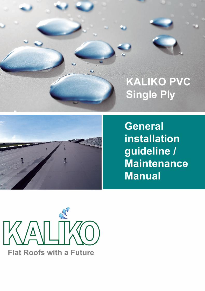
General installation guideline / Maintenance Manual
KALIKO PVC Single Ply
Flat Roofs with a Future
The enclosed technical details and recommendations contained are a guide based on our knowledge and experience. Installer must be sure that material is suitable for the correct waterproofing application, being responsible for the installation of the products and for any consequential loss deriving from the installation of the system.
For any further information please contact our technical department.
Introduction Compatibility Membrane cleaning procedure Equipment Welding overlap Hand welding procedure Main weld Automatic welding Welding T-Joints Mechanical fixing to a horizontal surface Mechanical fixing to a vertical surface Perimeter fixing Adhered to a horizontal surface Adhered to a vertical surface Accessories Internal corner detail Internal corner with a vertical crease External corner detail Vent/pipe detail Outlet detail Perimeter edge flashing Parapet wall detail Internal perimeter edge flashing External corner to perimeter edge flashing Wall termination profile Seam testing procedure Damage repairs Welding to an existing PVC membrane
3
4
5
6
6
7
8
8
9
10
11
12
13
1314
14
1516171819
20202122222323
Index
2
Flat Roofs with a Future
This manual is a general guideline about Kaliko membranes for authorised installers.
Membranes and application f
Kaliko SF15 a polyester-reinforced membrane produced in a single multi-extrusion process. The membrane is suitable for mechanically-fixed, exposedroof applications. It is also used for detail flashings.
Kaliko FB15 a polyester reinforced membrane produced in a coatingprocess. The membrane has a 300 g/m2 non-woven fleece backing. Material suitable for mechanically-fixed, adhered, exposed roof applications over incompatible or rough surfaces.
Kaliko GL15 a glass-mat-reinforced membrane produced in a single multi-extrusion process. The membrane is suitable for loose-laid, ballasted, roof gardens, utility and parking decks. It is also used for bonding to exposed roof areas and detail flashings.
Kaliko FB GL15 a glass-mat-reinforced membrane produced in a coating process. The membrane has a 300 g/m2 polyester fleece backing. Material suitable for bonded exposed roof applications.
Kaliko F15 an unreinforced membrane suitable on areas where detail work cannot be achieved with Kaliko accessories, e.g. corners, pipes, vents. This membrane is not intended, or suitable, for large horizontal or vertical roof applications.
1. Storage
Kaliko PVC membranes are delivered in rolls and on pallets to site. Material must be stored in a dry place, elevated from the ground/roof and protected against exposure to rain, frost and snow.
2. Labelling
Kaliko rolls are individually labelled with batch code, length, thickness and width.
Introduction
3
4
Compatibility
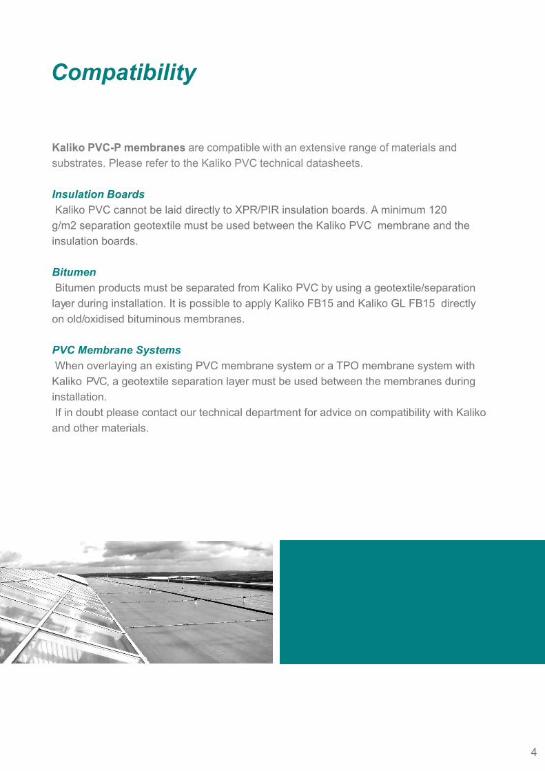
Kaliko PVC-P membranes are compatible with an extensive range of materials and substrates. Please refer to the Kaliko PVC technical datasheets.
Insulation Boards Kaliko PVC cannot be laid directly to XPR/PIR insulation boards. A minimum 120g/m2 separation geotextile must be used between the Kaliko PVC membrane and the insulation boards.
Bitumen Bitumen products must be separated from Kaliko PVC by using a geotextile/separation layer during installation. It is possible to apply Kaliko FB15 and Kaliko GL FB15 directly on old/oxidised bituminous membranes.
PVC Membrane Systems When overlaying an existing PVC membrane system or a TPO membrane system with Kaliko PVC, a geotextile separation layer must be used between the membranes during installation. If in doubt please contact our technical department for advice on compatibility with Kaliko and other materials.
4
Membrane cleaning procedure
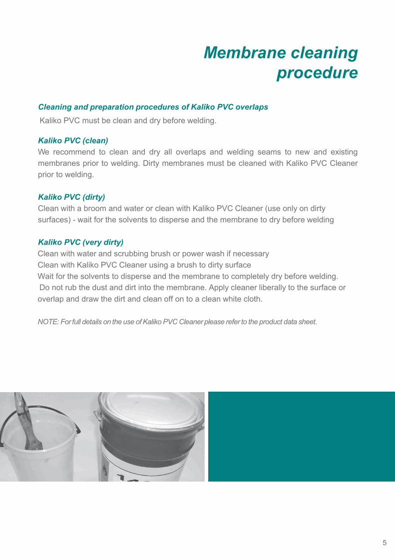
Cleaning and preparation procedures of Kaliko PVC overlaps Kaliko PVC must be clean and dry before welding.
Kaliko PVC (clean)We recommend to clean and dry all overlaps and welding seams to new and existing membranes prior to welding. Dirty membranes must be cleaned with Kaliko PVC Cleaner prior to welding.
Kaliko PVC (dirty)Clean with a broom and water or clean with Kaliko PVC Cleaner (use only on dirty surfaces) - wait for the solvents to disperse and the membrane to dry before welding
Kaliko PVC (very dirty)Clean with water and scrubbing brush or power wash if necessaryClean with Kaliko PVC Cleaner using a brush to dirty surfaceWait for the solvents to disperse and the membrane to completely dry before welding. Do not rub the dust and dirt into the membrane. Apply cleaner liberally to the surface or overlap and draw the dirt and clean off on to a clean white cloth.
NOTE: For full details on the use of Kaliko PVC Cleaner please refer to the product data sheet.
5
Overlap width
Equipment
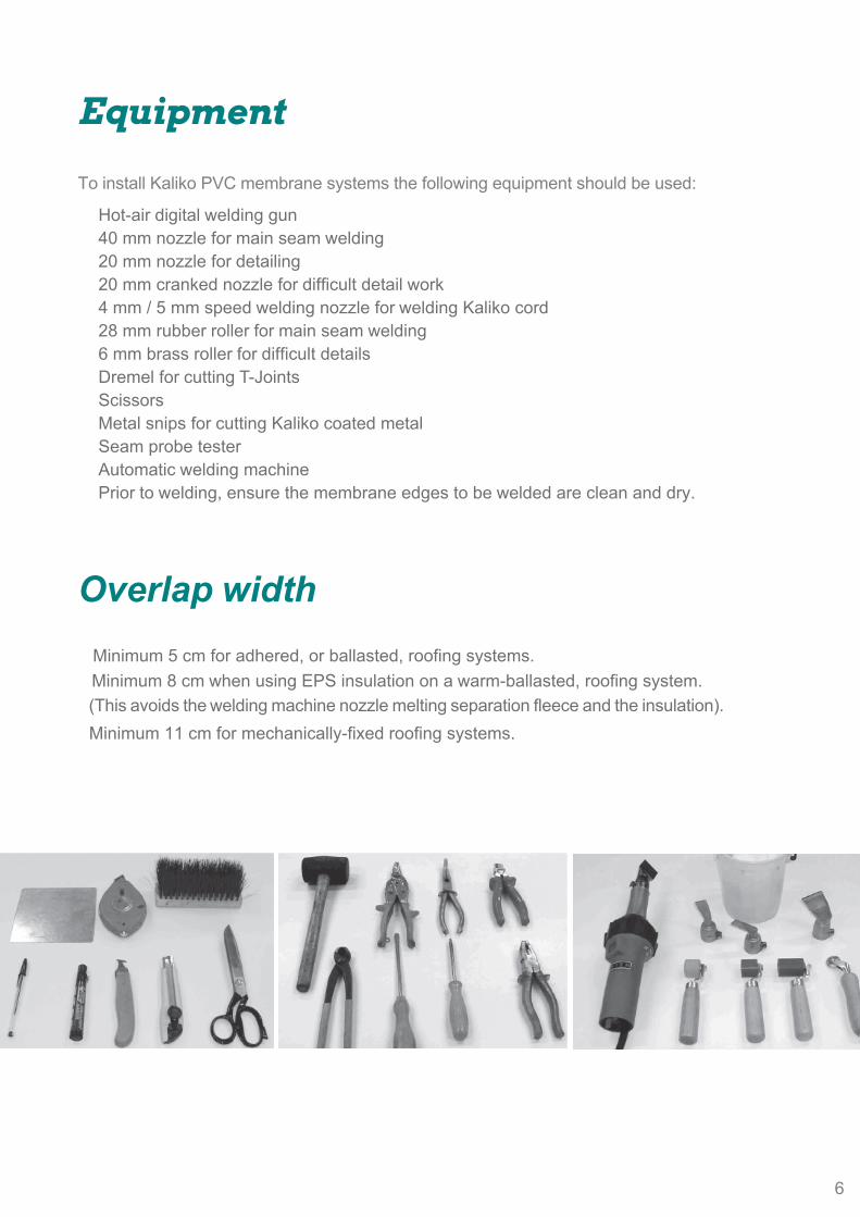
To install Kaliko PVC membrane systems the following equipment should be used:
Hot-air digital welding gun40 mm nozzle for main seam welding20 mm nozzle for detailing20 mm cranked nozzle for difficult detail work4 mm / 5 mm speed welding nozzle for welding Kaliko cord28 mm rubber roller for main seam welding6 mm brass roller for difficult detailsDremel for cutting T-JointsScissorsMetal snips for cutting Kaliko coated metalSeam probe testerAutomatic welding machinePrior to welding, ensure the membrane edges to be welded are clean and dry.
Minimum 5 cm for adhered, or ballasted, roofing systems.Minimum 8 cm when using EPS insulation on a warm-ballasted, roofing system.
(This avoids the welding machine nozzle melting separation fleece and the insulation). Minimum 11 cm for mechanically-fixed roofing systems.
6
Hand welding procedure
Nozzle care
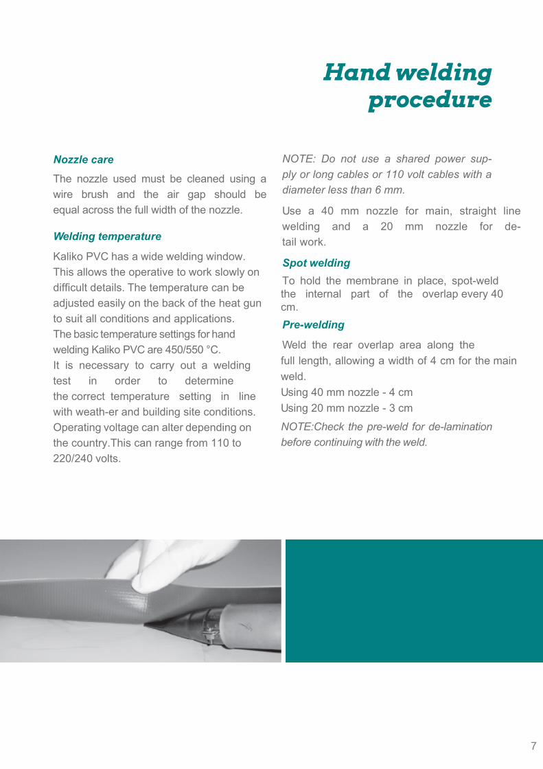
The nozzle used must be cleaned using a wire brush and the air gap should be equal across the full width of the nozzle.
Welding temperature
Kaliko PVC has a wide welding window. This allows the operative to work slowly on difficult details. The temperature can be adjusted easily on the back of the heat gun to suit all conditions and applications.The basic temperature settings for hand welding Kaliko PVC are 450/550 °C.It is necessary to carry out a welding test in order to determine the correct temperature setting in line with weath-er and building site conditions.Operating voltage can alter depending on the country.This can range from 110 to 220/240 volts.
NOTE: Do not use a shared power sup-ply or long cables or 110 volt cables with a diameter less than 6 mm.
Use a 40 mm nozzle for main, straight line welding and a 20 mm nozzle for de-tail work.
Spot weldingTo hold the membrane in place, spot-weld the internal part of the overlap every 40 cm.Pre-welding
Weld the rear overlap area along the full length, allowing a width of 4 cm for the main weld.Using 40 mm nozzle - 4 cm Using 20 mm nozzle - 3 cmNOTE:Check the pre-weld for de-lamination before continuing with the weld.
7
8
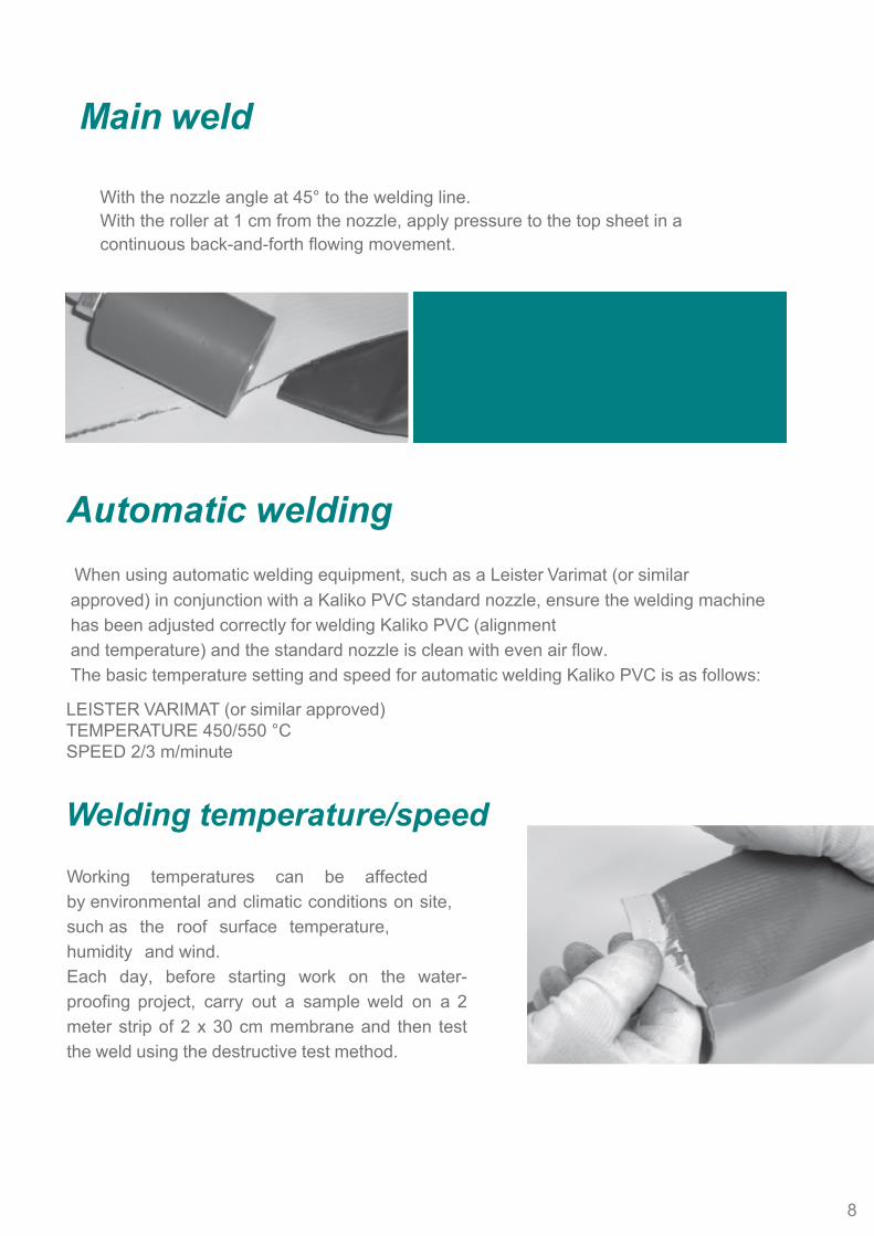
Main weld
With the nozzle angle at 45° to the welding line.With the roller at 1 cm from the nozzle, apply pressure to the top sheet in a continuous back-and-forth flowing movement.
Automatic welding When using automatic welding equipment, such as a Leister Varimat (or similar approved) in conjunction with a Kaliko PVC standard nozzle, ensure the welding machine has been adjusted correctly for welding Kaliko PVC (alignmentand temperature) and the standard nozzle is clean with even air flow.The basic temperature setting and speed for automatic welding Kaliko PVC is as follows:
LEISTER VARIMAT (or similar approved)TEMPERATURE 450/550 °CSPEED 2/3 m/minute
Welding temperature/speed
Working temperatures can be affected by environmental and climatic conditions on site, such as the roof surface temperature, humidity and wind.Each day, before starting work on the water-proofing project, carry out a sample weld on a 2 meter strip of 2 x 30 cm membrane and then test the weld using the destructive test method.
8
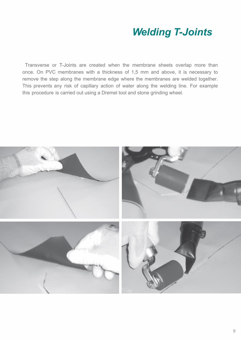
Welding T-Joints
Transverse or T-Joints are created when the membrane sheets overlap more than once. On PVC membranes with a thickness of 1,5 mm and above, it is necessary to remove the step along the membrane edge where the membranes are welded together. This prevents any risk of capillary action of water along the welding line. For example this procedure is carried out using a Dremel tool and stone grinding wheel.
9
10
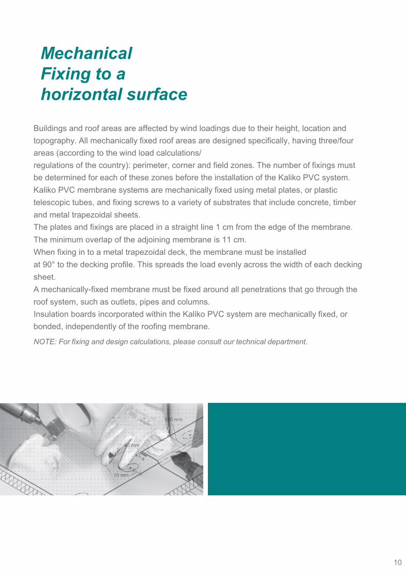
Mechanical Fixing to a horizontal surface
Buildings and roof areas are affected by wind loadings due to their height, location and topography. All mechanically fixed roof areas are designed specifically, having three/four areas (according to the wind load calculations/regulations of the country): perimeter, corner and field zones. The number of fixings must be determined for each of these zones before the installation of the Kaliko PVC system.Kaliko PVC membrane systems are mechanically fixed using metal plates, or plastic telescopic tubes, and fixing screws to a variety of substrates that include concrete, timber and metal trapezoidal sheets.The plates and fixings are placed in a straight line 1 cm from the edge of the membrane. The minimum overlap of the adjoining membrane is 11 cm.When fixing in to a metal trapezoidal deck, the membrane must be installedat 90° to the decking profile. This spreads the load evenly across the width of each decking sheet.A mechanically-fixed membrane must be fixed around all penetrations that go through the roof system, such as outlets, pipes and columns.Insulation boards incorporated within the Kaliko PVC system are mechanically fixed, or bonded, independently of the roofing membrane.
NOTE: For fixing and design calculations, please consult our technical department.
10
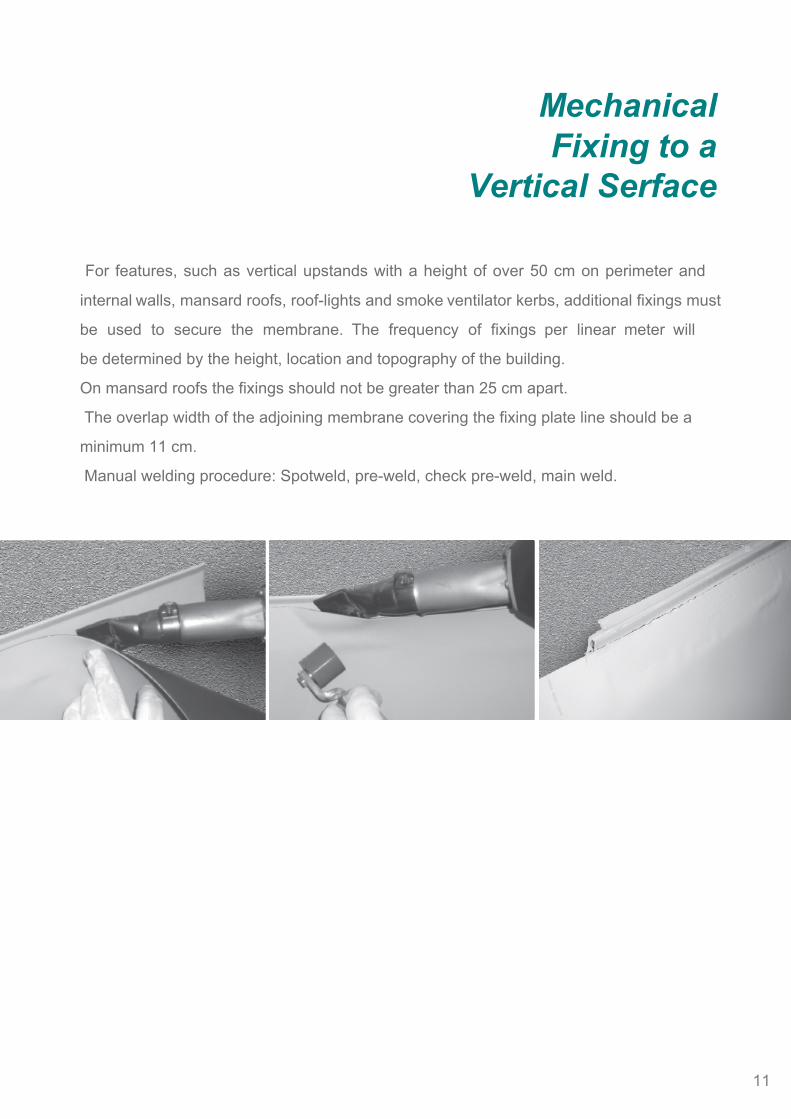
For features, such as vertical upstands with a height of over 50 cm on perimeter and
internal walls, mansard roofs, roof-lights and smoke ventilator kerbs, additional fixings must
be used to secure the membrane. The frequency of fixings per linear meter will
be determined by the height, location and topography of the building.
On mansard roofs the fixings should not be greater than 25 cm apart.
The overlap width of the adjoining membrane covering the fixing plate line should be a
minimum 11 cm.
Manual welding procedure: Spotweld, pre-weld, check pre-weld, main weld.
Mechanical Fixing to a
Vertical Serface
11

Perimeter fixing
Kaliko SF15/ FB15Polyester-reinforced membrane systems must be mechanically fastened at all upstands with pre-punched bars, or fixing plates, and screws. The membrane should be secured at the base of the upstand to the horizontal or vertical face.
Kaliko FB GL15Glass-mat-reinforced membranes, for use on bonded applications, must be secured at all perim-eters and protrusions through the roof with peel stop bars/plates and fixings. The membrane can be secured at the base of the upstand to the horizontal or vertical face.
Kaliko GL15Glass-mat-reinforced membranes, for use on bal-lasted applications, must be secured at all perimeters and protrusions through the roof with Kaliko pre-punched bars.The membrane can be secured at the base of the upstand to the horizontal or vertical face.The use of Kaliko PVC cord is recommended in conjunction with Kaliko pre-punched bars.The Kaliko pre-punched bars, screws and plates are recommended for perimeters and for all large penetrations through the roof such as roof lights, smoke vents, etc.Ensure a 1 cm gap is left between the Kaliko bars to allow for expansion.To protect the waterproofing membrane from damage during stress loading the bar ends should be covered with a strap of membrane as shown.NOTE: Mechanically fix with plates and screws around smaller penetrations such as pipes, columns and outlets.
12
Adhered to a Horizontal Surface
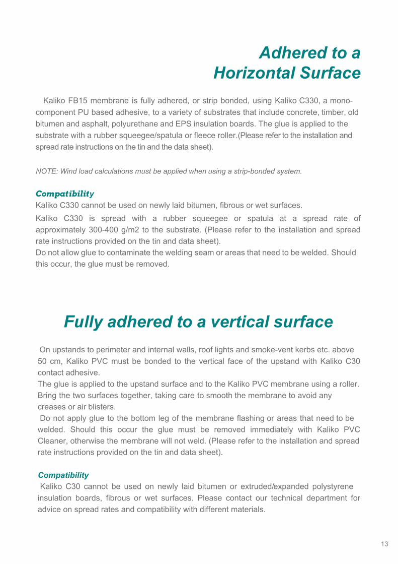
Kaliko FB15 membrane is fully adhered, or strip bonded, using Kaliko C330, a mono-component PU based adhesive, to a variety of substrates that include concrete, timber, old bitumen and asphalt, polyurethane and EPS insulation boards. The glue is applied to the substrate with a rubber squeegee/spatula or fleece roller.(Please refer to the installation and spread rate instructions on the tin and the data sheet).
NOTE: Wind load calculations must be applied when using a strip-bonded system.
CompatibilityKaliko C330 cannot be used on newly laid bitumen, fibrous or wet surfaces.Kaliko C330 is spread with a rubber squeegee or spatula at a spread rate of approximately 300-400 g/m2 to the substrate. (Please refer to the installation and spread rate instructions provided on the tin and data sheet).Do not allow glue to contaminate the welding seam or areas that need to be welded. Should this occur, the glue must be removed.
Fully adhered to a vertical surface On upstands to perimeter and internal walls, roof lights and smoke-vent kerbs etc. above 50 cm, Kaliko PVC must be bonded to the vertical face of the upstand with Kaliko C30 contact adhesive.The glue is applied to the upstand surface and to the Kaliko PVC membrane using a roller.Bring the two surfaces together, taking care to smooth the membrane to avoid any creases or air blisters. Do not apply glue to the bottom leg of the membrane flashing or areas that need to be welded. Should this occur the glue must be removed immediately with Kaliko PVC Cleaner, otherwise the membrane will not weld. (Please refer to the installation and spread rate instructions provided on the tin and data sheet).
Compatibility Kaliko C30 cannot be used on newly laid bitumen or extruded/expanded polystyrene insulation boards, fibrous or wet surfaces. Please contact our technical department for advice on spread rates and compatibility with different materials.
13
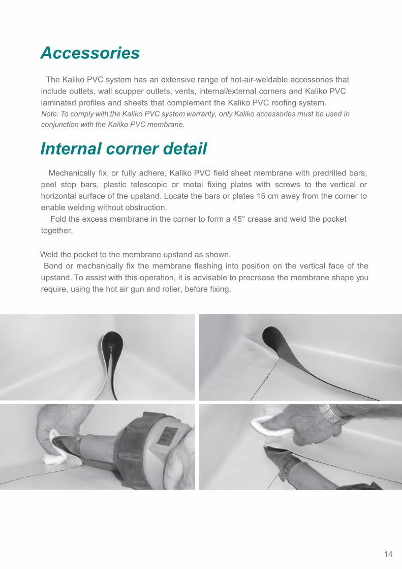
Accessories The Kaliko PVC system has an extensive range of hot-air-weldable accessories that include outlets, wall scupper outlets, vents, internal/external corners and Kaliko PVC laminated profiles and sheets that complement the Kaliko PVC roofing system.Note: To comply with the Kaliko PVC system warranty, only Kaliko accessories must be used in conjunction with the Kaliko PVC membrane.
Internal corner detail Mechanically fix, or fully adhere, Kaliko PVC field sheet membrane with predrilled bars, peel stop bars, plastic telescopic or metal fixing plates with screws to the vertical or horizontal surface of the upstand. Locate the bars or plates 15 cm away from the corner to enable welding without obstruction. Fold the excess membrane in the corner to form a 45° crease and weld the pocket together.
Weld the pocket to the membrane upstand as shown. Bond or mechanically fix the membrane flashing into position on the vertical face of the upstand. To assist with this operation, it is advisable to precrease the membrane shape you require, using the hot air gun and roller, before fixing.
14
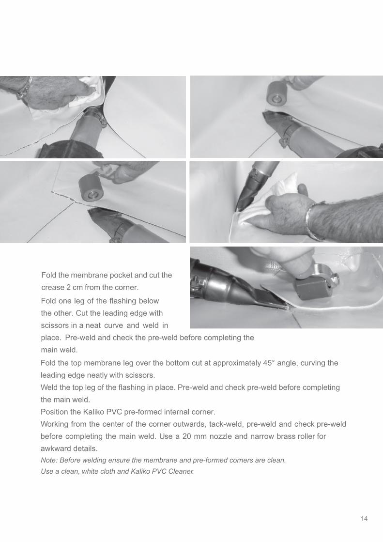
Fold the membrane pocket and cut the crease 2 cm from the corner.
Fold one leg of the flashing below the other. Cut the leading edge with scissors in a neat curve and weld inplace. Pre-weld and check the pre-weld before completing the main weld.Fold the top membrane leg over the bottom cut at approximately 45° angle, curving the leading edge neatly with scissors.Weld the top leg of the flashing in place. Pre-weld and check pre-weld before completing the main weld.Position the Kaliko PVC pre-formed internal corner.Working from the center of the corner outwards, tack-weld, pre-weld and check pre-weld before completing the main weld. Use a 20 mm nozzle and narrow brass roller for awkward details.Note: Before welding ensure the membrane and pre-formed corners are clean.Use a clean, white cloth and Kaliko PVC Cleaner.
14

16
Internal corner with a vertical crease
Mechanically fix, or fully adhere, Kaliko PVC field sheet membrane with pre-drilled bars, peel stop bars or fixing plates with screws to the vertical or horizontal surface of the upstand. Locate the bars or plates 15 cm away from the corner to enable welding without any obstruction.Fold the excess membrane in the corner to form a 45° crease and weld the pocket together.Weld the pocket to the membrane upstand.Cut the length of membrane you are going to use for the upstand and pre-crease the bottom leg using the hot air gun and roller to aid installation.Apply Kaliko C30 contact adhesive to the vertical upstand and to the underside of the membrane flashing taking care not to allow glue to contaminate the area you intend to weld. Allow the adhesive to become tacky before bringing both surfaces together. Weld the first flashing in place.Spot-weld, pre-weld and check pre-weld before completing the main weld.Cut, pre-bend and install the adjoining membrane as previously described.
On PVC membranes with a thickness of 1.5 mm and above, it is necessary to remove the step along the membrane edge where the membranes are welded together. This prevents any risk of capillary action of water along the welding line.For example this procedure is carried out using a Dremel tool and stone grinding wheel as shown.Fold and crease the excess membrane into a pocket and weld together as shown.Fold the membrane back onto the opposite face. Draw a vertical line along the length of the flap in line with the bottom welded leg and neatly cut off the excess with scissors before welding into position.
Complete the corner detail by hot air welding the flap.
Note: Should the glue accidentally enter the area you intend to weld you must remove the glue immediately from the membrane using Kaliko PVC Cleaner. Otherwise the membrane will remain contaminated and will not weld together.
15

Mechanically fix, or fully adhere, Kaliko PVC field sheet membrane, with pre-drilled bars, peel stop bars or fixing plates with screws, to the vertical or horizontal surface of the upstand. Locate the bars or plates 15 cm away from the corner to enable welding without any obstruction.Cut a length of membrane to fit the shape of the upstand. Cut the bottom leg of the flashing to allow it to fold at 90°. Bond or mechanically fix the membrane flashing into position on the vertical face of the upstand. To assist with this operation, it is advisable to pre-crease the membrane shape you require, using the hot air gun and roller, before setting in position.Then spot-weld, pre-weld and check the pre-weld before completing the main weld.Position the Kaliko PVC pre-formed corner and weld in place working from the center outwards. Spot-weld, pre-weld and check pre-weld before completing main weld.The 20 mm nozzle is recommended, in conjunction with a narrow brass roller for awkward details.
Note: On corners other than 90°, use adjustable pre-formed petal corners or form the detail with Kaliko F15 unreinforced membrane.
External corner detail
16
18
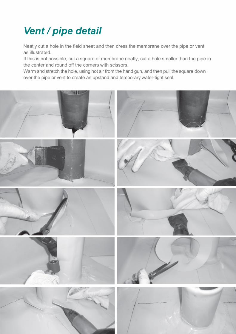
Vent / pipe detailNeatly cut a hole in the field sheet and then dress the membrane over the pipe or vent as illustrated.If this is not possible, cut a square of membrane neatly, cut a hole smaller than the pipe in the center and round off the corners with scissors.Warm and stretch the hole, using hot air from the hand gun, and then pull the square down over the pipe or vent to create an upstand and temporary water-tight seal.
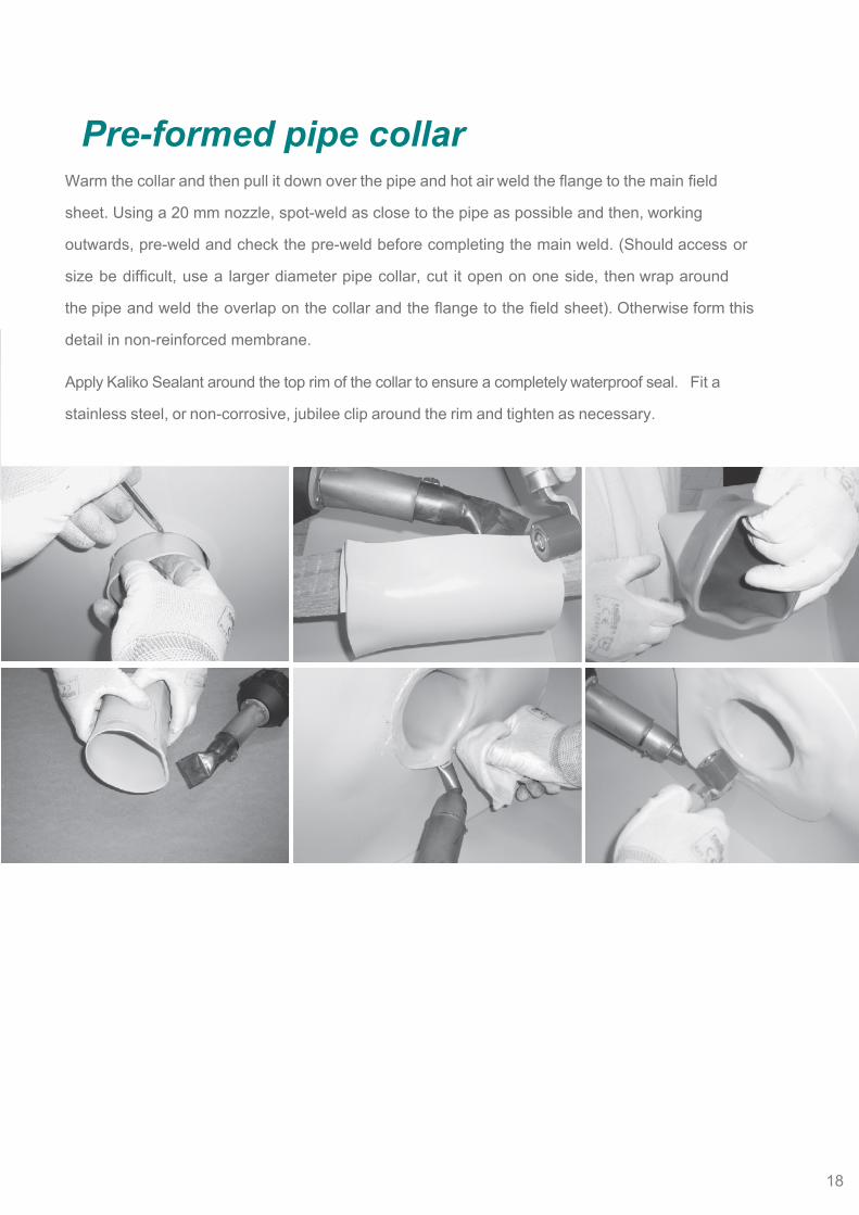
Pre-formed pipe collarWarm the collar and then pull it down over the pipe and hot air weld the flange to the main field
sheet. Using a 20 mm nozzle, spot-weld as close to the pipe as possible and then, working
outwards, pre-weld and check the pre-weld before completing the main weld. (Should access or
size be difficult, use a larger diameter pipe collar, cut it open on one side, then wrap around
the pipe and weld the overlap on the collar and the flange to the field sheet). Otherwise form this
detail in non-reinforced membrane.
Apply Kaliko Sealant around the top rim of the collar to ensure a completely waterproof seal. Fit a
stainless steel, or non-corrosive, jubilee clip around the rim and tighten as necessary.
18

20
Perimeter edge flashing
Kaliko PVC metal laminate is supplied in flat sheets or profiled flashings, 2 meters in length x 1
meter in width.
Mechanically fix the profile trim to the perimeter edge with expansion nails or counter-sunk screws.
At all joints it is necessary to leave a 1 cm gap between the profiles to allow for expansion and
contraction.
To ensure the face of the profile remains straight and square, insert a metal butt strap beneath
the joint making sure it fits tight in to the lip of the drip.
Overlay the gap with 2 cm wide masking tape. This prevents the membrane strip from welding
along the joint.
Weld a 10 cm wide membrane strip to the joint.Note: Do not use domed fixings as they prevent the membrane cover flashings welding flat against the metal.
To assist the welding of the membrane along the top of the Kaliko PVC metal, leave a 1 cm gap
from the front face. Hot air weld the new flashing by spot-welding, pre-welding and checking
the pre-weld before completing the main weld.
Note: Always ensure that the perimeter edge and fixings used can accommodate the wind loadings created. Kaliko PVC metal profiles should be fixed at a maximum of 25 cm fixing centers. Should the front face be deeper than 15cm a secret fix method can be used or additional screws must be inserted into the face of the metal profile.
19
21
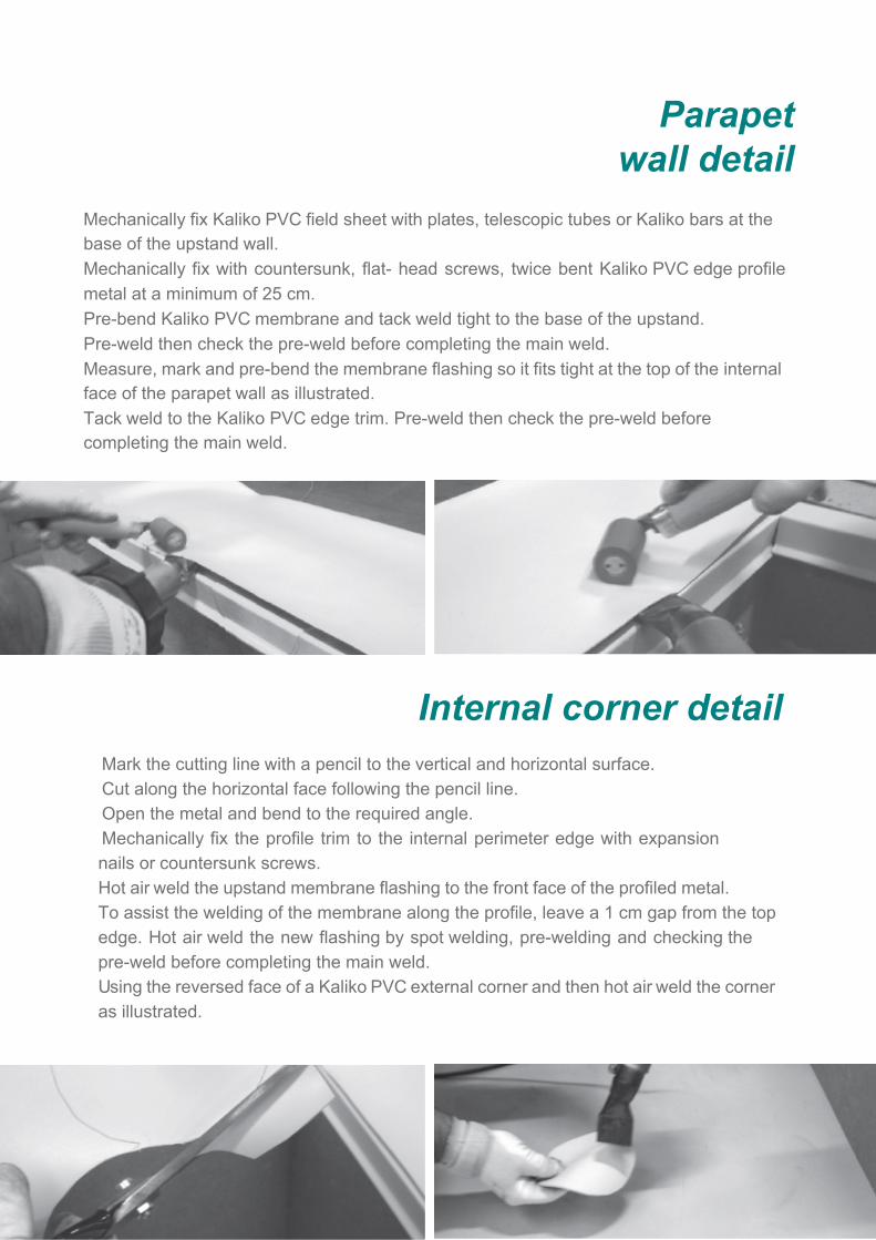
Parapet wall detail
Internal corner detailMark the cutting line with a pencil to the vertical and horizontal surface.Cut along the horizontal face following the pencil line.Open the metal and bend to the required angle.Mechanically fix the profile trim to the internal perimeter edge with expansion nails or countersunk screws.Hot air weld the upstand membrane flashing to the front face of the profiled metal.To assist the welding of the membrane along the profile, leave a 1 cm gap from the top edge. Hot air weld the new flashing by spot welding, pre-welding and checking the pre-weld before completing the main weld.Using the reversed face of a Kaliko PVC external corner and then hot air weld the corner as illustrated.
Mechanically fix Kaliko PVC field sheet with plates, telescopic tubes or Kaliko bars at the base of the upstand wall.Mechanically fix with countersunk, flat- head screws, twice bent Kaliko PVC edge profile metal at a minimum of 25 cm.Pre-bend Kaliko PVC membrane and tack weld tight to the base of the upstand. Pre-weld then check the pre-weld before completing the main weld.Measure, mark and pre-bend the membrane flashing so it fits tight at the top of the internal face of the parapet wall as illustrated.Tack weld to the Kaliko PVC edge trim. Pre-weld then check the pre-weld before completing the main weld.
22
Note: Always ensure that the perimeter edge and fixings used can accommodate the wind loadings created.
Kaliko PVC profile fixing centers must not exceed 25 cm. Do not use domed fixings to secure Kaliko PVC metal profiles as they prevent the membrane cover flashings welding flat against the metal.
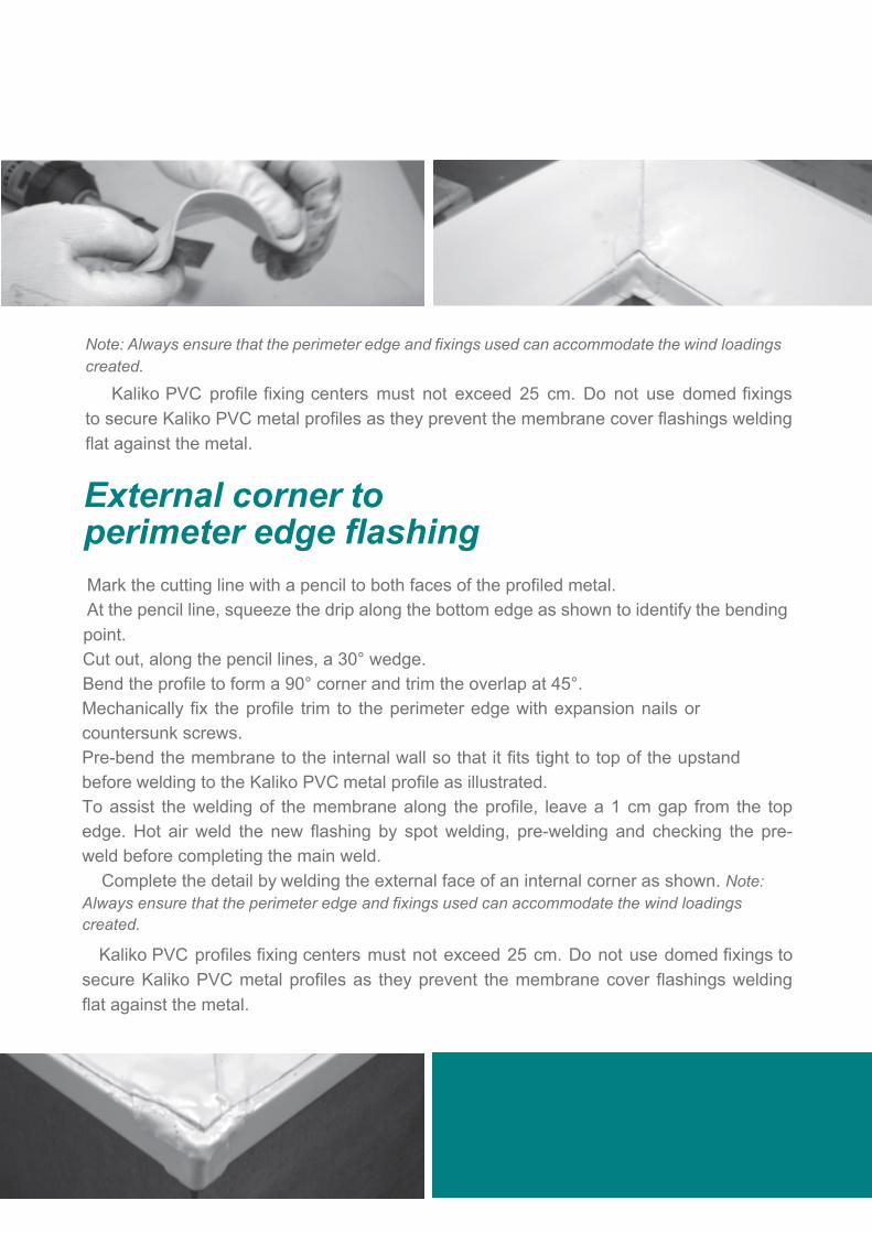
External corner toperimeter edge flashing Mark the cutting line with a pencil to both faces of the profiled metal. At the pencil line, squeeze the drip along the bottom edge as shown to identify the bending point.Cut out, along the pencil lines, a 30° wedge.Bend the profile to form a 90° corner and trim the overlap at 45°.Mechanically fix the profile trim to the perimeter edge with expansion nails or countersunk screws.Pre-bend the membrane to the internal wall so that it fits tight to top of the upstand before welding to the Kaliko PVC metal profile as illustrated.To assist the welding of the membrane along the profile, leave a 1 cm gap from the top edge. Hot air weld the new flashing by spot welding, pre-welding and checking the pre-weld before completing the main weld. Complete the detail by welding the external face of an internal corner as shown. Note: Always ensure that the perimeter edge and fixings used can accommodate the wind loadings created.
Kaliko PVC profiles fixing centers must not exceed 25 cm. Do not use domed fixings to secure Kaliko PVC metal profiles as they prevent the membrane cover flashings welding flat against the metal.
23
Wall termination profile
Seam testing procedure
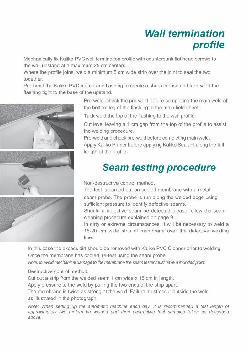
Mechanically fix Kaliko PVC wall termination profile with countersunk flat head screws to the wall upstand at a maximum 25 cm centers.Where the profile joins, weld a minimum 5 cm wide strip over the joint to seal the two together.Pre-bend the Kaliko PVC membrane flashing to create a sharp crease and tack weld the flashing tight to the base of the upstand.
Pre-weld, check the pre-weld before completing the main weld of the bottom leg of the flashing to the main field sheet.Tack weld the top of the flashing to the wall profile.Cut level leaving a 1 cm gap from the top of the profile to assist the welding procedure.Pre-weld and check pre-weld before completing main weld. Apply Kaliko Primer before applying Kaliko Sealant along the full length of the profile.
Non-destructive control method.The test is carried out on cooled membrane with a metal seam probe. The probe is run along the welded edge using sufficient pressure to identify defective seams.Should a defective seam be detected please follow the seam cleaning procedure explained on page 9.In dirty or extreme circumstances, it will be necessary to weld a 15-20 cm wide strip of membrane over the defective weldingline.
In this case the excess dirt should be removed with Kaliko PVC Cleaner prior to welding.Once the membrane has cooled, re-test using the seam probe.Note: to avoid mechanical damage to the membrane the seam tester must have a rounded point.
Destructive control method.Cut out a strip from the welded seam 1 cm wide x 15 cm in length.Apply pressure to the weld by pulling the two ends of the strip apart.The membrane is twice as strong at the weld. Failure must occur outside the weld as illustrated in the photograph.Note: When setting up the automatic machine each day, it is recommended a test length of approximately two meters be welded and then destructive test samples taken as described above.
24
Damage repairs As the membrane has a dark bottom layer, it is easy to see any damage to the mem-brane’s top surface. Should damage occur after installation, or on older membrane, the repairs are simple.Cut a disc of membrane that covers completely the damaged area.Using a pencil, trace around the disc onto the membrane surface.Using a clean white cloth, apply a liberal amount of Kaliko Cleaner to the area and remove the dirt by drawing it off the membrane with the cloth.Once the solvents have flashed off, and the membrane is completely dry, weld the new patch by starting in the center and working out, checking the integrity of the weld as you progress.Note: Do not rub the dirt and the solvent into the membrane. Apply the Cleaner liberally to the weld area then lift off the dirt and Cleaner on to a white cloth. Allow the solvents to flash off before welding.
Welding to an existing PVC membrane
When connecting or joining a new Kaliko PVC membrane system to one previously installed, for example a roof extension make sure the existing membrane is free of dust and dirt. This can be achieved with the use of a water pressure machine or by following the guidelines on page 9 of this manual. Once the membrane is clean and dry, use an automatic welding machine to weld the membranes together.
NoteThe Kaliko Group Ltd has the right to modify or change the text, photographs or details contained in this manual. This is to enable any new or innovative production or practical installation methods to be applied to the manual should they arise.The Kaliko Group Ltd will warranty only the systems and accessories manufactured by the Group. Further, these systems must be installed only by approved contractors and operatives who have undertaken training to install the Kaliko Roofing systems.For all technical guidance on the installation of the KALIKO ROOFING SYSTEMS not covered in this manual, please contact the nearest registered Kaliko technical department.

KALIKO PVC Single Ply General installation guideline
[email protected] www.kalikogroup.co.uk
Tel +44(0) 121 7092522
Flat Roofs with a Future


![Maximizing Strength of Friction Stir Spot Welded ...d.researchbib.com/f/8nnKOup2bho3WaY0yWFx1SY1... · recent times to weld aluminum alloys [5], [6], [7]. Friction stir spot welding](https://img.dokumen.tips/doc/110x75/5f099a157e708231d4279dfb/maximizing-strength-of-friction-stir-spot-welded-d-recent-times-to-weld-aluminum.jpg)


![[Welding] Weld Calculation](https://img.dokumen.tips/doc/110x75/577ce4a51a28abf1038ed313/welding-weld-calculation.jpg)