Embed Size (px)
Citation preview

Introducing the …..Introducing the …..
Flex-Mate

The purpose of the Flex-Mate K500 is to provide continuous passive motion to the knee or hip joint to increase range of motion (ROM), circulation, and to prevent scarring in the joint.
The Flex-Mate K500 is an anatomically aligned CPM which mirrors the path of the knee as it goes through its range of motion from full or hyper-extension through full flexion.
Product DescriptionProduct Description

• Use only manufacturer approved parts and maintenance procedures to service the unit. Refer to the Flex-Mate K500 Service Manual.
• Read and adhere to all warnings and instructions listed on the Flex-Mate K500 and in the Users Manual.
• If you suspect the Flex-Mate K500 is not working properly, unplug the unit and refer to the Service Manual.
• If you detect a flaw of any type in the power cord, immediately unplug the transformer from the wall.
• Use only the external power supply provided with the Flex-Mate K500 in order to meet the requirement of UL 60601-1.
Safety PrecautionsSafety Precautions

Selected SpecificationsSelected Specifications
Standard Configuration Pediatric Configuration
30.5 - 42 in. (77 – 107cm) Limb Length
0 – 30 seconds at maximum extension/flexionPause
UL/C-UL ; UL 60601-1, UL 1431CSA C22.2 / No. 601.1
Safety-10° extension to 120° flexionRange of MotionApproximately 26 lbs.Weight

Standards Compliance: Designed to conform to applicablerequirements of:UL 60601-1, UL 1431CSA C22.2 / No. 601.1
Size Setup for Use:Length 39”Width 13”Height 22”
Weight:Without accessories 26 lbsWith accessories 27 lbsFully packaged 34 lbs
Electrical Specifications:Input 120 VAC 60Hz 25W
Physical and Electrical SpecificationsPhysical and Electrical Specifications

Flex-Mate K500 - OverviewFlex-Mate K500 - Overview
• Please familiarize yourself with all the components and the operation of the Flex-Mate K500 device prior to setting up a patient or beginning therapy.
Flex-Mate K500 Knee CPM

Package Contents:Package Contents:
• 1 Flex-Mate K500 CPM• 1 Users Manual• 1 Service Manual• 1 Package of soft goods (4- pieces)• 1 Tape measure• 1 Small bottle of lubricating oil

Flex-Mate K500 - OverviewFlex-Mate K500 - OverviewFeatures:
• Programmable R.O.M. � (-10° Full ext - 120° Full flex)
• Anatomical motion• Lightweight design (26 lbs.)• Easy patient set-up• User friendly controls• Patient Lock-out feature• Integrated carrying handle• Universal left / right design• High quality soft goods that are easy to attach• TKR / ACL / adult / pediatric / sports medicine
applicable• Adult / pediatric foot cradle conversion• Ideal for home & hospital settings

Foot Pad
Femur Pad
Foot Plate
Tibial Carriage
Hand-held ControllerCarrying Handle
Femoral Carriage
Femur Scale
Tibial Pad Thigh Strap (not shown)
Power On/Off Switch
(on back of unit)
Product OverviewProduct Overview
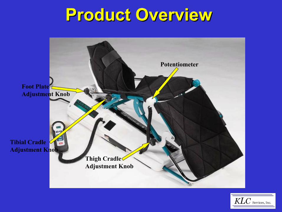
Foot Plate Adjustment Knob
Tibial Cradle Adjustment Knob
Potentiometer
Thigh Cradle Adjustment Knob
Product OverviewProduct Overview
Top Side
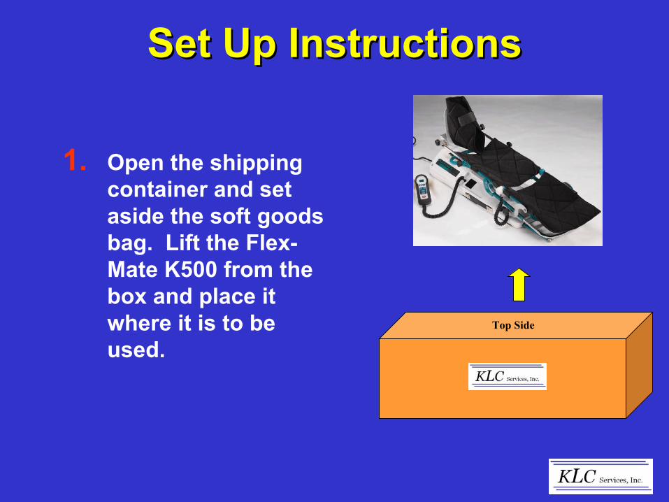
Set Up InstructionsSet Up Instructions
1. Open the shipping container and set aside the soft goods bag. Lift the Flex-Mate K500 from the box and place it where it is to be used.

Set Up InstructionsSet Up Instructions2. Plug the wall
transformer into a grounded 110/120 volt AC wall outlet close to the machine.
Note: (Use of an extension cord is not recommended)
3. Locate the power switch (at the back of unit) and press to the “On” position.
Transformer
On/Off Switch
Grounded Wall Outlet

Set Up InstructionsSet Up Instructions
4. Upon turning the unit “On” you should hear and audible beep and the LCD Display should “light up” on the Control Pendant
LCD Display

Set Up InstructionsSet Up Instructions5. Using the hand-held
controller, press theStart/Stop button.
• Bring the machine to between 45° and 90° of flexion. (See Hand-held Controller Operating instructions.
• This allows the soft goods to be applied easier.
Control Pendant
(45° - 90°) Flexion
Start/Stop Button

Flex-Mate Soft Good Kit(Back Side)
Flex-Mate Soft Good Kit(Back Side)
Boot
Tibial PadFemoral Pad
Auxiliary Strap(Wraps around Thigh)
6. Open the bag containing the soft good kit and identify the different pieces that make up the kit.
Note: There are (3) Velcro straps on the Tibial pad and (2) on the Femoral pad.
1 2 3 1 2
Pillow

Set Up InstructionsSet Up Instructions
7. Secure the patient pads to the machine.
• The foot pad has a pocket that slips over the Foot Plate.
• The Tibia and Femoral pads have Velcro straps that fit around the corresponding cradle and secure to the back side of the pad itself.
Foot Pad (Boot)
Tibial Pad
Femur PadVelcro Straps

Set Up InstructionsSet Up Instructions8. Next (using the tape
measure provided) measure the patient’s involved leg.
• Measure in centimeters from the hip joint to the midline of the knee joint.
• This measurement will be transferred to the femoral carriage of the device.
(Hip Joint)
(Joint line of Knee)

Set Up InstructionsSet Up Instructions
9. Loosen the femoral knobs on each side of the device.
• Adjust the femoral cradle so the measurement of the patients leg (centimeters) matches that on the femur scale. (both sides)
• Retighten the femoral knobs.
Femur Scale
Femoral Knob
Femur Scale in centimeters

Set Up InstructionsSet Up Instructions10.Next - Loosen the
adjustment knobs on the tibial cradle.
• Slide the foot plate out to a length greater than the patient’s lower leg.
Note: You can either “eye-ball” or actually measure the patient’s affected limb from the joint line of the knee to the heel of the foot.
Tibial Adjustment Knob
(Joint line of Knee)
(Base of Heel)

Set Up InstructionsSet Up Instructions11.Prior to starting the
machine, follow the Hand-held Controller Operating instructions to set the flexion, extension, speed and pause duration to the doctors prescribed settings.
• Without the patient in the device, Start the unit and run a complete cycle to ensure that it functions properly.
Users Manual
Run a complete cycle

Set Up InstructionsSet Up Instructions12.When ready to place the
patient’s leg into the CPM carriage, press Start/Stop on the control pendant.
• Allow the device to run until it reaches 0° of extension or until the leg carriage is straight.
• This makes putting the patient’s leg into the carriage easier and typically is more comfortable for the patient, as well.
0° or Straight
Start/Stop

1. Set Range of Motion
• Hold down “FLEX” or “EXT” button and simultaneously press the “UP” or “DOWN”arrow button to set the limits.
• Upon releasing the “UP”or “DOWN” arrows this becomes the end parameter setting.
• Full range is from -10°extension to 120°flexion.
Hand-held Controller OperationHand-held Controller Operation
“EXT” and “UP”or “DOWN”
(Simultaneously)
“FLEX” and “UP” or “DOWN”
(Simultaneously)

2. Set Speed
• Hold down “SPEED” and simultaneously press the“UP” or “DOWN” arrow to set speed.
• Upon releasing the “UP” or “DOWN” arrows this becomes the end parameter setting.
• Speed can be adjusted in 10 degree increments ranging from 30° (slow) per minute to 150° (fast) per minute.
Hand-held Controller OperationHand-held Controller Operation
“SPEED” and “UP”or “DOWN”
Depress Simultaneously

3. Set Pause
• Hold down “DELAY” and simultaneously press the “UP” or “DOWN” arrow to set the length of time the unit will pause at the flexion and extension limits. (It will pause at both limits)
• Upon releasing the “UP” or “DOWN” arrows this becomes the end parameter setting.
• Delay range is from 0 seconds to 30 seconds.
Hand-held Controller OperationHand-held Controller Operation
“SPEED” and “UP”or “DOWN”
Depress Simultaneously

4. Begin Motion
• Press “START/STOP” to begin motion.
• Press “START/STOP”again to stop motion.
Note: Upon restarting the unit it will move in the opposite direction than prior to stopping.
Hand-held Controller OperationHand-held Controller Operation
Press “START/STOP”to begin or stop motion

5. Set Lock-out
• Press both the “UP” and “DOWN” arrows at the same time to lock the settings, and again to unlock.
• When locked, a dot will show in the lower right corner of the display.
Note: Lock-out mode is retained even when power is turned off.
Hand-held Controller OperationHand-held Controller Operation
Press “START/STOP”to begin or stop motion
Depress Simultaneously
“Lock out” Dot

6. Simplified Instructions
• Are located on the backside of the control pendant for easy reference.
• Instructions for setting Flexion, Extension, Speed, Pause, and Start/Stop are listed.
Hand-held Controller OperationHand-held Controller Operation

Set Up Instructions(Positioning the Patient)
Set Up Instructions(Positioning the Patient)
1. The machine is now ready to be fit to the patient and to begin rehabilitation.
• With the patient lying on the bed, couch or floor -support and then lift the patients affected leg.
• Slide the unit under the patients affected limb and then place into the carriage of the device.
Note: This is easier to do with two people helping.

2. Upon placing the patients leg in the machine, make sure the patients knee is aligned with the joint or center axis of the machine. Align patients knee axis – to center axis of device
Knee Axis
Set Up Instructions(Positioning the Patient)
Set Up Instructions(Positioning the Patient)

3. Adjust the length of the tibial carriage so the footplate meets the sole of the patient’s foot.
• You should be able to place your fingers between the bottom of the patient’s foot and the footplate.
• Tighten the Tibial Carriage adjustment knobs.
Tibial carriage length adjustment
Fingers width between footplate and patients foot
Tighten Knobs
Set Up Instructions(Positioning the Patient)
Set Up Instructions(Positioning the Patient)
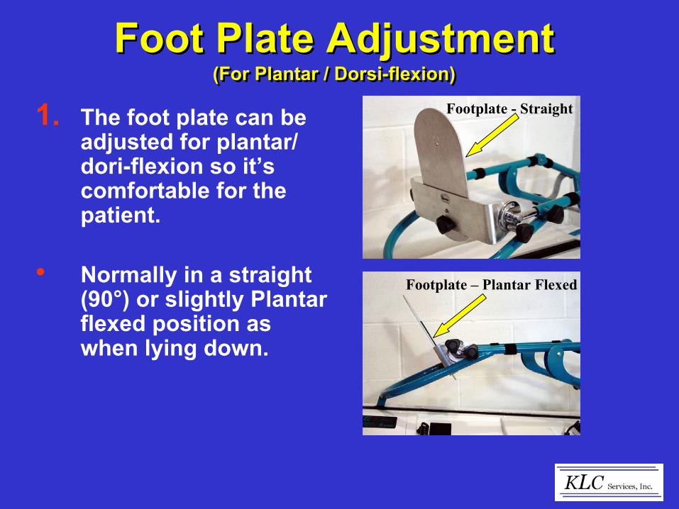
1. The foot plate can be adjusted for plantar/ dori-flexion so it’s comfortable for the patient.
• Normally in a straight (90°) or slightly Plantar flexed position as when lying down.
Footplate - Straight
Footplate – Plantar Flexed
Foot Plate Adjustment(For Plantar / Dorsi-flexion)
Foot Plate Adjustment(For Plantar / Dorsi-flexion)

Foot Plate Adjustment(For Plantar / Dorsi-flexion)
Foot Plate Adjustment(For Plantar / Dorsi-flexion)
A. Plantar / Dorsi-flexion
• Loosen the adjustment knobs on each side of the foot plate.
• Adjust the foot plate to the desired degree of plantar or dorsi-flexion.
• Retighten knobs.
Plantar Flexed
Dorsi-Flexed
Adjustment Knob
Adjustment Knob

1. The foot plate can also be rotated internally or externally for patient comfort or to help the leg from rotating in the carriage.
• This allows the device to track the axis of the patients knee more accurately.
• Ultimately this provides a truer therapy.
Everted
Inverted
Adjustment Knob
Adjustment Knob
Foot Plate Adjustment(For Internal / External rotation)
Foot Plate Adjustment(For Internal / External rotation)

Everted
Inverted
Adjustment Knob
Adjustment Knob
Foot Plate Adjustment(For Internal / External rotation)
Foot Plate Adjustment(For Internal / External rotation)
A. Internal / External Rotation
• Loosen the adjustment knob on the foot plate.
• Adjust the foot plate to the prescribed degree of internal/external rotation.
• Retighten knob.

Note: In situations where you are fitting a small adult or pediatric patient then you might need to convert the foot cradle for this type of application.
• This will allow you to more accurately fit the patient and provide a better overall therapy.
Foot Plate Adjustment(For Pediatric or Small Adult tibial length)
Foot Plate Adjustment(For Pediatric or Small Adult tibial length)
Adult – Set Up
Pediatric – Set Up

1. Remove the adjustment knob on the bottom (back) of the foot plate.
• Next, remove the foot plate itself.
Foot Plate Adjustment(For Pediatric or Small Adult tibial length)
Foot Plate Adjustment(For Pediatric or Small Adult tibial length)
Remove Knob
Remove Footplate
Footplate Removed

2. Rotate the foot plate bracket inward 180° as shown.
Foot Plate Adjustment(For Pediatric or Small Adult tibial length)
Foot Plate Adjustment(For Pediatric or Small Adult tibial length)
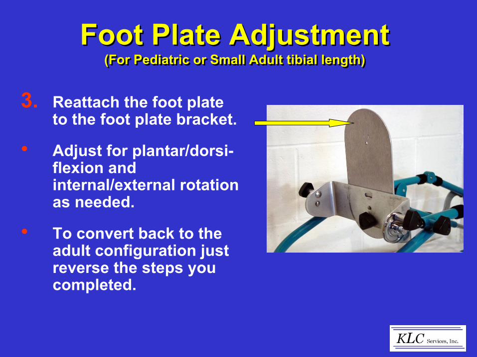
3. Reattach the foot plate to the foot plate bracket.
• Adjust for plantar/dorsi-flexion and internal/external rotation as needed.
• To convert back to the adult configuration just reverse the steps you completed.
Foot Plate Adjustment(For Pediatric or Small Adult tibial length)
Foot Plate Adjustment(For Pediatric or Small Adult tibial length)

Set Up InstructionsSet Up Instructions
• Wrap the Auxiliary (thigh) strap around the patients thigh and the femoral carriage of the device.
• This helps secure the patient’s leg in the carriage of the Flex-Mate K500 and keep the knee axis in line with the axis of the machine.
Auxiliary Strap
Apply strap around patients thigh and femoral cradle
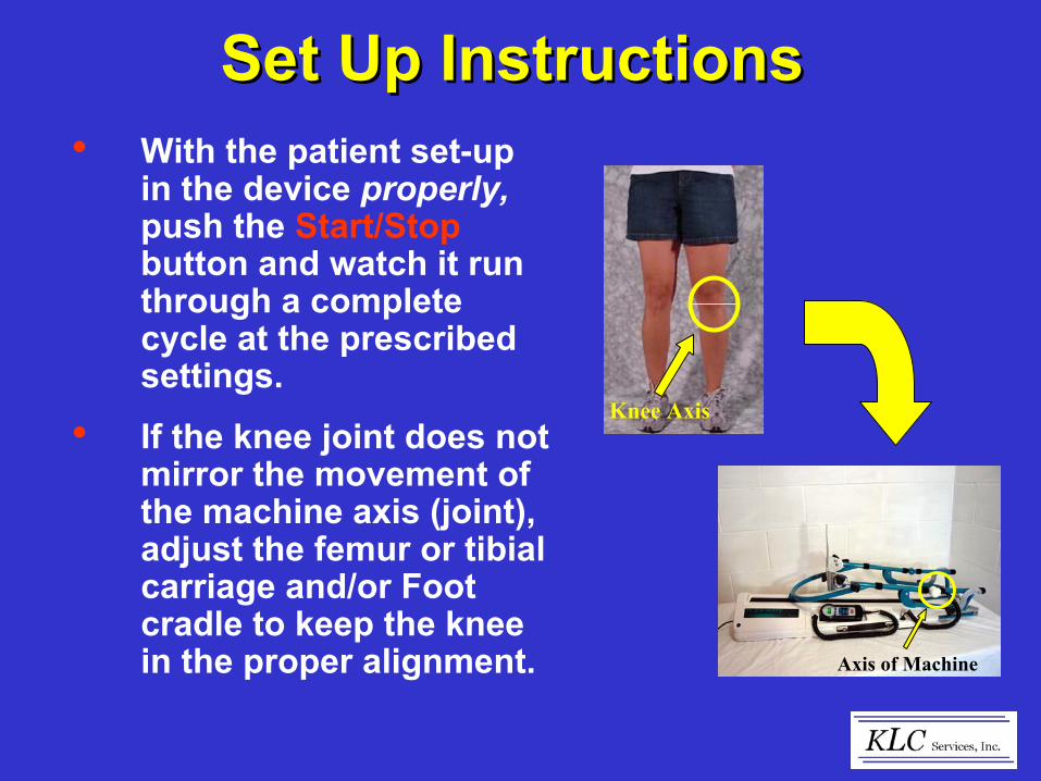
Set Up InstructionsSet Up Instructions• With the patient set-up
in the device properly, push the Start/Stopbutton and watch it run through a complete cycle at the prescribed settings.
• If the knee joint does not mirror the movement of the machine axis (joint), adjust the femur or tibial carriage and/or Foot cradle to keep the knee in the proper alignment.
Knee Axis
Axis of Machine

1. Hospital Bed Fixture
• The Flex-Mate K500 Hospital Bed Fixture may be purchased optionally to attach the K500 to a hospital bed utilizing a standard hospital traction clamp.
• The Hospital Bed Fixture is used to provide additional stability of the unit while used in a bed.
Optional AccessoriesOptional Accessories
Hospital Bed Mount

2. Hospital Bed Fixture
• Attach the Hospital Bed Fixture to the K500 by sliding the fixture into the tubes located at the end of the K500 as shown.
• Insert and tighten the knobs included with the fixture as shown.
Optional AccessoriesOptional AccessoriesFixture Tubes
Knobs
Slide Fixture into Tubes
Tighten Knobs
Hospital Bed Fixture

3. Hospital Bed Fixture
• Position the K500 on the bed in the appropriate position and attach to a bed mounted traction bar using standard traction fittings.
Note: Do not carry the K500 by the Hospital Bed Fixture.
Optional AccessoriesOptional Accessories

• With unit unplugged – clean housing and leg carriage with a mild soap solution and dry thoroughly.
• Refer to the Service Manual for recommended maintenance.
CAUTION: Avoid getting water inside the housing as it may damage the electrical components.
Cleaning and MaintenanceCleaning and Maintenance

Monthly
• Inspect general condition of unit. (frayed cords, housing integrity, Velcro, belt wear) replace as necessary.
• Apply 3 drops of oil (provided in box of new unit) to the oiling felt located in the nut housing.
• Clean housing & leg carriage with a mild soap solution and dry.
Routine MaintenanceRoutine Maintenance
Oiling Instruction Label
Location of oiling felt in nut housing

Basic Troubleshooting(During Warranty Period)
Basic Troubleshooting(During Warranty Period)
Refer to User’s Manual regarding locking feature.Cannot change pendant settings.
Check pendant settings.Check belts.
Unit will not start, or it starts then stops
Check all connections at the P.C. Board.Pendant adjustments inoperative, but display on.
Turn power off, wait 5 seconds, and turn power back on.Pendant displays “Err”.
Check that the wall outlet has power.Check power switch-on.
No pendant display.
NOTE: If the above solutions do not work or for other problems not listed, call KLC Services, Inc. Any actions other than those listed above will void the warranty.

KLC Services, Inc.Corporate Head Quarters4038 Weaver Court EastHilliard, OH 43026USA
(866) 532 - 3534 (Free)(614) 921 - 8866 (Ph)(614) 921 - 8877 (Fx)
Mark Reep Kay ReepCPM Sales Mgr. Office [email protected] [email protected]
Website: www.klcflexmate.com
Contact InformationContact Information

Strength Through MotionStrength Through Motion
Flex-Mate