Embed Size (px)
Citation preview

EE Krash (Sample)
© Kreatryx. All Rights Reserved. www.kreatryx.com
Control Systems
Root Locus Technique
Root – Loci is important to study trajectories of poles and zeroes as the poles & zeroes
determine transient response & stability of the system.
Characteristic equation
1+G(s)H(s)=0
Assume G(s)H(s) =
Condition of Root locus
,
,
The difference between the sum of the angles of the vectors drawn from the zeroes and
those from the poles of G(s) H(s) to s1 is an odd multiple of 180° if K > 0.
The difference between the sum of the angles of the vectors drawn from the zeroes and
those from the poles of G(s) H(s) to s1 is an even multiple of 180° if K < 0. This is called as
Complimentary Root Locus.
Properties of Roots loci of
1. K = 0 points: These points are poles of G(s)H(s), including those at s = .
2. K = points: The K = points are the zeroes of G(s)H(s) including those at s = .
3. Total numbers of Root loci is equal to order of equation.
4. The root loci are symmetrical about the axis of symmetry of the pole- zero configuration
G(s) H(s).
5. For large values of s, the RL (K > 0) are asymptotes with angles given by:
For CRL(complementary root loci) (K < 0)
where i = 0, 1, 2, ……….,
1 1KG s H s
1 11 KG s H s 0
1 11G s H s
K
1 1
1G s H s k magnitude criterion
k
1 1G s H s 2i 1 odd multiples of 180 angle critK 0 erion
1 1G s H s 2i even multiples oK f 1800
1 11 KG s H s 0
1 11 KG s H s 0
i
2i 1180
n m
i
2i180
n m
n m 1
K-Notes

EE Krash (Sample)
© Kreatryx. All Rights Reserved. www.kreatryx.com
n = number of finite poles of G(s) H(s)
m = number of finite zeroes of G(s) H(s)
6. The intersection of asymptotes lies on the real axis in s-plane. The point of intersection is
called centroid ( ) =
7. Root locus is found in a section of the real axis only if total number of poles and zeros to
the right side of section is odd if K > 0. For CRL (K < 0), if the number of real poles & zeroes
to right of given section is even, then that section lies on root locus.
8. The angle of departure or arrival of roots loci at a pole or zero of G(s) H(s) say s1 is found
by removing term (s – s1) from the transfer function and replacing ‘s’ by ‘s1’ in the remaining
transfer function to calculate
It can also be calculated as
Angle of Departure (only applicable for poles) = 1800 +
Angle of Arrival (only applicable for zeroes) = 1800 -
For Complimentary Root Locus,
Angle of Departure (only applicable for poles) = 00 +
Angle of Arrival (only applicable for zeroes) = 00 –
9. The crossing point of root-loci on imaginary axis can be found by equating coefficient of
s1 in Routh table to zero & calculating K.
Then roots of auxiliary polynomial give intersection of root locus with imaginary axis.
10. Break-away & Break-in points
These points are determined by finding roots of . On substituting, if K>0, only then it
is a valid breakaway/break-in point.
For breakaway points :
For break in points :
A breakaway point lies between consecutive poles and break in point lies between two
consecutive zeroes.
11. Value of K on Root locus is
The value of gain at any point on root locus can be determined geometrically as,
1
real parts of poles G(s)H(s) real parts of zeroes G(s)H(s)
n m
1 1
G s H s
1 1Angle of s from zeroes Angle of s from poles
1 1
G s H s
1 1
G s H s
1 1
G s H s
1 1
G s H s
dK
0ds
2
2
d K0
ds
2
2
d K0
ds
1 11 1
1K
G s H s
Pr oduct of vector length of polesK
Pr oduct of vector length of zeroes

EE Krash (Sample)
© Kreatryx. All Rights Reserved. www.kreatryx.com
Addition of poles & zeroes to G(s) H(s)
Addition of a pole to G(s) H(s) has the effect of pushing of root loci toward right half
plane & hence stability decreases.
Addition of left half plane zeroes to the function G(s) H(s) generally has effect of moving
& bending the root loci toward the left half s-plane & hence stability increases.
Signal Flow Graphs
Node: It represents a system variable which is equal to sum of all incoming signals at it.
Outgoing signals do not affect value of node.
Output node: Node having only incoming branches
Input node: Node having only outgoing branches
Loop: It is a path which originates & terminates at the same node.
Branch: A signal travels along a branch from one node to another in the direction
indicated by the branch arrow & in the process gets multiplied by gain or transmittance
of branch
Forward Path: Path from input node to output node.
Non-Touching loops: Loops that do not have any common node.
Mason’s Gain Formula
Ratio of output to input variable of a signal flow graph is called net gain.
= path gain of kth forward path
= determinant of graph = 1 – (sum of gain of individual loops)
+ (sum of gain product of 2 non touching loops)
– (sum of gain product of 3 non touching loops) +………
= gain product of all ‘r’ non touching loops.
= the value of obtained by removing all the loops touching kth forward path.
T = overall gain
Example :
Forward path ,
k kK
1T P
kP
m1 m2 m3K
1 P P P ............
mrP
K
P G G G G1 1 2 3 4 P G G
2 1 5

EE Krash (Sample)
© Kreatryx. All Rights Reserved. www.kreatryx.com
To find :
Individual loops , ,
, ,
Non – Touching loops (2) ,
Since, both forward paths touch all loops,
Gain =
Tip: For objective type questions, always prefer Mason’s gain formula instead of block
diagram reduction for finding transfer function.
Effect of Feedback
Due to negative feedback the gain reduces and due to positive feedback the gain
increases.
Feedback can improve stability or be harmful to stability if not applied properly.
Eg. Gain = & GH = –1, output is infinite for all inputs.
Sensitivity
Sensitivity is the ratio of relative change in output to relative change in input
For open loop system
T=G
For closed loop system
(Sensitivity decreases)
Thus, by the use of feedback sensitivity of Transfer Function w.r.t. forward gain reduces.
Sensitivity w.r.t. feedback path is,
L G H1 2 2 L G H
2 4 4
L H3 3 L G G G H
4 2 3 4 1 L G H
5 5 1
L' L L G H G H1 1 2 2 2 4 4
L' L L G H H2 1 3 2 2 3
1 G H G H H G G H G G H G H G H G H H2 2 4 4 3 2 3 1 4 5 1 2 2 4 4 2 2 3
11 2
Y P P5 1 1 2 2
Y1
G G G G G G1 2 3 4 1 5
G
1 GH
TG
TTS
GG
TG
G T GS 1 1
T G G
GT
1 GH
TG 2
G 1 GHG T 1 1S 1
T G G 1 GH1 GH
T T H TTSH H H T H
2T G
2H 1 GH

EE Krash (Sample)
© Kreatryx. All Rights Reserved. www.kreatryx.com
If GH ≫ 1
This implies that effect of variation in H is not reduced even in a closed loop system so
change in feedback parameter is undesirable. Also, the closed loop control system is more
sensitive to changes in feedback elements than forward path elements.
Effect of disturbance (noise) signals
: Response due to noise input
: Response due to applied input
To minimize , we need to increase so effect of noise can be reduce by increasing the
gain of path (forward) earlier to noise.
Due to feedback the gain of noise decreases.
Note: Transfer function can only be written for single input & single output system. Hence,
for finding CR , assume N=0 & for finding CN , assume R=0.
Type and Order of a System
The number of poles of an Open Loop Transfer Function at origin is termed as Type of the
System.
The highest power of ‘s’ in Characteristic Equation or the denominator of Closed Loop
Transfer Function is called as Order of the system.
Characteristic Equation is given as, 1+G(s)H(s) = 0
2 H 1 GHGTSH 2 G1 GH
GH
1 GH
TS 1H
C C CN R
CN
CR
G G1 2C R
R 1 G G H1 2
G2C N
N 1 G G H1 2
CN
G1

EE Krash (Sample)
© Kreatryx. All Rights Reserved. www.kreatryx.com
Signal & Systems
Fourier Transfoem
Fourier series exists only for periodic signals, Fourier series converges to Fourier Transform
which is continuous as compared to Fourier series which is discrete.
Continuous Time Fourier Transform
Analysis equation : j tX j x t e dt
Synthesis equation : j t1x t X j e d
2
Properties of Continuous Time Fourier Transform
Linearity 1 2 1 2
F.T.ax t bx t aX bX
Time shifting 0j t
0
F.T.x t t e X
Frequency shifting 0j t
0 0
F.T.x t e X or X f f
Time scaling F.T. 1
x at Xaa
Duality F.T.X t 2 x or x f
Time reversal F.T.x t X or X f
Differentiation in time domain F.T.d
x t j X or j2 fX fdt
Differentiation in frequency
domain F.T. d
tx t j Xd
F.T. dj2 tx t X f
df
Integration in time domain
t
F.T.X
x d X 0 if X 0 0j
Conjugate * * *F.T.x t X or X f
Convolution in time domain 1 2 1 2
F.T.x t * x t X X
Convolution in frequency domain 1 2 1 2
F.T. 1x t .x t X * X
2
Parseval’s power theorem
21x t dt X d
2
Area under signal x t X 0 x t dt
and 1
x X 0 X d2
EE Krash (Sample)
© Kreatryx. All Rights Reserved. www.kreatryx.com
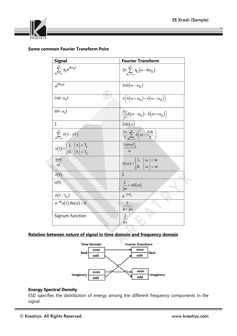
Some common Fourier Transform Pairs
Signal Fourier Transform
0jk t
kK
a e
0kk
2 a k
0jk te
02
cos 0t
0 0
sin 0t
0 0j
1 2
n
t nT
K
2 2 k
T T
1
1
1, t Tx t
0, t T
1
2sin T
sint
t
1, wx
0, w
t 1
u(t)
1
j
0t t 0j t
e
ate u t ,Re a 0 1
a j
Signum function 2
j
Relation between nature of signal in time domain and frequency domain
Energy Spectral Density
ESD specifies the distribution of energy among the different frequency components in the
signal.

EE Krash (Sample)
© Kreatryx. All Rights Reserved. www.kreatryx.com
ESD, 2
( ) X( )
E = 2 21
x(t) dt X( ) d2
=
2
X(f) df
Power spectral density (PSD)
PSD defines distribution of power in the signal.
2
T
X fS lim
T
Fourier Transform of periodic signal
0jn t
nn
f t C e
0n
nF 2 C n
0n
nF 2 C n
So Fourier transform spectrum of periodic signals is always discrete.
Discrete Time Fourier Transform (For ECE)
The discrete-time Fourier transform (DTFT) or the Fourier transform of a discrete–time
aperiodic sequence x[n] is a representation of the sequence in terms of the complex
exponential sequence ejωn
DTFT
Discrete Continuous
j j x n XX e or X e
As in Fourier transform, jX e is also called spectrum and is a continuous function of the
frequency parameter ω and is a periodic function of frequency with period 2 .
j j n
n
X e x n e
Analysis equation
The infinite series in equation 1 may be converges or may not. x[n] is absolutely summable.
n
When x n
An absolutely summable sequence has always a finite energy but a finite-energy sequence is
not necessarily to be absolutely summable.
Inverse Discrete Time Fourier Transform
j j n
2
1x n X e e d
2
Synthesis equation
Properties of DTFT
(i) Linearity
If DTFT j
1 1x n X e and DTFT j
2 2x n X e

EE Krash (Sample)
© Kreatryx. All Rights Reserved. www.kreatryx.com
(ii) Time shifting
If DTFT jx n X e
0j nDTFT j
0Then x n n e X e
(iii) Frequency shifting
If DTFT jx n X e
0 0j n j( )DTFTThen x n e X e
(iv) Time Scaling
If DTFT jx n X e
DTFT j knThen x X e
k
(v) Time Scaling
If DTFT jx n X e
DTFT j knThen x X e
k
(vi) Conjugate
If DTFT jx n X e
Then * DTFT * jx n X e
(vii) Frequency differentiation
If DTFT jx n X e
Then DTFT jdnx n j X e
d
(viii) Convolution in n-domain
If DTFT j DTFT j
1 1 2 2x n X e and x n X e
Then DTFT j j
1 2 1 2x n x n X e X e
(ix) Windowing or modulation property
If DTFT j DTFT j
1 1 2 2x n X e and x n X e
Then j pDTFT j j jp
1 2 1 2 1 2
1 1x n x n X e * X e or X e X e dp
2 2

EE Krash (Sample)
© Kreatryx. All Rights Reserved. www.kreatryx.com
(x) Periodicity
If DTFT jx n X e
j 2 k jThen x e x e
(xi) First difference:
If DTFT jx n X e
DTFT j jThen x n x n 1 1 e x e
(xii) Parseval’s theorem:
If DTFT jx n X e
2
2j
n 2
1Then x n X e d
2
Distortion less transmission through LTI system
For distortion less transmission, output response must be exact replica of input response.
0y t kx t t
0j tY e kX
0j tY
keX
0
H K
H n t
So the conditions for Distortion less Transmission through a LTI System are:
Magnitude response must be constant.
Phase response must be linear.
Hilbert transform
Hilbert transform of a signal x(t) is defined as the transform in which phase angle of all
components of the signal is shifted by ±900. Hilbert transform of x(t) is represented by x t .
Correlation
Correlation is a measure of similarity between two signals. It is used in RADAR or SONAR to
measure similarity between the transmitted signal and the signal received after reflection.
Types of correlation
1. Cross correlation function (CCF)
2. Auto correlation function (ACF)
Cross correlation function
Cross correlation is the measure of similarity between two different signals.
* *
XYR x t .y t dt x t y t dt

EE Krash (Sample)
© Kreatryx. All Rights Reserved. www.kreatryx.com
Auto correlation function
Correlation is said to be cross correlation if similarity between a signal and its shifted version.
For Energy signal
* *
XXR x t .x t dt x t x t dt
For Power signal
T
*
xT
T
1R Lt x t .x t dt
2
T
TT
1Lt x t x * t dt
2
Properties of ACF
(i) ACF is an even function of “ ” i.e. XX XXR R
(ii) ACF has its maximum magnitude at origin i.e. XX XXR R 0
(iii) 2
XXR 0 x t dt
Energy in x(t)
T
2
TT
1Lt x t dt
2T
Average power in x(t)
(iv) 2 21
x t dt X d2
2
x f df
Where 2
X Power spectral density (PSD)
(v) 2
XX XX XX
F.T.R S S X PSD
EE Krash (Sample)
© Kreatryx. All Rights Reserved. www.kreatryx.com
Engineering Maths
Calculus
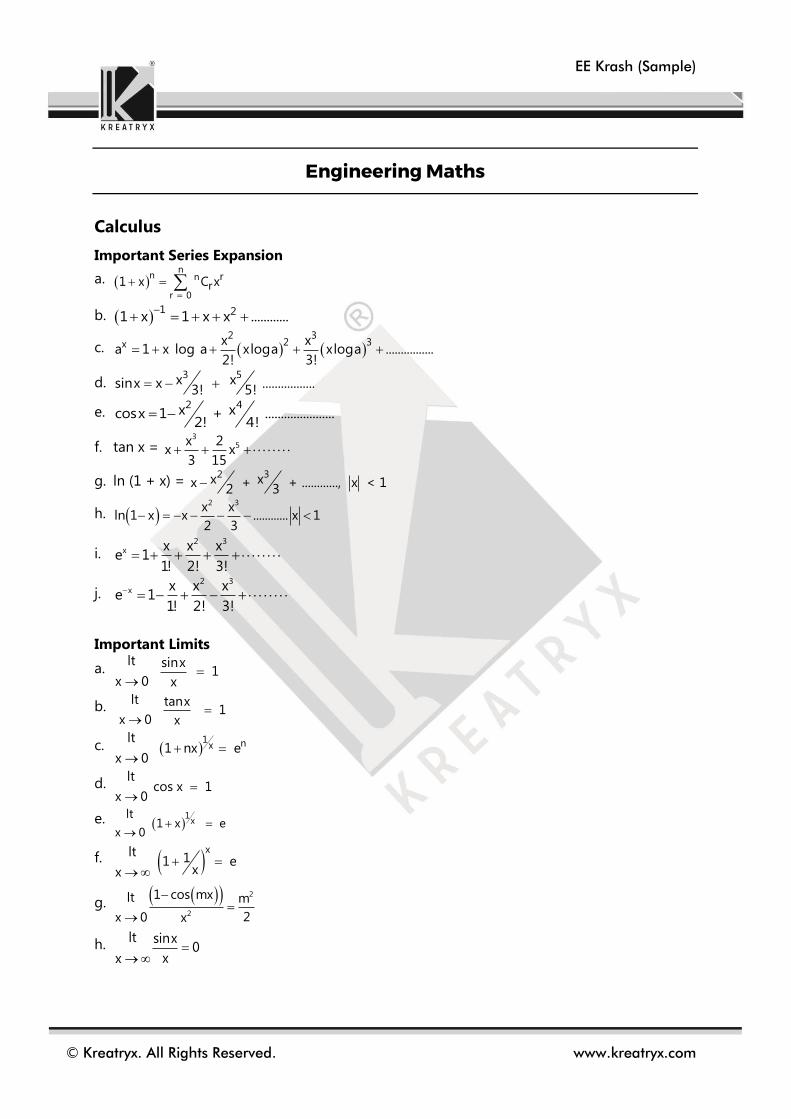
Important Series Expansion
a.
b.
c.
d.
e.
f. tan x =
g. ln (1 + x) =
h.
i.
j.
Important Limits
a.
b.
c.
d.
e.
f.
g.
h.
n
n n
r 0
rr1 x C x
1 21 x 1 x x ............
2 3
2 3x x xa 1 x log a xloga xloga ................
2! 3!
3 5x xsinx x .................3! 5!
2 4x xcosx 1 + ......................
2! 4!3
5x 2x x
3 15
2 3x xx + + ............, x < 12 3
2 3x x
ln 1 x x ............ x 12 3
2 3x x x x
e 11! 2! 3!
2 3x x x x
e 11! 2! 3!
lt sinx 1
x 0 x
lt tanx 1
x 0 x
1 nx
lt 1 nx e
x 0
lt cos x 1
x 0
1
xlt
1 x ex 0
xlt 1 1 exx
2
2
1 cos mxlt m
2x 0 x
lt sinx0
xx

EE Krash (Sample)
© Kreatryx. All Rights Reserved. www.kreatryx.com
L – Hospital’s Rule
If f (x) and g(x) are two functions such that
and
Then,
If f’(x) and g’(x) are also zero as , then we can take successive derivatives till this
condition is violated.
For continuity,
For differentiability, exists and is equal to
If a function is differentiable at some point then it is continuous at that point but converse
may not be true.
Mean Value Theorems
Rolle’s Theorem
If there is a function f(x) such that f(x) is continuous in closed interval a ≤ x ≤ b and f’(x) is
existing at every point in open interval a < x < b and f(a) = f(b). Then, there exists a point
‘c’ such that f’(c) = 0 and a < c < b.
Lagrange’s Mean value Theorem
If there is a function f(x) such that, f(x) is continuous in closed interval a ≤ x ≤ b; and f(x)
is differentiable in open interval (a, b) i.e., a < x < b,
Then there exists a point ‘c’, such that
Differentiation
Properties: (f + g)’ = f’ + g’ ; (f – g)’ = f’ – g’ ; (f g)’ = f’ g + f g’
Important derivatives
a. → n
b.
c.
d.
e.
f. sin x → cos x
g. cos x → –sin x
h. tan x →
lt
f x 0x a
lt
g x 0x a
lt ltf x f' x
x a x ag x g' x
x a
lim
f x =f ax a
00f x h f xlim
h 0 h
0f ' x
f b f af ' c
b a
nx n 1x
1nxx
a a1log x (log e)
x
x xe ex x
ea a log a
2sec x
EE Krash (Sample)
© Kreatryx. All Rights Reserved. www.kreatryx.com
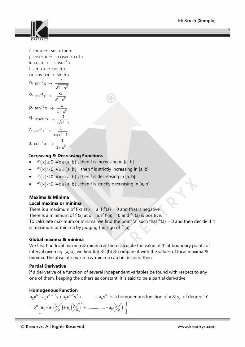
i. sec x → sec x tan x
j. cosec x → – cosec x cot x
k. cot x → – cosec2 x
l. sin h x → cos h x
m. cos h x → sin h x
n.
o.
p.
q.
r.
s.
Increasing & Decreasing Functions
, then f is increasing in [a, b]
, then f is strictly increasing in [a, b]
, then f is decreasing in [a, b]
, then f is strictly decreasing in [a, b]
Maxima & Minima
Local maxima or minima
There is a maximum of f(x) at x = a if f’(a) = 0 and f”(a) is negative.
There is a minimum of f (x) at x = a, if f’(a) = 0 and f” (a) is positive.
To calculate maximum or minima, we find the point ‘a’ such that f’(a) = 0 and then decide if it
is maximum or minima by judging the sign of f”(a).
Global maxima & minima
We first find local maxima & minima & then calculate the value of ‘f’ at boundary points of
interval given eg. [a, b], we find f(a) & f(b) & compare it with the values of local maxima &
minima. The absolute maxima & minima can be decided then.
Partial Derivative
If a derivative of a function of several independent variables be found with respect to any
one of them, keeping the others as constant, it is said to be a partial derivative.
Homogenous Function
is a homogenous function of x & y, of degree ‘n’
=
1
2
1sin x
1 - x
2
1 -1cos x
1 x
2
1 1tan x
1 x
2
1 -1cosec x
x x 1
2
1 1sec x
x x 1
12
-1cot x
1 x
f ' x 0 V x a, b
f ' x 0 V x a, b
f ' x 0 V x a, b
f ' x 0 V x a, b
n 2 2n n 1 nn0 1 2
a x a x y a x y ............. a y
2 n
n0 1 2n y y y
x a a a .................... ax x x

EE Krash (Sample)
© Kreatryx. All Rights Reserved. www.kreatryx.com
Euler’s Theorem
If u is a homogenous function of x & y of degree n, then
Maxima & minima of multi-variable function
; ;
Maxima
rt – s2 >0 ; r < 0
Minima
rt – s2>0 ; r > 0
Saddle point
rt – s2< 0
Integration
Indefinite integrals are just opposite of derivatives and hence important derivatives must
always be remembered.
Some standard integral formula
u ux y nu
x y
2
2
x a
y b
flet r
x
2
x a
y b
fs
x y
2
2
x a
y b
ft
y
n 1n x
x dx cn 1
xxa loga dx a c
xxe dx a c
uv dx u v u v c
sinx dx cosx c cosx dx sinx c
tanx dx ln secx c cosecx dx ln cosecx cotx c
secx dx ln secx tanx c cotx dx ln sinx c
1
2
1 dx sin x c
1 x
1
2
1 dx cos x c
1 x
1
2
1dx tan x c
1 x
1
2
1dx cot x c
1 x

EE Krash (Sample)
© Kreatryx. All Rights Reserved. www.kreatryx.com
Properties of definite integral
a.
b.
c.
d.
e.
f.
g.
1
2
1dx cosec x c
x x 1
1
2
1dx sec x c
x x 1
1
2 2
1 xdx sin c
aa x
1
2 2
1 1 xdx tan c
a aa x
2 2
1 1 x adx ln c
2a x aa x
2 2
1 1 x adx ln c
2a x ax a
2 2
2 2
1dx ln x x a c
x a
2 2
2 2
1dx ln x x a c
x a
b b
a a
f x dx f t dt
b a
a b
f x dx f x dx
b c b
a a c
f x dx f x dx f x dx
b b
a a
f x dx f a b x dx
a
2a
0
0
2 f(x)dx if f(2a-x)=f(x)f(x)dx
0 if f(2a-x) f(x)
a
a
0
a
2 f(x)dx if f(x)=f(-x)f(x)dx
0 if f(x) f(x)
t
t
df x dx f t ' t f t ' t
dt

EE Krash (Sample)
© Kreatryx. All Rights Reserved. www.kreatryx.com
Analog Electronics
BJT Amplifier & MOSFET Amplifier
Early effect or Base – width Modulation
Mode JE JC Property Application
1 Cut off RB RB Very high internal
resistance
OFF Switch
2 Saturation FB FB Very low internal
resistance
ON Switch
3 Forward
Active
FB FB Excellent transistor
action
Amplifier
4 Reverse
active
RB FB Poor transistor action Attenuator, logic
circuits
B Base width
W Width of depletion region of Base – collector junction.
VPB Potential barrier due to depletion region.
As VCB [reserve bias voltage] varies, width of depletion region [w] varies, hence width of base
[B] varies. This is known as early effect or base width Modulation
Due to early effect,
IB : AS VCB , W , B . Therefore, time for which electron remains in base decreases. This
decreases recombination in base. Hence IB decreases.
IC : Since number of electrons recombining in base decreases, number of electrons
reaching to collector increases. Hence IC .
IE : AS VCB , W , VPB across JBC, number of e-denting from B to C , no. of e- in B ,
Concentration gradient across JBE, deficiency of e- in Emitter , e-Supply by negative
terminal of VFB IE .

EE Krash (Sample)
© Kreatryx. All Rights Reserved. www.kreatryx.com
Current equations for different configurations.
For common Base configuration
IC = IE + ICBO [ICBO = ICO]
For common Emitter configuration
IC = IB + ICEO
For common Collector configuration
IE = IB + [I + ] ICBO
= 1
, =
1
1 = 1 +
ICFO = (1 + ) ICBO = (1 + ) ICO
Where:
Common base forward current gain
Common Emitter forward current gain
Common Collector forward current gain
ICBO Conventional leakage current from collector to base with emitter open.
[Common base configuration]
ICEO Conventional leakage current from collector to emitter with base open.
[Common emitter configuration]

EE Krash (Sample)
© Kreatryx. All Rights Reserved. www.kreatryx.com
Comparison of Different BJT Configuration.
Parameters CB
CE CC
Circuit
diagram
Common
terminal
Base is common to
input & output for
AC
Emitter is common to
input & output for AC
Collector is common to
input & output for AC
AC input
resistance
low, 20 to 100 Moderate, 1k to 3k high, in mega ohm‘s
AC output
resistance
High, 1 to 3 M Moderate, 40 to 80k very low in ohm‘s
Current
gain
, Very low, < 1 , moderate, 20 to 300 , large, = 1 +
Voltage
gain
> 1, but power gain
is low
>1, power gain is high 1, unity gain
Phase Input & output in
Phase
input & output out of
phase
input & output in phase
Impedance
matching
Cascading is not
efficient
efficient cascading is
possible with common
collector
works as impedance
matching amplifier
Leakage
current
very small
[ICBO] 5µA for Ge
[ICBO]1µA for Si
very large [ICEO]
500 µA for Ge
20 µA for Si
same as that of CE [ICFO]
Applications Constant current
source, high band
width amplifier
Voltage amplifier Buffer or Impedance
matching amplifier
Selection of Q Point [VCFQ, ICQ]
While designing CE amplifier, values of different resistors & voltages [DC] must be selected in
such a way that,
Q point should be in active region
Q point should be on DC load line
As for as possible, Q point should be selected in middle of load line to avoid clipping of
signal.
The Q Point Shifts on DC load line, because of following reason
Variation in device parameter.

EE Krash (Sample)
© Kreatryx. All Rights Reserved. www.kreatryx.com
Thermal instability Temperature variation.
(a) Decrease in VBE with increase in temperature.
(b) Increase in β with increase in temperature.
(c) Change in ICO with temperature.
Stability factor [s] = C
CO
I
I
=
B
C
1+β
I1-β
I
Stability factor is Parameter with decides to what extent a biasing method is successful to
keep Q point stable.
1. Fixed bias 1. Use of diode for VBE compensation
2. Fixed bias with self-bias or Emitter f/b bias 2. Use of diode for ICO compensation
3. Collector to base bias 3. Use of thermistor
4. Potential divider biasing with for compensation emitter bias or self-bias
Type of biasing Fixed bias Fixed bias with
self-bias or
Emitter f/b bias
Collector to
base bias
Potential divider
biasing with
emitter bias or self-
bias
Circuit diagram
Stability factor
[S]
S = 1 + S =
E
B E
1
R1
R R
S =
S = E
E B
1
R1
R R
C
C B
1
R1
R R

EE Krash (Sample)
© Kreatryx. All Rights Reserved. www.kreatryx.com
Different models of BJT
re model for common base configuration. [PNP]
0r Common base output resistance
re =
re model for common base configuration [NPN]
0r Common base output resistance
re model for common Emitter configuration [NPN]
0r Common emitter output resistance
High frequency model – Hybrid model or Via collector model [ECE only]
EQ
26 m
I

EE Krash (Sample)
© Kreatryx. All Rights Reserved. www.kreatryx.com
Relation between different Parameters.
(1) hie = r = re (2) gm = e
r
e
1
r
(3) ro = oe
1
h (4) = hfe
AC Equivalent Circuit of MOSFET [ECE Only]
Model:
ro = DQ
1
I = A
DQ
V
I
VA early voltage
IDQ DC drain current
Common Source Amplifier with current minor bias.
m1 0 ng 2I K

EE Krash (Sample)
© Kreatryx. All Rights Reserved. www.kreatryx.com
Common Drain Amplifier or Source Follower Amplifier.
AV = O
S
V
V =
If we choose gm RL >> 1, then AV 1, then Av 1
If rds. [drain–source resistance/ output resistance] considered, then
o
s
v
v =
Ri = R1 II R2 ; Ro = ; gds =
Common Source Amplifier with Source Degeneration
o
s
v
v = M O L
M X
I [R / R ]
1+I R
Ri = R1IIR2
Rout = rds + gm rds Rx + Rx
m L
m L
g R
g R +1
m L ds
m L ds
g R r
1+g R r
m ds
1
g +g ds
1
r

EE Krash (Sample)
© Kreatryx. All Rights Reserved. www.kreatryx.com
Common Gate Amplifier.
o
s
v
v =
Rout = gm Rs rds + rds + RS
D L
S
R R
R
i
m
1R
g

EE Krash (Sample)
© Kreatryx. All Rights Reserved. www.kreatryx.com
Engineering Mechanics
Impulse, Momentum and Collisions
The impulse of a constant force F is defined as the product of the force and the time t for
which it acts.
Impulse = F.t
The effect of the impulse on a body can be found using below equations, where a is
acceleration, u and v are initial and final velocities respectively and t is time.
v u at v u at
So
chaI F ngt m e a t m in momentumv u
So we can say that,
Impulse of a constant force = F.t = change in momentum produced.
Impulse is a vector quantity and has the same units as momentum, Ns or kg m/s
The impulse of a variable force can be defined by the integral
Impulse=t
0
F.dt , where t is the time for which F acts.
By Newton's 2nd law
F m.a m dv / dt
So impulse can also be written
Impulsev v
v
uu u
dvm dt mdv mv
dt
which for a constant mass
Impulse =m (v-u)
Impulsive force
Suppose the force F is very large and acts for a very short time. During this time the
distance moved is very small and under normal analysis would be ignored. Under these
conditions, the only effect of the force can be measured is the impulse, or change in
momentum which is called an impulsive force.
In theory this force should be infinitely large and the time of action infinitely small. Some
applications where the conditions are approached are collision of snooker balls, a
hammer hitting a nail or the impact of a bullet on a target.
Conservation of linear momentum
Consider the direct collision of two spheres A and B.

EE Krash (Sample)
© Kreatryx. All Rights Reserved. www.kreatryx.com
When the spheres collide, then by Newton's third law, the force F exerted by A on B is
equal and opposite to the force exerted by B on A.
The time for contact is the same for both. The impulse of A on B is thus equal and
opposite to the impulse of B on A. It then follows that the change in momentum of A is
equal in magnitude to the change in momentum in B, but it is in the opposite direction.
The total change in momentum of the whole system is thus zero.
This means that the total momentum before and after a collision is equal, or that linear
momentum is conserved. This is called the principle of conservation of linear momentum
and in summary this may be stated:
The total momentum of a system, in any direction, remains constant unless an external
force acts on the system in that direction.
Caution: Take proper sign convention while solving problems.
Impact of inelastic bodies
When two inelastic bodies collide they remain together. They show no inclination to
return to their original shape after the collision.
An example of this may be two railway carriages that collide and become coupled on
impact.
Problems of this type may be solved by the principle of conservation of linear
momentum.
Momentum before impact = Momentum after impact
(Take proper sign convention)
Although momentum is conserved, it is important to realize that energy is always lost in
an inelastic collision (it is converted from mechanical energy to some other form such as
heat, light or sound.)
Impact of elastic bodies
In the last section the bodies were assumed to stay together after impact. An elastic body
is one which tends to return to its original shape after impact. When two elastic bodies
collide, they rebound after collision. An example is the collision of two snooker balls.
If the bodies are travelling along the same straight line before impact, then the collision is
called a direct collision. This is the only type of collision considered here.
Consider the two elastic spheres as shown. By the principle of conservation of linear
momentum
Momentum before impact = Momentum after impact
1 1 2 2 1 1 2 2m u m u m v m v
where the i
u initial velocity of body i.
i
v final velocity of body i.

EE Krash (Sample)
© Kreatryx. All Rights Reserved. www.kreatryx.com
When the spheres are inelastic v1 and v2 are equal as we saw in the last section. For elastic
bodies v1 and v2 depend on the elastic properties of the bodies. A measure of the
elasticity is the coefficient of restitution, for direct collision this is defined as
1 2
1 2
v ve
u u
The values of ‘e’ in practice vary between 0 and 1. For completely inelastic collision, e 0
and for completely elastic collision, e=1. In the latter case, no energy is lost in the
collision.
Both the law of restitution & conservation of momentum are applicable along x and y
directions in case of oblique collision.
Rolling, torque and angular momentum
Rolling motion:
Combination of translational motion & rotational motion.
In rolling motion, the centre of the object moves in a line parallel to the surface.
Relation between length and angle of rotation:
When the object rotates through an angle ' ' , a point at a distance R from the rotation axis
moves through a distance of S
S R
The arc length S is the same as the distance that the wheel translates.
The linear (translational) speed COM
V of the wheel is dS
dt;
COMV is the velocity of centre of mass.
The angular speed of the wheel is d
dt
So, dS d
Rdt dt
COMV R
Rolling motion is the combination of pure rotational motion and pure translational motion.

EE Krash (Sample)
© Kreatryx. All Rights Reserved. www.kreatryx.com
Pure rotation + pure translation = Rolling motion
The velocity of a point at the top of the rolling wheel is twice that of the centre of the wheel
top COMV 2R 2 R 2V
Kinetic energy of rolling:
As an object rolls, the point at the very bottom, the contact point with the surface, is
instantaneously stationary.
We will call this point P and we can treat rolling about this point.
K.E= 2
P
1I
2
PI : Rotational inertia about the point P
Parallel axis theorem says 2
P COMI I MR
2
P
1K.E I
2
2 2 2
COM
1 1K.E I MR
2 2
2 2
COM COM
1 1K.E I MV
2 2
Kinetic energy of a rolling object comes from rotational kinetic energy and translational
kinetic energy.
Forces in rolling:
If a wheel rolls smoothly, there is no sliding at the contact point so there is no friction.
However if there is an external force that produces an acceleration, there will be an
angular acceleration . The acceleration will make the wheel want to slide at the contact
point. Then a frictional force will be on the wheel to oppose the tendency to slide.
Direction of static frictional force:
If a wheel moving to the right were to accelerate, the bottom of the wheel would want to
move to the left compared to the surface. Thus static friction force is to the right.
If same wheel was to slow down, the direction of the acceleration and angular acceleration
would switch and the static friction force will now be pointing towards the left.

EE Krash (Sample)
© Kreatryx. All Rights Reserved. www.kreatryx.com
Rolling down a ramp:
The direction of the static friction force is the confusing part here. It points up along the
ramp. If the wheel were to slide down the ramp, the friction opposing the sliding would be
pointing up.
s COMf Mgsin Ma
I
Only force on the wheel that produces torque is the friction
s COMRf I
We will need to make use of COM
a R
(a is down the ramp, negative X-direction but the wheel rolls counter-clockwise, is positive)
COMa
R
So we can solve for COM
s COM 2
af I
R
COM
COM
2
gsina
I1
MR
Yo-Yo
A Yo-Yo behaves similar to the wheel rolling down a ramp.
1) Instead of rolling down a ramp of angle ' ' , Yo-Yo follows an angle of 090 with horizontal.
2) Yo-Yo rolls down a string on a radius R.
3) Instead of friction, the tension shows up in the Yo-Yo.
COM
COM
2
0
ga
I1
MR

EE Krash (Sample)
© Kreatryx. All Rights Reserved. www.kreatryx.com
Electrical Machines
Transformer
MMF and Flux
C
C
C C
C
C
C
Ni
A l
lNi
A
F R
c
c
lR
A
Reluctance of transformer core
Flux in core
F=MMF
cl = Effective length of Core
cA = Cross-Sectional Area of the core
= permeability of the core
Construction
In a Transformer the primary and secondary windings are wound around the core of a
transformer. Core is a magnetic material which allows the flow of magnetic flux lines to link
both primary and secondary windings. Also it provides mechanical support to the
Transformer.
1. Core should have low reluctance and high permeability to the flow of magnetic flux.
2. Core is generally made of Silicon steel
3. Generally, this steel is cold rolled grain oriented CRGO steel, to increase permeability
along the direction of magnetization and reduce core losses.
4. KVA Rating (Core Dimension)4 5. Voltage Rating (Core Dimension)2
6. Current Rating (Core Dimension)2
7. No-Load Current Core Dimension
8. Core Loss Core Volume
Properties of Ideal Transformer
Permeability of transformer is infinite.
No Iron or Copper Loss.

EE Krash (Sample)
© Kreatryx. All Rights Reserved. www.kreatryx.com
Induced EMF in a Transformer
For a practical transformer with finite permeability the induced emf can be calculated as,
The instantaneous values of induced emf in primary and secondary are given by,
1 1
2 2
de N
dt
de N
dt
The rms values of induced emf is given as,
1 1 m
2 2 m
E (rms) 4.44fN
E (rms) 4.44fN
Where E1 and E2 are emf in primary and secondary windings of Transformer respectively.
Φ is the flux in the transformer and Φm is maximum value of flux.
m m n
B A where Bm is the maximum value of magnetic flux density and An is the cross
sectional area of the core.
The polarity of emf is decided on basis of Lenz Law as currents in primary and secondary
should be such that primary and secondary flux should oppose each other.
Also, primary current enters the positive terminal of primary winding as primary absorbs
power and secondary current leaves the positive terminal of secondary winding as
secondary delivers power and this way we can mark emf polarities.
Induced EMF always lags the emf by 900.
If the frequency of operation of a transformer is reduced then KVA rating of transformer
reduces proportionately as induced emf varies linearly with frequency.
For a given KVA rating and for given maximum value of B of core, more the designed
frequency lesser is size and weight of transformers.
Exact equivalent circuit
'
1 0 1I I I
Exact equivalent circuit with respect to primary

EE Krash (Sample)
© Kreatryx. All Rights Reserved. www.kreatryx.com
2 2 2
1 1 1
2 2 2 2 L L
2 2 2
N N NR = R ; X = X ; Z = Z
N N N
;
Approximate Equivalent Circuit
01 1 2R = R R
01 1 2X = X X
In this approximation, we are neglecting the no-load copper losses and we are
overestimating the core losses.
The phasor diagram for the exact equivalent circuit is shown below,
I: Magnetizing Current
wI : Core-loss Component of No-Load Current
0I : No-Load Current
o70 to 75
0cos 0.2lag (No-Load pf)
Here, o is the angle between E1 and I0
Transformer has poor No load PF because w
I I
1 1 2 2N I ' N I
Load component of primary MMF = Secondary MMF
2 1 2
1 2 1
N I ' EK
N I E = Transformation ratio

EE Krash (Sample)
© Kreatryx. All Rights Reserved. www.kreatryx.com
Synchronous Machine
Synchronous Speed
e m
P
2
If we differentiate both sides,
e m
e
m
m
P
2
2 f
P2 f
2
4 frad / s
P
4 f2 N ; N rev / s
P
2fN rev / s
P
2fN 60rev / min
P
s
120fN rpm
P
Induced emf
Phase voltage ph
4.44 N f
phN : number of turns per phase
: flux per pole
f : frequency
This phase voltage is rms value & it is valid for a full pitched concentrated winding only.
Armature Winding
Usually, coil span is 180 (electrical)
If coil span = 180 (electrical), coil is called as full pitch coil.
If coil span = 180 (electrical), coil is called as Chorded coil or short pitched winding.
Pitch Factor,
PK = cos
2
Induced emf ph P 4.44 N f K ……….for short-pitched concentrated winding only
For thn harmonic
Induced emf ph P 4.44 N f K
P
nK = cos
2
To eliminate thn harmonic
n =
2 2
180
= electricaln
EE Krash (Sample)
© Kreatryx. All Rights Reserved. www.kreatryx.com
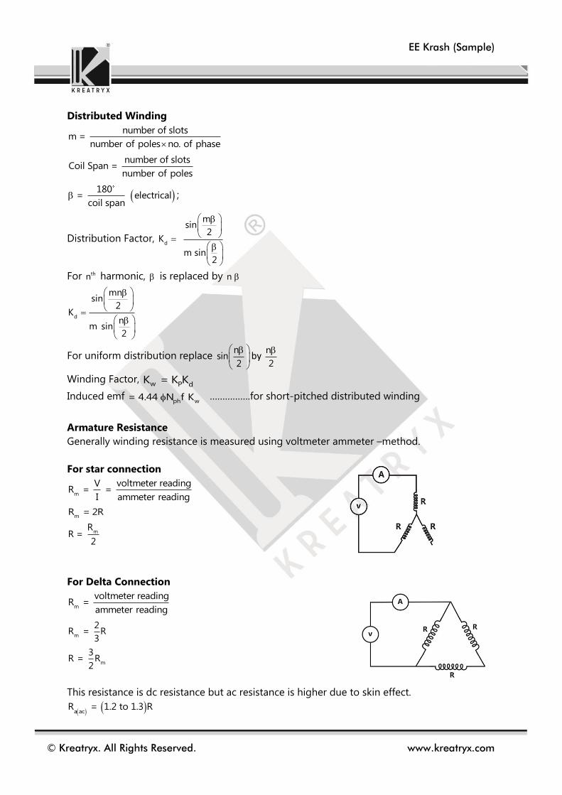
Distributed Winding
number of slotsm =
number of poles no. of phase
number of slotsCoil Span =
number of poles
180
= electricalcoil span
;
Distribution Factor, d
msin
2K
m sin2
For thn harmonic, is replaced by n
d
mnsin
2K
nm sin
2
For uniform distribution replace n
sin2
by n
2
Winding Factor, w P d
K = K K
Induced emf ph w
= 4.44 N f K …………….for short-pitched distributed winding
Armature Resistance
Generally winding resistance is measured using voltmeter ammeter –method.
For star connection
m
voltmeter readingVR = =
I ammeter reading
mR = 2R
mR
R = 2
For Delta Connection
m
voltmeter readingR =
ammeter reading
m
2R = R
3
m
3R = R
2
This resistance is dc resistance but ac resistance is higher due to skin effect.
a acR = 1.2 to 1.3 R

EE Krash (Sample)
© Kreatryx. All Rights Reserved. www.kreatryx.com
Armature Reaction
Power factor Generator Motor
Unity
Zero pf lagging
Zero pf leading
Lagging pf cos
Leading pf cos

EE Krash (Sample)
© Kreatryx. All Rights Reserved. www.kreatryx.com
Leakage Flux
Leakage flux links only one winding but not both so if it is present in stator, it won’t link to
rotor & vice-versa (the function of leakage flux is just same as that of choke in a coil; to drop
voltage)
Equivalent Circuit
sX = synchronous reactance
ar l X X = sum of armature reaction reactance & leakage
reactance
a a sE V 0 + I (R jX ) , for Synchronous Generator
a a sE V 0 - I (R jX ) , for Synchronous Motor
( and are positive)
Where Φ is power factor angle (leading)
for lagging power factor we replace Φ by “– Φ”
Voltage Regulation
Voltage regulation E V
100%V
2 2
a a a s
2 2
a a a s
E (Vcos I R ) (Vsin I X ) for lagging pf load
E (Vcos I R ) (Vsin I X ) for leading pf load
Zero Voltage Regulation is only possible for leading pf loads.
For zero regulation 2 2E V 0
a sI Z
cos( )2V
Negative sign because ( )>90
For maximum voltage regulation
=
cos = load pf lagging

EE Krash (Sample)
© Kreatryx. All Rights Reserved. www.kreatryx.com
Power Electronics
Chopper
Buck Converter
When CH is ON o t DT
Voltage across inductor L S OV V V
When CH is OFF (DT < t < T)
Voltage across inductor L 0
V V
Applying volt-sec balance across inductor
S O OV V DT V T DT 0
S O OV V D V 1 D 0
O SV DV
D = duty cycle = ON
T
T
Where T = switching period = 1f
f = switching frequency
Average output voltage = S
DV
rms output voltage = S
DV
Average source current = O
DI
Average current of FD = O1 D I
Ripple in output current
When CH is ON 0 t DT
L S O SV V V 1 D V
During this period, since voltage is positive current
increase from minimum value to maximum value.
max mini I I
t DT 0 DT
S
iL 1 D V
DT
SD 1 D V
ifL

EE Krash (Sample)
© Kreatryx. All Rights Reserved. www.kreatryx.com
The formula below approximate value of output ripple current for maximum ripple, D = 0.5
S
max
Vi
4fL
L
max O
II I
2
L
min O
II I
2
Critical Inductance (LC)
Value of inductance at which inductor voltage waveform is just discontinuous.
c
1 D RL
2f
Critical Capacitance (CC)
Value of capacitance at which current through inductor is just discontinuous.
C
1C
8fR
Step-up chopper (Boost converter)
L Swhen CH is ON 0 t DT , V V
L S Owhen CH is OFF DT t T , V V V
Applying volt-sec balance across inductor
S S OV DT V V 1 D T 0
S
O
VV
1 D
Since D < 1, O S
V V
C Owhen CH is ON 0 t DT , I I
C L Owhen CH is OFF DT t T , I I I
O L O
Applying Ampere sec balance across capacitor
I DT I I 1 D T 0
OL
II
1 D

EE Krash (Sample)
© Kreatryx. All Rights Reserved. www.kreatryx.com
Ripple in inductor current
min max
When CH is ON 0 t DT ,
current increase from I to I
S SL
S L
V DT DViL V i
DT L fL
Ripple in output voltage
C Owhen CHis ON , I I
C
O
VC. I
DT
O
O C
I DTV V
C
-ve sign indicates voltage decrease
O
O
I DTV
C
Critical Inductance (Lc)
L
L
II
2
C
D 1 D RL
2f
Critical Capacitance (Cc)
O
O
VV
2
C
DC
2fR
If inductor also has an internal resistance, then
O S 2
1 DV V
r 1 DR
r = internal resistance of inductor; R = load resistance

EE Krash (Sample)
© Kreatryx. All Rights Reserved. www.kreatryx.com
Control Systems
Transient Analysis
For Concept, refer to Control Systems K-Notes, Time Response Analysis
For the system shown in figure, with a damping ratio of .7 and an un-damped natural
frequency of 4 rad/sec, the values of ‘K’ and ‘a’ are
(A)K=4,a=.35
(B)K=8,a=.455
(C)K=16,a=.225
(D)K=64,a=.9
Solution: (C) is correct option
Characteristic equation
01. A controller of the form is designed for a plant with transfer function
such that the un-damped natural frequency and the damping ratio of the closed
loop 2nd order system are 2 rad/sec and 0.5 respectively. When the steady state error to a
unit step input is zero, then the controller parameters are
(A) k = 4, a = 3, b = 2 (B) k = 1, a = 3, b = 2
(C) k = 4, a = 2, b = 3 (D) k = 1, a = 2, b = 3
0
1 G(s)H(s) 0
K(1 as)1 0
(s 2)2
2
S 2s Kas K 0
S s(Ka 2) K 0
Compare with standard equation
2 2n n
2 2n
S 2 s 0
K 4 16 => K 16
nKa 2 2 2(.7)(4)
2(.7)(4) 2a .225
16
c
K(s a)G (s)
(s b)
1G(s)
s(s 3)
Problems
Sample Problem
Kuestion

EE Krash (Sample)
© Kreatryx. All Rights Reserved. www.kreatryx.com
01. Ans: (A)
Solution:
So overall OLTF=
As it is a second order system. So taking a=3
(a=b not in the option, so not taken & s=3 cannot be an open loop pole also)
Now un-damped natural frequency
Damping factor=
Now second order OLTF=
So K=4, b=2, a=3
02. A feedback system has un-damped frequency of 10 rad/sec and the damping ratio is 0.4
the transfer function is?
(A) (B)
(C) (D)
02. Ans: (A)
Solution:
Given
(Standard form)
TF=
03. A system is required to have a peak overshoot of 4.32 % and a natural frequency of 5
rad/sec. The required location of the dominant pole is:
(A) – 3.535 + j 5.535 (B) – 2.535 + j 2.525
(C) – 2.535 + j 3.535 (D) – 3.535 + j 3.535
03. Ans: (D)
Solution:
,
=(Delivered from the formula)
C
K s a 1G s and G s
s b s s 3
K s a
s s b s 3
A
2
0.5
2
A
A
4
s s 2 s s 2 0.5 2 4
S S 2
2
100
(s 8s 100) 2
10
(s 8s 10)
2
100
(s 4s 100) 2
10
(s 8s 100)
n10 rad / sec 0.4
2
n
2 2
n n
TFs 2 s
2
100
s 0.8 10s 100
2
100
s 8s 100
P%M 4.32% 0.0432
n5rad / sec
2
p
22
p
ln M
ln M
21tan
P%M e e

EE Krash (Sample)
© Kreatryx. All Rights Reserved. www.kreatryx.com
So pole location=
04. Match List – I (Location of roots) with List – II (Step response) and select the correct
answer using the codes given below the lists:
P Q R S
(A) 4 1 2 3
(B) 5 1 2 3
(C) 4 2 1 3
(D) 5 2 3 4
0.707
2
n nj 1 3.535 j3.535

EE Krash (Sample)
© Kreatryx. All Rights Reserved. www.kreatryx.com
04. Ans: (B)
Solution:
(P) So CE=
One pole system
(Q) Left hand poles & conjugate poles
Poles under damped system
(R) Marginally stable system
(S) Right hand poles
Unstable system
05. The open loop transfer function of a system is for a unit step input to
the system, the approximate settling time for 2% criterion is
(A) 100 sec (B) 4 sec
(C) 1 sec (D) none
05. Ans: (D)
Solution:
OLTF= so CLTF=
So CE=1+OLTF=(S+1)(S+100)=
Comparing with
We get
For 2% criterion, not in the answer
S 0
100G(s)
(s 1)(s 100)
100
S 1 S 100
OLTF
1 OLTF
2s 101s 2002 2
n nS 2
n101 50.5
2
n
4 4
50.5

EE Krash (Sample)
© Kreatryx. All Rights Reserved. www.kreatryx.com
06. Consider the R-L-C circuit shown in figure, For a step-input ei, the overshoot in the
output eo will be
(A) 0
(B) 5 %
(C) 16 %
(D) 48 %
06. Ans: (C)
Solution:
Here [Converting to standard from]
For RLC circuit
Now peak overshoot= =0.1630=16.3%
07. Consider the block diagram of the control system shown in the figure below. The peak
overshoot of the system is 9.49%. The value of the constant k and the steady state error for a
unit ramp input are
(A) 0.18 and 0.20 (B) 0.36 and 0.36
(C) 0.52 and 0.18 (D) 0.52 and 2.14
07. Ans: (A)
Solution:
1 sk 10G s
s s 2
For unity negative feedback system
2
10 10skT s
s s 2 10k 10
Compare with standard second order transfer function
n10 3.16rad sec
0
i
1R sCTF
1RR sL
sC
2
1
LCR 1
s sL LC
6
3
R C 10 10 10 15 0.5
2 L 2 101 10
8 4
n3 6
1 110 10
LC 10 10 10
21e

EE Krash (Sample)
© Kreatryx. All Rights Reserved. www.kreatryx.com
n2 2 10k
n2 2
k10
Now, 21
PM % 9.49% e
0.6
Thus, k 0.18
For Type one system
Velocity error constant
V s 0
10k limsG s 5
2
ss
V
1e 0.2
k
08. The pole location of one of the two closed loop poles of a second order control system
with unity negative feedback is shown below. The value of peak overshoot PM is ____________
%.
08. Ans: 13.53
Solution:
The standard transfer function of second order system
2
n
2 2
n n
C s
R s s 2
2
n ns 1
Here, n
2
2
n1
2
2
1
21
P%M e 100%
2
e 100%
2e 100% 13.53%
09. The block diagram of a unity feedback control system is shown:

EE Krash (Sample)
© Kreatryx. All Rights Reserved. www.kreatryx.com
The time period of oscillation before reaching the steady state is
(A) 0.6 sec (B) 0.78 sec
(C) 1.56 sec (D) 1.84 sec
09. Ans: (C)
Solution:
20G s
s 1 s 5
For unity negative feedback system
2
G s 20T s
1 G s s 6s 25
Compare it with general second order system 2
1 n2 2
n n
kT s k k
s 2 s
By comparison, 2
n n25 5rad / sec
n
32 6 0.6.
5
2
d n
91 5 1 4 rad / sec.
25
Time period of oscillationd
2.
2 1.56 sec
4 2

EE Krash (Sample)
© Kreatryx. All Rights Reserved. www.kreatryx.com
Bode Plot
For Concept refer to Control System K-Notes, Bode Plots
The asymptotic approximation of the log-magnitude v/s frequency plot of a system containing only real poles and
zeros is shown. Its transfer function is
(A)
(B)
(C)
(D)
Solution: (B) is correct option
Since initial slope of the bode plot is −40 dB/decade, so no. of poles at origin is 2.
Transfer function can be written in following steps:
Slope changes from −40 dB/dec. to −60 dB/dec. at ω1 = 2 rad/sec., so at ω1 there is a pole in the transfer
function.
Slope changes from −60 dB/dec to −40 dB/dec at ω2 = 5 rad/sec., so at this frequency there is a zero lying in
the system function.
The slope changes from −40 dB/dec to −60 dB/dec at ω3 = 25 rad/sec, so there is a pole in the system at this
frequency.
01. The Bode plot of a system is given its transfer function is
(A)
(B)
10(s 5)
s(s 25)(s 2)
2
1000(s 5)
s (s 25)(s 2)
100(s 5)
s(s 25)(s 2)
2
80(s 5)
s (s 25)(s 2)
2
K(s 5)Transfer Function T(s)
s (s 25)(s 2)
at =.1
2
Constant term can be obained as : T(j ) 80
K(5)So, 80 20log => K 1000
(.1) 50
2
1000(s 5)Therefore the Transfer Function is T(s)
s (s 25)(s 2)
(1 0.1s)(1 0.01s)
(1 s)(1 0.001s)
(1 0.1s)(1 s)
(1 0.01s)(1 0.001s)
Problems
Sample Problem
Common Mistake / Point to remember
Remember the x-axis is always in terms of logω and not in terms of ω, this is a common mistake while
calculating slope.

EE Krash (Sample)
© Kreatryx. All Rights Reserved. www.kreatryx.com
(C)
(D)
02. What is the transfer function for given bode plot shown in the figure
(A)
(B)
(C)
(D)
03. The asymptotic Bode plot of the transfer function is given in figure. The error in phase angle
and dB gain at a frequency of ω = 0.5a are respectively
(A) 4.90, 0.97 dB (B) 5.70, 3 dB
(C) 4.90, 3 dB (D) 5.70, 0.97 dB
04. The asymptotic magnitude Bode plot of an open loop system G(s) with K>0 and all poles and zeroes on the s-
plane is shown in the figure. It is completely symmetric about ωc. The minimum absolute phase angle
contribution by G(s) is given by
(A) 78.60
(B) 900
(C) 101.40
(D) 1800
(1 10s)(1 s)
(1 0.1s)(1 0.001s)
(1 0.001s)(1 s)
s(1 10s)
2
3
4(s 0.5)
(s 10)
2
3
16000(s 0.5)
(s 10)
2
3
160(s 0.5)
(s 10)
2
3
1600(s 0.5)
(s 10)
KT(s)
s(1 )
a

EE Krash (Sample)
© Kreatryx. All Rights Reserved. www.kreatryx.com
05. The open loop transfer function of a system is given by in the straight–line
approximation of the Bode plot
(A) (B)
(C) (D)
06. For the bode plot shown in the below figure. The transfer function is __________________.
(A) 1 s
1 s
(B)
2
1
s 1
(C) 1
1 s (D)
2
1
s s 1
07. The asymptotic Bode magnitude plot for open loop transfer function of a unity negative feedback system is
shown in figure. If the input is 2t
u t2
, then the steady state error will be _________.
08. The Bode plot of a transfer function G(s) is shown
The gain 1020log G s
is 18dB and –2dB at 1rad/sec and 10rad/sec respectively. The value of gain at
ω=5rad/sec is _________ dB.
100(s 100)G(s)H(s)
s(s 10)
G(j )H(j ) and G(j ) at =100 rad/sec are
30 dB and rad
4
0 dB and rad
4
320 dB and rad
4
20 dB and rad
4

EE Krash (Sample)
© Kreatryx. All Rights Reserved. www.kreatryx.com
01. Ans: (A)
Solution:
Between 1 and ω1, the change in magnitude is 20dB and since slope is 20dB/dec so between 1 and ω1 there
should be a decade.
Similarly, 1000 and ω2 there should be a decade.
So should be a decade, so &
as there is a decade between 1 &
So s=1 pole
zero
zero
s=1000 pole
So
02. Ans: (B)
Solution:
At slop changes from 0dB to +40dB/dec
So s=0.5 = two zeros
At , slop +40dB -20dB
So s=10=three poles
At , Gain = 36dB
03. Ans: (A)
Solution:
Now at , gain =
So error=0.97dB in gain
2log1000 log
2100
110
1
1
s 10
2
s 100
s s1 1
1 0.1s 1 0.01s10 100TF
s 1 s 1 0.001s1 s 1
1000
0.5
10
2
3
K s 0.5TF
s 10
22
3
K 236 20log
10
k 16000
K KT s T j
s j1 1
a a
0.5a 2 220logK 20log 1 0.5
20logK 0.97dB

EE Krash (Sample)
© Kreatryx. All Rights Reserved. www.kreatryx.com
At , phase=
Now from the plot at
Let phase is
So
So error=31.45-26.56=4.90
04. Ans: (A)
Solution: At it is symmetrical about
So =10
The initial slope of bode plot is -40dB/decade which indicates there are two poles present at origin
The change of slope at 1 is 20dB/decade so there is a zero of order 1 and change of slope at 100 is -
20dB/decade so there is a pole of order 1
So
Now G(s) =
is a lag network
Here minimum phase angle
05. Ans: (A)
Solution:
Initial slope=-20dB/dec
Corner frequencies=100(zero), 10(pole)
Drawing the bode plot
At Gain=DC gain=
So
At , gain=
So 20log1=0 dB
0.5a 1 0tan 0.5 26.56
0.5a0x
00x
45log0.5a log0.1a
0 0x 45 log5 31.45
C
C
2
s 1TF
s s 100
s 1
s 100
1 s 1 100 0.01s 1 aTs0.01 K
1 Ts100 1 0.01s 1 0.01s
1 0a 1sin 78.6
a 1
100 s 100 100 100 1 0.01sG s H s
s s 10 10s 1 0.15
1000 1 0.01s
s 1 0.1s
1
1
G s H s 1000
20log1000 60dB
100
2
100
100 1001
s
1 1 1 3G j tan tan tan 10 2.2564100 10 2 4 2

EE Krash (Sample)
© Kreatryx. All Rights Reserved. www.kreatryx.com
06. Ans: (A)
Solution:
By observing magnitude plot gain = 0 dB
i.e. magnitude = 1
It is possible only in all pass filter.
Hence option (A) is correct
07. Ans: 10
Solution:
Here 1p 20dB,0.1 and 2 1
p 20dB,
2 1
2 1
y y40
x x
10 10 1
20 0
log 0.1 log
10 10 1
1log 0.1 log
2
10
1
1 11 log
2
10
1
1 1log
2
1
2
1
110
1
1
10
The initial slope of bode plot is -40dB/decade which indicates there are two poles present at origin
2 2
K 1G s
s 10s
At 1
1
10
2
1
K20log G s 20log 0dB
1K
10
Error for standard parabolic input ss
a
1e
K
2
a s 0
1K lims G s
10
ss
a
1e 10
K
08. Ans: 4.02
Solution:
Slope
18 220dB / dec
log1 log10
The transfer function is
The initial slope of bode plot is -20dB/decade which indicates there are one pole present at origin
K
G ss

EE Krash (Sample)
© Kreatryx. All Rights Reserved. www.kreatryx.com
K K
G sj
10 10 1020log G s 20log K 20log
At 1
1018 20log K
1820K 10
At 5
18
2010 10 10
20log G s 20log 10 20log 5 10
18 20log 5 4.02dB

EE Krash (Sample)
© Kreatryx. All Rights Reserved. www.kreatryx.com
Signal & Systems
Continuous Time Fourier Transform
For Concept refer to Signals and Systems K-Notes, Fourier Transform
Find the Fourier transform of the signal atx(t) te u(t) : a>0
(A) 1
a j (B)
a
a j
(C) 2(a j )
(D)
2
1
(a j )
Solution: (D) is correct option
j t j t (a j )tat at
0 0
X( ) te u(t)e dt te e dt te dt
(a j )t (a j )t
2
0 0
e eX( ) t
(a j ) (a j )
2 2
1 10
(a j ) (a j )X( )
The Fourier transform of the given signal x(t) is
(A) cos sin
4 j
(B) 2
cos sin2j
Sample Problem
Sample Problem
Common Mistake / Point to remember
Remember to consider the impulse function while taking the derivative of the rectangular function at the edges.

EE Krash (Sample)
© Kreatryx. All Rights Reserved. www.kreatryx.com
(C) 2
cos sin4 j
(D)
2
cos sin2j
Solution: (B) is correct option
Method 1
equation of x t t u t 1 u t 1 t 1 u t 1 u t 1 t 1 u t 1 u t 1
Taking Fourier Transfer j j j j
2 2 2
e e e e 1 2X( j ) [ 2jsin ] cos
j j j
2
cos sinX( j ) 2j
Method 2
equation of x t t u t 1 u t 1
Taking Fourier Transform
2
dF.T. d 2sin 2 cos 2sinX( j ) j j ( ) j(
u t 1 u t
d
1)
d
2
cos sinX( j ) 2 j( )
01. The Fourier transform X(ω) of the signal x(t) = sgn(t) is
(A) X( ) 2 / j (B) X( ) 2 / j
(C) (D) X( ) ( ) 1 / j
01. Ans: (A)
Solution:
1 t 0
x t sgn t 0 t 0
1 t 0
can be written as Sgn(t)=u(t)-u(-t)
1u t
j
1u t
j
2X
j
j/2j)(X
Problems
EE Krash (Sample)
© Kreatryx. All Rights Reserved. www.kreatryx.com
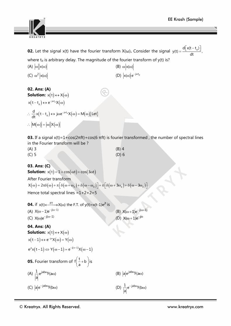
02. Let the signal x(t) have the fourier transform X(ω). Consider the signal dd x(t t )
y(t) ,dt
where td is arbitrary delay. The magnitude of the fourier transform of y(t) is?
(A) x( ) (B) x( )
(C) 2 x( ) (D) dj tx( ) e
02. Ans: (A)
Solution: x t X
d
d
j t
d
j t
d
x t t e X
dx t t j e X M Let
dt
M X
03. If a signal x(t)=1+cos(2πft)+cos(6 πft) is fourier transformed , the number of spectral lines
in the Fourier transform will be ?
(A) 3 (B) 4
(C) 5 (D) 6
03. Ans: (C)
Solution: x t 1 cos t cos 3 t
After Fourier transform
0 0 0 0X 2 3 3
Hence total spectral lines =1+2+2=5
04. if jtFTx(t) X( ) the F.T. of y(t)=x(t-1)e is
(A) j( 1)
X( 1)e
(B) j( 1) X( 1)e
(C) j( 1) X( )e
(D) j
X( 1)e
04. Ans: (A)
Solution: x t X
j
j 1jt
x t 1 e X Y
e x t 1 Y 1 e X 1
05. Fourier transform of t
f ba
is
(A) jab1e F(a )
a
(B)
jaba e F(a )
(C) jab
a e F(b )
(D) jab1e F(b )
a
EE Krash (Sample)
© Kreatryx. All Rights Reserved. www.kreatryx.com
05. Ans: (B)
Solution: t
f ba
jb
Let f t F
Y f t b e F .....................(1)
1
Note; If f t F Then f at Faa
jab
From Equation (1)
tf b a e F a
a
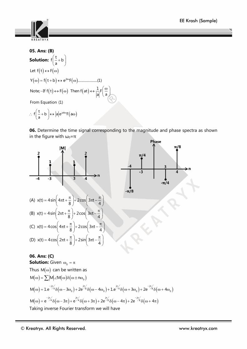
06. Determine the time signal corresponding to the magnitude and phase spectra as shown
in the figure with ω0=π
(A) x(t) 4sin 4 t 2cos 3 t8 4
(B) x(t) 4sin 2 t 2cos 3 t8 4
(C) x(t) 4cos 4 t 2cos 3 t8 4
(D) x(t) 4cos 2 t 2sin 3 t8 4
06. Ans: (C)
Solution: Given 0
Thus M can be written as
0
j jj j8 84 4
0 0 0 0
j jj j8 84 4
M M M n
M 1.e 3 2e 4 1.e 3 2e 4
M e 3 e 3 2e 4 2e 4
Taking inverse Fourier transform we will have

EE Krash (Sample)
© Kreatryx. All Rights Reserved. www.kreatryx.com
j jj j
j3 t j3 t j4 t j4 t8 84 4M t e .e e .e 2e .e 2e .e
j 3 t j 3 t j 4 t j 4 t
4 4 8 8M t e e 2 e e
M t 2cos 3 t 4cos 4 t4 8
07. The signal x(t) is shown as
Then the inverse Laplace transform of X2(s) is?
07. Ans: (D)
Solution: Given x(t)

EE Krash (Sample)
© Kreatryx. All Rights Reserved. www.kreatryx.com
Now 1L X s X s x t * x t
1L X s X s
08. For the signal shown below
(A) Only Fourier transform exists
(B) Only Laplace transform exists
(C) Both Laplace and Fourier transforms exists
(D) Neither Laplace nor Fourier transforms exists
08. Ans: (B)
Solution: Given ty t e u t
Fourier transform will not exist as y t dt
Laplace will exist for 1 0 => >1
09. Find the Inverse Fourier transform of X(ω) for the magnitude and phase spectra of X(ω)
(A) 0
A1 cos t
(B) 0
A1 cos t
t
(C) 0
A1 sin t
(D) 0
A1 sin t
t
09. Ans: (B)
Solution: j t1x t X e d
2 j

EE Krash (Sample)
© Kreatryx. All Rights Reserved. www.kreatryx.com
0 0
0 0
0 0j jj t j t j t j t2 2
0 0
1 1x t X e dt X e d Ae e d A e e d
2 j 2 j
0
0 0
0
0j t j t j tj t
j j j j02 2 2 2
e 1 e e 1eA Ax t e . e . e e
2 j jt jt 2 j jt jt
0 0j t j tj j
2 22 2 02jsin 2jsin tA e e e e A 2 2
x t2 j jt 2 j jt
0
Ax t 1 cos t
t
10. Find the inverse Fourier transform of the spectra F(ω) depicted below
(A) 24sinc (t)cos4t
(B) 22
sinc (t)cos4t
(C) 22sinc (t)sin4t
(D) 24
sinc (t)sin4t
10. Ans: (B)
Solution: Since we know that
F.Ttx(t) A
T
AT 2 T
sinc2
Thus using duality principle
2 F.TtTAT sinc 2 x
2
For T=2 and A=1

EE Krash (Sample)
© Kreatryx. All Rights Reserved. www.kreatryx.com
2 F.T2sinc t
2 F.T1sinc t
2 F.T2x(t) sinc t
Now, the given graph of F can be obtained as
4 jt 4 jt
IFTX 4 X 4 x t e x t eF x t cos4t
2 2
22f t sinc t cos4t
11. Determine the Fourier transform for the waveform shown below
(A) 2 jsin(2 f)(3 e )
f
(B) 2 jsin(2 f)(3 e )
f
(C) 2 jsin(2 f)(3 e )
f
(D) None
11. Ans: (A)
Solution:
Note:- A sinc2

EE Krash (Sample)
© Kreatryx. All Rights Reserved. www.kreatryx.com
f t Can be break as shown
t3rect
2
t
rect 22
3 2sinc 6sinc 2 f j21 2e sinc 2 f
j2 j2 j2
j2
sin2 fF 6sinc 2 f 2e sinc 2 f 2sinc 2 f 3 e 2 3 e
2 f
sin2 fF 3 e
f

EE Krash (Sample)
© Kreatryx. All Rights Reserved. www.kreatryx.com
Engineering Mechanics
Rectilinear Motion
The initial velocity of an object is 40 m/s. The acceleration ‘a’ of the object is given by the
following expression.
a = -0.1 v, Where v is the instantaneous velocity of the object. The velocity of the object after
3 seconds will be _____________
Solution: 29.63 m/s
U 40 m / s a 0.1 V V ? T 3 s Using expression for acceleration
dva 0.1 v
dt
Rearranging and integrating both sides
v 3
40 0
dv0.1dt
v
v
40lnv 0.1 [t]
ln v – ln 40 0.1 3.0 0.3
ln v ln 40 0.3 ln v 3.38887
3.38887v e 29.6327 m/ s
01. A stone is thrown upto a slope of inclination at a speed of V and an angle (beta) to
slope. The stone reaches its greatest distance from the slope after a time of
(a) Vsin
gcos
(b)
Vcos
gsin
(c) Vsin
gcos
(d)
Vcos
gsin
01. Ans: (c)
Solution:
Problems
Sample Problem

EE Krash (Sample)
© Kreatryx. All Rights Reserved. www.kreatryx.com
Take the reference planes as shown
This ‘ gcos ’ will affect the vertical component of the projectile on this reference plane.
i xV Vcos
; i YV Vsin
f f fx YV V ; V 0
Along Y-direction
f i YYV V at
0 Vsin gcos t (Taking -ive sign with gcos it is acting in downward direction)
Vsint
gcos

EE Krash (Sample)
© Kreatryx. All Rights Reserved. www.kreatryx.com
Free body diagram
A mass 35 kg is suspended from a weightless bar AB which is supported by a cable CB and a
pin at A as shown in figure. The pin reactions at A on the bar AB are
(a) Rx = 343.4 N, Ry =755.4 N (b) Rx = 343.4 N, Ry = 0
(c) Rx = 755.4 N, Ry = 343.4 N (d) Rx = 755.4 N, Ry = 0
Solution: (d) is correct option
yT sin R mg
xT cos R
Now, 125
tan275
24.44 Taking moment about A
Tsin mg l l 35 9.81
T 829.74sin 24.44
Rx = 755.4
Ry = 0
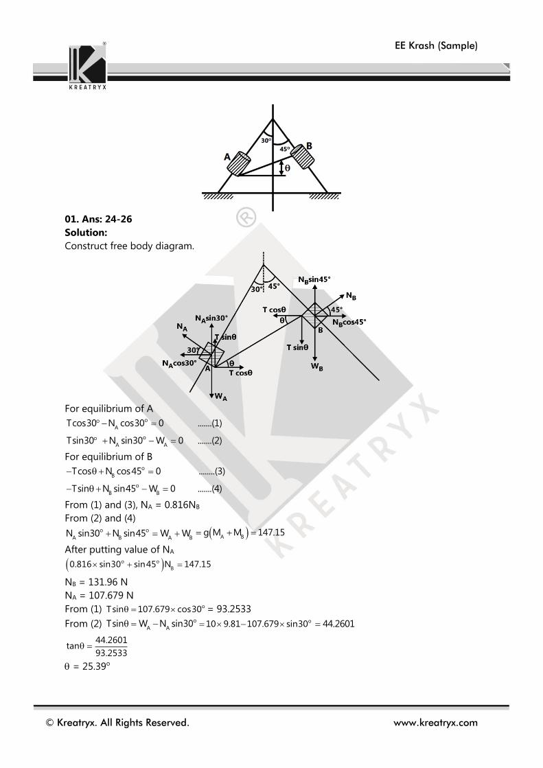
01. The collars A and B hang on vertical frame composed of two smooth rods. If the mass of
collar A is 10 kg and the mass of collar B is 5 kg, determine the equilibrium angle (in
degree)
Problems
Problems
EE Krash (Sample)
© Kreatryx. All Rights Reserved. www.kreatryx.com
01. Ans: 24-26
Solution:
Construct free body diagram.
For equilibrium of A
o
ATcos30 N cos30 0 .......(1)
o
A ATsin30 N sin30 W 0 .......(2)
For equilibrium of B
o
BTcos N cos45 0 ........(3)
o
B BTsin N sin45 W 0 .......(4)
From (1) and (3), NA = 0.816NB
From (2) and (4) o o
A B A BN sin30 N sin45 W W A B
g M M 147.15
After putting value of NA
o o
B0.816 sin30 sin45 N 147.15
NB = 131.96 N
NA = 107.679 N
From (1) oTsin 107.679 cos30 = 93.2533
From (2) o
A ATsin W N sin30 o10 9.81 107.679 sin30 44.2601
44.2601tan
93.2533
= 25.39o

EE Krash (Sample)
© Kreatryx. All Rights Reserved. www.kreatryx.com
Analog Electronics
DC Analysis and Biasing Circuits of BJT
For Concept, refer to Analog Electronics K-Notes, Transistor Biasing and Transistor Amplifiers
The transistor used in the circuit shown below has a β of 30 and ICBO is negligible. If the
forward voltage drop of diode is 0.7 V, then the current through collector will be
(A) 168 mA (B) 108 mA
(C) 20.54 mA (D) 5.36 mA4
Solution: (D) is correct option
Assume that the transistor operated in active region then apply KVL to base-emitter loop.
5-103IB-0.7-0.7+12=0
IB=15.6 mA
IC=0.468 A
Apply KVL to collector-emitter loop
0-2.2K IC - VCE+12=0
VCE=-2200 IC+12=-1017.6 V
As 0<VCE<VCC Not satisfying this condition. Transistor operating in saturation region.
V+(sat)=0.2 V
Apply KVL, 0-2.2IC-0.2+12=0
IC=5.36 mA
Sample Problem
Common Mistake / Point to remember Verify the region of operation of Transistor before calculating the Transistor parameters. While calculating
IC,VCE,VC,IB,IE, open circuit all capacitors and disable AC sources.
For pnp transistor, the analysis remains same as npn transistor but polarity of voltage & direction of
currents are reversed.

EE Krash (Sample)
© Kreatryx. All Rights Reserved. www.kreatryx.com
01. For the circuit shown in the given figure, the quiescent point is
(A) 12V, 5mA (B) 12V, 2mA
(C) 11V, 2mA (D) 10V, 5mA
01. Ans: (C)
Solution:
Let transistor is active region
Assume VBE = 0.7V
IE = 30 0.7
15
= 1.95mA
IE = IC (If large)
Apply KVL
20-5IC – VCE – 15IC+30=0
VCE= 50-20 1.955 = 10.9V
02. Assertion (A): A self-biased BJT Circuit is more stable as compared to a fixed biased one
Reason(R): A self-biased BJT circuit uses more components as compared to a fixed biased
one
(A) Both A and R are true and R is the correct explanation of A
(B) Both A and R are true but R is NOT the correct explanation of A
(C) A is true but R is false
(D) A is false but R is true
02. Ans: (B)
Solution:
For fixed bias stability (S) = + 1
For self bias stability (S) = E
B E
1
R1
R R
(S) self bias < (S) fixed bias
S 1 always
Problems
EE Krash (Sample)
© Kreatryx. All Rights Reserved. www.kreatryx.com
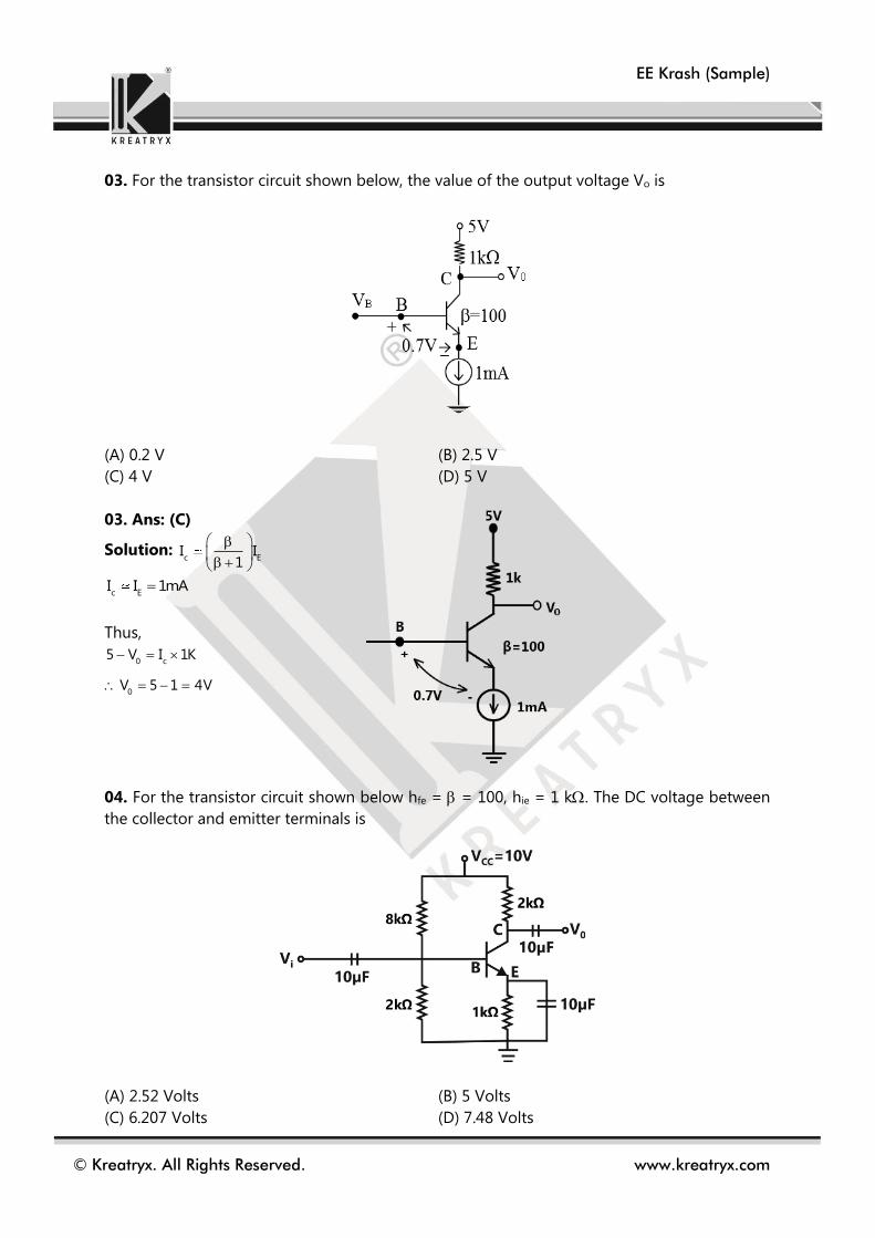
03. For the transistor circuit shown below, the value of the output voltage Vo is
(A) 0.2 V (B) 2.5 V
(C) 4 V (D) 5 V
03. Ans: (C)
Solution: c EI I
1
c EI I 1mA
Thus,
0 c
0
5 V I 1K
V 5 1 4V
04. For the transistor circuit shown below hfe = = 100, hie = 1 k. The DC voltage between
the collector and emitter terminals is
(A) 2.52 Volts (B) 5 Volts
(C) 6.207 Volts (D) 7.48 Volts
EE Krash (Sample)
© Kreatryx. All Rights Reserved. www.kreatryx.com
04. Ans: (C)
Solution: Given β=100
x
E x
2V 10 2V..............(i)
2 8
V V 0.7 1.3V
Thus, E
E
VI 1.3mA
1K
Since β=100
C EI I 1.3mA
Now, we can write
C CE E
CE c
10 2 I V 1 I
V 10 3I 6.1V
DC equivalent circuit
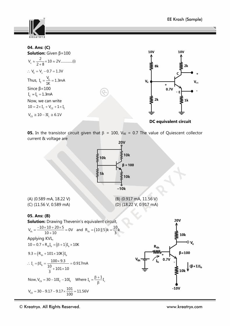
05. In the transistor circuit given that = 100, VBE = 0.7 The value of Quiescent collector
current & voltage are
(A) (0.589 mA, 18.22 V) (B) (0.917 mA, 11.56 V)
(C) (11.56 V, 0.589 mA) (D) (18.22 V, 0.917 mA)
05. Ans: (B)
Solution: Drawing Thevenin’s equivalent circuit,
th th
10 10 20 5 10V 0V and R 10 || 5 k k
10 10 3
Applying KVL,
th b b
th b
10 0.7 R I 1 I 10K
9.3 R 101 10K I
c b
100 9.3I I 0.917mA
10101 10
3
CE C E E c
1Now,V 30 10I 10I Where I I
CE
101V 30 9.17 9.17 11.56V
100

EE Krash (Sample)
© Kreatryx. All Rights Reserved. www.kreatryx.com
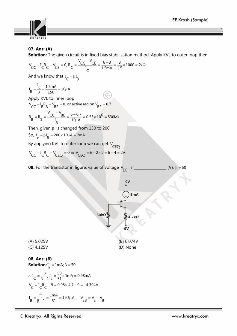
06. In the Series voltage regulator circuit. Given that VZ = 10 V, VBE = 0.7 V, =50. The value
of VCE = ……………….
(A) 20 V (B) 10 V
(C) 9.3 V (D) 10.7 V
06. Ans: (D)
Solution: 20 10
I 10mA1K
BE 0also, V 0.7 10 V 0.7
0V 9.3V
CE 0V 20 V 10.7V
07. In the amplifier circuit shown in the figure, the values of R1 and R2 are such that the
transistor is operating at V 3V and I 1.5mACE C
when it’s is 150. If the of the transistor
is 200, then the operating voltage VCE
(in volts) is
(A) 2 V (B) 3 V
(C) 4 V (D) 5 V
EE Krash (Sample)
© Kreatryx. All Rights Reserved. www.kreatryx.com
07. Ans: (A)
Solution: The given circuit is in fixed bias stabilization method. Apply KVL to outer loop then
V V6 3 3CC CEV I R V 0, R 1000 2k
CC C C CE C I 1.5mA 1.5C
And we know that I IC B
I1.5mAcI 10 A
B 150
Apply KVL to inner loop
V I R V 0. or active region V 0.7CC B B BE BE
V V6 0.7 6CC BER R 0.53 10 530K
B 1 I 10 AB
Then, given is changed from 150 to 200.
So, I I 200 10 A 2mAc B
By applying KVL to outer loop we can get VCEQ
V I R V 0 V 6 2 2 6 4 2VCC C C CEQ CEQ
08. For the transistor in figure, value of voltage VEC
is __________________ (V). 50
(A) 5.025V (B) 6.074V
(C) 4.125V (D) None
08. Ans: (B)
Solution: I 1mA; 50E
50I I 1mA 0.98mAC E1 51
V I R 9 0.98 4.7 9 4.394VC C C
I 1mAEI 19.6 A, V V VB EB E B1 51

EE Krash (Sample)
© Kreatryx. All Rights Reserved. www.kreatryx.com
3V V V 0.7 50 19.6 10 1.68VE EB B
V V V 1.68 4.394 6.074VEC E C
09. In the circuit shown in figure, the transistor has current gain of 100 and VBE = 0.7V. The
current flowing through 5 k load (in mA) is _________________.
09. Ans: 0.7825
Solution:
Step (1):
KVL for B-E loop:
B B BE E E EE0 I R V I R V 0
B B B E EE BEI R 1 I R V V
B
5 0.7I
10k 101 5k
8.3 A
C BI I 0.835 mA
Step (2):
KCL at node ‘C’
C LI I I
0 012 V V
0.835m5k 5k
0
1 12.4m 0.835m V
5k 5k
0
1.56m 5kV
2
3.9125V
0
R
VI
5k 0.7825 mA
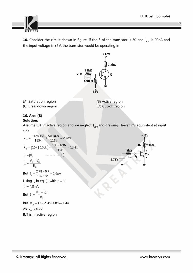
EE Krash (Sample)
© Kreatryx. All Rights Reserved. www.kreatryx.com
10. Consider the circuit shown in figure. If the β of the transistor is 30 and CBO
I is 20nA and
the input voltage is +5V, the transistor would be operating in
(A) Saturation region (B) Active region
(C) Breakdown region (D) Cut-off region
10. Ans: (B)
Solution:
Assume BJT in active region and we neglect CBO
I and drawing Thevenin’s equivalent at input
side
Th
12 15k 5 100kV 2.78V
115k 115k
th
15k 100kR 15k || 100k 13k
115k
c bI I .................. (i)
th BE
b
th
V VI
R
But b 3
2.78 0.7I 1.6 A
13 10
Using bI in eq. (i) with 30
cI 4.8mA
But CC CE
c
C
V VI
R
But CE
V 12 2.2k 4.8m 1.44
As CE
V 0.2V
BJT is in active region

EE Krash (Sample)
© Kreatryx. All Rights Reserved. www.kreatryx.com
Electrical Machine
Equivalent Circuit of Transformer
For Concept, refer to Electrical Machines K-Notes, Transformers
A Single-phase transformer has a turns ratio 1:2, and is connected to a purely resistive load
as shown in the figure. The magnetizing current drawn is 1 A, and the secondary current is 1
A. If core losses and leakage reactance’s are neglected, the primary current is
(A) 1.41 A
(B) 2 A
(C) 2.24 A
(D) 3 A
Solution: (C) is correct option
I0 = 1 amp (magnetizing current)
Primary current IP = ?
I2 = 1 A
I2p = secondary current referred to Primary
2 2
p
p
2
2
o p
21 2 amp
1
I i i 1 4 2.24 amp
I
01. Across the HV side of a single phase 200 V / 400 V, 50 Hz transformer, an impedance of
32 + j24Ω is connected, with LV side supplied with rated voltage & frequency. The supply
current and the impedance seen by the supply are respectively:
(A) 20 A & (128 + j96)Ω
(B) 20 A & (8 + j6)Ω
(C) 5 A & (8 + j6)Ω
(D) 20 A & (16 + j12)Ω
Problems
Sample Problem
Common Mistake / Point to remember
Sometimes we add primary current to no-load current as scalar though they must be added as phasors.

EE Krash (Sample)
© Kreatryx. All Rights Reserved. www.kreatryx.com
01. Ans: (B)
Solution: 2
Z 32 j24
T
400a 2
200
So load impedance seen by primary side 2
2 2
T
ZZ 8 j6
a
Current at supply side200
8 j6
020 36.86
02. Consider the circuit shown below
If the ideal source supplies 1000W, half of which is delivered to the 100 Ω load, then the
value of b is____
(A) 1.5 (B) 0.89
(C) 0.56 (D) 0.67
02. Ans: (B)
Solution:
Since source is supplying 1000W
So current from voltage source 1
1000I 10A
100
Since 500W is delivered to 100Ω resistor 2
3 3I 100 500 I 5A
Power consumed in 4Ω resistor= 2
10 4 400W
Total power consumed=Power consumed is 4Ω+power consumed in 25Ω+Power consumed
in 100Ω
Power consumed in 25Ω=1000-500-400=100W 2
2I 25 100
2I 2A

EE Krash (Sample)
© Kreatryx. All Rights Reserved. www.kreatryx.com
Since 2
3
I b
I 1
2
3
I 2b 0.89433
I 5
03. A 1200/300, turns transformer when loaded, current on the secondary is 100A at 0.8
power factor lagging and primary current is 50A at 0.707 power factor lagging. Determine
the no-load current of the transformer with respect to the voltage?
(A) 25.5A (B) 26.5A
(C) 27.5A (D) 28.5A
03. Ans: (A)
Solution: T
1200a 4
300
Taking voltages at reference phasor
Then 1
2I 100 cos 0.8 0100 36.86
0
2
2
I 100 36.86I
a 4
025 36.86 A
1
1I 50 cos 0.707
050 45 A
No load current 0 1 2I I I 0 0 050 45 25 36.86 25.5 52.97

EE Krash (Sample)
© Kreatryx. All Rights Reserved. www.kreatryx.com
Salient Pole Synchronous Machines
For Concept, refer to Electrical Machines K-Notes, Synchronous Machines
The direct axis and quadrature axis reactance’s of a salient pole alternator are 1.2 p.u and 1.0
p.u respectively. The armature resistance is negligible. If this alternator is delivering rated kVA
at upf and at rated voltage then its power angle is
(A) 30° (B) 45°
(C) 60° (D) 900
Solution: (B) is correct option
Power angle for salient pole alternator is given by
t a q
t a a
V sin I Xtan
V cos I R
Since the alternator is delivering at rated kVA rated voltage
a tI 1 pu , V 1 pu,
00 ,sin 0, cos 1
0
q d
Since 0 , =
X = 1 pu, X = 1.2 pu
0
1
45
1 0 1 1tan
1 0
01. A 1500KVA, star connected 6.6KV salient pole synchronous motor has Xd = 23.2 and
Xq= 14.5/ph respectively. Armature resistance is negligible. The excitation emf (line value)
when the motor is supplying rated load at 0.8 lead P.F. is.
(A) 6.1KV (B) 10.57KV
(C) 15KV (D) 18.3KV
Problems
Sample Problem
Common Mistake / Point to remember
While using EMF – Terminal Voltage Equation direct axis and quadrature axis currents, make sure that you
treat them as phasors and use their phase angles as well.

EE Krash (Sample)
© Kreatryx. All Rights Reserved. www.kreatryx.com
01. Ans: (B)
Solution: S=1500KVA, V=6.6kV, d qX 23.2 & X 14.5
a fr 0,e ? at 0.8 lead p.f
t a
6.6K 1500KV 3810,I 131A
3 6.6K 3
f t d de V cos I X
d aI I sin
t a q
t a a
V sin I Xtan
V cos I r
3810 0.6 131 23.21.747
3810 0.8
060.214
36.87 0
d
23.34 ,
I 131sin60.214 113.69
fe 3810cos 23.34 113.61 23.2 6135V
fL L fe 3e 10.62kV
02. A 50-Hz, 3-phase, 480-V, delta connected salient pole synchronous generator has xd =
0.1 ohm and xq = 0.075 ohm. The generator is supplying 1200 Amp. at 0.8 p.f. lagging. The
load angle is
(A) 41.5o (B) 14.5o
(C) 4.6o (D) 6.4o
02. Ans: (C)
Solution: V=480V, d qX 0.1 ,X 0.075
aI 1200A at 0.8 lag
a/p
1200I 692.82A
3 [delta connection]
t a q
t a a
V sin I Xtan
V cos I r
480 0.6 692.82 0.075.885
480 0.8
041.5 04.6
03. A 10KVA, 380V, 50Hz, 3- star connected salient pole alternator has direct axis and
quadrature axis reactance’s of 12 and 8 respectively. The armature has a resistance of 1
per phase. The generator delivers rated load at 0.8 p.f lagging with the terminal voltage
being maintained at rated value. Find the direct axis component of armature current, if the
load angle is 16.15
(A) 12.14A (B) 9.14A
(C) 14.21A (D) 5.37A

EE Krash (Sample)
© Kreatryx. All Rights Reserved. www.kreatryx.com
03. Ans: (A)
Solution: 10KVA, 380V, d q aX 12 & X 8 ,r 1
Pf=0.8 lag, t
V Constant , 0
t
38016.15 ,V 220V
3
a
10KI 15.193A
380 3
220 .6 15.193 8tan 1.326
220 .8 15.193 1
053
d aI I sin 12.14A
04. In a 3 phase, salient pole synchronous generator with the ‘a’ phase terminal voltage of0
V 0 volts, the phase current delivered by the machine is 30A, lagging the terminal voltage by
300. The induced emf per phase is at angle 150 from the terminal voltage. The currents Id and
Iq are, respectively
(A) 0 015 90 A, 26 0 A (B) 030 30 A, 0A
(C) 0 029 15 A, 7.76 105 A (D) 0 021.21 75 A, 21.21 15 A
04. Ans: (D)
Solution: aI 30A , p.f=0.866lag,
0
q d15 ,I and I ?
0 0 030 15 45
q aI I cos 21.21A
d aI I sin 21.21A
w.r.t V, 0
qI 21.21 15 [aligned with
fe ]
0
dI 21.21 75 [
fto E ]

EE Krash (Sample)
© Kreatryx. All Rights Reserved. www.kreatryx.com
Power Electronics
Buck Converter
For Concept, refer to Power Electronics K-Notes, Chopper
A buck converter, as shown in Figure (a) below, is working in steady state. The output voltage
and the inductor current can be assumed to be ripple free. Figure (b) shows the inductor
voltage during a complete switching interval. Assuming all devices are ideal, the duty
cycle of the buck converter is ___________.
Solution: 0.4
Voltage wave shape across inductor is shown below,
vL
Sample Problem
Common Mistake / Point to remember
For approximate ripple in Inductor Current we can directly use the concept of Voltage across the inductor
so no need to memorize the formulas for maximum and minimum current in chopper.
Instead of memorizing expression for different parameters of converter, better understand the method to
derive such parameters.
For discontinuous conduction replace D by D
in every expression.

EE Krash (Sample)
© Kreatryx. All Rights Reserved. www.kreatryx.com
Since average voltage across the inductor should be zero over a cycle,
Duty cycle
Therefore,
01. A step down chopper feeding an inductive load and current is ripple free in the output
circuit. The ratio of average currents through freewheeling diode and chopper is ____ (Take
duty cycle D=0.8)
(A) 0.25 (B) 4
(C) 2 (D) 0.5
01. Ans: (A)
Solution: Chopper current ch 0I DI
FD current F.D 0I 1 D I
F.D.
ch
1 DI 1 0.80.25
I D 0.8
02. Type-A chopper supplies power to a resistive load of 10 from 200 V dc source. The
output voltage is ON for 4 ms duration and OFF for 6 ms duration. The rms value of
fundamental component of output voltage is
(A) 80 V (B) 126.5 V
(C) 90 V (D) 85.6 V
02. Ans: (D)
Solution: on
on off
T 4D 0.4
T T 4 6
For Type A chopper
RMS value of fundamental component of output voltage
dc
01
2V 2 200V sin D sin 0.4 85.625V
2 2
L avgV 0
T
L
0
V dt 0
on offT T
0 0
30dt 20dt 0
on off30T 20T 0
off on
3T T
2
on
total
TD
T on
on off
T
T T
on
on on
T
3T T
2
20.4
5
duty cycle 0.4
Problems

EE Krash (Sample)
© Kreatryx. All Rights Reserved. www.kreatryx.com
03. A step down DC chopper feeding a resistive load of R = 20 and input voltage =220 V.
When the chopper remains ON, it’s voltage drop is 1.5 V and chopping frequency is 10 KHz.
What is the chopper efficiency?
(A) 99.3 % (B) 89%
(C) 99% (D) 98.3%
03. Ans: (A)
Solution: i/p S 0 0
i/p S 0
P loss DV I D 1.5 I 218.599.3%
P DV I 220
Here, source conducts for DT where T is switching time period.
04. A DC chopper circuit is connected to a 120 V DC source supplies to inductive load having
50mH in series with a resistance of 6. A Freewheeling diode is placed across the load. The
load current varies between the limits of 12 A and 16 A. Time ratio (Ton / Toff) of chopper is
(A) 2.122 (B) 1.222
(C) 2.333 (D) 1.732
04. Ans: (C)
Solution: For a Buck converter
max min
0 avg
I I 12 16I I 14A
2 2
0 avg avg
0 S
V V I R 14 6 84
V DV
ON
OFF
84 120 D =>D 0.7
T DT D 0.72.33
T 1 D 1 0.71 D T
05. A simple D.C chopper is operating at a frequency of 4 kHz from a 100V DC source to
supply a load resistance of 6. The load time constant is 6ms, average load voltage is 62 V.
Assume load current variations are linear. Magnitude of ripple current is
(A) 0.127 A (B) 0.164 A
(C) 0.237 A (D) 0.282 A
05. Ans: (B)
Solution: For a Buck converter
0 SV DV => 62 D 100
D 0.62
Load Time constant 3 3L6 10 =>L 36 10
R
Magnitude of ripple S
V 1 D DTI
L
3 3
100 1 0.62 0.62I 0.164A
36 10 4 10
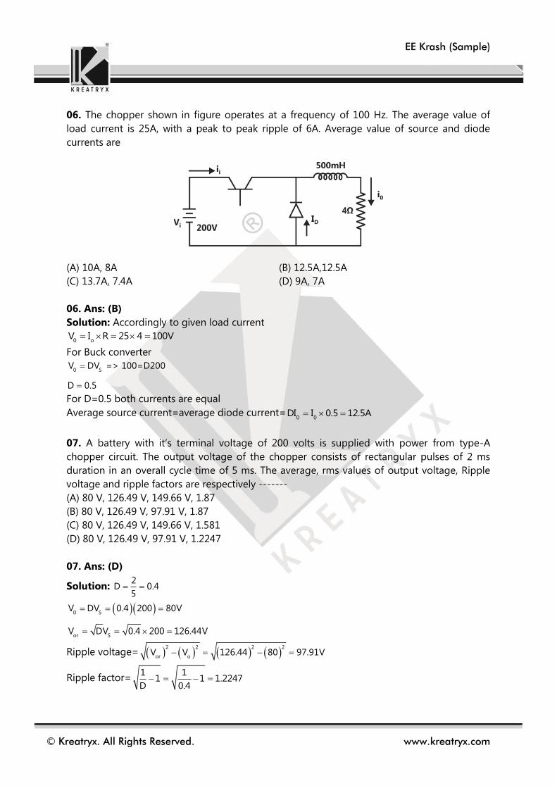
EE Krash (Sample)
© Kreatryx. All Rights Reserved. www.kreatryx.com
06. The chopper shown in figure operates at a frequency of 100 Hz. The average value of
load current is 25A, with a peak to peak ripple of 6A. Average value of source and diode
currents are
(A) 10A, 8A (B) 12.5A,12.5A
(C) 13.7A, 7.4A (D) 9A, 7A
06. Ans: (B)
Solution: Accordingly to given load current
0 oV I R 25 4 100V
For Buck converter
0 SV DV => 100=D200
D 0.5
For D=0.5 both currents are equal
Average source current=average diode current=0 0
DI I 0.5 12.5A
07. A battery with it’s terminal voltage of 200 volts is supplied with power from type-A
chopper circuit. The output voltage of the chopper consists of rectangular pulses of 2 ms
duration in an overall cycle time of 5 ms. The average, rms values of output voltage, Ripple
voltage and ripple factors are respectively -------
(A) 80 V, 126.49 V, 149.66 V, 1.87
(B) 80 V, 126.49 V, 97.91 V, 1.87
(C) 80 V, 126.49 V, 149.66 V, 1.581
(D) 80 V, 126.49 V, 97.91 V, 1.2247
07. Ans: (D)
Solution: 2
D 0.45
0 S
or S
V DV 0.4 200 80V
V DV 0.4 200 126.44V
Ripple voltage= 2 2 2 2
or oV V 126.44 80 97.91V
Ripple factor=1 1
1 1 1.2247D 0.4

EE Krash (Sample)
© Kreatryx. All Rights Reserved. www.kreatryx.com
08. A load is operating in a chopper circuit as shown in the figure. It has a duty cycle of 0.4
and chopping frequency is 150 Hz. (consider continuous operation). The value of E is _______.
(A) 70V (B) 80V
(C) 60V (D) 50V
08. Ans: (B)
Solution: Under steady state condition the average voltage drop across L is zero.
So, in that case
in
s
V E
E DV 0.4 200V 80V
09. Given, s 0
V 20V, V 50V, R 50 , D 0.5
Find average inductor current and ripple in inductor current.
(A) 2.5A, 5A
(B) 2.5A, 4A
(C) 2.5A, 6A
(D) 6A, 2.5A
09. Ans: (C)
Solution:
s
0
V 20V 40V
1 D 1 0.5
, 0
V given 50V 40V (discontinuous)

EE Krash (Sample)
© Kreatryx. All Rights Reserved. www.kreatryx.com
s
0
V 20V 50
D 0.5
30 25
25 5
30 6
Average inductor current
C on C offI T I T 0
0 L 0I DT I I D T 0
0 L L 0 0I DT I T I DT I T I DT 0
L L 0I I D I
0
L
0
0
II
D
V 50I 1 A
R 50
L L
1 5/6I 2.5A I avg
5/6 0.5
L
L avg
1I T
2IT
L
12.5 I
2
L
2.5 2I A 6A
5/6
10. Given, s 0
V 20V, V 50V, R 50 , D 0.5
Find average diode and switch current.
(A) 2A, 2.5A
(B) 1A, 1.5A
(C) 2.5A, 2A
(D) 1.5A, 1A
10. Ans: (B)
Solution:
s
0
V 20V 40V
1 D 1 0.5
0V given 50V 40V , discontinuous mode.

EE Krash (Sample)
© Kreatryx. All Rights Reserved. www.kreatryx.com
s
0
VV
D
2050
0.5
5
6
Applying Ampere-sec balance
C on C offI T I T 0
0
0
V 50I 1A
R 50
0 L 0I DT I I D T 0
0
L
51I 6I 2.5A
5D0.5
6
L
L avg
1I T
2IT
L
12.5 I
2
L
I 6 A
Average diode current
L
1I D T
1 52 6 0.5 1 AT 2 6
Average switch current
L
1I DT
12 6 0.5 1.5 AT 2
11. A boost converter has input voltage of 5V and average output voltage of 15V. The
switching frequency is 20 KHz and load resistance is 15 .
Find ripple in capacitor voltage C 20 F
(A) 1.5V (B) 1.6V
(C) 1.67V (D) 1.95V
11. Ans: (C)
Solution:
s
0
V 5 1 2V 15 1 D D
1 D 1 D 3 3
Load current 15
1 A15
.
Ripple in capacitor voltage
C
C 0
DVdvC I C I
dt DT (discharging)
0
C 6 3
21I D 23V 1.67V
Cf 3 0.420 10 20 10