Embed Size (px)
Citation preview
K-MC3 RADAR TRANSCEIVER Datasheet
Features
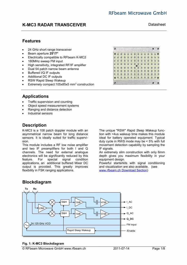
24 GHz short range transceiver Beam aperture 25°/7° Electrically compatible to RFbeam K-MC2 180MHz sweep FM input High sensitivity, integrated RF/IF amplifier Dual 54 patch narrow beam antenna Buffered I/Q IF outputs Additional DC IF outputs RSW Rapid Sleep Wakeup Extremely compact:105x85x5 mm3 construction
Applications Traffic supervision and counting Object speed measurement systems Ranging and distance detection Industrial sensors
DescriptionK-MC3 is a 108 patch doppler module with anasymmetrical narrow beam for long distancesensors. It is ideally suited for traffic supervi-sion. This module includes a RF low noise amplifierand two IF preamplifiers for both I and Qchannels. The need for external analogueelectronics will be significantly reduced by thisfeature. For special signal conditionapplications, an additional buffered Mixer DCoutput is provided. This greatly improvesflexibility in FSK ranging applications.
The unique "RSW" Rapid Sleep Wakeup func-tion with <4us wakeup time makes this moduleideal for battery operated equipment. Typicalduty cycle in RWS mode may be < 5% with fullmovement detection capability by sampling theIF signals. An extremely slim construction with only 6mmdepth gives you maximum flexibility in yourequipment design. Powerful starterkits with signal conditioningand visualization are also available. (see www.rfbeam.ch Download Section)
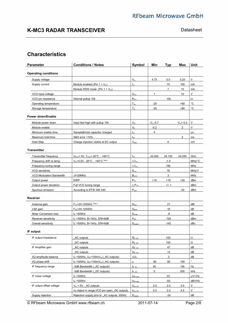
Blockdiagram
Fig. 1: K-MC3 Blockdiagram
© RFbeam Microwave GmbH www.rfbeam.ch 2011-07-14 Page 1/8
Tx Rx
24.125 GHz VCO
S&H
S&H
Rapid Sleep Wakeup
I_AC
I_DC
Q_AC
Q_DCQ_DC
/Enable
FM input
LNA
47dB15dB
15dB 47dB
K-MC3 RADAR TRANSCEIVER Datasheet
Characteristics
Parameter Conditions / Notes Symbol Min Typ Max Unit
Operating conditions
Supply voltage Vcc 4.75 5.0 5.25 V
Supply current Module enabled (Pin 1 = VIL) Icc 70 100 mA
Module RSW mode (Pin 1 = VIH) 7 10 mA
VCO input voltage Uvco 1 10 V
VCO pin resistance Internal pullup 10k Rvco 10k
Operating temperature Top -20 +80 °C
Storage temperature Tst -20 +80 °C
Power down/Enable
Module power down Input tied high with pullup 10k VIH Vcc -0.7 Vcc+ 0.3 V
Module enable VIL -0.2 2 V
Minimum enable time Sample&Hold capacitor charged ton 4 s
Maximum hold time S&H error <10% toff 2 ms
Hold Step Charge injection visible at DC output Vstep 6 mV
Transmitter
Transmitter frequency UVCO= 5V, Tamb=-20°C .. +60°C fTX 24.050 24.150 24.250 GHz
Frequency drift vs temp. Vcc=5.0V, -20°C .. +60°C Note 1 fTX -1.0 MHz/°C
Frequency tuning range fvco 180 MHz
VCO sensitivity Svco 18 MHz/V
VCO Modulation Bandwidth f=20MHz BVCO 3 MHz
Output power EIRP PTX +16 +19 +20 dBm
Output power deviation Full VCO tuning range PTX +/- 1 dBm
Spurious emission According to ETSI 300 440 Pspur -30 dBm
Receiver
Antenna gain FTX=24.125GHz Note 2 GAnt 21 dBi
LNA gain FRX=24.125GHz GLNA 16 dB
Mixer Conversion loss fIF =500Hz Dmixer -6 dB
Receiver sensitivity fIF =500Hz, B=1kHz, S/N=6dB PRX -126 dBm
Overall sensitivity fIF =500Hz, B=1kHz, S/N=6dB Dsystem -145 dBc
IF output
IF output impedance _AC outputs RIF_AC 100
_DC outputs RIF_DC 100
IF Amplifier gain _AC outputs GIF_AC 47 dB
_DC outputs GIF_DC 15 dB
I/Q amplitude balance fIF =500Hz, UIF=100mVpp (_AC outputs) UIF 3 dB
I/Q phase shift fIF =500Hz, UIF=100mVpp (_AC outputs) 80 90 100 °
IF frequency range -3dB Bandwidth (_AC outputs) fIF_AC 40 15k Hz
-3dB Bandwidth (_DC outputs) fIF_DC 0 500 kHz
IF noise voltage fIF =500Hz UIFnoise 22 V/Hz
fIF =500Hz UIFnoise -93 dBV/Hz
IF output offset voltage Vcc = 5V, _AC outputs Uos_AC 2.0 2.5 3.0 V
no object in range,VCO pin open,_DC outputs Uos_DC 0.5 2.5 4.5 V
Supply rejection Rejection supply pins to _AC outputs, 500Hz Dsupply -24 dB
© RFbeam Microwave GmbH www.rfbeam.ch 2011-07-14 Page 2/8
K-MC3 RADAR TRANSCEIVER Datasheet
Parameter Conditions / Notes Symbol Min Typ Max Unit
Antenna
Horizontal -3dB beamwidth E-Plane W 7 °
Vertical -3dB beamwidth H-Plane W 25 °
Horiz. sidelobe suppression D -20 dB
Vert. sidelobe suppression D -18 dB
Body
Outline Dimensions connector left unconnected 105x85x5 mm3
Weight 102 g
Connector Module side: AMP X-338069-8 8 pinsNote 1 Transmit frequency stays within 24.050 to 24.250GHz over the specified temperature range if VCO pin is left open Note 2 Theoretical value, given by design
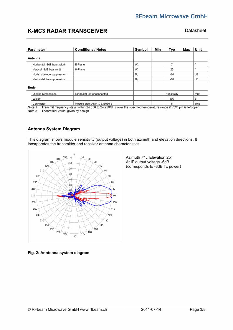
Antenna System Diagram
This diagram shows module sensitivity (output voltage) in both azimuth and elevation directions. It incorporates the transmitter and receiver antenna characteristics.
Azimuth 7° , Elevation 25°At IF output voltage -6dB (corresponds to -3dB Tx power)
Fig. 2: Anntenna system diagram
© RFbeam Microwave GmbH www.rfbeam.ch 2011-07-14 Page 3/8
-70
-60
-50
-40
-30
-20
-10
00
1020
30
40
50
60
70
80
90
100
110
120
130
140
150160
170180
190200
210
220
230
240
250
260
270
280
290
300
310
320
330340
350

K-MC3 RADAR TRANSCEIVER Datasheet
FM Characteristics
Carrier frequency can be modulated by means of a voltage applied to the VCO input.This feature can be used for ranging applications using FMCW ( see also Fig. 4) or FSK techniques. FMCW needs good linearity in the frequency ramp. RFbeam provides a downloadable tool "VCO-Lin" that allows calculating the non-linearity using 3 known frequency versus VCO voltage points.
Fig. 3: Typical Frequency vs. VCO voltage
Pin Configuration
Pin Description Typical Value1 /Enable GND: module active2 VCC 5V supply3 GND 0V supply4 IF output Q_AC high gain output5 IF output I_AC high gain output6 VCO in 2.0V = f0
7 IF output I_DC low gain output8 IF output Q_DC Low gain output
Outline Dimensions
Fig. 4: Mechanical dimensions
© RFbeam Microwave GmbH www.rfbeam.ch 2011-07-14 Page 4/8
K-MC3 RADAR TRANSCEIVER Datasheet
Application Notes
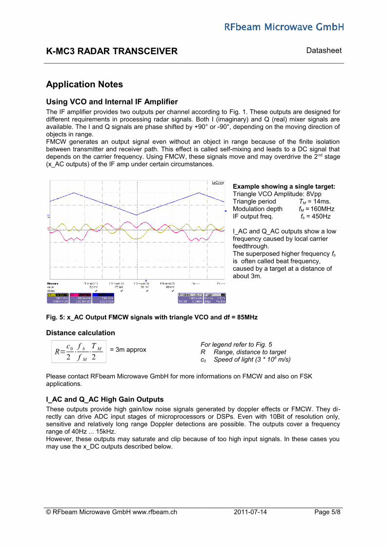
Using VCO and Internal IF AmplifierThe IF amplifier provides two outputs per channel according to Fig. 1. These outputs are designed fordifferent requirements in processing radar signals. Both I (imaginary) and Q (real) mixer signals areavailable. The I and Q signals are phase shifted by +90° or -90°, depending on the moving direction ofobjects in range. FMCW generates an output signal even without an object in range because of the finite isolationbetween transmitter and receiver path. This effect is called self-mixing and leads to a DC signal thatdepends on the carrier frequency. Using FMCW, these signals move and may overdrive the 2nd stage(x_AC outputs) of the IF amp under certain circumstances.
Example showing a single target:Triangle VCO Amplitude: 8VppTriangle period TM = 14ms. Modulation depth fM = 160MHz IF output freq. fb = 450Hz
I_AC and Q_AC outputs show a low frequency caused by local carrier feedthrough.The superposed higher frequency fb is often called beat frequency, caused by a target at a distance of about 3m.
Fig. 5: x_AC Output FMCW signals with triangle VCO and df = 85MHz
Distance calculation
R=c02
⋅f bf M
⋅T M2
= 3m approxFor legend refer to Fig. 5R Range, distance to targetc0 Speed of light (3 * 108 m/s)
Please contact RFbeam Microwave GmbH for more informations on FMCW and also on FSK applications.
I_AC and Q_AC High Gain OutputsThese outputs provide high gain/low noise signals generated by doppler effects or FMCW. They di-rectly can drive ADC input stages of microprocessors or DSPs. Even with 10Bit of resolution only,sensitive and relatively long range Doppler detections are possible. The outputs cover a frequencyrange of 40Hz ... 15kHz.However, these outputs may saturate and clip because of too high input signals. In these cases youmay use the x_DC outputs described below.
© RFbeam Microwave GmbH www.rfbeam.ch 2011-07-14 Page 5/8

K-MC3 RADAR TRANSCEIVER Datasheet
I_DC and Q_DC Low Gain OutputsThe low gain DC outputs (I_DC and Q_DC) hardly enter into a saturation state and may be used in cases, where the high gain outputs (I_AC and Q_AC) are clipped because of high input signals. Satu-ration and clipping typically arise in conjunction with FMCW and may be caused by objects nearby the sensor, non-compensated radoms etc. These outputs carry more signal information than the x_AC outputs because of their bandwidth rang-ing from DC to 500kHz. Using ADCs with resolutions of 12Bits and more and processing with DSP processors allow versatile and flexible radar applications.
Rapid Sleep Wakeup (RSW)RFbeam's unique rapid sleep wakeup feature allows power savings of more than 90% during 'silent'periods. The module may be used in a relaxed sampling mode as long as no movements are de -tected. RSW also helps saving power, if not the full IF bandwidth of 15kHz is needed.In battery operated equipment such as traffic control, RSW may significantly lower battery and equip -ment volume and cost.
RSW in ActionThis graph shows the sampling signal at pin /Enableand a resulting output signal at an x_AC pin causedby an approaching object.This signal may be processed 'as is' or used as trig-ger to start continuous acquisition.If RSW mode is used only to detect any movement,aliasing effects are not important (i.e. undersamplingis useful).By choosing a sampling frequency, aliasing must betaken into account, if frequency measurements areintended.
Fig. 6: Sampled Doppler signal at x_AC outputs
RSW principleRSW combines switching of the RF oscillator and sample&hold of the mixer signals (please refer toFig. 1: K-MC3 Blockdiagram). During sleep mode (pin /ENABLE = high), only the amplifiers stay switched on to hold the output voltage and coupling capacitor charges. This assures minimum peaks at the outputs when returning to the active state. Nevertheless, we have to take some important effects into account. An important effect is charge injection, caused by the digital control signal.
/ENABLE signal with ton = 7µs.
x_AC output signal recovers after 80µs approx.
Fig. 7: x_AC output is influenced by charge injection caused by switching signal
© RFbeam Microwave GmbH www.rfbeam.ch 2011-07-14 Page 6/8
"real" output level
charge injection
1µs/div
1 2typical sampling points

K-MC3 RADAR TRANSCEIVER Datasheet
Sampling sequenceTo simplify signal processing sequence, output sampling may be done immediately after /ENABLE goes high (1) or before next /ENABLE (2). Both methods have their advantages and disadvantages: - Sampling point (1) contains a constant overshoot, i.e. sampled output signal becomes shifted by
a constant DC component. There is no loss of sensitivity.- Sampling point (2) corresponds to the real mixer output, as long as sleep time is short enough. But
with longer off times, signal amplitude decreases. As a rule of thumb: with a repeat frequency of 1kHz (duty cycle of 7µs/1ms = 0.7%) amplitude loss is 3dB approx. This situation is shown in the figure below.
Sampling signal (tc = 1ms, ton = 7us)
Output signal decreases during the off-period with a timeconstant of 4.8ms approx.
Fig. 8: x_AC output amplitude decreases during sleep time.
© RFbeam Microwave GmbH www.rfbeam.ch 2011-07-14 Page 7/8
1µs/div
K-MC3 RADAR TRANSCEIVER Datasheet
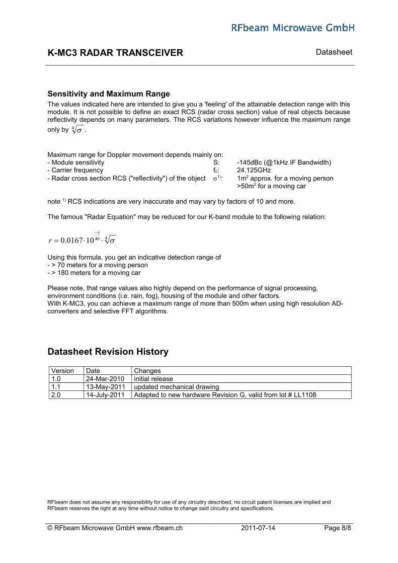
Sensitivity and Maximum RangeThe values indicated here are intended to give you a 'feeling' of the attainable detection range with thismodule. It is not possible to define an exact RCS (radar cross section) value of real objects becausereflectivity depends on many parameters. The RCS variations however influence the maximum range
only by 4 .
Maximum range for Doppler movement depends mainly on:- Module sensitivity S: -145dBc (@1kHz IF Bandwidth)- Carrier frequency f0: 24.125GHz- Radar cross section RCS ("reflectivity") of the object 1): 1m2 approx. for a moving person
>50m2 for a moving car
note 1) RCS indications are very inaccurate and may vary by factors of 10 and more.
The famous "Radar Equation" may be reduced for our K-band module to the following relation:
440100167.0 s
r
Using this formula, you get an indicative detection range of - > 70 meters for a moving person- > 180 meters for a moving car
Please note, that range values also highly depend on the performance of signal processing, environment conditions (i.e. rain, fog), housing of the module and other factors. With K-MC3, you can achieve a maximum range of more than 500m when using high resolution AD-converters and selective FFT algorithms.
Datasheet Revision History
Version Date Changes1.0 24-Mar-2010 initial release1.1 13-May-2011 updated mechanical drawing2.0 14-July-2011 Adapted to new hardware Revision G, valid from lot # LL1108
© RFbeam Microwave GmbH www.rfbeam.ch 2011-07-14 Page 8/8
RFbeam does not assume any responsibility for use of any circuitry described, no circuit patent licenses are implied and RFbeam reserves the right at any time without notice to change said circuitry and specifications.