Embed Size (px)
Citation preview

Dept. of EEE-SVECW (A) BEE&E-UNIT-4
SHRI VISHNU ENGINEERING COLLEGE FOR WOMEN (AUTONOMOUS)
NOTES
ON
UNIT-IV
BASIC ELECTRICAL & ELECTRONICS ENGINEERING
B.Tech. I YEAR - II Sem. (2019-20)
DEPARTMENT OF ELECTRICAL & ELECTRONICS ENGINEERING
SHRI VISHNU ENGINEERING COLLEGE FOR WOMEN
(AUTONOMOUS)
Approved by AICTE & Affiliated to JNTU-K, Kakinada Accredited with ‘A’ Grade by
NAAC & NBA Vishnupur, Bhimavaram, West Godavari Dist. – 534 202, Andhra Pradesh,
India.

Dept. of EEE-SVECW (A) BEE&E-UNIT-4
SHRI VISHNU ENGINEERING COLLEGE FOR WOMEN (AUTONOMOUS)
UNIT-IV: AC MACHINES
Syllabus: Construction and working of three-phase Induction motor, types, slip-torque characteristics. Construction and working of Alternators, types, EMF equation, regulation by synchronous impedance method, (Theoretical Concepts only)
----------------------------------------------------------------------------------------------------------------
Introduction:
Purpose: In convert’s electrical power into mechanical power.
----------------------------------------------------------------------------------------------------------------
Construction of three-phase Induction motor:
An induction motor consists essentially of two main parts:
(a) stator
(b) Rotor

Dept. of EEE-SVECW (A) BEE&E-UNIT-4
SHRI VISHNU ENGINEERING COLLEGE FOR WOMEN (AUTONOMOUS)
(a) Stator
• The stator of an induction motor is the same as that of a synchronous motor (A.C motor) or synchronous generator (A.C. generator).
• Stator is made up of a number of stampings, which are slotted to receive the windings.
Slots
i). Open type ii). Semi-closed type iii). Closed type
The stator carries a 3-phase winding and is fed from a 3-phase supply (as shown in Fig.
29.1). It is wound for a definite number of poles, the exact number of poles being determined by the requirements of speed.
Ns = 120 f/P
f= Frequency of the supply
P=Number of poles.
Greater the number of poles, lesser the speed and vice versa.
The stator windings, when supplied with 3-phase currents, produce a magnetic flux,
which is of constant magnitude but which rotates at synchronous speed (given by Ns =
120 f/P). This revolving magnetic flux induces an e.m.f. in the rotor by mutual induction.
(b) Rotor
(i) Squirrel-cage rotor
(ii) Slip ring rotor or Phase-wound or wound rotor :
(i) Squirrel-cage Rotor:
Almost 90 per cent of induction motors are squirrel-cage type, because this type of rotor has the simplest and most rugged construction imaginable.

Dept. of EEE-SVECW (A) BEE&E-UNIT-4
SHRI VISHNU ENGINEERING COLLEGE FOR WOMEN (AUTONOMOUS)
The rotor consists of a cylindrical laminated core with parallel slots for carrying the rotor conductors which are not wires but consist of heavy bars of copper, aluminium or alloys. One bar is placed in each slot, rather the bars are inserted from the end when semi-closed slots are used.
Slots
1. Open type 2. Semi-closed type 3. Closed type
The rotor bars are electrically welded or bolted to two heavy and stout short-circuiting end-rings.
It should be noted that the rotor bars are permanently short-circuited on themselves,
hence it is not possible to add any external resistance in series with the rotor circuit for starting purposes.
The rotor slots are usually not quite parallel to the shaft but are purposely given a slight skew. This is useful in two ways:
(i) It helps to make the motor run quietly by reducing the magnetic hum and
(ii) it helps in reducing the locking tendency of the rotor (ii)Phase-wound
Rotor:

Dept. of EEE-SVECW (A) BEE&E-UNIT-4
SHRI VISHNU ENGINEERING COLLEGE FOR WOMEN (AUTONOMOUS)
This type of rotor is provided with 3-phase, double-layer, distributed winding consisting of coils as used in alternators.
The three phases are starred internally. The other three winding terminals are brought
out and connected to three insulated slip-rings mounted on the shaft with brushes resting
on them. These three brushes are further externally connected to a 3-phase
starconnected rheostat. This makes possible the introduction of additional resistance in
the rotor circuit during the starting period for increasing the starting torque of the motor.
When running under normal conditions, the slip-rings are automatically shortcircuited by means of a metal collar.
---------------------------------------------------------------------------------------------------------------
Working of three-phase Induction motor:
Principle: Mutual induction principle
In a.c. motors, the rotor does not receive electric power by conduction but by
induction in exactly the same way as the secondary of a 2-winding transformer receives
its power from the primary. That is why such motors are known as induction motors. In
fact, an induction motor can be treated as a rotating transformer i.e. one in which primary winding is stationary but the secondary is free to rotate.
The reason why the rotor of an induction motor is set into rotation is as follow:
When the 3-phase stator windings, are fed by a 3-phase supply then, a magnetic
flux of constant magnitude, but rotating at synchronous speed, is set up. The stator

Dept. of EEE-SVECW (A) BEE&E-UNIT-4
SHRI VISHNU ENGINEERING COLLEGE FOR WOMEN (AUTONOMOUS)
rotating flux passes through the air-gap, sweeps past the rotor surface and these stator
rotating flux cuts the rotor conductors which, as yet, are stationary. Due to the relative
speed between the stator rotating flux and the stationary rotor conductors, an e.m.f. is
induced (according to Faraday’s laws of electro-magnetic induction) in the rotor
conductors. Since the rotor bars or conductors form a closed circuit, rotor current is
produced whose direction, as given by Lenz’s law (Lenz’s law is such as to oppose the very
cause producing it). In this case, the cause which produces the rotor current is the relative
velocity between the stator rotating flux and the stationary rotor conductors. Hence, to
reduce the relative speed, the rotor starts running in the same direction as that of the
stator rotating flux and tries to catch up with the stator rotating flux.
---------------------------------------------------------------------------------------------------------------
Slip
The difference between the synchronous speed Ns and the actual rotor speed Nr is called slip ‘S’.
It is usually expressed as a percentage of synchronous speed i.e.,
𝑁𝑠 − 𝑁𝑟
Slip 𝑠 =
𝑁𝑠 𝑁𝑠−𝑁𝑟
Percentage % Slip 𝑠 = x100 𝑁𝑠
Ns---- Synchronous speed Ns of the rotating stator magnetic field Nr--- Rotor speed
The quantity slip speed =Ns - Nr
When the rotor is stationary (i.e., Nr = 0), slip, s = 1 or 100 %.
In an induction motor, the change in slip from no-load to full-load is hardly 0.1% to 3% so that it is essentially a constant-speed motor.

Dept. of EEE-SVECW (A) BEE&E-UNIT-4
SHRI VISHNU ENGINEERING COLLEGE FOR WOMEN (AUTONOMOUS)
In practice, the rotor can never reach the speed of stator flux. If it did, there would be no relative speed between the stator field and rotor conductors, no induced rotor currents and, therefore, no torque to drive the rotor. The friction and windage would immediately cause the rotor to slow down. Rotor Current Frequency:
The frequency of a voltage or current induced due to the relative speed between a rotor and a magnetic field is given by the general formula;
𝑁𝑃
frequency f =
120
N = Relative speed between magnetic field and the winding
P = Number of poles
For a rotor speed Nr, the relative speed between the rotating flux and the rotor is Ns - Nr. Consequently, the rotor current frequency fr is given by;
(𝑁𝑠 − 𝑁𝑟)𝑃
Rotor current frequency f′ =
120
𝑠 𝑁𝑠𝑃 𝑁𝑠−𝑁𝑟 f′ = 𝑠𝑖𝑛𝑐𝑒 𝑠 =
120 𝑁𝑠
𝐟′ = 𝒔𝒇
f’ - Rotor current frequency
f - Supply frequency
Rotor current frequency = Fractional slip x Supply frequency
Note: When the rotor is at standstill or stationary (i.e., s = 1), the frequency of rotor current is the same as that of supply frequency (fr = s f = 1´ f = f).
Rotor Torque
The torque T developed by the rotor is directly proportional to:
(i) rotor current
(ii) rotor e.m.f.
(iii)power factor of the rotor circuit
T E2I2 cos 2
or T KE2 I2 cos 2 where I2 = rotor

Dept. of EEE-SVECW (A) BEE&E-UNIT-4
SHRI VISHNU ENGINEERING COLLEGE FOR WOMEN (AUTONOMOUS)
current at standstill E2 = rotor
e.m.f. at standstill cos φ 2 =
rotor p.f. at standstill
Note. The values of rotor e.m.f., rotor current and rotor power factor are taken for the given
conditions.
Torque under Starting conditions Ts (or) Starting Torque(Ts)
Let E2 = rotor e.m.f. per phase at standstill X2 = rotor reactance per phase at standstill R2 = rotor resistance per phase
Generally, the stator supply voltage V is constant so that flux per pole φ set up by the stator is
also fixed. This in turn means that e.m.f. E2 induced in the rotor will be constant.
Where K1 is another constant.
It is clear that the magnitude of starting torque would depend upon the
Rotor resistance/phase R2 and
Standstill rotor reactance/phase X2.
Note that here Ns is in r.p.s.
Torque-Slip Characteristics:

Dept. of EEE-SVECW (A) BEE&E-UNIT-4
SHRI VISHNU ENGINEERING COLLEGE FOR WOMEN (AUTONOMOUS)
The motor torque under running conditions is given by;
If a curve is drawn between the torque and slip for a particular value of rotor resistance R2.
Fig. shows a torque-slip characteristics for a slip-range from s = 0 to s = 1 for various values of rotor resistance R2.
The following points may be noted carefully:
(i) At s = 0, T = 0 so that torque-slip curve starts from the origin.
(ii) At normal speed, slip is small so that s X2 is negligible as compared toR2.
Hence torque slip curve is a straight line from zero slip to a slip that corresponds to full-load.
(iii) As slip increases beyond full-load slip, the torque increases and becomes
maximum at s = R2/X2. This maximum torque in an induction motor is called pull-out torque or break-down torque. Its value is at least twice the full-load value when the motor is operated at rated voltage and frequency.

Dept. of EEE-SVECW (A) BEE&E-UNIT-4
SHRI VISHNU ENGINEERING COLLEGE FOR WOMEN (AUTONOMOUS)
(v) The maximum torque remains the same and is independent of the value of rotor resistance. Therefore, the addition of resistance to the rotor circuit does not change the value of maximum torque but it only changes the value of slip at which maximum torque occurs.
ALTERNATORS
Introduction:
Alternator also called as synchronous generator or A.C generator.
Is a double excited machine.
Construction of Alternators (Synchronous generator)
Dept. of EEE-SVECW (A) BEE&E-UNIT-4
SHRI VISHNU ENGINEERING COLLEGE FOR WOMEN (AUTONOMOUS)
An Alternator consists essentially of two main parts:
(a) stator
(b) Rotor
(a) Stator
• The stator of an alternator is the same as that of a three-phase induction motor
(A.C motor).
• Stator is made up of a number of stampings, which are slotted to receive the windings.
• This winding called as a armature winding.
• The armature winding is always connected in star and the neutral is connected to ground.
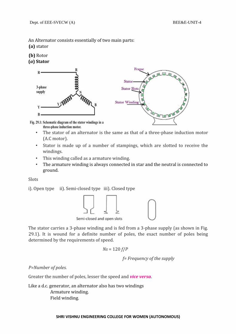
Slots
i). Open type ii). Semi-closed type iii). Closed type
The stator carries a 3-phase winding and is fed from a 3-phase supply (as shown in Fig.
29.1). It is wound for a definite number of poles, the exact number of poles being
determined by the requirements of speed.
Ns = 120 f/P
f= Frequency of the supply
P=Number of poles.
Greater the number of poles, lesser the speed and vice versa.
Like a d.c. generator, an alternator also has two windings
Armature winding.
Field winding.

Dept. of EEE-SVECW (A) BEE&E-UNIT-4
SHRI VISHNU ENGINEERING COLLEGE FOR WOMEN (AUTONOMOUS)
In alternator armature winding is placed on stator and field winding is placed on the rotor. So no commutator is required in an alternator.
(b) Rotor
Rotor construction is of two types, namely;
(i) Salient (or projecting) pole type
(ii) Non-salient (or cylindrical) pole type
The rotor carries a field winding which is supplied with direct current through two slip rings by a separate d.c. source.
(i) Salient pole type
• In this type, salient or projecting poles are mounted on a large circular steel.
• The individual field pole windings are connected in series in such a way that when the field winding is energized by the d.c. exciter, adjacent poles have opposite polarities.
• Salient pole type alternators are Low and medium-speed alternators (120-400 r.p.m.)
• Since a frequency of 50 Hz is required, we must use a large number of poles on the rotor of.
• Salient-pole type rotors have large diameters and short axial lengths. Reasons
for designing to low speed :
(a) The salient field poles would cause an excessive windage loss if driven at high speed and would tend to produce noise.
(b) Salient-pole construction cannot be made strong enough to withstand the mechanical stresses.

Dept. of EEE-SVECW (A) BEE&E-UNIT-4
SHRI VISHNU ENGINEERING COLLEGE FOR WOMEN (AUTONOMOUS)
(ii) Non-salient pole type
• In this type, the rotor is made of smooth solid forged-steel radial cylinder having
a number of slots along the outer periphery.
• The field windings are embedded in these slots and are connected in series to the slip rings through which they are energized by the d.c. exciter.
• It is clear that the poles formed are non-salient i.e., they do not project out from the rotor surface.
• Cylindrical pole type alternators are Low and medium-speed alternators (15003000 r.p.m.) Because:
(a) This type of construction has mechanical robustness and gives noiseless operation at high speeds.
(b) The flux distribution around the periphery is nearly a sine wave and hence a better e.m.f. waveform is obtained than in the case of salient-pole type.
Working of Alternators (Synchronous generator):

Dept. of EEE-SVECW (A) BEE&E-UNIT-4
SHRI VISHNU ENGINEERING COLLEGE FOR WOMEN (AUTONOMOUS)
An alternator operates on the same fundamental principle of electromagnetic induction as a d.c. generator i.e., when the flux linking a conductor changes, an e.m.f. is induced in the conductor.
The rotor winding is energized from the d.c. exciter and alternate N and S poles are developed on the rotor. When the rotor is rotated in anti-clockwise direction by a prime mover, the stator or armature conductors are cut by the magnetic flux of rotor poles. Consequently, e.m.f. is induced in the armature conductors due to electromagnetic induction. The direction of induced e.m.f. can be found by Fleming’s right hand rule and frequency is given by;
120 𝑓
Synchronous speed 𝑁𝑠 =
𝑃
P = number of rotor poles.
f= frequency of induced e.m.f in Hz.
The magnitude of the voltage induced in each phase depends upon
The rotor flux,
The number of conductors in the phase and Position of the conductors in the phase The speed of the rotor.
Induced em.f. per phase
E= 4.44 Kp Kd Φ f T
Kp= pitch factor
Kd= Distribution factor Φ= Flux per pole f= frequency T= Number of turns Kp and Kd ~=0.95

Dept. of EEE-SVECW (A) BEE&E-UNIT-4
SHRI VISHNU ENGINEERING COLLEGE FOR WOMEN (AUTONOMOUS)
E.M.F. Equation of an Alternator
Induced em.f. per phase
E= 4.44 Kp Kd Φ f T
Kp= pitch factor
Kd= Distribution factor Φ= Flux per pole f= frequency

Dept. of EEE-SVECW (A) BEE&E-UNIT-4
SHRI VISHNU ENGINEERING COLLEGE FOR WOMEN (AUTONOMOUS)
T= Number of turns Kp and Kd ~=0.95
Voltage Regulation
The voltage regulation of an alternator is defined as the change in terminal voltage from
no-load to full-load (the speed and field excitation being constant) divided by full-load
voltage
The factors affecting the voltage regulation of an alternator are:
(i) IaRa drop in armature winding
(ii) IaXL drop in armature winding
(iii) Voltage change due to armature reaction
Determination of Voltage Regulation
There are several indirect methods of determining the voltage regulation of an alternator.
These methods require only a small amount of power as compared to the power required
for direct loading method. Two such methods are:
1. Synchronous impedance or E.M.F. method
2. Ampere-turn or M.M.F. method
For either method, the following data are required:

Dept. of EEE-SVECW (A) BEE&E-UNIT-4
SHRI VISHNU ENGINEERING COLLEGE FOR WOMEN (AUTONOMOUS)
(i) Armature resistance
(ii) Open-circuit characteristic (O.C.C.)
(iii) Short-Circuit characteristic (S.C.C.)
Synchronous Impedance Method
In this method of finding the voltage regulation of an alternator, we find the synchronous
impedance Zs (and hence synchronous reactance Xs) of the alternator from the O.C.C. and
S.S.C. For this reason, it is called synchronous impedance method.
The method involves the following steps:
(i) Plot the O.C.C. and S.S.C. on the same field current base as shown in Fig. (10.24).
(ii) Consider a field current If.
The open-circuit voltage corresponding to this field current is E1.
The short-circuit armature current corresponding to field current If is I1
(iii) Once we know Ra and Xs, the phasor diagram can be drawn for any load and any
p.f. Fig. (10.26) shows the phasor diagram for the usual case of inductive load;

Dept. of EEE-SVECW (A) BEE&E-UNIT-4
SHRI VISHNU ENGINEERING COLLEGE FOR WOMEN (AUTONOMOUS)
---------------------------------------------