Embed Size (px)
Citation preview

Residential Generator SetsCommercial Generator Sets
Models:
15/30RES/RESL15/30RYG
Controllers:Advanced Digital Control ADC 2100
TP-6437 3/15d
Wiring Diagrams

TP-6437 3/15 3Introduction
Introduction
This manual provides wiring diagrams for the model15/30RES/RESL and 15/30RYG generator setsequipped with the Advanced Digital Control(ADC 2100).
Information in this publication represents data availableat the time of print. Kohler Co. reserves the right tochange this publication and the products representedwithout notice and without any obligation or liabilitywhatsoever.
Service Assistance
For professional advice on generator set powerrequirements and conscientious service, pleasecontact your nearest Kohler distributor or dealer.
D Consult the Yellow Pages under the headingGenerators—Electric.
D Visit the Kohler Power Systems website atKOHLERPower.com.
D Lookat the labels and stickers on yourKohler productor review the appropriate literature or documentsincluded with the product.
D Call toll free in the US and Canada 1-800-544-2444.
D Outside theUSandCanada, call the nearest regionaloffice.
Headquarters Europe, Middle East, Africa(EMEA)Kohler Power Systems Netherlands B.V.Kristallaan 14761 ZC ZevenbergenThe NetherlandsPhone: (31) 168 331630Fax: (31) 168 331631
Asia PacificPower Systems Asia Pacific Regional OfficeSingapore, Republic of SingaporePhone: (65) 6264-6422Fax: (65) 6264-6455
ChinaNorth China Regional Office, BeijingPhone: (86) 10 6518 7950
(86) 10 6518 7951(86) 10 6518 7952
Fax: (86) 10 6518 7955
East China Regional Office, ShanghaiPhone: (86) 21 6288 0500Fax: (86) 21 6288 0550
India, Bangladesh, Sri LankaIndia Regional OfficeBangalore, IndiaPhone: (91) 80 3366208
(91) 80 3366231Fax: (91) 80 3315972
Japan, KoreaNorth Asia Regional OfficeTokyo, JapanPhone: (813) 3440-4515Fax: (813) 3440-2727
Latin AmericaLatin America Regional OfficeLakeland, Florida, USAPhone: (863) 619-7568Fax: (863) 701-7131
TP-6437 3/154 Introduction
Wiring Diagrams
Use the Wiring Diagram Cross-Reference chart todetermine the wiring diagram version number for agiven model number and spec number. Then find thatversion number on theWiring DiagramReference chartto determine the wiring diagram numbers for your unit.
GM39949B-P
1
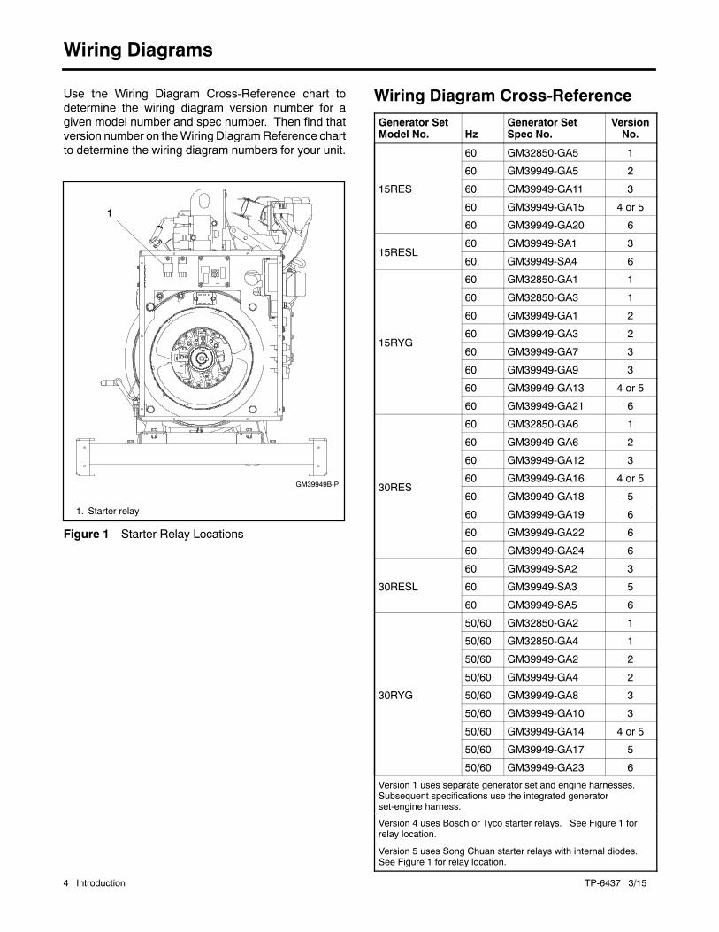
1. Starter relay
Figure 1 Starter Relay Locations
Wiring Diagram Cross-Reference
Generator SetModel No. Hz
Generator SetSpec No.
VersionNo.
15RES
60 GM32850-GA5 1
60 GM39949-GA5 2
60 GM39949-GA11 3
60 GM39949-GA15 4 or 5
60 GM39949-GA20 6
15RESL60 GM39949-SA1 3
60 GM39949-SA4 6
15RYG
60 GM32850-GA1 1
60 GM32850-GA3 1
60 GM39949-GA1 2
60 GM39949-GA3 2
60 GM39949-GA7 3
60 GM39949-GA9 3
60 GM39949-GA13 4 or 5
60 GM39949-GA21 6
30RES
60 GM32850-GA6 1
60 GM39949-GA6 2
60 GM39949-GA12 3
60 GM39949-GA16 4 or 5
60 GM39949-GA18 5
60 GM39949-GA19 6
60 GM39949-GA22 6
60 GM39949-GA24 6
30RESL
60 GM39949-SA2 3
60 GM39949-SA3 5
60 GM39949-SA5 6
30RYG
50/60 GM32850-GA2 1
50/60 GM32850-GA4 1
50/60 GM39949-GA2 2
50/60 GM39949-GA4 2
50/60 GM39949-GA8 3
50/60 GM39949-GA10 3
50/60 GM39949-GA14 4 or 5
50/60 GM39949-GA17 5
50/60 GM39949-GA23 6
Version 1 uses separate generator set and engine harnesses.Subsequent specifications use the integrated generatorset-engine harness.
Version 4 uses Bosch or Tyco starter relays. See Figure 1 forrelay location.
Version 5 uses Song Chuan starter relays with internal diodes.See Figure 1 for relay location.
TP-6437 3/15 Introduction 5
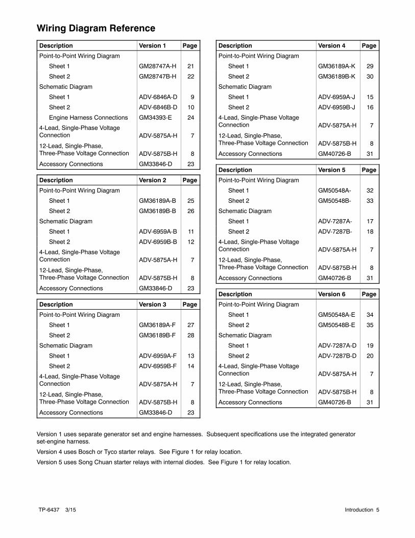
Wiring Diagram Reference
Description Version 1 Page
Point-to-Point Wiring Diagram
Sheet 1 GM28747A-H 21
Sheet 2 GM28747B-H 22
Schematic Diagram
Sheet 1 ADV-6846A-D 9
Sheet 2 ADV-6846B-D 10
Engine Harness Connections GM34393-E 24
4-Lead, Single-Phase VoltageConnection ADV-5875A-H 7
12-Lead, Single-Phase,Three-Phase Voltage Connection ADV-5875B-H 8
Accessory Connections GM33846-D 23
Description Version 2 Page
Point-to-Point Wiring Diagram
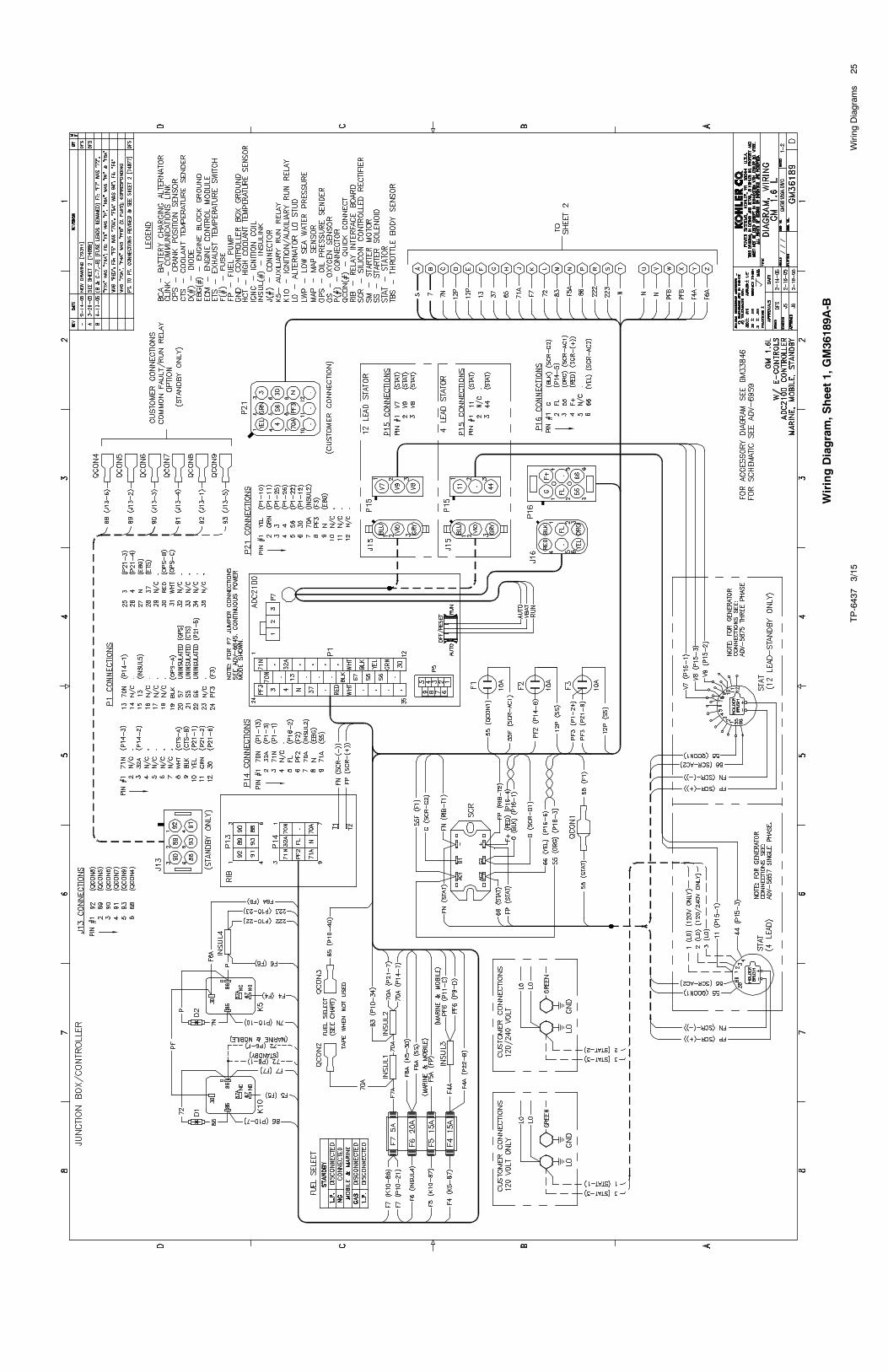
Sheet 1 GM36189A-B 25
Sheet 2 GM36189B-B 26
Schematic Diagram
Sheet 1 ADV-6959A-B 11
Sheet 2 ADV-6959B-B 12
4-Lead, Single-Phase VoltageConnection ADV-5875A-H 7
12-Lead, Single-Phase,Three-Phase Voltage Connection ADV-5875B-H 8
Accessory Connections GM33846-D 23
Description Version 3 Page
Point-to-Point Wiring Diagram
Sheet 1 GM36189A-F 27
Sheet 2 GM36189B-F 28
Schematic Diagram
Sheet 1 ADV-6959A-F 13
Sheet 2 ADV-6959B-F 14
4-Lead, Single-Phase VoltageConnection ADV-5875A-H 7
12-Lead, Single-Phase,Three-Phase Voltage Connection ADV-5875B-H 8
Accessory Connections GM33846-D 23
Description Version 4 Page
Point-to-Point Wiring Diagram
Sheet 1 GM36189A-K 29
Sheet 2 GM36189B-K 30
Schematic Diagram
Sheet 1 ADV-6959A-J 15
Sheet 2 ADV-6959B-J 16
4-Lead, Single-Phase VoltageConnection ADV-5875A-H 7
12-Lead, Single-Phase,Three-Phase Voltage Connection ADV-5875B-H 8
Accessory Connections GM40726-B 31
Description Version 5 Page
Point-to-Point Wiring Diagram
Sheet 1 GM50548A- 32
Sheet 2 GM50548B- 33
Schematic Diagram
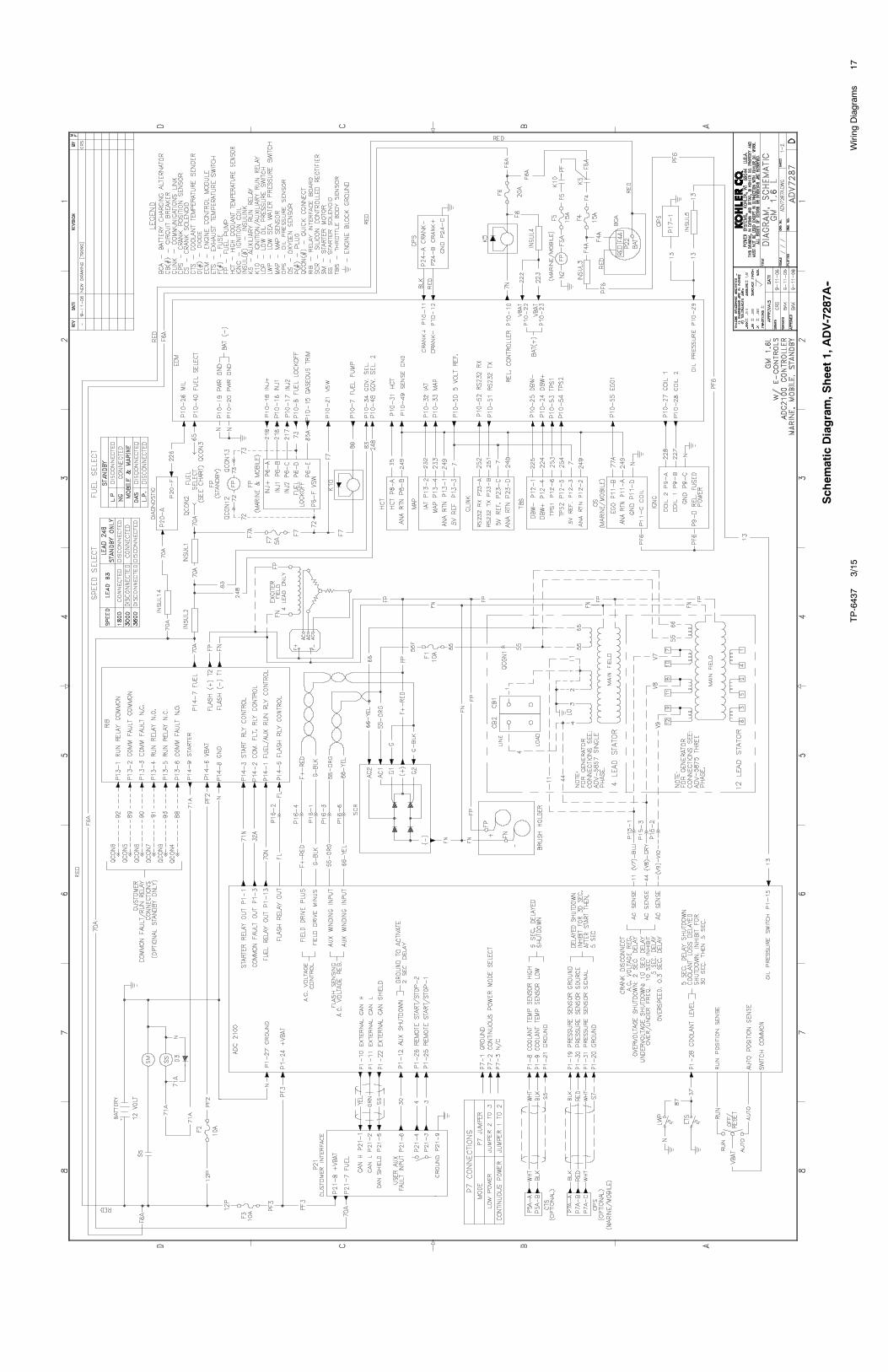
Sheet 1 ADV-7287A- 17
Sheet 2 ADV-7287B- 18
4-Lead, Single-Phase VoltageConnection ADV-5875A-H 7
12-Lead, Single-Phase,Three-Phase Voltage Connection ADV-5875B-H 8
Accessory Connections GM40726-B 31
Description Version 6 Page
Point-to-Point Wiring Diagram
Sheet 1 GM50548A-E 34
Sheet 2 GM50548B-E 35
Schematic Diagram
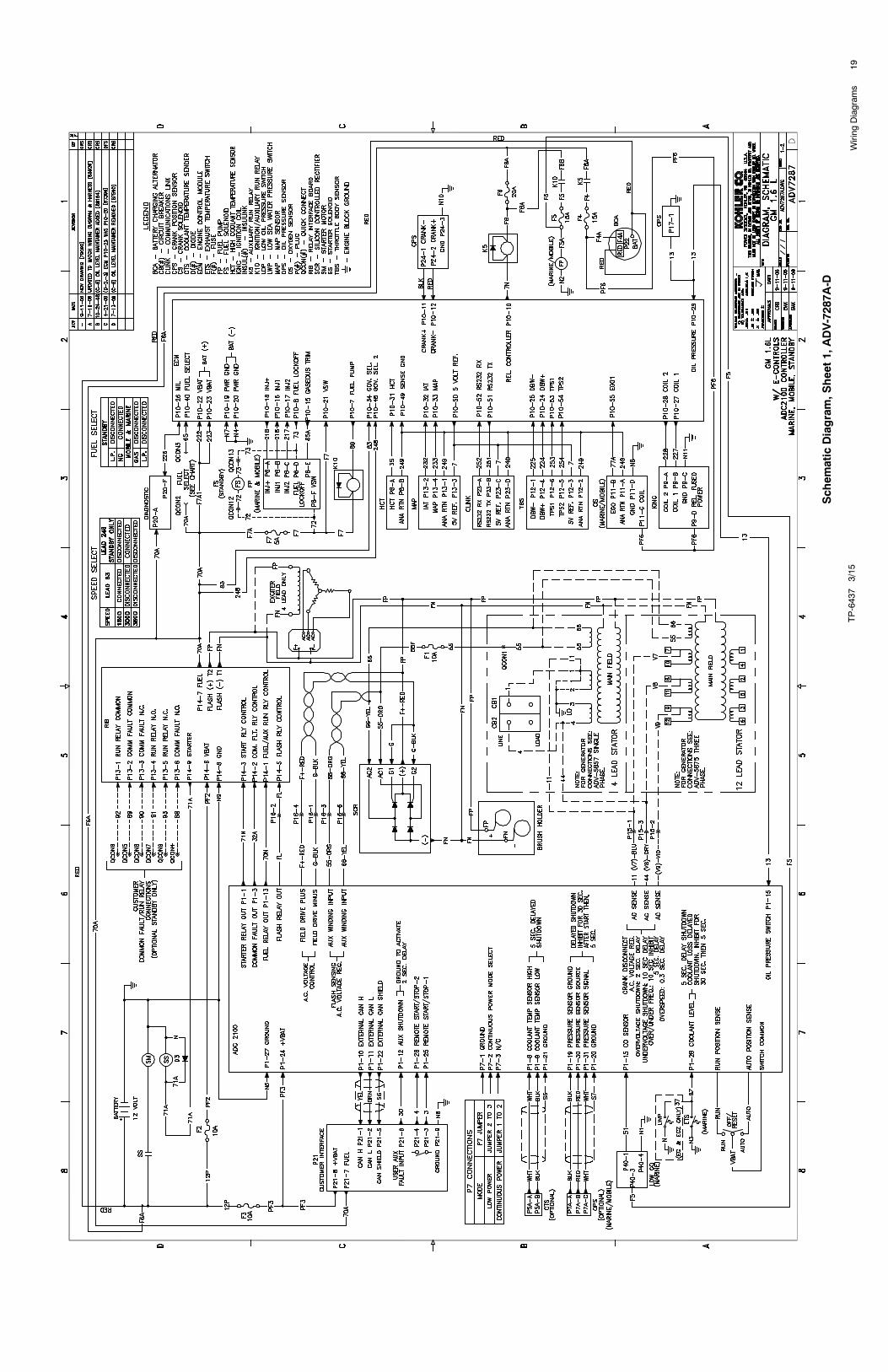
Sheet 1 ADV-7287A-D 19
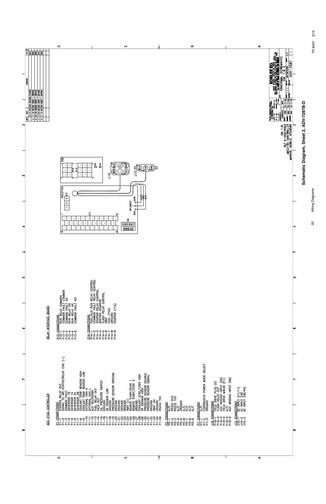
Sheet 2 ADV-7287B-D 20
4-Lead, Single-Phase VoltageConnection ADV-5875A-H 7
12-Lead, Single-Phase,Three-Phase Voltage Connection ADV-5875B-H 8
Accessory Connections GM40726-B 31
Version 1 uses separate generator set and engine harnesses. Subsequent specifications use the integrated generatorset-engine harness.
Version 4 uses Bosch or Tyco starter relays. See Figure 1 for relay location.
Version 5 uses Song Chuan starter relays with internal diodes. See Figure 1 for relay location.

TP-6437 3/156 Introduction
Notes

7Wiring
Diagram
sTP-6437
3/15
VoltageConnectionDiagram,S
ingle-Phase,ADV-5875A
-H

TP-6437
3/15
8Wiring
Diagram
s
VoltageConnectionDiagram,S
ingle-Phase,Three-Phase,ADV-5875B
-H
TP-6437
3/15
9Wiring
Diagram
s
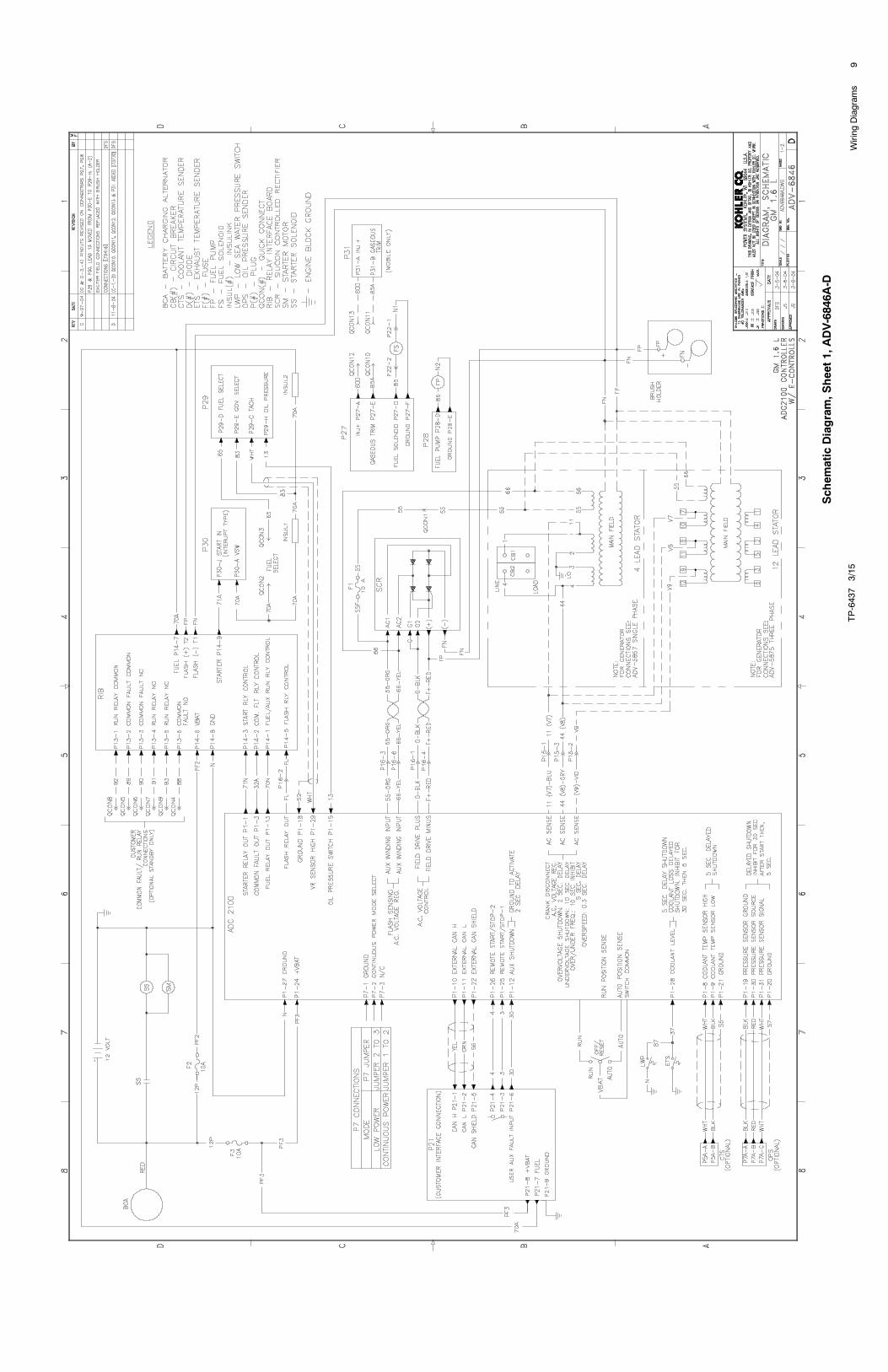
Schem
aticDiagram,S
heet1,ADV-6846A
-D

10Wiring
Diagram
sTP-6437
3/15
Schem
aticDiagram,S
heet2,ADV-6846B
-D
11Wiring
Diagram
sTP-6437
3/15
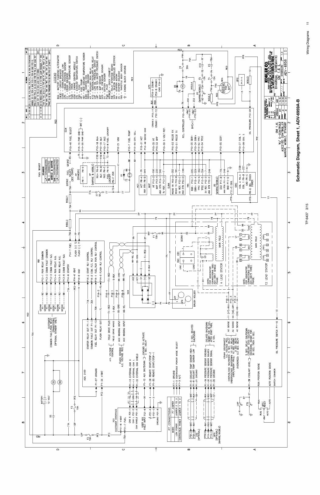
Schem
aticDiagram,S
heet1,ADV-6959A
-B

12Wiring
Diagram
sTP-6437
3/15
Schem
aticDiagram,S
heet2,ADV-6959B
-B

13Wiring
Diagram
sTP-6437
3/15
Schem
aticDiagram,S
heet1,ADV-6959A
-F
14Wiring
Diagram
sTP-6437
3/15
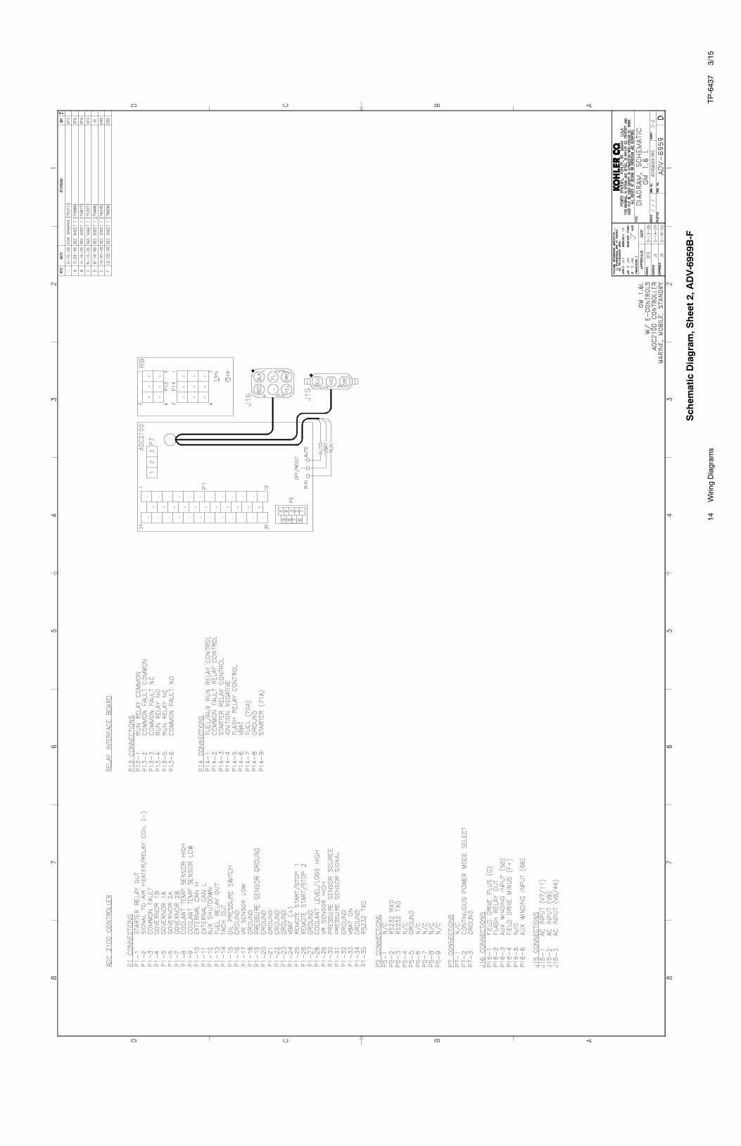
Schem
aticDiagram,S
heet2,ADV-6959B
-F

15Wiring
Diagram
sTP-6437
3/15
Schem
aticDiagram,S
heet1,ADV-6959A
-J

16Wiring
Diagram
sTP-6437
3/15
Schem
aticDiagram,S
heet2,ADV-6959B
-J
17TP-6437
3/15
Wiring
Diagram
s
Schem
aticDiagram,S
heet1,ADV-7287A
--

18TP-6437
3/15
Wiring
Diagram
s
Schem
aticDiagram,S
heet2,ADV-7287B
-
19Wiring
Diagram
sTP-6437
3/15
Schem
aticDiagram,S
heet1,ADV-7287A
-D
20TP-6437
3/15
Wiring
Diagram
s
Schem
aticDiagram,S
heet2,ADV-7287B
-D
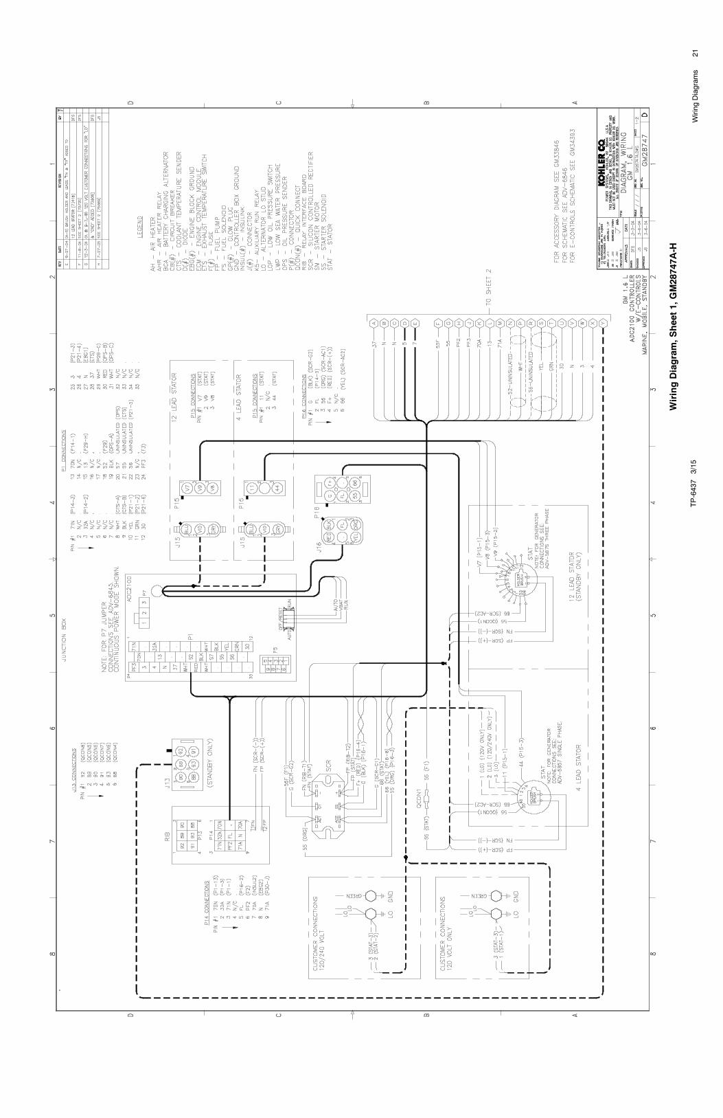
21Wiring
Diagram
sTP-6437
3/15
WiringDiagram,S
heet1,GM28747A
-H

22Wiring
Diagram
sTP-6437
3/15
WiringDiagram,S
heet2,GM28747B
-H
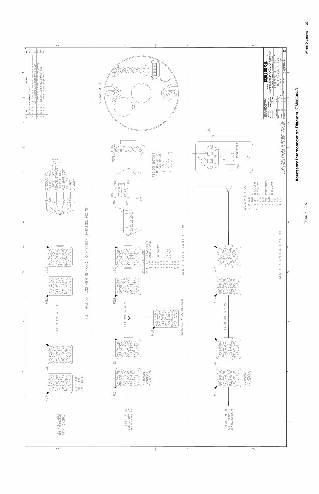
23Wiring
Diagram
sTP-6437
3/15
Accessory
InterconnectionDiagram,G
M33846-D
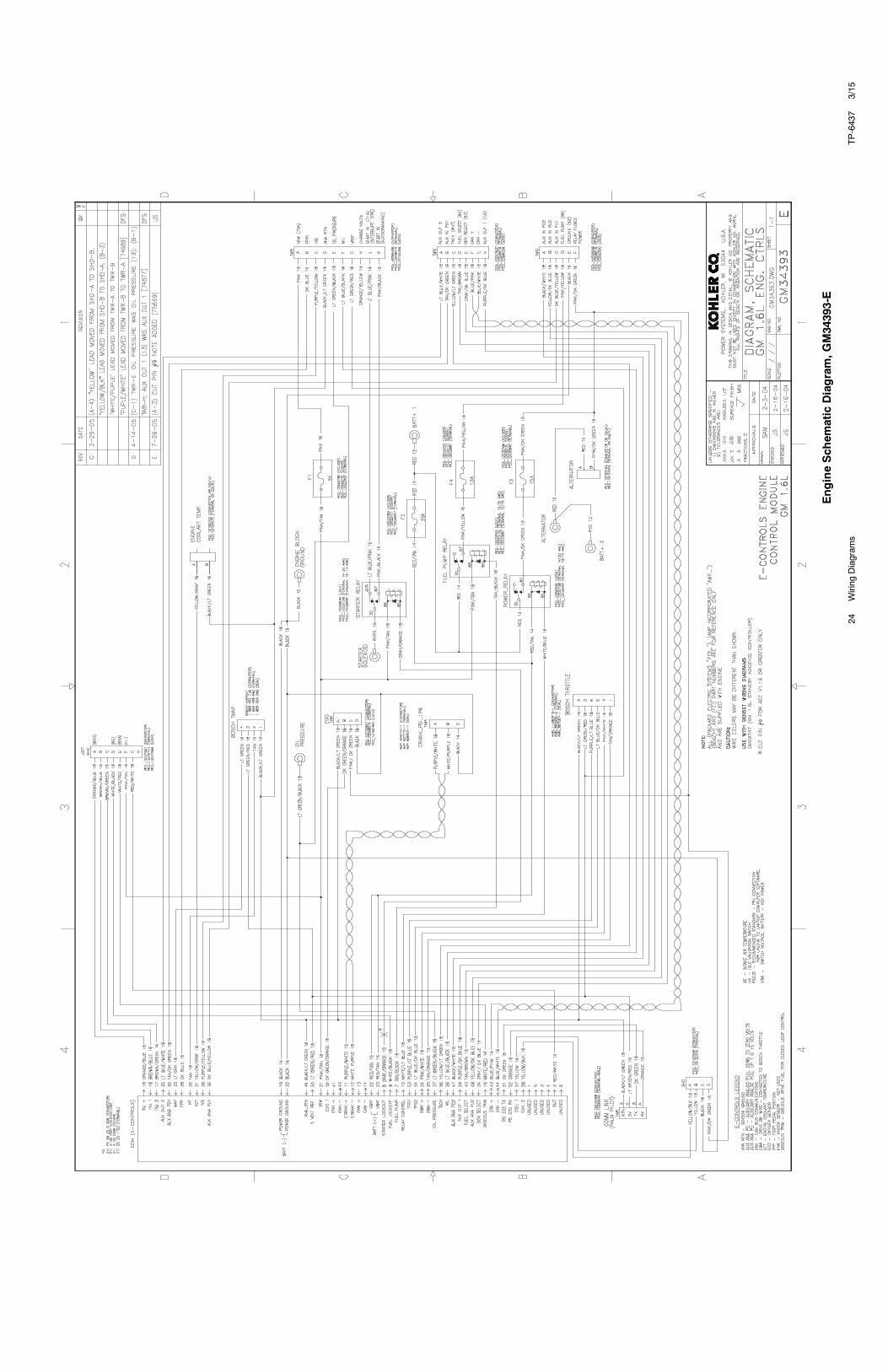
24TP-6437
3/15
Wiring
Diagram
s
EngineSchem
aticDiagram,G
M34393-E
TP-6437
3/15
25Wiring
Diagram
s
WiringDiagram,S
heet1,GM36189A
-B

26TP-6437
3/15
Wiring
Diagram
s
WiringDiagram,S
heet2,GM36189B
-B

27TP-6437
3/15
Wiring
Diagram
s
WiringDiagram,S
heet1,GM36189A
-F
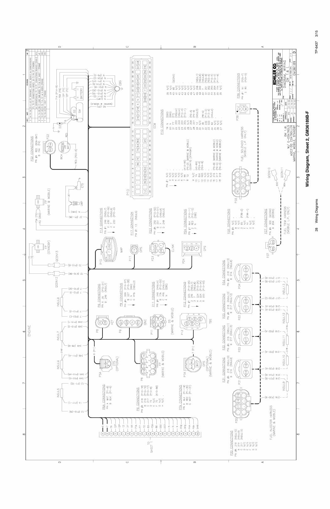
28TP-6437
3/15
Wiring
Diagram
s
WiringDiagram,S
heet2,GM36189B
-F

29TP-6437
3/15
Wiring
Diagram
s
WiringDiagram,S
heet1,GM36189A
-K
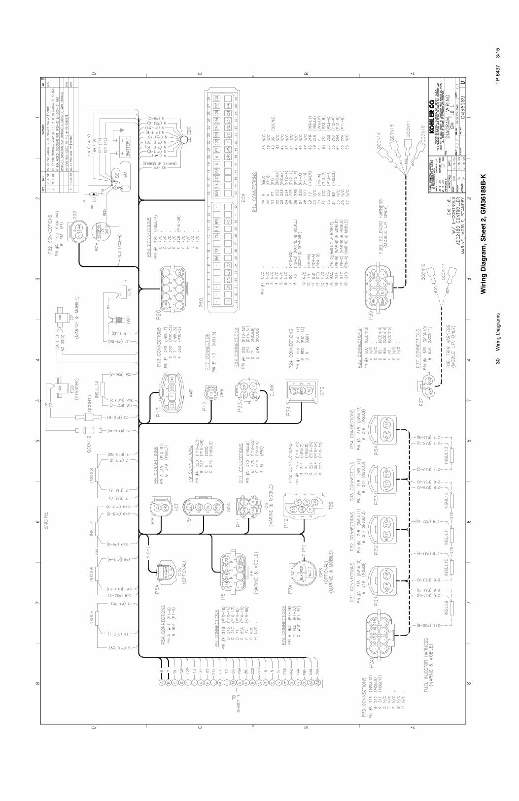
30TP-6437
3/15
Wiring
Diagram
s
WiringDiagram,S
heet2,GM36189B
-K
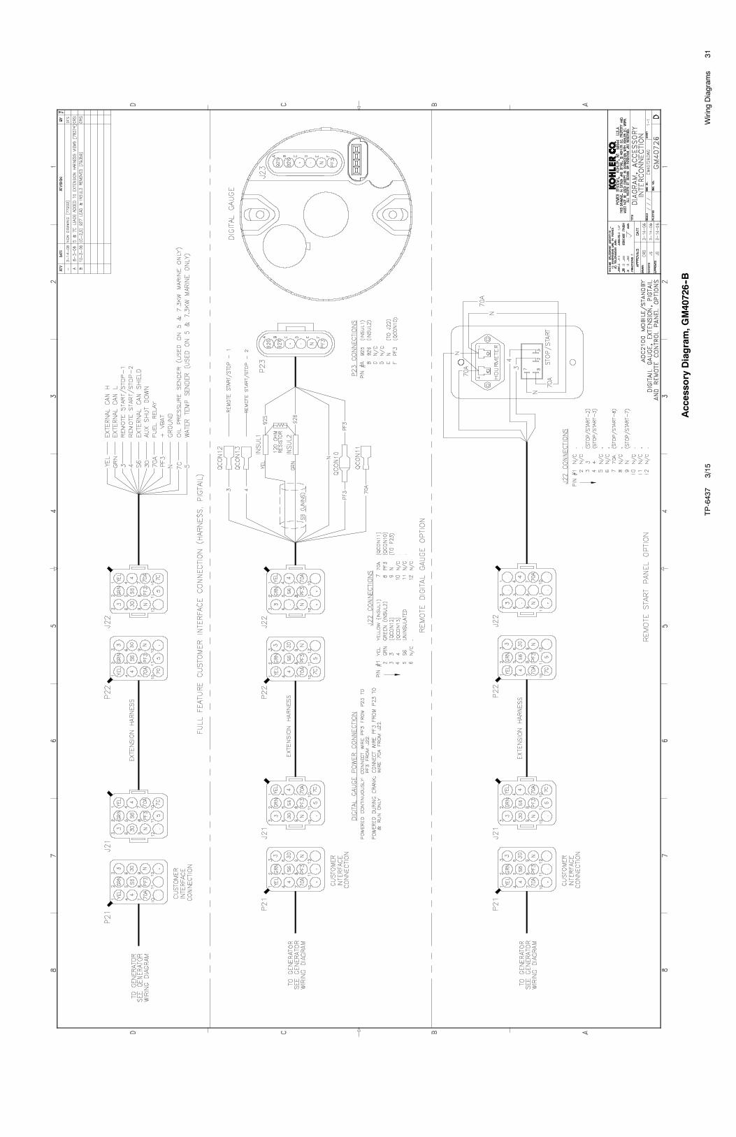
31TP-6437
3/15
Wiring
Diagram
s
Accessory
Diagram,G
M40726--B
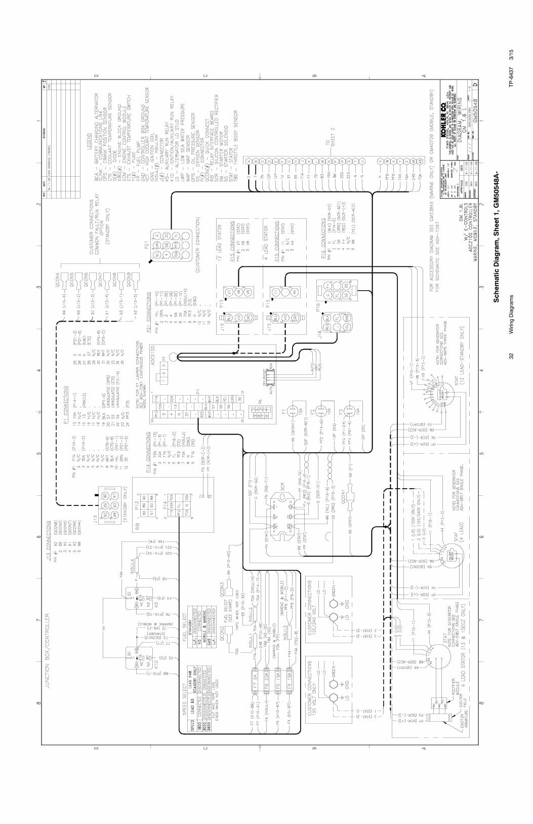
32TP-6437
3/15
Wiring
Diagram
s
Schem
aticDiagram,S
heet1,GM50548A
-
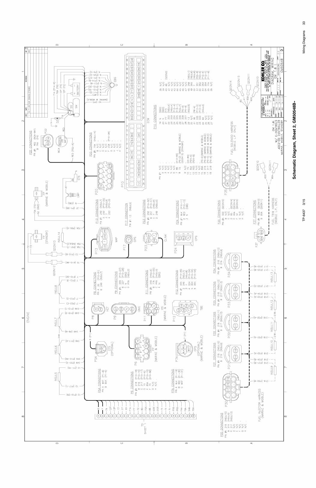
33TP-6437
3/15
Wiring
Diagram
s
Schem
aticDiagram,S
heet2,GM50548B
--

34TP-6437
3/15
Wiring
Diagram
s
Schem
aticDiagram,S
heet1,GM50548-E

35TP-6437
3/15
Wiring
Diagram
s
Schem
aticDiagram,S
heet2,GM50548-E

TP-6437
3/15
36Wiring
Diagram
s
Notes


KOHLER CO. Kohler, Wisconsin 53044Phone 920-457-4441, Fax 920-459-1646
Kohler Power SystemsAsia Pacific Headquarters7 Jurong Pier RoadSingapore 619159Phone (65) 6264-6422, Fax (65) 6264-6455
For the nearest KOHLER authorizedinstallation, service, and sales dealer inthe US and Canada:Call 1-800-544-2444 or visitKOHLERPower.comE 2006, 2007, 2008, 2015 by Kohler Co. All rights reserved.
TP-6437 3/15d