Embed Size (px)
Citation preview

LAN-1
LAN SYSTEM
K ELECTRICAL
CONTENTS
C
D
E
F
G
H
I
J
L
M
SECTION LANA
B
LAN
Revision: September 2006 2007 Frontier
CAN FUNDAMENTAL
PRECAUTIONS .......................................................... 3Precautions When Using CONSULT-II ..................... 3Precautions for Trouble Diagnosis ........................... 3Precautions for Harness Repair ............................... 3
SYSTEM DESCRIPTION ............................................ 4CAN Communication System ................................... 4
SYSTEM DIAGRAM .............................................. 4CAN COMMUNICATION CONTROL CIRCUIT ..... 5
Diag on CAN ............................................................ 6DESCRIPTION ...................................................... 6SYSTEM DIAGRAM .............................................. 6
TROUBLE DIAGNOSIS .............................................. 7Condition of Error Detection ..................................... 7
CAN COMMUNICATION SYSTEM ERROR ......... 7WHEN INDICATED “U1000” OR “U1001” IS INDI-CATED EVEN THOUGH CAN COMMUNICA-TION SYSTEM IS NORMAL ................................. 7
Symptom When Error Occurs in CAN Communi-cation System ........................................................... 8
ERROR EXAMPLE ............................................... 8Self-Diagnosis ........................................................ 12CAN Diagnostic Support Monitor ........................... 13
MONITOR ITEM (CONSULT-II) .......................... 13MONITOR ITEM (ON-BOARD DIAGNOSIS) ...... 14
TROUBLE DIAGNOSES WORK FLOW .................. 15Information Needed for Trouble Diagnosis ............. 15How to Use CAN Communication Signal Chart ..... 15Trouble Diagnosis Flow Chart ................................ 16Trouble Diagnosis Procedure ................................. 17
INTERVIEW WITH CUSTOMER ......................... 17INSPECTION OF VEHICLE CONDITION ........... 18CHECK OF CAN SYSTEM TYPE (HOW TO USE CAN SYSTEM TYPE SPECIFICATION CHART) ... 19CREATE INTERVIEW SHEET ............................ 21CREATE DATA SHEET ....................................... 22CREATE DIAGNOSIS SHEET ............................ 24DETECT THE ROOT CAUSE ............................. 25
CAN
INDEX FOR DTC ....................................................... 40DTC No. Index ........................................................ 40
HOW TO USE THIS SECTION ................................. 41Caution ................................................................... 41Abbreviation List ..................................................... 41
PRECAUTIONS ........................................................ 42Precautions for Supplemental Restraint System (SRS) “AIR BAG” and “SEAT BELT PRE-TEN-SIONER” ................................................................. 42Precautions When Using CONSULT-II ................... 42Precautions for Trouble Diagnosis ......................... 42Precautions for Harness Repair ............................. 42
TROUBLE DIAGNOSIS ............................................ 44CAN Diagnostic Support Monitor ............................ 44
MONITOR ITEM LIST (CONSULT-II) .................. 44CAN System Specification Chart ............................ 48
VEHICLE EQUIPMENT IDENTIFICATION INFORMATION .................................................... 48
CAN Communication Signal Chart ......................... 50TYPE 1/TYPE 3 ................................................... 50TYPE 2/TYPE 5 ................................................... 51TYPE 4 ................................................................ 52TYPE 6/TYPE 7 ................................................... 53TYPE 8 ................................................................ 54TYPE 9/TYPE 10 ................................................. 56TYPE 11 .............................................................. 57TYPE 12/TYPE 13 ............................................... 58TYPE 14/TYPE 15 ............................................... 60
Schematic ............................................................... 62Wiring Diagram — CAN — ..................................... 63Interview Sheet ....................................................... 66Data Sheet .............................................................. 67
CONSULT-II DATA ATTACHMENT SHEET ........ 67CAN System (Type 1) ............................................. 70
DIAGNOSIS SHEET ........................................... 70CAN System (Type 2) ............................................. 71
DIAGNOSIS SHEET ........................................... 71CAN System (Type 3) ............................................. 72
DIAGNOSIS SHEET ........................................... 72

LAN-2Revision: September 2006 2007 Frontier
CAN System (Type 4) ............................................. 73DIAGNOSIS SHEET ............................................ 73
CAN System (Type 5) ............................................. 74DIAGNOSIS SHEET ............................................ 74
CAN System (Type 6) ............................................. 75DIAGNOSIS SHEET ............................................ 75
CAN System (Type 7) ............................................. 76DIAGNOSIS SHEET ............................................ 76
CAN System (Type 8) ............................................. 77DIAGNOSIS SHEET ............................................ 77
CAN System (Type 9) ............................................. 78DIAGNOSIS SHEET ............................................ 78
CAN System (Type 10) ........................................... 79DIAGNOSIS SHEET ............................................ 79
CAN System (Type 11) ........................................... 80DIAGNOSIS SHEET ............................................ 80
CAN System (Type 12) ........................................... 81DIAGNOSIS SHEET ............................................ 81
CAN System (Type 13) ........................................... 82DIAGNOSIS SHEET ............................................ 82
CAN System (Type 14) ........................................... 83DIAGNOSIS SHEET ............................................ 83
CAN System (Type 15) ........................................... 84
DIAGNOSIS SHEET ............................................84Component Parts Location .....................................85Harness Layout .......................................................85Malfunction Area Chart ...........................................86
MAIN LINE ...........................................................86BRANCH LINE .....................................................86SHORT CIRCUIT .................................................86
Main Line Between TCM and Data Link Connector ...87Main Line Between Data Link Connector and ABS Actuator and Electric Unit .......................................88ECM Branch Line Circuit .........................................89TCM Branch Line Circuit .........................................90Transfer Control Unit Branch Line Circuit ...............90BCM Branch Line Circuit .........................................91Differential Lock Control Unit Branch Line Circuit ...92Data Link Connector Branch Line Circuit ................92Combination Meter Branch Line Circuit ..................93Steering Angle Sensor Branch Line Circuit .............94ABS Actuator and Electric Unit (Control Unit) Branch Line Circuit ..............................................................94IPDM E/R Branch Line Circuit .................................95CAN Communication Circuit ...................................96
PRECAUTIONS
LAN-3
[CAN FUNDAMENTAL]
C
D
E
F
G
H
I
J
L
M
A
B
LAN
Revision: September 2006 2007 Frontier
PRECAUTIONS PFP:00001
Precautions When Using CONSULT-II UKS006DT
Use CONSULT-II CONVERTER when connecting CONSULT-II to data link connector.CAUTION:CAN communication does not function properly if CONSULT-II is used without connecting CONSULT-IICONVERTER.
Precautions for Trouble Diagnosis UKS006DU
CAUTION: Never apply 7.0 V or more to the measurement terminal. Use a tester with open terminal voltage of 7.0 V or less. Turn the ignition switch OFF and disconnect the battery cable from the negative terminal when
checking the harness.
Precautions for Harness Repair UKS006DV
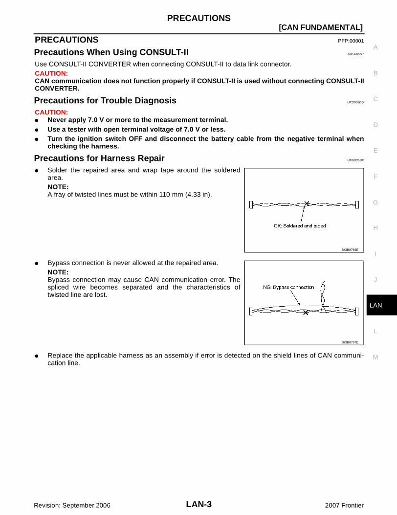
Solder the repaired area and wrap tape around the solderedarea.NOTE:A fray of twisted lines must be within 110 mm (4.33 in).
Bypass connection is never allowed at the repaired area.NOTE:Bypass connection may cause CAN communication error. Thespliced wire becomes separated and the characteristics oftwisted line are lost.
Replace the applicable harness as an assembly if error is detected on the shield lines of CAN communi-cation line.
SKIB8766E
SKIB8767E

LAN-4
[CAN FUNDAMENTAL]SYSTEM DESCRIPTION
Revision: September 2006 2007 Frontier
SYSTEM DESCRIPTION PFP:00000
CAN Communication System UKS006DW
CAN communication is a multiplex communication system. This enables the system to transmit andreceive large quantities of data at high speed by connecting control units with two communication lines(CAN-H and CAN-L).
Control units on the CAN network transmit signals using the CAN communication control circuit. Theyreceive only necessary signals from other control units to operate various functions.
CAN communication lines adopt twisted-pair line style (two lines twisted) for noise immunity.
SYSTEM DIAGRAM
Each control unit passes an electric current to the termination circuits when transmitting CAN communicationsignal. The termination circuits produce an electrical potential difference between CAN-H and CAN-L. CANcommunication system transmits and receives CAN communication signals by the potential difference.
SKIB8887E
Component Description
Main line CAN communication line between splices
Branch line CAN communication line between splice and a control unit
Splice A point connecting a branch line with a main line
Termination circuit Refer to LAN-5, "CAN COMMUNICATION CONTROL CIRCUIT" .
SYSTEM DESCRIPTION
LAN-5
[CAN FUNDAMENTAL]
C
D
E
F
G
H
I
J
L
M
A
B
LAN
Revision: September 2006 2007 Frontier
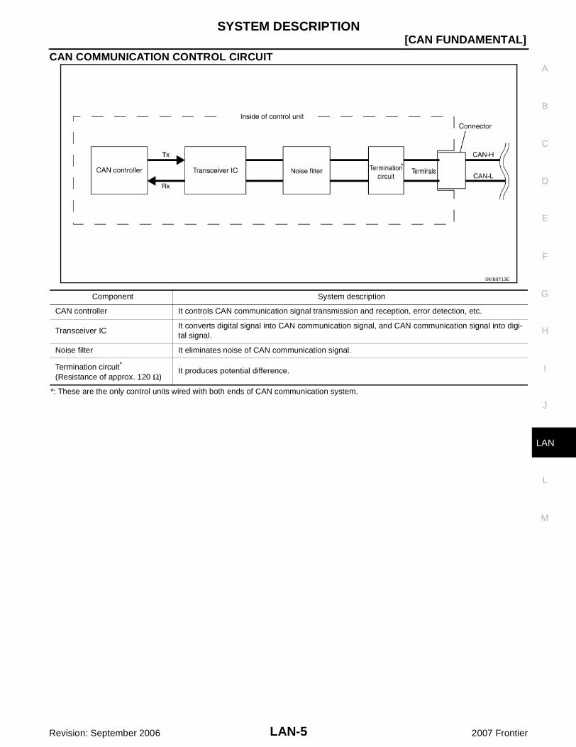
CAN COMMUNICATION CONTROL CIRCUIT
*: These are the only control units wired with both ends of CAN communication system.
SKIB8713E
Component System description
CAN controller It controls CAN communication signal transmission and reception, error detection, etc.
Transceiver ICIt converts digital signal into CAN communication signal, and CAN communication signal into digi-tal signal.
Noise filter It eliminates noise of CAN communication signal.
Termination circuit*
(Resistance of approx. 120 Ω)It produces potential difference.

LAN-6
[CAN FUNDAMENTAL]SYSTEM DESCRIPTION
Revision: September 2006 2007 Frontier
Diag on CAN UKS006DX
DESCRIPTION“Diag on CAN” is a diagnosis using CAN communication instead of previous DDL1 and DDL2 communicationline, between control unit and diagnosis unit.
SYSTEM DIAGRAM
SKIB8714E
Name Harness Description
DDL1TxRx
It is used for trouble diagnosis. (CAN-H and CAN-L are used for controlling)
DDL2 K-LINE It is used for trouble diagnosis. (CAN-H and CAN-L are used for controlling)
Diag on CANCAN-HCAN-L
It is used for trouble diagnosis and control.

TROUBLE DIAGNOSIS
LAN-7
[CAN FUNDAMENTAL]
C
D
E
F
G
H
I
J
L
M
A
B
LAN
Revision: September 2006 2007 Frontier
TROUBLE DIAGNOSIS PFP:00004
Condition of Error Detection UKS006DY
“U1000” or “U1001” is indicated on SELF-DIAG RESULTS on CONSULT-II if CAN communication signal is nottransmitted or received between units for 2 seconds or more.
CAN COMMUNICATION SYSTEM ERROR CAN communication line open (CAN-H, CAN-L, or both) CAN communication line short (ground, between CAN communication lines, other harnesses) Error of CAN communication control circuit of the unit connected to CAN communication line
WHEN INDICATED “U1000” OR “U1001” IS INDICATED EVEN THOUGH CAN COMMUNICA-TION SYSTEM IS NORMAL CONSULT-II CONVERTER not connected: Error may be detected by the self-diagnosis when not using
CONSULT-II CONVERTER (Depending on the control unit which carries out CAN communication). Removal/installation of parts: Error may be detected when removing and installing CAN communication
unit and related parts while turning the ignition switch ON. (A DTC except for CAN communication may bedetected.)
Fuse blown out (removed): CAN communication of the unit may cease. Voltage drop: Error may be detected if voltage drops due to discharged battery when turning the ignition
switch ON (Depending on the control unit which carries out CAN communication). Error may be detected if the power supply circuit of the control unit, which carries out CAN communica-
tion, malfunctions (Depending on the control unit which carries out CAN communication). Error may be detected if reprogramming is not completed normally.NOTE:CAN communication system is normal if “U1000” or “U1001” is indicated on SELF-DIAG RESULTS of CON-SULT-II under the above conditions. Erase the memory of the self-diagnosis of each unit.
LAN-8
[CAN FUNDAMENTAL]TROUBLE DIAGNOSIS
Revision: September 2006 2007 Frontier
Symptom When Error Occurs in CAN Communication System UKS006DZ
In CAN communication system, multiple units mutually transmit and receive signals. Each unit cannot transmitand receive signals if any error occurs on CAN communication line. Under this condition, multiple control unitsrelated to the root cause malfunction or go into fail-safe mode.
ERROR EXAMPLENOTE: Each vehicle differs in symptom of each unit under fail-safe mode and CAN communication line wiring. Refer to LAN-41, "Abbreviation List" for the unit abbreviation.
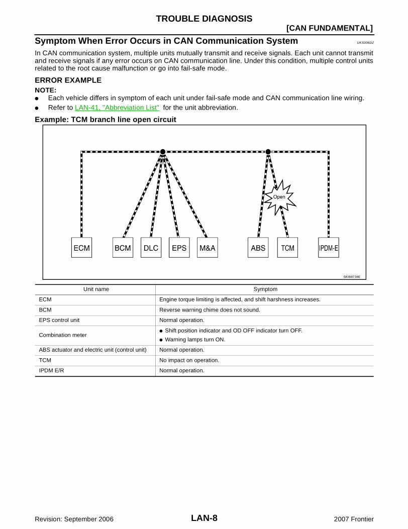
Example: TCM branch line open circuit
SKIB8738E
Unit name Symptom
ECM Engine torque limiting is affected, and shift harshness increases.
BCM Reverse warning chime does not sound.
EPS control unit Normal operation.
Combination meter Shift position indicator and OD OFF indicator turn OFF.
Warning lamps turn ON.
ABS actuator and electric unit (control unit) Normal operation.
TCM No impact on operation.
IPDM E/R Normal operation.
TROUBLE DIAGNOSIS
LAN-9
[CAN FUNDAMENTAL]
C
D
E
F
G
H
I
J
L
M
A
B
LAN
Revision: September 2006 2007 Frontier
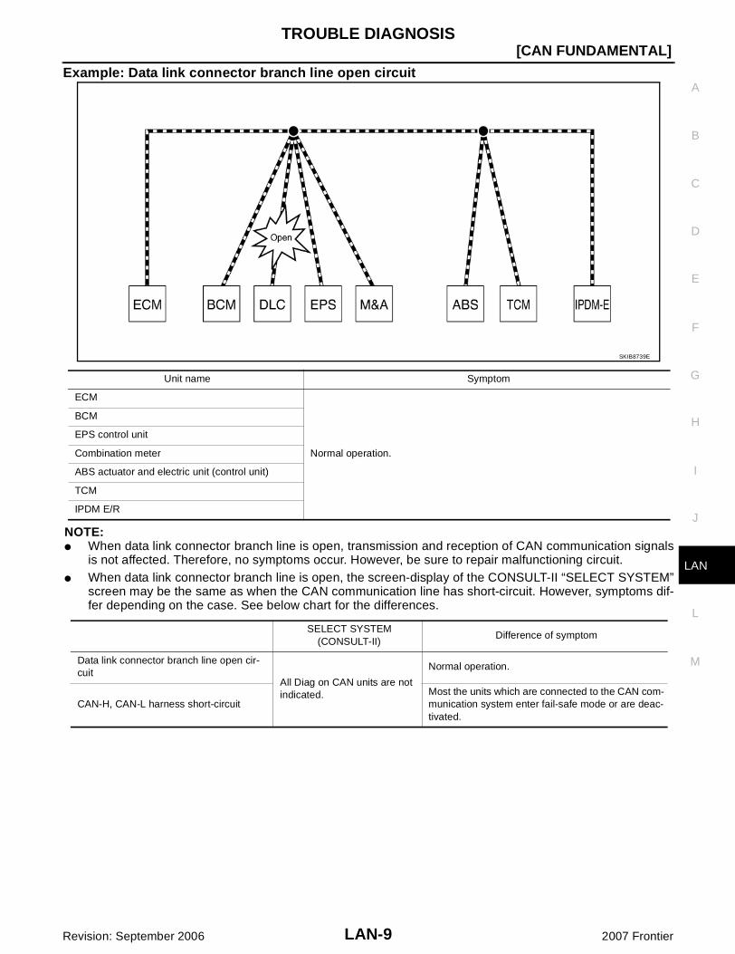
Example: Data link connector branch line open circuit
NOTE: When data link connector branch line is open, transmission and reception of CAN communication signals
is not affected. Therefore, no symptoms occur. However, be sure to repair malfunctioning circuit. When data link connector branch line is open, the screen-display of the CONSULT-II “SELECT SYSTEM”
screen may be the same as when the CAN communication line has short-circuit. However, symptoms dif-fer depending on the case. See below chart for the differences.
SKIB8739E
Unit name Symptom
ECM
Normal operation.
BCM
EPS control unit
Combination meter
ABS actuator and electric unit (control unit)
TCM
IPDM E/R
SELECT SYSTEM(CONSULT-II)
Difference of symptom
Data link connector branch line open cir-cuit
All Diag on CAN units are not indicated.
Normal operation.
CAN-H, CAN-L harness short-circuitMost the units which are connected to the CAN com-munication system enter fail-safe mode or are deac-tivated.

LAN-10
[CAN FUNDAMENTAL]TROUBLE DIAGNOSIS
Revision: September 2006 2007 Frontier
Example: Main Line Between Data Link Connector and ABS Actuator and Electric Unit (Con-trol Unit) Open Circuit
SKIB8740E
Unit name Symptom
ECM Engine torque limiting is affected, and shift harshness increases.
BCM Reverse warning chime does not sound.
The front wiper moves under continuous operation mode even though the front wiper switch being in the intermittent position.
EPS control unit The steering effort increases.
Combination meter
The shift position indicator and OD OFF indicator turn OFF.
The speedometer is inoperative.
The odo/trip meter stops.
ABS actuator and electric unit (control unit) Normal operation.
TCM No impact on operation.
IPDM E/R
When the ignition switch is ON,
The headlamps (Lo) turn ON.
The cooling fan continues to rotate.

TROUBLE DIAGNOSIS
LAN-11
[CAN FUNDAMENTAL]
C
D
E
F
G
H
I
J
L
M
A
B
LAN
Revision: September 2006 2007 Frontier
Example: CAN-H, CAN-L Harness Short Circuit
SKIB8741E
Unit name Symptom
ECM Engine torque limiting is affected, and shift harshness increases.
Engine speed drops.
BCM
Reverse warning chime does not sound.
The front wiper moves under continuous operation mode even though the front wiper switch being in the intermittent position.
The room lamp does not turn ON.
The engine does not start (if an error or malfunction occurs while turning the igni-tion switch is OFF.)
The steering lock does not release (if an error or malfunction occurs while turning the ignition switch is OFF.)
EPS control unit The steering effort increases.
Combination meter
The tachometer and the speedometer do not move.
Warning lamps turn ON.
Indicator lamps do not turn ON.
ABS actuator and electric unit (control unit) Normal operation.
TCM No impact on operation.
IPDM E/R
When the ignition switch is ON,
The headlamps (Lo) turn ON.
The cooling fan continues to rotate.

LAN-12
[CAN FUNDAMENTAL]TROUBLE DIAGNOSIS
Revision: September 2006 2007 Frontier
Self-Diagnosis UKS006E0
DTCSelf-diagnosis item
(CONSULT-II indication)DTC detection condition Inspection/Action
U1000 CAN COMM CIRCUIT
When ECM is not transmitting or receiving CAN communication signal of OBD (emission-related diagnosis) for 2 seconds or more.
Refer to LAN-15, "TROUBLE DIAG-NOSES WORK FLOW" .
When a control unit (except for ECM) is not transmitting or receiving CAN communication signal for 2 seconds or more.
U1001 CAN COMM CIRCUITWhen ECM is not transmitting or receiving CAN communication signal other than OBD (emis-sion-related diagnosis) for 2 seconds or more.
U1002 SYSTEM COMMWhen a control unit is not transmitting or receiv-ing CAN communication signal for 2 seconds or less.
Start the inspection. Refer to the applicable section of the indicated control unit.
U1010 CONTROL UNIT [CAN]When an error is detected during the initial diag-nosis for CAN controller of each control unit.
Replace the control unit indicating “U1010”.
TROUBLE DIAGNOSIS
LAN-13
[CAN FUNDAMENTAL]
C
D
E
F
G
H
I
J
L
M
A
B
LAN
Revision: September 2006 2007 Frontier
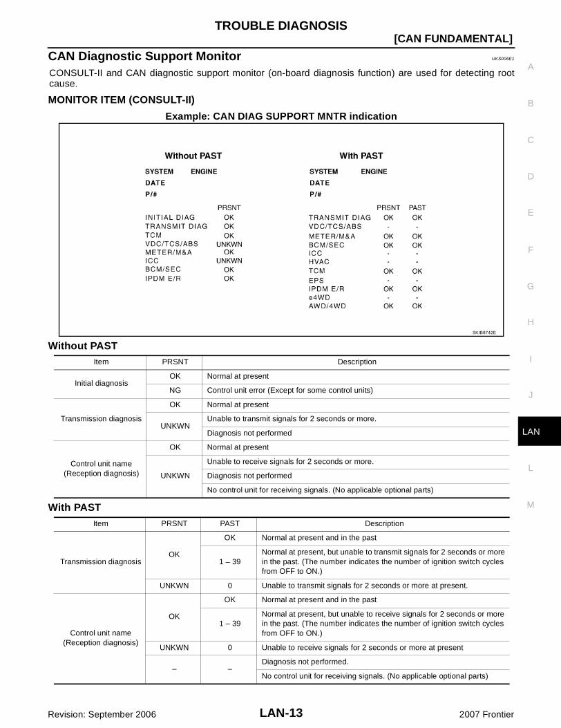
CAN Diagnostic Support Monitor UKS006E1
CONSULT-II and CAN diagnostic support monitor (on-board diagnosis function) are used for detecting rootcause.
MONITOR ITEM (CONSULT-II)
Example: CAN DIAG SUPPORT MNTR indication
Without PAST
With PAST
SKIB8742E
Item PRSNT Description
Initial diagnosisOK Normal at present
NG Control unit error (Except for some control units)
Transmission diagnosis
OK Normal at present
UNKWNUnable to transmit signals for 2 seconds or more.
Diagnosis not performed
Control unit name(Reception diagnosis)
OK Normal at present
UNKWN
Unable to receive signals for 2 seconds or more.
Diagnosis not performed
No control unit for receiving signals. (No applicable optional parts)
Item PRSNT PAST Description
Transmission diagnosisOK
OK Normal at present and in the past
1 – 39Normal at present, but unable to transmit signals for 2 seconds or more in the past. (The number indicates the number of ignition switch cycles from OFF to ON.)
UNKWN 0 Unable to transmit signals for 2 seconds or more at present.
Control unit name(Reception diagnosis)
OK
OK Normal at present and in the past
1 – 39Normal at present, but unable to receive signals for 2 seconds or more in the past. (The number indicates the number of ignition switch cycles from OFF to ON.)
UNKWN 0 Unable to receive signals for 2 seconds or more at present
– –Diagnosis not performed.
No control unit for receiving signals. (No applicable optional parts)
LAN-14
[CAN FUNDAMENTAL]TROUBLE DIAGNOSIS
Revision: September 2006 2007 Frontier
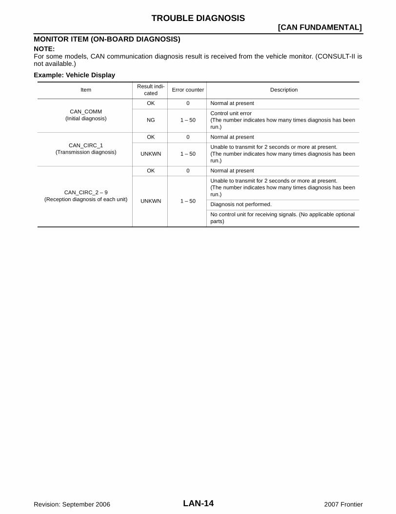
MONITOR ITEM (ON-BOARD DIAGNOSIS)NOTE:For some models, CAN communication diagnosis result is received from the vehicle monitor. (CONSULT-II isnot available.)
Example: Vehicle Display
ItemResult indi-
catedError counter Description
CAN_COMM(Initial diagnosis)
OK 0 Normal at present
NG 1 – 50Control unit error(The number indicates how many times diagnosis has been run.)
CAN_CIRC_1(Transmission diagnosis)
OK 0 Normal at present
UNKWN 1 – 50Unable to transmit for 2 seconds or more at present.(The number indicates how many times diagnosis has been run.)
CAN_CIRC_2 – 9(Reception diagnosis of each unit)
OK 0 Normal at present
UNKWN 1 – 50
Unable to transmit for 2 seconds or more at present.(The number indicates how many times diagnosis has been run.)
Diagnosis not performed.
No control unit for receiving signals. (No applicable optional parts)

TROUBLE DIAGNOSES WORK FLOW
LAN-15
[CAN FUNDAMENTAL]
C
D
E
F
G
H
I
J
L
M
A
B
LAN
Revision: September 2006 2007 Frontier
TROUBLE DIAGNOSES WORK FLOW PFP:00004
Information Needed for Trouble Diagnosis UKS006E2
CAN communication system performs trouble diagnosis with the following tools.
How to Use CAN Communication Signal Chart UKS006E3
The CAN communication signal chart lists the signals needed for trouble diagnosis. It is useful for detectingthe root cause by finding a signal related to the symptom, and by checking transmission and reception unit.
Tool Usage
Interview sheet For filling in vehicle information and interview with customer.
Data sheet For attaching CONSULT-II data or on-board diagnosis data.
Diagnosis sheetFor detecting the root cause. (Diagnosis sheet includes system diagram for every CAN system type)
SELECT SYSTEM(CONSULT-II)
For checking the condition of control units and the status of CAN communication.SELF-DIAG RESULTS(CONSULT-II)
CAN DIAG SUPPORT MNTR(CONSULT-II)
CAN communication signal chart
For converting information received from a customer into CAN communication signal transmission and reception. This information can be used to judge whether a circuit between control units is nor-mal or abnormal.
Abbreviation list For checking abbreviations in CAN communication signal chart and diagnosis sheet.
SKIB8715E
LAN-16
[CAN FUNDAMENTAL]TROUBLE DIAGNOSES WORK FLOW
Revision: September 2006 2007 Frontier
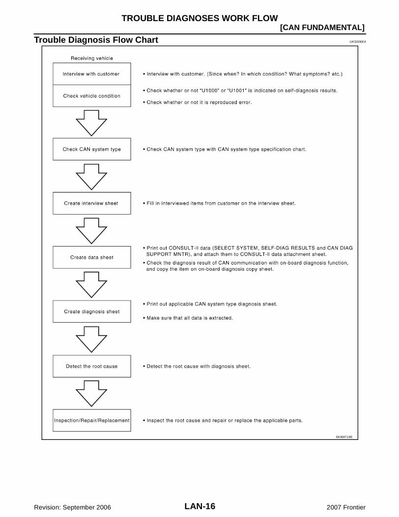
Trouble Diagnosis Flow Chart UKS006E4
SKIB8716E
TROUBLE DIAGNOSES WORK FLOW
LAN-17
[CAN FUNDAMENTAL]
C
D
E
F
G
H
I
J
L
M
A
B
LAN
Revision: September 2006 2007 Frontier
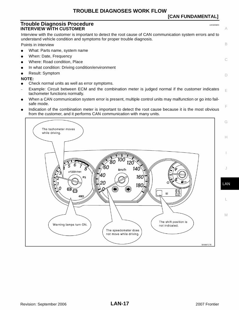
Trouble Diagnosis Procedure UKS006E5
INTERVIEW WITH CUSTOMERInterview with the customer is important to detect the root cause of CAN communication system errors and tounderstand vehicle condition and symptoms for proper trouble diagnosis.Points in interview What: Parts name, system name When: Date, Frequency Where: Road condition, Place In what condition: Driving condition/environment Result: SymptomNOTE: Check normal units as well as error symptoms.– Example: Circuit between ECM and the combination meter is judged normal if the customer indicates
tachometer functions normally. When a CAN communication system error is present, multiple control units may malfunction or go into fail-
safe mode. Indication of the combination meter is important to detect the root cause because it is the most obvious
from the customer, and it performs CAN communication with many units.
SKIB8717E

LAN-18
[CAN FUNDAMENTAL]TROUBLE DIAGNOSES WORK FLOW
Revision: September 2006 2007 Frontier
INSPECTION OF VEHICLE CONDITION Check whether or not “U1000” or “U1001” is indicated on “SELF-DIAG RESULTS” by CONSULT-II.
NOTE:Root cause cannot be detected using the procedure in this section if “U1000” or “U1001” is not indicated.
Check whether the symptom is reproduced or not.NOTE: Never turn the ignition switch OFF or disconnect the battery cable while the reproducing the error. The
error may temporarily correct itself, making it difficult to determine the root cause. The procedures for present errors differ from the procedures for past errors. Refer to LAN-25,
"DETECT THE ROOT CAUSE" .
TROUBLE DIAGNOSES WORK FLOW
LAN-19
[CAN FUNDAMENTAL]
C
D
E
F
G
H
I
J
L
M
A
B
LAN
Revision: September 2006 2007 Frontier
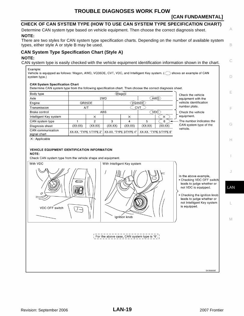
CHECK OF CAN SYSTEM TYPE (HOW TO USE CAN SYSTEM TYPE SPECIFICATION CHART)Determine CAN system type based on vehicle equipment. Then choose the correct diagnosis sheet.NOTE:There are two styles for CAN system type specification charts. Depending on the number of available systemtypes, either style A or style B may be used.
CAN System Type Specification Chart (Style A)NOTE:CAN system type is easily checked with the vehicle equipment identification information shown in the chart.
SKIB8888E

LAN-20
[CAN FUNDAMENTAL]TROUBLE DIAGNOSES WORK FLOW
Revision: September 2006 2007 Frontier
CAN System Type Specification Chart (Style B)NOTE:CAN system type is easily checked with the vehicle equipment identification information shown in the chart.
SKIB8889E

TROUBLE DIAGNOSES WORK FLOW
LAN-21
[CAN FUNDAMENTAL]
C
D
E
F
G
H
I
J
L
M
A
B
LAN
Revision: September 2006 2007 Frontier
CREATE INTERVIEW SHEETFill out the symptom described by the customer, vehicle condition, and CAN system type on the interviewsheet.
Interview Sheet (Example)
SKIB8890E
LAN-22
[CAN FUNDAMENTAL]TROUBLE DIAGNOSES WORK FLOW
Revision: September 2006 2007 Frontier
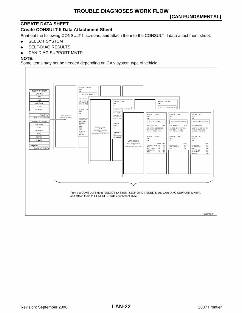
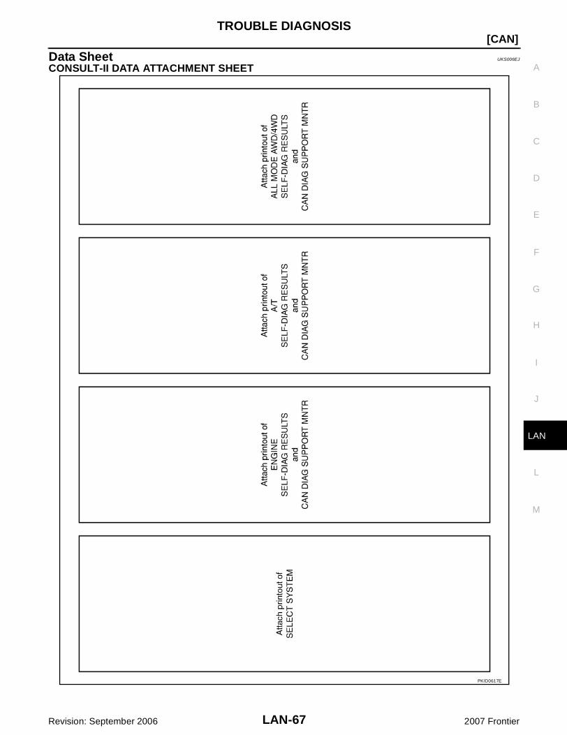
CREATE DATA SHEETCreate CONSULT-II Data Attachment SheetPrint out the following CONSULT-II screens, and attach them to the CONSULT-II data attachment sheet. SELECT SYSTEM SELF-DIAG RESULTS CAN DIAG SUPPORT MNTRNOTE:Some items may not be needed depending on CAN system type of vehicle.
SKIB8721E
TROUBLE DIAGNOSES WORK FLOW
LAN-23
[CAN FUNDAMENTAL]
C
D
E
F
G
H
I
J
L
M
A
B
LAN
Revision: September 2006 2007 Frontier
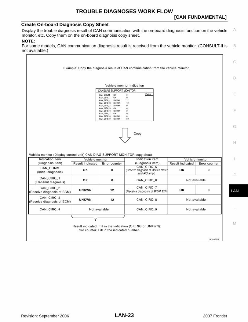
Create On-board Diagnosis Copy SheetDisplay the trouble diagnosis result of CAN communication with the on-board diagnosis function on the vehiclemonitor, etc. Copy them on the on-board diagnosis copy sheet.NOTE:For some models, CAN communication diagnosis result is received from the vehicle monitor. (CONSULT-II isnot available.)
SKIB8722E
LAN-24
[CAN FUNDAMENTAL]TROUBLE DIAGNOSES WORK FLOW
Revision: September 2006 2007 Frontier
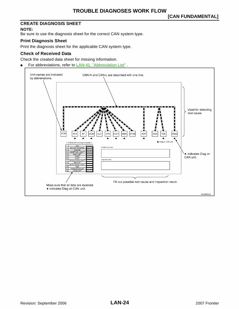
CREATE DIAGNOSIS SHEETNOTE:Be sure to use the diagnosis sheet for the correct CAN system type.
Print Diagnosis SheetPrint the diagnosis sheet for the applicable CAN system type.
Check of Received DataCheck the created data sheet for missing information. For abbreviations, refer to LAN-41, "Abbreviation List" .
SKIB8891E

TROUBLE DIAGNOSES WORK FLOW
LAN-25
[CAN FUNDAMENTAL]
C
D
E
F
G
H
I
J
L
M
A
B
LAN
Revision: September 2006 2007 Frontier
DETECT THE ROOT CAUSEIdentify the root cause using the created diagnosis sheet.Identifying the root cause Draw a line on the diagnosis sheet to indicate the possible cause. Narrow the search.
NOTE: Color-code when drawing lines. Do not draw a line onto a existing line.
Drawing a line is not necessary if the circuit is shorted. Refer to LAN-32, "Present Error — Short Circuit —" , LAN-39, "Past Error — Short Circuit —" .
Refer to the following for details of the trouble diagnosis procedure. LAN-26, "Present Error — Open Circuit —" LAN-32, "Present Error — Short Circuit —" LAN-33, "Past Error — Open Circuit —" LAN-39, "Past Error — Short Circuit —"NOTE:When the root cause appears to be a branch line or short circuit, be sure to check the control unit as well asthe communication line.

LAN-26
[CAN FUNDAMENTAL]TROUBLE DIAGNOSES WORK FLOW
Revision: September 2006 2007 Frontier
Present Error — Open Circuit —Identify the error circuit using information from the “SELECT SYSTEM” and “CAN DIAG SUPPORT MNTR”screens.1. SELECT SYSTEM: Check the items indicated in “SELECT SYSTEM”. Draw a line on the diagnosis sheet
to indicate the error circuit.NOTE:CAN communication line has no error if units other than Diag on CAN units are indicated. An error may beon the power supply of the control unit, DDL1 line or DDL2 line.
a. “TRANSMISSION” which is Diag on CAN unit, is not indicated on “SELECT SYSTEM” screen. This indi-cates that DLC is not receiving a signal from TCM. Draw a line to indicate an error between DLC and TCM(line 1-a in the figure).NOTE: Diag on CAN units are not indicated on the “SELECT SYSTEM” screen when the CAN line between
Diag on CAN unit and the data link connector is open. For a description of Diag on CAN, refer to LAN-6, "Diag on CAN" .
SKIB8892E

TROUBLE DIAGNOSES WORK FLOW
LAN-27
[CAN FUNDAMENTAL]
C
D
E
F
G
H
I
J
L
M
A
B
LAN
Revision: September 2006 2007 Frontier
2. CAN DIAG SUPPORT MNTR: Check each item on “CAN DIAG SUPPORT MNTR”. Draw a line on thediagnosis sheet to indicate the error circuit.
a. Reception item of “ENGINE”: On “TCM”, “UNKWN” is indicated. This means ECM cannot receive the sig-nal from TCM. Draw a line to indicate an error between ECM and TCM (line 2-a in the figure).NOTE:If “UNKWN” is indicated on “TRANSMIT DIAG”, then the control unit cannot transmit CAN communicationsignal to each unit. Draw a line between the control unit and the splice.
b. Reception item of “ADAPTIVE LIGHT”: On “TCM”, “UNKWN” is indicated. This means AFS cannotreceive the signal from TCM. Draw a line to indicate an error between AFS and TCM (line 2-b in the fig-ure).
c. Reception item of “MULTI AV”: “UNKWN” is not indicated. This indicates normal communication betweenAV and its receiving units. Do not draw any line.
SKIB8725E

LAN-28
[CAN FUNDAMENTAL]TROUBLE DIAGNOSES WORK FLOW
Revision: September 2006 2007 Frontier
d. Reception item of “BCM”: On “TCM”, “UNKWN” is indicated. This means BCM cannot receive the signalfrom TCM. Draw a line to indicate an error between BCM and TCM (line 2-d in the figure).
e. Reception item of “EPS” and “INTELLIGENT KEY”: “UNKWN” is not indicated. This indicates normal com-munication between EPS and I-KEY and their receiving units. Do not draw any line.NOTE:On CAN DIAG SUPPORT MNTR (without PAST), “UNKWN” is indicated even though the item is not usedin the trouble diagnosis. For the details of each item on CAN diagnostic support monitor, refer to LAN-44,"CAN Diagnostic Support Monitor" .
SKIB8726E

TROUBLE DIAGNOSES WORK FLOW
LAN-29
[CAN FUNDAMENTAL]
C
D
E
F
G
H
I
J
L
M
A
B
LAN
Revision: September 2006 2007 Frontier
f. Reception item of “METER”: On “TCM”, “UNKWN” is indicated. This means M&A cannot receive the sig-nal from TCM. Draw a line to indicate an error between M&A and TCM (line 2-f in the figure).
g. Reception item of “AUTO DRIVE POS.”: On “TCM”, “UNKWN” is indicated. This means ADP cannotreceive the signal from TCM. Draw a line to indicate an error between ADP and TCM (line 2-g in the fig-ure).
h. Reception item of “ABS”: “UNKWN” is not indicated. This indicates normal communication between ABSand its receiving units. Do not draw any line.
SKIB8727E

LAN-30
[CAN FUNDAMENTAL]TROUBLE DIAGNOSES WORK FLOW
Revision: September 2006 2007 Frontier
i. Reception item of “IPDM E/R”: “UNKWN” is not indicated. This indicates normal communication betweenIPDM-E and its receiving units. Do not draw any line.
3. Based on information received from “CAN DIAG SUPPORT MNTR”, place a check mark on the knowngood CAN communication line between ECM and IPDM-E.
a. Through the previous procedure, the circuit between ADP splice and TCM has the most amount of lines(shade 3-a in the figure).
b. Place a check mark on the known good lines to establish the error circuit.Reception item of “IPDM E/R”: On “ECM”, “OK” is indicated. IPDM-E communicates normally with ECM.Put a check mark on the normal circuit between ECM and IPDM-E (check mark 3-b in the figure).
SKIB8728E

TROUBLE DIAGNOSES WORK FLOW
LAN-31
[CAN FUNDAMENTAL]
C
D
E
F
G
H
I
J
L
M
A
B
LAN
Revision: September 2006 2007 Frontier
4. Through the above procedure, the error is detected in the TCM branch line (shaded in the figure).NOTE:For abbreviations, refer to LAN-41, "Abbreviation List" .
5. Perform the inspection for the detected error circuit. For the inspection procedure, refer to LAN-86, "Mal-function Area Chart" .
SKIB8893E

LAN-32
[CAN FUNDAMENTAL]TROUBLE DIAGNOSES WORK FLOW
Revision: September 2006 2007 Frontier
Present Error — Short Circuit —When the symptoms listed below exist, a short circuit of the CAN communication line is a possible cause.
Received data
Error symptom Most the units connected to the CAN communication system go into fail-safe mode or are deactivated.Inspection procedure Refer to LAN-86, "Malfunction Area Chart" .
Item (CONSULT-II) Indication
SELECT SYSTEM All Diag on CAN units are not indicated.
CAN DIAG SUPPORT MNTR “UNKWN” is indicated under “TRANSMIT DIAG” and most reception items.
SKIB8894E

TROUBLE DIAGNOSES WORK FLOW
LAN-33
[CAN FUNDAMENTAL]
C
D
E
F
G
H
I
J
L
M
A
B
LAN
Revision: September 2006 2007 Frontier
Past Error — Open Circuit —Review CAN communication signal chart based on information received from the interview with the customerand on past error information from SELF-DIAG RESULTS and CAN DIAG SUPPORT MNTR.1. SELF-DIAG RESULTS: Inspect the control units indicating “U1000” or “U1001” on SELF-DIAG RESULTS.
SKIB8731E

LAN-34
[CAN FUNDAMENTAL]TROUBLE DIAGNOSES WORK FLOW
Revision: September 2006 2007 Frontier
2. CAN DIAG SUPPORT MNTR (with PAST): Check the CAN DIAG SUPPORT MNTR (with PAST) of unitsindicating “U1000” or “U1001” on SELF-DIAG RESULTS. Draw a line on the diagnosis sheet to indicatethe possible error circuit.NOTE:For the details of each indication on CAN DIAG SUPPORT MNTR, refer to LAN-44, "CAN Diagnostic Sup-port Monitor" .
a. Reception item of “ENGINE”: “VDC/TCS/ABS”, “3” is indicated in the “PAST”. This means ECM could notreceive the signal from ABS in the past. Draw a line between ECM and ABS (line 2-a in the figure).
b. Reception item of “METER”: “VDC/TCS/ABS”, “3” is indicated in the “PAST”. This means M&A could notreceive the signal from ABS in the past. Draw a line between M&A and ABS (line 2-b in the figure).
c. Reception item of “TRANSMISSION”: “VDC/TCS/ABS”, “3” is indicated in the “PAST”. This means TCMcould not receive the signal from ABS in the past. Draw a line between TCM and ABS (line 2-c in the fig-ure).
SKIB8732E

TROUBLE DIAGNOSES WORK FLOW
LAN-35
[CAN FUNDAMENTAL]
C
D
E
F
G
H
I
J
L
M
A
B
LAN
Revision: September 2006 2007 Frontier
3. CAN DIAG SUPPORT MNTR (without PAST): Check the CAN DIAG SUPPORT MNTR (without PAST) ofunits indicating “U1000” or “U1001” on SELF-DIAG RESULTS. Draw a line on the diagnosis sheet to indi-cate the possible error circuit.NOTE: While an error occurred in the past according to SELF-DIAG RESULTS, it is unclear which signal is not
received. Assume that errors were detected from all reception items. Draw a single line among the unit and all reception items. (Work flow differs from CAN DIAG SUPPORT
MNTR (with PAST).)a. Reception item of “EPS”: Assume that the unit could not receive the signals from ECM, ABS, and M&A.
Draw a line among EPS, ECM, ABS, and M&A (line 3-a in the figure).b. Reception item of “ABS”: Assume that the unit could not receive the signal from ECM. Draw a line
between ABS and ECM (line 3-b in the figure).
SKIB8733E

LAN-36
[CAN FUNDAMENTAL]TROUBLE DIAGNOSES WORK FLOW
Revision: September 2006 2007 Frontier
4. Search for the possible cause using CAN communication signal chart using information from the interviewwith the customer.NOTE:For the details of CAN communication signal, refer to LAN-50, "CAN Communication Signal Chart" .
a. ABS warning lamp turned ON and speedometer did not move: This means that “ABS warning lamp signal”and “Vehicle speed signal” could not communicate between M&A and ABS (4-a in the figure).
b. The tachometer moved normally: This means that “Engine speed signal” could communicate normallybetween ECM and M&A (4-b in the figure).
SKIB8895E

TROUBLE DIAGNOSES WORK FLOW
LAN-37
[CAN FUNDAMENTAL]
C
D
E
F
G
H
I
J
L
M
A
B
LAN
Revision: September 2006 2007 Frontier
5. Fill out the diagnosis sheet based on information from step 4.a. The ABS warning lamp turned ON and speedometer did not move: Assume that a possible cause is no
communication between M&A and ABS. Draw a line between M&A and ABS. (Line 5-a in the figure).b. The tachometer moved normally: Put check marks between ECM and M&A. The circuit between ECM and
M&A is functioning properly (check marks 5-b in the figure).
SKIB8735E
LAN-38
[CAN FUNDAMENTAL]TROUBLE DIAGNOSES WORK FLOW
Revision: September 2006 2007 Frontier
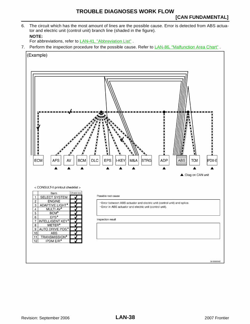
6. The circuit which has the most amount of lines are the possible cause. Error is detected from ABS actua-tor and electric unit (control unit) branch line (shaded in the figure).NOTE:For abbreviations, refer to LAN-41, "Abbreviation List" .
7. Perform the inspection procedure for the possible cause. Refer to LAN-86, "Malfunction Area Chart" .
SKIB8896E
TROUBLE DIAGNOSES WORK FLOW
LAN-39
[CAN FUNDAMENTAL]
C
D
E
F
G
H
I
J
L
M
A
B
LAN
Revision: September 2006 2007 Frontier
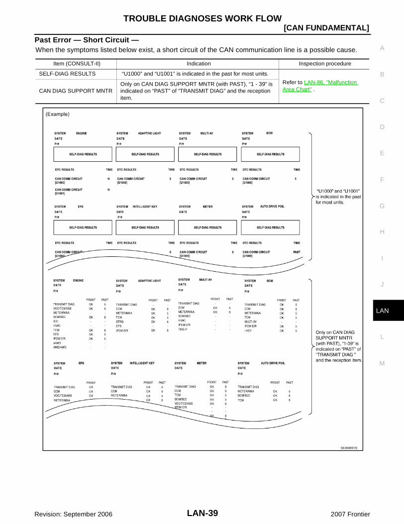
Past Error — Short Circuit —When the symptoms listed below exist, a short circuit of the CAN communication line is a possible cause.
Item (CONSULT-II) Indication Inspection procedure
SELF-DIAG RESULTS “U1000” and “U1001” is indicated in the past for most units.
Refer to LAN-86, "Malfunction Area Chart" .CAN DIAG SUPPORT MNTR
Only on CAN DIAG SUPPORT MNTR (with PAST), “1 - 39” is indicated on “PAST” of “TRANSMIT DIAG” and the reception item.
SKIB8897E

LAN-40
[CAN]INDEX FOR DTC
Revision: September 2006 2007 Frontier
INDEX FOR DTC PFP:00004
DTC No. Index UKS006E6
DTCSelf-diagnosis item
(CONSULT-II indication)DTC detection condition Inspection
U1000 CAN COMM CIRCUIT
When ECM is not transmitting or receiving CAN communication signal of OBD (emission-related diagnosis) for 2 seconds or more.
Refer to LAN-41, "HOW TO USE THIS SEC-TION" .
When a control unit (except for ECM) is not transmitting or receiving CAN communication signal for 2 seconds or more.
U1001 CAN COMM CIRCUITWhen ECM is not transmitting or receiving CAN communication signal other than OBD (emis-sion-related diagnosis) for 2 seconds or more.
U1002 SYSTEM COMMWhen a control unit is not transmitting or receiv-ing CAN communication signal for 2 seconds or less.
Start the inspection. Refer to the applicable section of the indicated control unit.
U1010 CONTROL UNIT [CAN]When an error is detected during the initial diag-nosis for CAN controller of each control unit.
Replace the control unit indicating “U1010”.
HOW TO USE THIS SECTION
LAN-41
[CAN]
C
D
E
F
G
H
I
J
L
M
A
B
LAN
Revision: September 2006 2007 Frontier
HOW TO USE THIS SECTION PFP:00008
Caution UKS006E7
This section describes information peculiar to a vehicle, sheets for trouble diagnosis, and inspection pro-cedures.
For trouble diagnosis procedure, refer to LAN-17, "Trouble Diagnosis Procedure" .
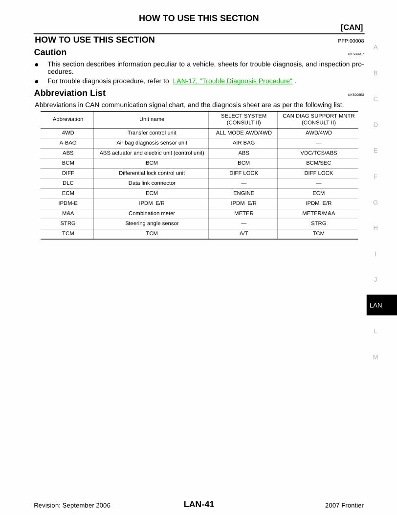
Abbreviation List UKS006E8
Abbreviations in CAN communication signal chart, and the diagnosis sheet are as per the following list.
Abbreviation Unit nameSELECT SYSTEM
(CONSULT-II)CAN DIAG SUPPORT MNTR
(CONSULT-II)
4WD Transfer control unit ALL MODE AWD/4WD AWD/4WD
A-BAG Air bag diagnosis sensor unit AIR BAG —
ABS ABS actuator and electric unit (control unit) ABS VDC/TCS/ABS
BCM BCM BCM BCM/SEC
DIFF Differential lock control unit DIFF LOCK DIFF LOCK
DLC Data link connector — —
ECM ECM ENGINE ECM
IPDM-E IPDM E/R IPDM E/R IPDM E/R
M&A Combination meter METER METER/M&A
STRG Steering angle sensor — STRG
TCM TCM A/T TCM

LAN-42
[CAN]PRECAUTIONS
Revision: September 2006 2007 Frontier
PRECAUTIONS PFP:00001
Precautions for Supplemental Restraint System (SRS) “AIR BAG” and “SEAT BELT PRE-TENSIONER” UKS006E9
The Supplemental Restraint System such as “AIR BAG” and “SEAT BELT PRE-TENSIONER”, used alongwith a front seat belt, helps to reduce the risk or severity of injury to the driver and front passenger for certaintypes of collision. This system includes seat belt switch inputs and dual stage front air bag modules. The SRSsystem uses the seat belt switches to determine the front air bag deployment, and may only deploy one frontair bag, depending on the severity of a collision and whether the front occupants are belted or unbelted.Information necessary to service the system safely is included in the SRS and SB section of this Service Man-ual.WARNING: To avoid rendering the SRS inoperative, which could increase the risk of personal injury or death
in the event of a collision which would result in air bag inflation, all maintenance must be per-formed by an authorized NISSAN/INFINITI dealer.
Improper maintenance, including incorrect removal and installation of the SRS, can lead to per-sonal injury caused by unintentional activation of the system. For removal of Spiral Cable and AirBag Module, see the SRS section.
Do not use electrical test equipment on any circuit related to the SRS unless instructed to in thisService Manual. SRS wiring harnesses can be identified by yellow and/or orange harnesses orharness connectors.
Precautions When Using CONSULT-II UKS006EA
Use CONSULT-II CONVERTER when connecting CONSULT-II to data link connector.CAUTION:CAN communication does not function properly if CONSULT-II is used without connecting CONSULT-IICONVERTER.
Precautions for Trouble Diagnosis UKS006EB
CAUTION: Never apply 7.0 V or more to the measurement terminal. Use a tester with open terminal voltage of 7.0 V or less. Turn the ignition switch OFF and disconnect the battery cable from the negative terminal when
checking the harness.
Precautions for Harness Repair UKS006EC
Solder the repaired area and wrap tape around the solderedarea.NOTE:A fray of twisted lines must be within 110 mm (4.33 in).
SKIB8766E

PRECAUTIONS
LAN-43
[CAN]
C
D
E
F
G
H
I
J
L
M
A
B
LAN
Revision: September 2006 2007 Frontier
Bypass connection is never allowed at the repaired area.NOTE:Bypass connection may cause CAN communication error. Thespliced wire becomes separated and the characteristics oftwisted line are lost.
Replace the applicable harness as an assembly if error is detected on the shield lines of CAN communi-cation line.
SKIB8767E

LAN-44
[CAN]TROUBLE DIAGNOSIS
Revision: September 2006 2007 Frontier
TROUBLE DIAGNOSIS PFP:00004
CAN Diagnostic Support Monitor UKS006ED
Use “CAN DIAG SUPPORT MNTR” for detecting the root cause.
MONITOR ITEM LIST (CONSULT-II)ECM
0: Error at present, 1 – 39: Error in the past (Number means the number of times the ignition switch is turned OFF→ON)
*: 39 or higher number is fixed at 39 until the self-diagnosis result is erased.
TCMNOTE:Replace the unit when “NG” is indicated on the “INITIAL DIAG”.
SELECT SYS-TEM
CAN DIAG SUP-PORT MNTR
DescriptionNormal Error
PRSNT PAST PRSNT PAST
ENGINE
TRANSMIT DIAG Signal transmission status OKOKor
1 – 39*UNKWN 0
VDC/TCS/ABS
With ABS: Not used even though indicated
With ABLS/VDC: Signal receiving status from the ABS actuator and electric unit (control unit)
OKOKor
1 – 39*UNKWN 0
METER/M&ASignal receiving status from the combina-tion meter
BCM/SEC Signal receiving status from the BCM
ICCNot used even though indicated
HVAC
TCM Signal receiving status from the TCM OKOKor
1 – 39*UNKWN 0
EPS Not used even though indicated
IPDM E/R Signal receiving status from the IPDM E/R OKOKor
1 – 39*UNKWN 0
e4WD Not used even though indicated
AWD/4WDSignal receiving status from the transfer control unit
OKOKor
1 – 39*UNKWN 0
SELECT SYS-TEM
CAN DIAG SUP-PORT MNTR
DescriptionNormal Error
PRSNT
A/T
INITIAL DIAG Status of CAN controller
OK
NG
TRANSMIT DIAG Signal transmission statusUNKWN
ECM Signal receiving status from the ECM
VDC/TCS/ABS
With ABS: Not used even though indicated
With ABLS/VDC: Signal receiving status from the ABS actuator and electric unit (control unit) OK UNKWN
METER/M&A Signal receiving status from the combination meter
ICC/e4WD Not used even though indicated
AWD/4WD Signal receiving status from the transfer control unit OK UNKWN

TROUBLE DIAGNOSIS
LAN-45
[CAN]
C
D
E
F
G
H
I
J
L
M
A
B
LAN
Revision: September 2006 2007 Frontier
Transfer Control UnitNOTE:Replace the unit when “NG” is indicated on the “INITIAL DIAG”.
BCMNOTE:Replace the unit when “NG” is indicated on the “INITIAL DIAG”.
Differential Lock Control UnitNOTE:Replace the unit when “NG” is indicated on the “INITIAL DIAG”.
SELECT SYS-TEM
CAN DIAG SUP-PORT MNTR
DescriptionNormal Error
PRSNT
ALL MODE AWD/4WD
INITIAL DIAG Status of CAN controller
OK
NG
TRANSMIT DIAG Signal transmission status
UNKWN
ECM Signal receiving status from the ECM
VDC/TCS/ABSSignal receiving status from the ABS actuator and electric unit (control unit)
TCM Signal receiving status from the TCM
METER/M&A Signal receiving status from the combination meter
SELECT SYS-TEM
CAN DIAG SUP-PORT MNTR
DescriptionNormal Error
PRSNT
BCM
INITIAL DIAG Status of CAN controller
OK
NG
TRANSMIT DIAG Signal transmission status
UNKWNECM Signal receiving status from the ECM
IPDM E/R Signal receiving status from the IPDM E/R
METER/M&A Signal receiving status from the combination meter
I-KEY Not used even though indicated
SELECT SYS-TEM
CAN DIAG SUP-PORT MNTR
DescriptionNormal Error
PRSNT
DIFF LOCK
INITIAL DIAG Status of CAN controller
OK
NG
TRANSMIT DIAG Signal transmission status
UNKWN
ECM Signal receiving status from the ECM
VDC/TCS/ABSSignal receiving status from the ABS actuator and electric unit (control unit)
AWD/4WD Signal receiving status from the transfer control unit
LAN-46
[CAN]TROUBLE DIAGNOSIS
Revision: September 2006 2007 Frontier
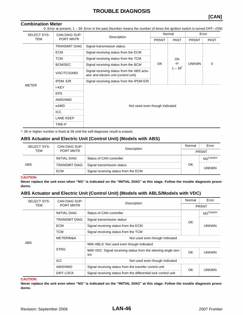
Combination Meter0: Error at present, 1 – 39: Error in the past (Number means the number of times the ignition switch is turned OFF→ON)
*: 39 or higher number is fixed at 39 until the self-diagnosis result is erased.
ABS Actuator and Electric Unit (Control Unit) (Models with ABS)
CAUTION:Never replace the unit even when “NG” is indicated on the “INITIAL DIAG” at this stage. Follow the trouble diagnosis proce-dures.
ABS Actuator and Electric Unit (Control Unit) (Models with ABLS/Models with VDC)
CAUTION:Never replace the unit even when “NG” is indicated on the “INITIAL DIAG” at this stage. Follow the trouble diagnosis proce-dures.
SELECT SYS-TEM
CAN DIAG SUP-PORT MNTR
DescriptionNormal Error
PRSNT PAST PRSNT PAST
METER
TRANSMIT DIAG Signal transmission status
OKOKor
1 – 39*UNKWN 0
ECM Signal receiving status from the ECM
TCM Signal receiving status from the TCM
BCM/SEC Signal receiving status from the BCM
VDC/TCS/ABSSignal receiving status from the ABS actu-ator and electric unit (control unit)
IPDM E/R Signal receiving status from the IPDM E/R
I-KEY
Not used even though indicated
EPS
AWD/4WD
e4WD
ICC
LANE KEEP
TIRE-P
SELECT SYS-TEM
CAN DIAG SUP-PORT MNTR
DescriptionNormal Error
PRSNT
ABS
INITIAL DIAG Status of CAN controller
OK
NGCaution
TRANSMIT DIAG Signal transmission statusUNKWN
ECM Signal receiving status from the ECM
SELECT SYS-TEM
CAN DIAG SUP-PORT MNTR
DescriptionNormal Error
PRSNT
ABS
INITIAL DIAG Status of CAN controller
OK
NGCaution
TRANSMIT DIAG Signal transmission status
UNKWNECM Signal receiving status from the ECM
TCM Signal receiving status from the TCM
METER/M&A Not used even though indicated
STRG
With ABLS: Not used even though indicated
With VDC: Signal receiving status from the steering angle sen-sor
OK UNKWN
ICC Not used even though indicated
AWD/4WD Signal receiving status from the transfer control unitOK UNKWN
DIFF LOCK Signal receiving status from the differential lock control unit

TROUBLE DIAGNOSIS
LAN-47
[CAN]
C
D
E
F
G
H
I
J
L
M
A
B
LAN
Revision: September 2006 2007 Frontier
IPDM E/R0: Error at present, 1 – 39: Error in the past (Number means the number of times the ignition switch is turned OFF→ON)
*: 39 or higher number is fixed at 39 until the self-diagnosis result is erased.
SELECT SYS-TEM
CAN DIAG SUP-PORT MNTR
DescriptionNormal Error
PRSNT PAST PRSNT PAST
IPDM E/R
TRANSMIT DIAG Signal transmission status
OKOKor
1 – 39*UNKWN 0ECM Signal receiving status from the ECM
BCM/SEC Signal receiving status from the BCM

LAN-48
[CAN]TROUBLE DIAGNOSIS
Revision: September 2006 2007 Frontier
CAN System Specification Chart UKS006EE
Determine CAN system type from the following specification chart. Then choose the correct diagnosis sheet.NOTE:Refer to LAN-19, "CHECK OF CAN SYSTEM TYPE (HOW TO USE CAN SYSTEM TYPE SPECIFICATIONCHART)" for how to use CAN system specification chart.
×: Applicable
VEHICLE EQUIPMENT IDENTIFICATION INFORMATIONNOTE:Check CAN system type from the vehicle shape and equipment. Models with ABLS
Models with VDC
Body type Truck
Axle 2WD 4WD
Engine QR25DE VQ40DE
Transmission M/T A/T M/T A/T M/T A/T
Brake control ABS ABSABL
SABS ABLS ABS ABLS ABS ABLS VDC
Electronic locking rear differential
× × × ×
CAN system type 1 2 3 4 5 6 7 8 9 10 11 12 13 14 15
Diagnosis sheetLAN-
70LAN-
71LAN-
72LAN-
73LAN-
74LAN-
75LAN-
76LAN-
77LAN-
78LAN-
79LAN-
80LAN-
81LAN-
82LAN-
83LAN-
84
CAN communica-tion signal chart
LAN-50,
"TYPE 1/TYPE 3"
LAN-51,
"TYPE 2/TYPE 5"
LAN-50,
"TYPE 1/TYPE 3"
LAN-52,
"TYPE 4"
LAN-51,
"TYPE 2/TYPE 5"
LAN-53, "TYPE 6/TYPE 7"
LAN-54,
"TYPE 8"
LAN-56, "TYPE 9/TYPE 10"
LAN-57,
"TYPE 11"
LAN-58, "TYPE 12/TYPE 13"
LAN-60, "TYPE 14/TYPE 15"
BKIA0174E
BKIA0202E

TROUBLE DIAGNOSIS
LAN-49
[CAN]
C
D
E
F
G
H
I
J
L
M
A
B
LAN
Revision: September 2006 2007 Frontier
Models with electronic locking rear differential
BKIA0203E
LAN-50
[CAN]TROUBLE DIAGNOSIS
Revision: September 2006 2007 Frontier
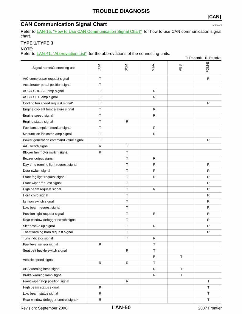
CAN Communication Signal Chart UKS006EF
Refer to LAN-15, "How to Use CAN Communication Signal Chart" for how to use CAN communication signalchart.
TYPE 1/TYPE 3NOTE:Refer to LAN-41, "Abbreviation List" for the abbreviations of the connecting units.
T: Transmit R: Receive
Signal name/Connecting unit
EC
M
BC
M
M&
A
AB
S
IPD
M-E
A/C compressor request signal T R
Accelerator pedal position signal T
ASCD CRUISE lamp signal T R
ASCD SET lamp signal T R
Cooling fan speed request signal* T R
Engine coolant temperature signal T R
Engine speed signal T R
Engine status signal T R
Fuel consumption monitor signal T R
Malfunction indicator lamp signal T R
Power generation command value signal T R
A/C switch signal R T
Blower fan motor switch signal R T
Buzzer output signal T R
Day time running light request signal T R R
Door switch signal T R R
Front fog light request signal T R R
Front wiper request signal T R
High beam request signal T R R
Horn chirp signal T R
Ignition switch signal T R
Low beam request signal T R
Position light request signal T R R
Rear window defogger switch signal T R
Sleep wake up signal T R R
Theft warning horn request signal T R
Turn indicator signal T R
Fuel level sensor signal R T
Seat belt buckle switch signal R T
Vehicle speed signalR T
R R T
ABS warning lamp signal R T
Brake warning lamp signal R T
Front wiper stop position signal R T
High beam status signal R T
Low beam status signal R T
Rear window defogger control signal* R T
TROUBLE DIAGNOSIS
LAN-51
[CAN]
C
D
E
F
G
H
I
J
L
M
A
B
LAN
Revision: September 2006 2007 Frontier
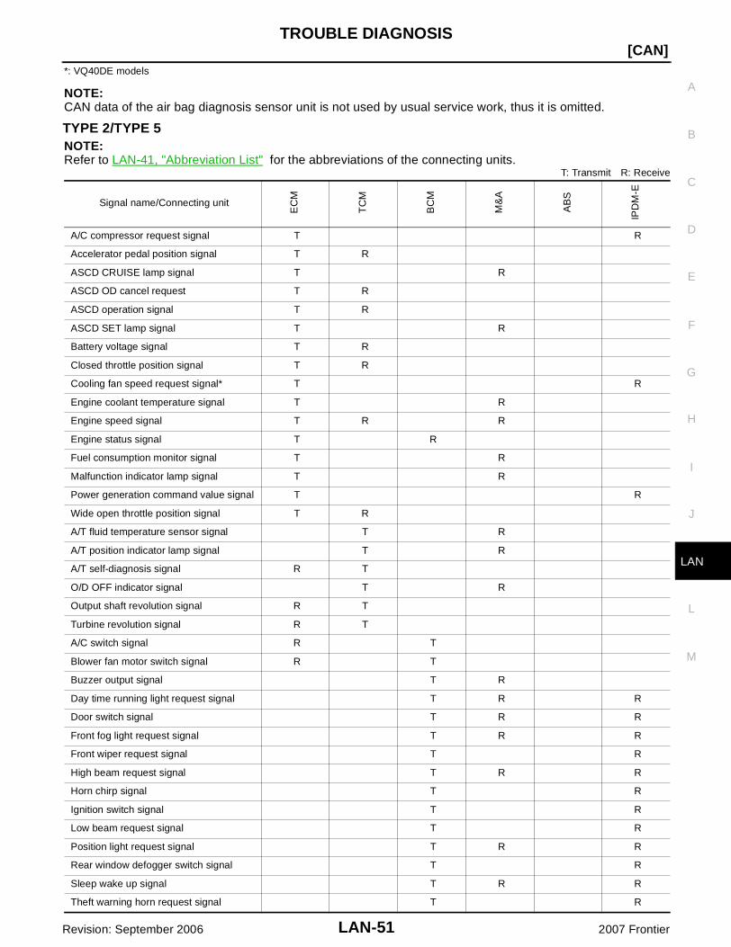
*: VQ40DE models
NOTE:CAN data of the air bag diagnosis sensor unit is not used by usual service work, thus it is omitted.
TYPE 2/TYPE 5NOTE:Refer to LAN-41, "Abbreviation List" for the abbreviations of the connecting units.
T: Transmit R: Receive
Signal name/Connecting unit
EC
M
TC
M
BC
M
M&
A
AB
S
IPD
M-E
A/C compressor request signal T R
Accelerator pedal position signal T R
ASCD CRUISE lamp signal T R
ASCD OD cancel request T R
ASCD operation signal T R
ASCD SET lamp signal T R
Battery voltage signal T R
Closed throttle position signal T R
Cooling fan speed request signal* T R
Engine coolant temperature signal T R
Engine speed signal T R R
Engine status signal T R
Fuel consumption monitor signal T R
Malfunction indicator lamp signal T R
Power generation command value signal T R
Wide open throttle position signal T R
A/T fluid temperature sensor signal T R
A/T position indicator lamp signal T R
A/T self-diagnosis signal R T
O/D OFF indicator signal T R
Output shaft revolution signal R T
Turbine revolution signal R T
A/C switch signal R T
Blower fan motor switch signal R T
Buzzer output signal T R
Day time running light request signal T R R
Door switch signal T R R
Front fog light request signal T R R
Front wiper request signal T R
High beam request signal T R R
Horn chirp signal T R
Ignition switch signal T R
Low beam request signal T R
Position light request signal T R R
Rear window defogger switch signal T R
Sleep wake up signal T R R
Theft warning horn request signal T R

LAN-52
[CAN]TROUBLE DIAGNOSIS
Revision: September 2006 2007 Frontier
*: VQ40DE models
NOTE:CAN data of the air bag diagnosis sensor unit is not used by usual service work, thus it is omitted.
TYPE 4NOTE:Refer to LAN-41, "Abbreviation List" for the abbreviations of the connecting units.
T: Transmit R: Receive
Turn indicator signal T R
1st position switch signal R T
Fuel level sensor signal R T
Overdrive control switch signal R T
Seat belt buckle switch signal R T
Stop lamp switch signal R T
Vehicle speed signalR T
R R R T
ABS warning lamp signal R T
Brake warning lamp signal R T
Front wiper stop position signal R T
High beam status signal R T
Low beam status signal R T
Rear window defogger control signal* R T
Signal name/Connecting unit
EC
M
TC
M
BC
M
M&
A
AB
S
IPD
M-E
Signal name/Connecting unit
EC
M
BC
M
M&
A
AB
S
IPD
M-E
A/C compressor request signal T R
Accelerator pedal position signal T R
ASCD CRUISE lamp signal T R
ASCD SET lamp signal T R
Cooling fan speed request signal T R
Engine coolant temperature signal T R
Engine speed signal T R R
Engine status signal T R
Fuel consumption monitor signal T R
Malfunction indicator lamp signal T R
Power generation command value signal T R
A/C switch signal R T
Blower fan motor switch signal R T
Buzzer output signal T R
Day time running light request signal T R R
Door switch signal T R R
Front fog light request signal T R R
Front wiper request signal T R
High beam request signal T R R
Horn chirp signal T R
TROUBLE DIAGNOSIS
LAN-53
[CAN]
C
D
E
F
G
H
I
J
L
M
A
B
LAN
Revision: September 2006 2007 Frontier
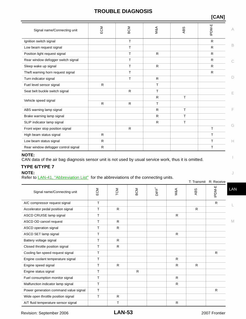
NOTE:CAN data of the air bag diagnosis sensor unit is not used by usual service work, thus it is omitted.
TYPE 6/TYPE 7NOTE:Refer to LAN-41, "Abbreviation List" for the abbreviations of the connecting units.
T: Transmit R: Receive
Ignition switch signal T R
Low beam request signal T R
Position light request signal T R R
Rear window defogger switch signal T R
Sleep wake up signal T R R
Theft warning horn request signal T R
Turn indicator signal T R
Fuel level sensor signal R T
Seat belt buckle switch signal R T
Vehicle speed signalR T
R R T
ABS warning lamp signal R T
Brake warning lamp signal R T
SLIP indicator lamp signal R T
Front wiper stop position signal R T
High beam status signal R T
Low beam status signal R T
Rear window defogger control signal R T
Signal name/Connecting unit
EC
M
BC
M
M&
A
AB
S
IPD
M-E
Signal name/Connecting unit
EC
M
TC
M
BC
M
DIF
F*
M&
A
AB
S
IPD
M-E
A/C compressor request signal T R
Accelerator pedal position signal T R R
ASCD CRUISE lamp signal T R
ASCD OD cancel request T R
ASCD operation signal T R
ASCD SET lamp signal T R
Battery voltage signal T R
Closed throttle position signal T R
Cooling fan speed request signal T R
Engine coolant temperature signal T R
Engine speed signal T R R R
Engine status signal T R
Fuel consumption monitor signal T R
Malfunction indicator lamp signal T R
Power generation command value signal T R
Wide open throttle position signal T R
A/T fluid temperature sensor signal T R

LAN-54
[CAN]TROUBLE DIAGNOSIS
Revision: September 2006 2007 Frontier
*: Models with electronic locking rear differential
NOTE:CAN data of the air bag diagnosis sensor unit is not used by usual service work, thus it is omitted.
TYPE 8NOTE:Refer to LAN-41, "Abbreviation List" for the abbreviations of the connecting units.
A/T position indicator lamp signal T R R
A/T self-diagnosis signal R T
O/D OFF indicator signal T R
Output shaft revolution signal R T
Turbine revolution signal R T
A/C switch signal R T
Blower fan motor switch signal R T
Buzzer output signal T R
Day time running light request signal T R R
Door switch signal T R R
Front fog light request signal T R R
Front wiper request signal T R
High beam request signal T R R
Horn chirp signal T R
Ignition switch signal T R
Low beam request signal T R
Position light request signal T R R
Rear window defogger switch signal T R
Sleep wake up signal T R R
Theft warning horn request signal T R
Turn indicator signal T R
Differential lock indicator signal T R
Differential lock switch signal T R
1st position switch signal R T
Fuel level sensor signal R T
Overdrive control switch signal R T
Seat belt buckle switch signal R T
Stop lamp switch signal R T
Vehicle speed signalR R T
R R R T
ABS warning lamp signal R T
Brake warning lamp signal R T
SLIP indicator lamp signal R T
Front wiper stop position signal R T
High beam status signal R T
Low beam status signal R T
Rear window defogger control signal R T
Signal name/Connecting unit
EC
M
TC
M
BC
M
DIF
F*
M&
A
AB
S
IPD
M-E

TROUBLE DIAGNOSIS
LAN-55
[CAN]
C
D
E
F
G
H
I
J
L
M
A
B
LAN
Revision: September 2006 2007 Frontier
T: Transmit R: Receive
NOTE:CAN data of the air bag diagnosis sensor unit is not used by usual service work, thus it is omitted.
Signal name/Connecting unit
EC
M
4WD
BC
M
M&
A
AB
S
IPD
M-E
A/C compressor request signal T R
Accelerator pedal position signal T
ASCD CRUISE lamp signal T R
ASCD SET lamp signal T R
Cooling fan speed request signal T R
Engine coolant temperature signal T R
Engine speed signal T R R
Engine status signal T R
Fuel consumption monitor signal T R
Malfunction indicator lamp signal T R
Power generation command value signal T R
A/C switch signal R T
Blower fan motor switch signal R T
Buzzer output signal T R
Day time running light request signal T R R
Door switch signal T R R
Front fog light request signal T R R
Front wiper request signal T R
High beam request signal T R R
Horn chirp signal T R
Ignition switch signal T R
Low beam request signal T R
Position light request signal T R R
Rear window defogger switch signal T R
Sleep wake up signal T R R
Theft warning horn request signal T R
Turn indicator signal T R
Fuel level sensor signal R T
Seat belt buckle switch signal R T
Vehicle speed signalR R T
R R T
ABS warning lamp signal R T
Brake warning lamp signal R T
Stop lamp switch signal R T
Front wiper stop position signal R T
High beam status signal R T
Low beam status signal R T
Rear window defogger control signal R T

LAN-56
[CAN]TROUBLE DIAGNOSIS
Revision: September 2006 2007 Frontier
TYPE 9/TYPE 10NOTE:Refer to LAN-41, "Abbreviation List" for the abbreviations of the connecting units.
T: Transmit R: Receive
Signal name/Connecting unit
EC
M
4WD
BC
M
DIF
F*
M&
A
AB
S
IPD
M-E
A/C compressor request signal T R
Accelerator pedal position signal T R
ASCD CRUISE lamp signal T R
ASCD SET lamp signal T R
Cooling fan speed request signal T R
Engine coolant temperature signal T R
Engine speed signal T R R R
Engine status signal T R
Fuel consumption monitor signal T R
Malfunction indicator lamp signal T R
Power generation command value signal T R
4WD shift switch signal T R
A/C switch signal R T
Blower fan motor switch signal R T
Buzzer output signal T R
Day time running light request signal T R R
Door switch signal T R R
Front fog light request signal T R R
Front wiper request signal T R
High beam request signal T R R
Horn chirp signal T R
Ignition switch signal T R
Low beam request signal T R
Position light request signal T R R
Rear window defogger switch signal T R
Sleep wake up signal T R R
Theft warning horn request signal T R
Turn indicator signal T R
Differential lock indicator signal T R
Differential lock switch signal T R
Fuel level sensor signal R T
Seat belt buckle switch signal R T
Vehicle speed signalR R R T
R R T
ABS warning lamp signal R T
Brake warning lamp signal R T
SLIP indicator lamp signal R T
Stop lamp switch signal R T
Front wiper stop position signal R T
High beam status signal R T
TROUBLE DIAGNOSIS
LAN-57
[CAN]
C
D
E
F
G
H
I
J
L
M
A
B
LAN
Revision: September 2006 2007 Frontier
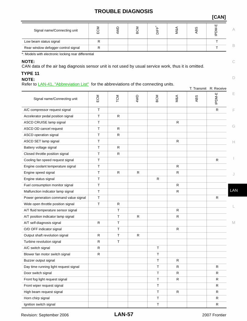
*: Models with electronic locking rear differential
NOTE:CAN data of the air bag diagnosis sensor unit is not used by usual service work, thus it is omitted.
TYPE 11NOTE:Refer to LAN-41, "Abbreviation List" for the abbreviations of the connecting units.
T: Transmit R: Receive
Low beam status signal R T
Rear window defogger control signal R T
Signal name/Connecting unit
EC
M
4WD
BC
M
DIF
F*
M&
A
AB
S
IPD
M-E
Signal name/Connecting unitE
CM
TC
M
4WD
BC
M
M&
A
AB
S
IPD
M-E
A/C compressor request signal T R
Accelerator pedal position signal T R
ASCD CRUISE lamp signal T R
ASCD OD cancel request T R
ASCD operation signal T R
ASCD SET lamp signal T R
Battery voltage signal T R
Closed throttle position signal T R
Cooling fan speed request signal T R
Engine coolant temperature signal T R
Engine speed signal T R R R
Engine status signal T R
Fuel consumption monitor signal T R
Malfunction indicator lamp signal T R
Power generation command value signal T R
Wide open throttle position signal T R
A/T fluid temperature sensor signal T R
A/T position indicator lamp signal T R R
A/T self-diagnosis signal R T
O/D OFF indicator signal T R
Output shaft revolution signal R T R
Turbine revolution signal R T
A/C switch signal R T
Blower fan motor switch signal R T
Buzzer output signal T R
Day time running light request signal T R R
Door switch signal T R R
Front fog light request signal T R R
Front wiper request signal T R
High beam request signal T R R
Horn chirp signal T R
Ignition switch signal T R

LAN-58
[CAN]TROUBLE DIAGNOSIS
Revision: September 2006 2007 Frontier
NOTE:CAN data of the air bag diagnosis sensor unit is not used by usual service work, thus it is omitted.
TYPE 12/TYPE 13NOTE:Refer to LAN-41, "Abbreviation List" for the abbreviations of the connecting units.
T: Transmit R: Receive
Low beam request signal T R
Position light request signal T R R
Rear window defogger switch signal T R
Sleep wake up signal T R R
Theft warning horn request signal T R
Turn indicator signal T R
1st position switch signal R T
Fuel level sensor signal R T
Overdrive control switch signal R T
Seat belt buckle switch signal R T
Stop lamp switch signalR T
R T
Vehicle speed signalR R T
R R R T
ABS warning lamp signal R T
Brake warning lamp signal R T
Front wiper stop position signal R T
High beam status signal R T
Low beam status signal R T
Rear window defogger control signal R T
Signal name/Connecting unit
EC
M
TC
M
4WD
BC
M
M&
A
AB
S
IPD
M-E
Signal name/Connecting unit
EC
M
TC
M
4WD
BC
M
DIF
F*
M&
A
AB
S
IPD
M-E
A/C compressor request signal T R
Accelerator pedal position signal T R R
ASCD CRUISE lamp signal T R
ASCD OD cancel request T R
ASCD operation signal T R
ASCD SET lamp signal T R
Battery voltage signal T R
Closed throttle position signal T R
Cooling fan speed request signal T R
Engine coolant temperature signal T R
Engine speed signal T R R R R
Engine status signal T R
Fuel consumption monitor signal T R
Malfunction indicator lamp signal T R
Power generation command value signal T R

TROUBLE DIAGNOSIS
LAN-59
[CAN]
C
D
E
F
G
H
I
J
L
M
A
B
LAN
Revision: September 2006 2007 Frontier
*: Models with electronic locking rear differential
Wide open throttle position signal T R
A/T fluid temperature sensor signal T R
A/T position indicator lamp signal T R R
A/T self-diagnosis signal R T
O/D OFF indicator signal T R
Output shaft revolution signal R T R
Turbine revolution signal R T
4WD shift switch signal T R
A/C switch signal R T
Blower fan motor switch signal R T
Buzzer output signal T R
Day time running light request signal T R R
Door switch signal T R R
Front fog light request signal T R R
Front wiper request signal T R
High beam request signal T R R
Horn chirp signal T R
Ignition switch signal T R
Low beam request signal T R
Position light request signal T R R
Rear window defogger switch signal T R
Sleep wake up signal T R R
Theft warning horn request signal T R
Turn indicator signal T R
Differential lock indicator signal T R
Differential lock switch signal T R
1st position switch signal R T
Fuel level sensor signal R T
Overdrive control switch signal R T
Seat belt buckle switch signal R T
Stop lamp switch signalR T
R T
Vehicle speed signalR R R T
R R R T
ABS warning lamp signal R T
Brake warning lamp signal R T
SLIP indicator lamp signal R T
Front wiper stop position signal R T
High beam status signal R T
Low beam status signal R T
Rear window defogger control signal R T
Signal name/Connecting unit
EC
M
TC
M
4WD
BC
M
DIF
F*
M&
A
AB
S
IPD
M-E

LAN-60
[CAN]TROUBLE DIAGNOSIS
Revision: September 2006 2007 Frontier
NOTE:CAN data of the air bag diagnosis sensor unit is not used by usual service work, thus it is omitted.
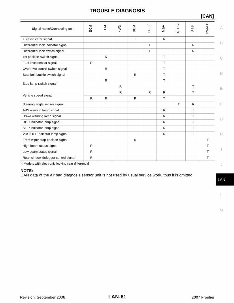
TYPE 14/TYPE 15NOTE:Refer to LAN-41, "Abbreviation List" for the abbreviations of the connecting units.
T: Transmit R: Receive
Signal name/Connecting unit
EC
M
TC
M
4WD
BC
M
DIF
F*
M&
A
ST
RG
AB
S
IPD
M-E
A/C compressor request signal T R
Accelerator pedal position signal T R R
ASCD CRUISE lamp signal T R
ASCD OD cancel request T R
ASCD operation signal T R
ASCD SET lamp signal T R
Battery voltage signal T R
Closed throttle position signal T R
Cooling fan speed request signal T R
Engine coolant temperature signal T R
Engine speed signal T R R R R
Engine status signal T R
Fuel consumption monitor signal T R
Malfunction indicator lamp signal T R
Power generation command value signal T R
Wide open throttle position signal T R
A/T fluid temperature sensor signal T R
A/T position indicator lamp signal T R R R
A/T self-diagnosis signal R T
O/D OFF indicator signal T R
Output shaft revolution signal R T R
Turbine revolution signal R T
4WD shift switch signal T R
A/C switch signal R T
Blower fan motor switch signal R T
Buzzer output signal T R
Day time running light request signal T R R
Door switch signal T R R
Front fog light request signal T R R
Front wiper request signal T R
High beam request signal T R R
Horn chirp signal T R
Ignition switch signal T R
Low beam request signal T R
Position light request signal T R R
Rear window defogger switch signal T R
Sleep wake up signal T R R
Theft warning horn request signal T R
TROUBLE DIAGNOSIS
LAN-61
[CAN]
C
D
E
F
G
H
I
J
L
M
A
B
LAN
Revision: September 2006 2007 Frontier
*: Models with electronic locking rear differential
NOTE:CAN data of the air bag diagnosis sensor unit is not used by usual service work, thus it is omitted.
Turn indicator signal T R
Differential lock indicator signal T R
Differential lock switch signal T R
1st position switch signal R T
Fuel level sensor signal R T
Overdrive control switch signal R T
Seat belt buckle switch signal R T
Stop lamp switch signalR T
R T
Vehicle speed signalR R R T
R R R T
Steering angle sensor signal T R
ABS warning lamp signal R T
Brake warning lamp signal R T
HDC indicator lamp signal R T
SLIP indicator lamp signal R T
VDC OFF indicator lamp signal R T
Front wiper stop position signal R T
High beam status signal R T
Low beam status signal R T
Rear window defogger control signal R T
Signal name/Connecting unit
EC
M
TC
M
4WD
BC
M
DIF
F*
M&
A
ST
RG
AB
S
IPD
M-E
LAN-62
[CAN]TROUBLE DIAGNOSIS
Revision: September 2006 2007 Frontier
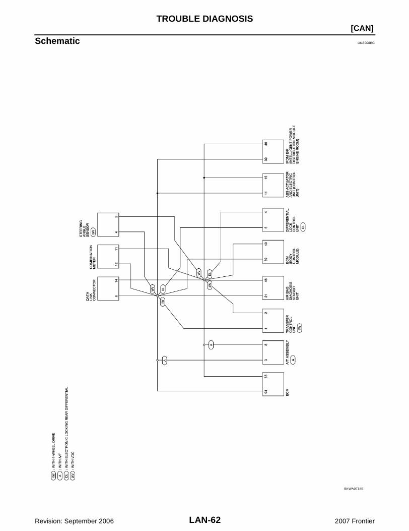
Schematic UKS006EG
BKWA0718E
TROUBLE DIAGNOSIS
LAN-63
[CAN]
C
D
E
F
G
H
I
J
L
M
A
B
LAN
Revision: September 2006 2007 Frontier
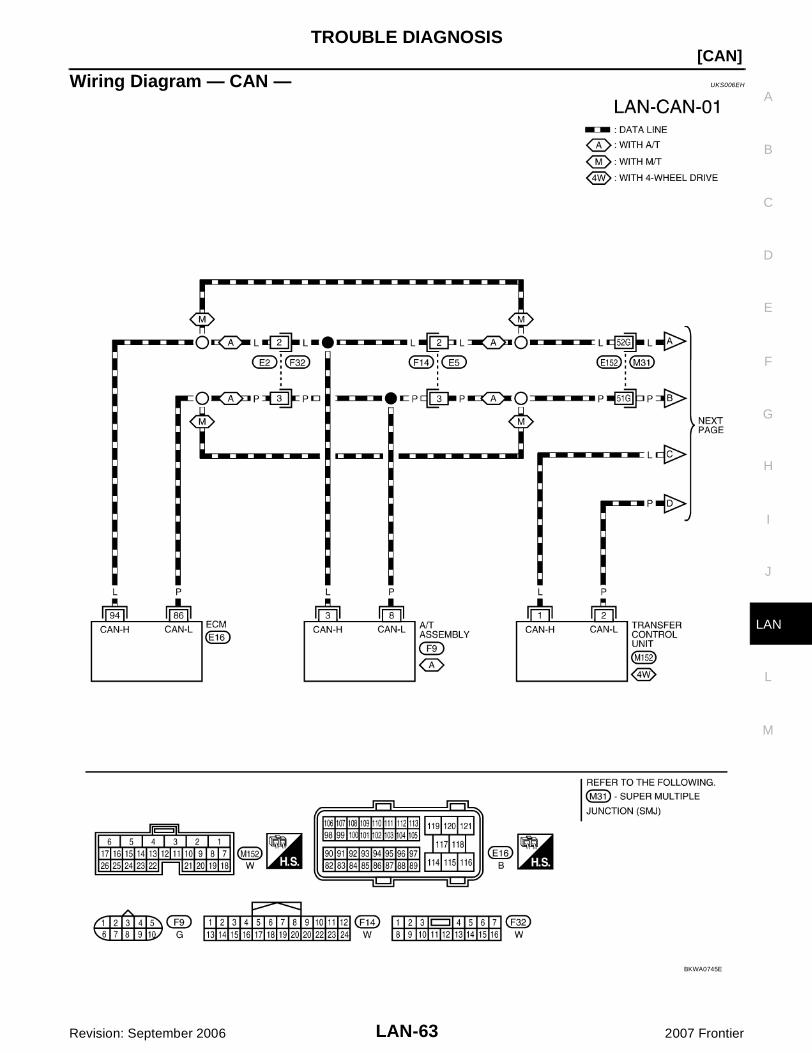
Wiring Diagram — CAN — UKS006EH
BKWA0745E

LAN-64
[CAN]TROUBLE DIAGNOSIS
Revision: September 2006 2007 Frontier
BKWA0719E
TROUBLE DIAGNOSIS
LAN-65
[CAN]
C
D
E
F
G
H
I
J
L
M
A
B
LAN
Revision: September 2006 2007 Frontier
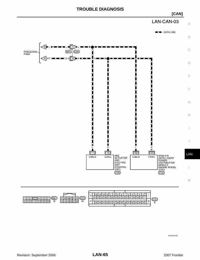
BKWA0720E

LAN-66
[CAN]TROUBLE DIAGNOSIS
Revision: September 2006 2007 Frontier
Interview Sheet UKS006EI
SKIB8898E
TROUBLE DIAGNOSIS
LAN-67
[CAN]
C
D
E
F
G
H
I
J
L
M
A
B
LAN
Revision: September 2006 2007 Frontier
Data Sheet UKS006EJ
CONSULT-II DATA ATTACHMENT SHEET
PKID0617E
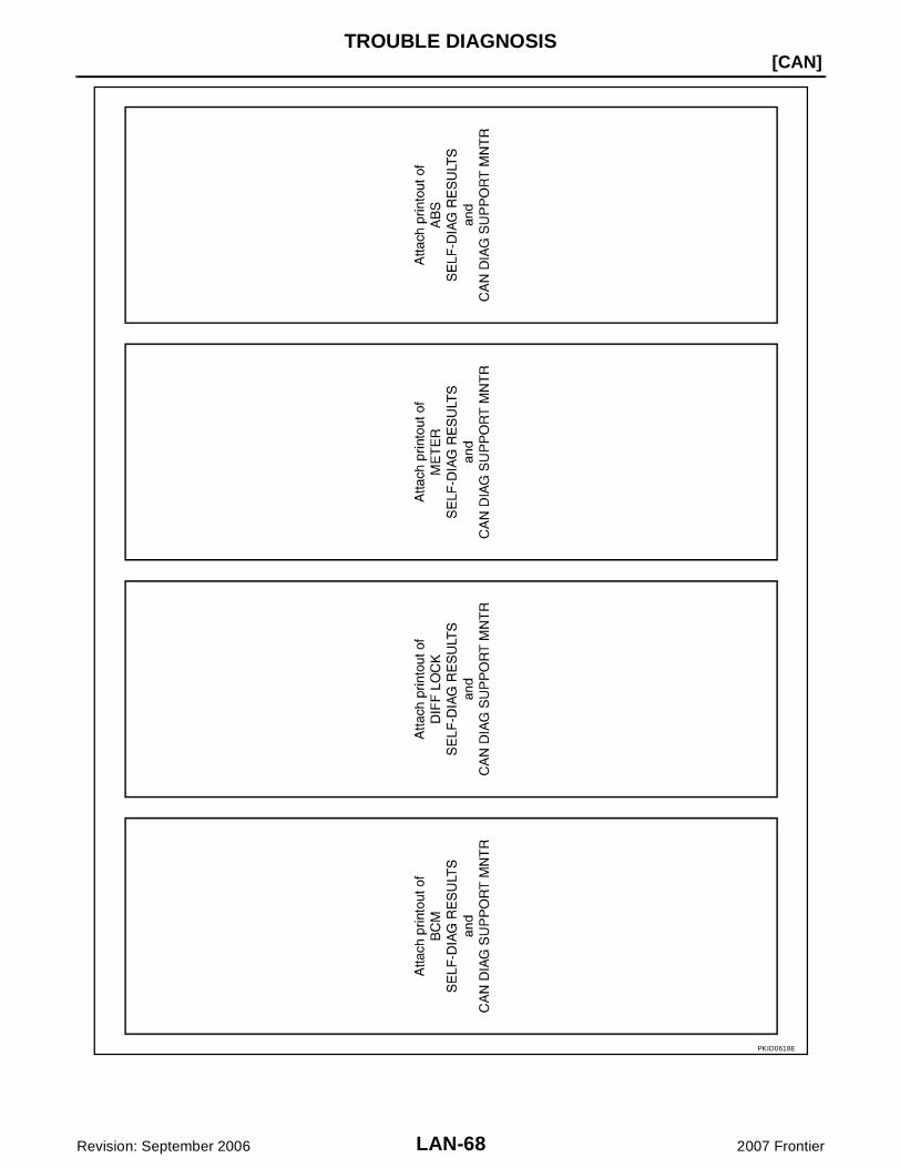
LAN-68
[CAN]TROUBLE DIAGNOSIS
Revision: September 2006 2007 Frontier
PKID0618E

TROUBLE DIAGNOSIS
LAN-69
[CAN]
C
D
E
F
G
H
I
J
L
M
A
B
LAN
Revision: September 2006 2007 Frontier
SKIB8770E

LAN-70
[CAN]TROUBLE DIAGNOSIS
Revision: September 2006 2007 Frontier
CAN System (Type 1) UKS006EK
DIAGNOSIS SHEET
PKID0627E

TROUBLE DIAGNOSIS
LAN-71
[CAN]
C
D
E
F
G
H
I
J
L
M
A
B
LAN
Revision: September 2006 2007 Frontier
CAN System (Type 2) UKS006F1
DIAGNOSIS SHEET
PKID0626E
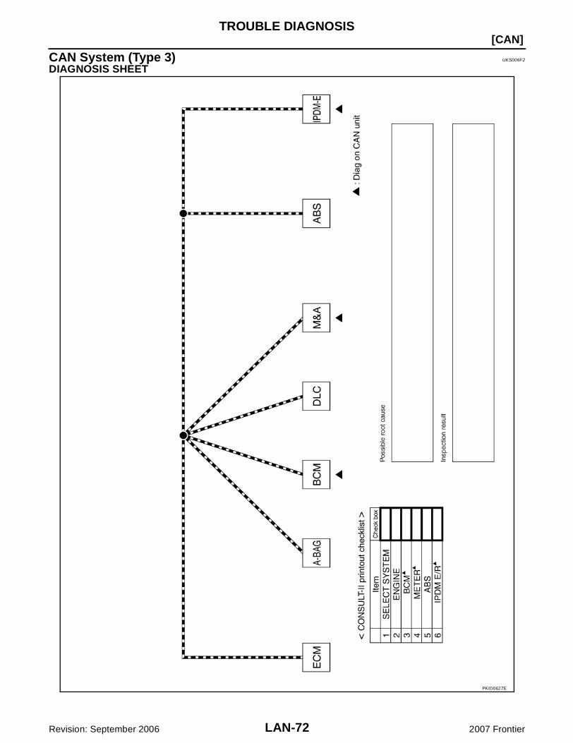
LAN-72
[CAN]TROUBLE DIAGNOSIS
Revision: September 2006 2007 Frontier
CAN System (Type 3) UKS006F2
DIAGNOSIS SHEET
PKID0627E

TROUBLE DIAGNOSIS
LAN-73
[CAN]
C
D
E
F
G
H
I
J
L
M
A
B
LAN
Revision: September 2006 2007 Frontier
CAN System (Type 4) UKS006F3
DIAGNOSIS SHEET
PKID0627E

LAN-74
[CAN]TROUBLE DIAGNOSIS
Revision: September 2006 2007 Frontier
CAN System (Type 5) UKS006F4
DIAGNOSIS SHEET
PKID0626E

TROUBLE DIAGNOSIS
LAN-75
[CAN]
C
D
E
F
G
H
I
J
L
M
A
B
LAN
Revision: September 2006 2007 Frontier
CAN System (Type 6) UKS006F5
DIAGNOSIS SHEET
PKID0626E

LAN-76
[CAN]TROUBLE DIAGNOSIS
Revision: September 2006 2007 Frontier
CAN System (Type 7) UKS006F6
DIAGNOSIS SHEET
PKID0625E

TROUBLE DIAGNOSIS
LAN-77
[CAN]
C
D
E
F
G
H
I
J
L
M
A
B
LAN
Revision: September 2006 2007 Frontier
CAN System (Type 8) UKS006F7
DIAGNOSIS SHEET
PKID0624E
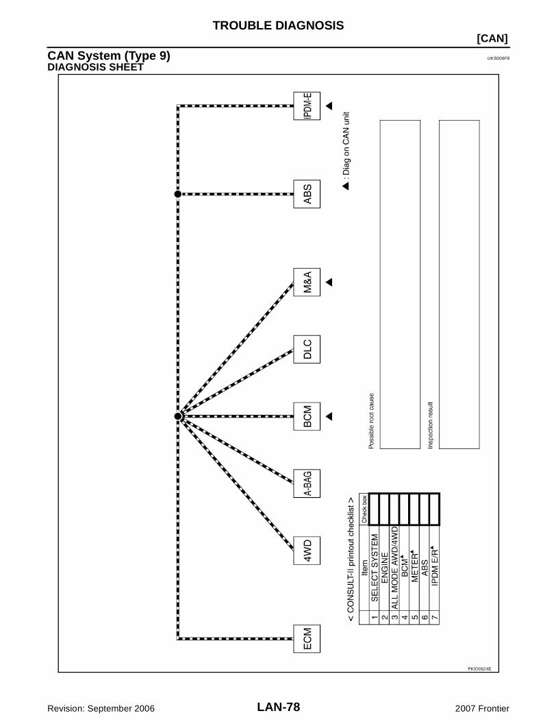
LAN-78
[CAN]TROUBLE DIAGNOSIS
Revision: September 2006 2007 Frontier
CAN System (Type 9) UKS006F8
DIAGNOSIS SHEET
PKID0624E

TROUBLE DIAGNOSIS
LAN-79
[CAN]
C
D
E
F
G
H
I
J
L
M
A
B
LAN
Revision: September 2006 2007 Frontier
CAN System (Type 10) UKS006F9
DIAGNOSIS SHEET
PKID0623E
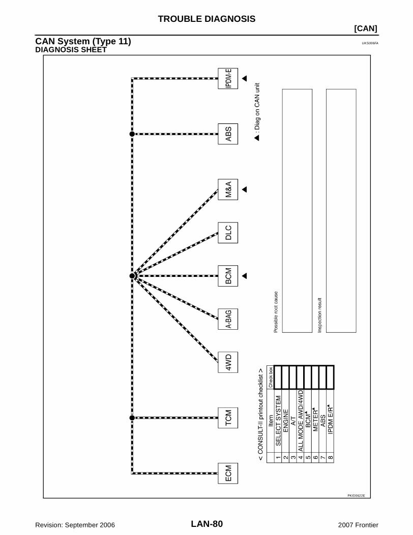
LAN-80
[CAN]TROUBLE DIAGNOSIS
Revision: September 2006 2007 Frontier
CAN System (Type 11) UKS006FA
DIAGNOSIS SHEET
PKID0622E
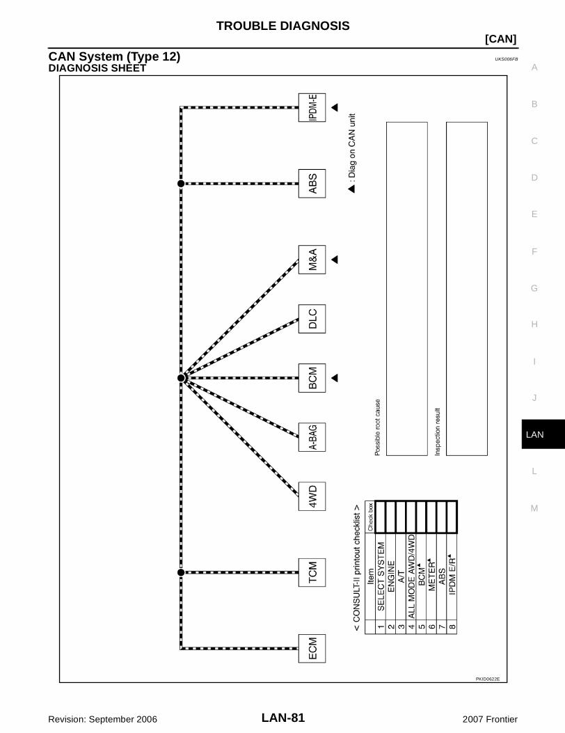
TROUBLE DIAGNOSIS
LAN-81
[CAN]
C
D
E
F
G
H
I
J
L
M
A
B
LAN
Revision: September 2006 2007 Frontier
CAN System (Type 12) UKS006FB
DIAGNOSIS SHEET
PKID0622E

LAN-82
[CAN]TROUBLE DIAGNOSIS
Revision: September 2006 2007 Frontier
CAN System (Type 13) UKS006FC
DIAGNOSIS SHEET
PKID0621E
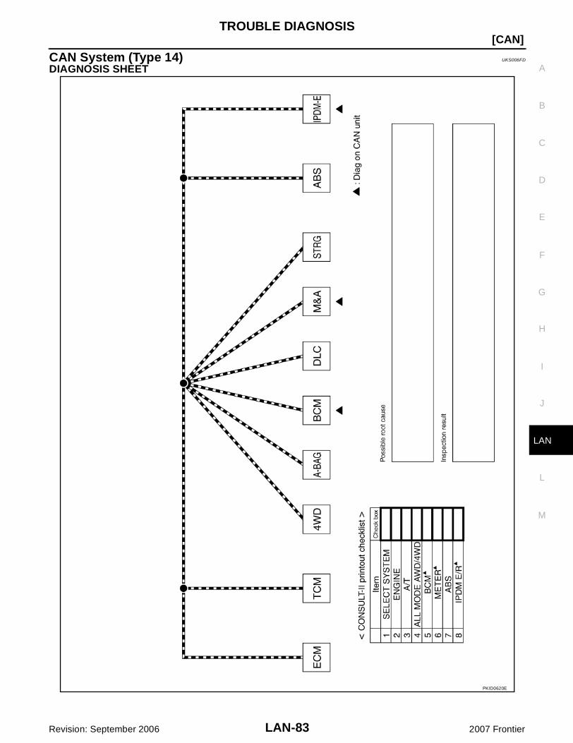
TROUBLE DIAGNOSIS
LAN-83
[CAN]
C
D
E
F
G
H
I
J
L
M
A
B
LAN
Revision: September 2006 2007 Frontier
CAN System (Type 14) UKS006FD
DIAGNOSIS SHEET
PKID0620E

LAN-84
[CAN]TROUBLE DIAGNOSIS
Revision: September 2006 2007 Frontier
CAN System (Type 15) UKS006FE
DIAGNOSIS SHEET
PKID0619E

TROUBLE DIAGNOSIS
LAN-85
[CAN]
C
D
E
F
G
H
I
J
L
M
A
B
LAN
Revision: September 2006 2007 Frontier
Component Parts Location UKS006EL
Harness Layout UKS006EM
Refer to PG-44, "Harness Layout" .
1. IPDM E/R E122 2. ECM E16 3. Combination meter M24
4. BCM M18 5. ABS actuator and electric unit (con-trol unit) E125
6. Transfer control unit M152
7. Differential lock control unit M70 8. Data link connector M22 9. Steering angle sensor M47
10. Air bag diagnosis sensor unit M35 11. A/T assembly F9
BKIA0200E
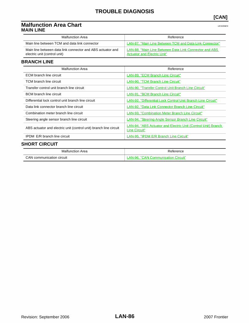
LAN-86
[CAN]TROUBLE DIAGNOSIS
Revision: September 2006 2007 Frontier
Malfunction Area Chart UKS006EN
MAIN LINE
BRANCH LINE
SHORT CIRCUIT
Malfunction Area Reference
Main line between TCM and data link connector LAN-87, "Main Line Between TCM and Data Link Connector"
Main line between data link connector and ABS actuator and electric unit (control unit)
LAN-88, "Main Line Between Data Link Connector and ABS Actuator and Electric Unit"
Malfunction Area Reference
ECM branch line circuit LAN-89, "ECM Branch Line Circuit"
TCM branch line circuit LAN-90, "TCM Branch Line Circuit"
Transfer control unit branch line circuit LAN-90, "Transfer Control Unit Branch Line Circuit"
BCM branch line circuit LAN-91, "BCM Branch Line Circuit"
Differential lock control unit branch line circuit LAN-92, "Differential Lock Control Unit Branch Line Circuit"
Data link connector branch line circuit LAN-92, "Data Link Connector Branch Line Circuit"
Combination meter branch line circuit LAN-93, "Combination Meter Branch Line Circuit"
Steering angle sensor branch line circuit LAN-94, "Steering Angle Sensor Branch Line Circuit"
ABS actuator and electric unit (control unit) branch line circuit LAN-94, "ABS Actuator and Electric Unit (Control Unit) Branch Line Circuit"
IPDM E/R branch line circuit LAN-95, "IPDM E/R Branch Line Circuit"
Malfunction Area Reference
CAN communication circuit LAN-96, "CAN Communication Circuit"

TROUBLE DIAGNOSIS
LAN-87
[CAN]
C
D
E
F
G
H
I
J
L
M
A
B
LAN
Revision: September 2006 2007 Frontier
Main Line Between TCM and Data Link Connector UKS006EO
INSPECTION PROCEDURE
1. CHECK CONNECTOR
1. Turn the ignition switch OFF.2. Disconnect the battery cable from the negative terminal.3. Check the following terminals and connectors for damage, bend and loose connection (connector side
and harness side).– Harness connector F14– Harness connector E5– Harness connector E152– Harness connector M31OK or NGOK >> GO TO 2.NG >> Repair the terminal and connector.
2. CHECK HARNESS CONTINUITY (OPEN CIRCUIT)
1. Disconnect the following harness connectors.– A/T assembly connector– Harness connector F14 and E52. Check the continuity between the A/T assembly harness connector and the harness connector.
OK or NGOK >> GO TO 3.NG >> Repair the main line between the A/T assembly and the harness connector F14.
3. CHECK HARNESS CONTINUITY (OPEN CIRCUIT)
1. Disconnect the harness connectors E152 and M31.2. Check the continuity between harness connectors.
OK or NGOK >> GO TO 4.NG >> Repair the main line between the harness connector E5 and the harness connector E152.
A/T assembly harness connector Harness connectorContinuity
Connector No. Terminal No. Connector No. Terminal No.
F93
F142 Yes
8 3 Yes
Harness connector Harness connectorContinuity
Connector No. Terminal No. Connector No. Terminal No.
E52
E15252G Yes
3 51G Yes
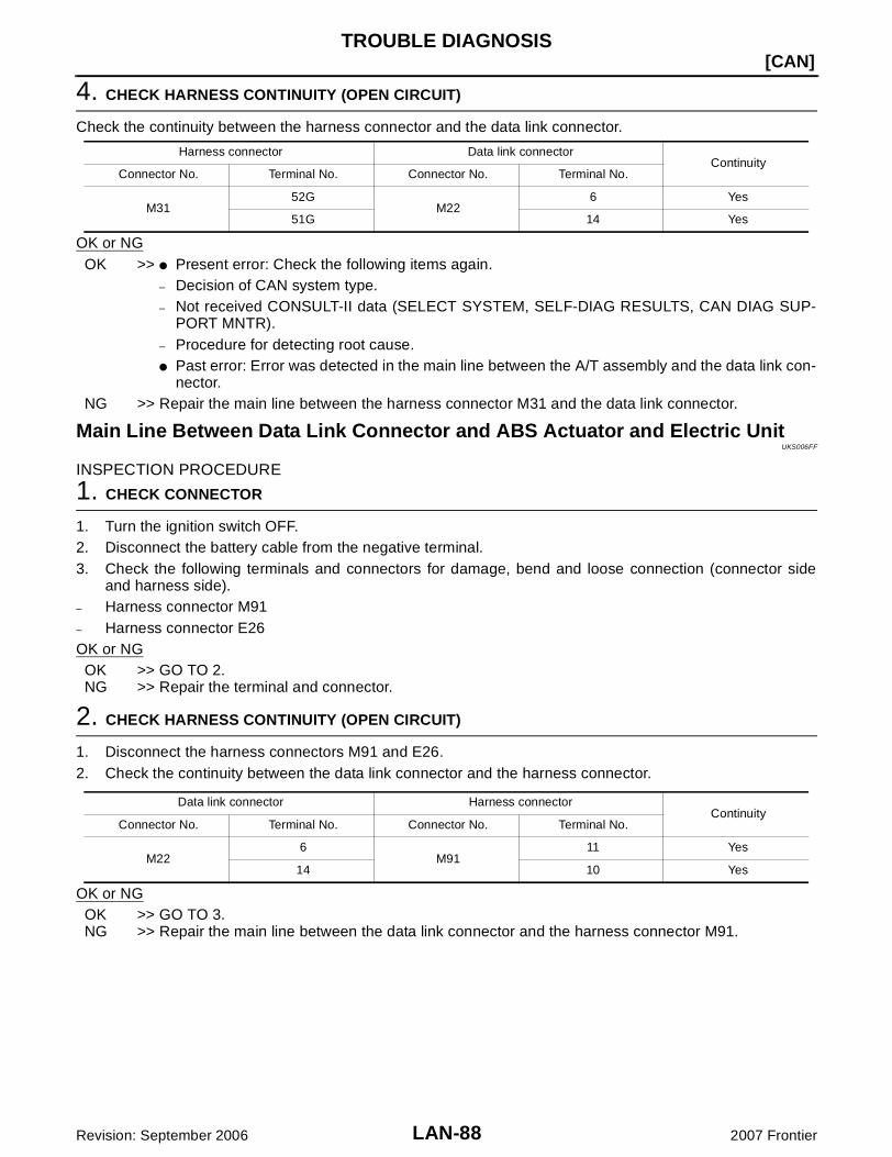
LAN-88
[CAN]TROUBLE DIAGNOSIS
Revision: September 2006 2007 Frontier
4. CHECK HARNESS CONTINUITY (OPEN CIRCUIT)
Check the continuity between the harness connector and the data link connector.
OK or NGOK >> Present error: Check the following items again.
– Decision of CAN system type.– Not received CONSULT-II data (SELECT SYSTEM, SELF-DIAG RESULTS, CAN DIAG SUP-
PORT MNTR).– Procedure for detecting root cause. Past error: Error was detected in the main line between the A/T assembly and the data link con-
nector.NG >> Repair the main line between the harness connector M31 and the data link connector.
Main Line Between Data Link Connector and ABS Actuator and Electric UnitUKS006FF
INSPECTION PROCEDURE
1. CHECK CONNECTOR
1. Turn the ignition switch OFF.2. Disconnect the battery cable from the negative terminal.3. Check the following terminals and connectors for damage, bend and loose connection (connector side
and harness side).– Harness connector M91– Harness connector E26OK or NG
OK >> GO TO 2.NG >> Repair the terminal and connector.
2. CHECK HARNESS CONTINUITY (OPEN CIRCUIT)
1. Disconnect the harness connectors M91 and E26.2. Check the continuity between the data link connector and the harness connector.
OK or NGOK >> GO TO 3.NG >> Repair the main line between the data link connector and the harness connector M91.
Harness connector Data link connectorContinuity
Connector No. Terminal No. Connector No. Terminal No.
M3152G
M226 Yes
51G 14 Yes
Data link connector Harness connectorContinuity
Connector No. Terminal No. Connector No. Terminal No.
M226
M9111 Yes
14 10 Yes
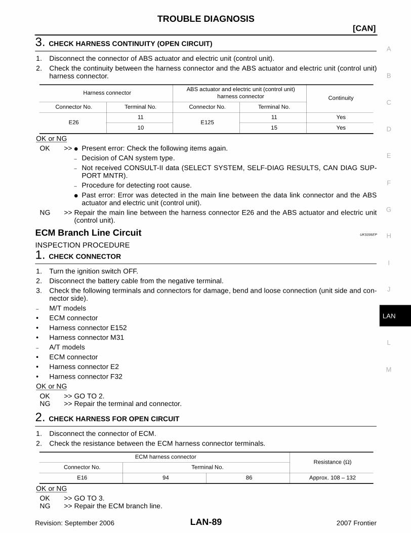
TROUBLE DIAGNOSIS
LAN-89
[CAN]
C
D
E
F
G
H
I
J
L
M
A
B
LAN
Revision: September 2006 2007 Frontier
3. CHECK HARNESS CONTINUITY (OPEN CIRCUIT)
1. Disconnect the connector of ABS actuator and electric unit (control unit).2. Check the continuity between the harness connector and the ABS actuator and electric unit (control unit)
harness connector.
OK or NGOK >> Present error: Check the following items again.
– Decision of CAN system type.– Not received CONSULT-II data (SELECT SYSTEM, SELF-DIAG RESULTS, CAN DIAG SUP-
PORT MNTR).– Procedure for detecting root cause. Past error: Error was detected in the main line between the data link connector and the ABS
actuator and electric unit (control unit).NG >> Repair the main line between the harness connector E26 and the ABS actuator and electric unit
(control unit).
ECM Branch Line Circuit UKS006EP
INSPECTION PROCEDURE
1. CHECK CONNECTOR
1. Turn the ignition switch OFF.2. Disconnect the battery cable from the negative terminal.3. Check the following terminals and connectors for damage, bend and loose connection (unit side and con-
nector side).– M/T models• ECM connector• Harness connector E152• Harness connector M31– A/T models• ECM connector• Harness connector E2• Harness connector F32OK or NGOK >> GO TO 2.NG >> Repair the terminal and connector.
2. CHECK HARNESS FOR OPEN CIRCUIT
1. Disconnect the connector of ECM.2. Check the resistance between the ECM harness connector terminals.
OK or NGOK >> GO TO 3.NG >> Repair the ECM branch line.
Harness connectorABS actuator and electric unit (control unit)
harness connector Continuity
Connector No. Terminal No. Connector No. Terminal No.
E2611
E12511 Yes
10 15 Yes
ECM harness connectorResistance (Ω)
Connector No. Terminal No.
E16 94 86 Approx. 108 – 132
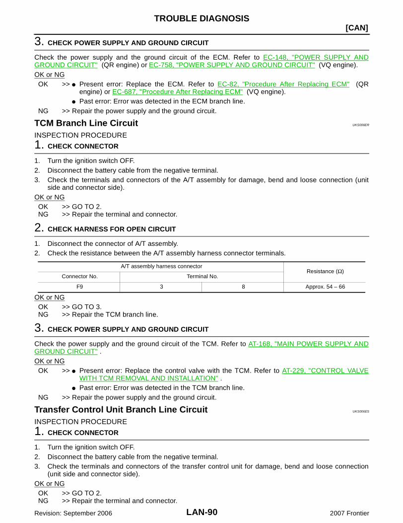
LAN-90
[CAN]TROUBLE DIAGNOSIS
Revision: September 2006 2007 Frontier
3. CHECK POWER SUPPLY AND GROUND CIRCUIT
Check the power supply and the ground circuit of the ECM. Refer to EC-148, "POWER SUPPLY ANDGROUND CIRCUIT" (QR engine) or EC-758, "POWER SUPPLY AND GROUND CIRCUIT" (VQ engine).OK or NG
OK >> Present error: Replace the ECM. Refer to EC-82, "Procedure After Replacing ECM" (QRengine) or EC-687, "Procedure After Replacing ECM" (VQ engine).
Past error: Error was detected in the ECM branch line.NG >> Repair the power supply and the ground circuit.
TCM Branch Line Circuit UKS006ER
INSPECTION PROCEDURE
1. CHECK CONNECTOR
1. Turn the ignition switch OFF.2. Disconnect the battery cable from the negative terminal.3. Check the terminals and connectors of the A/T assembly for damage, bend and loose connection (unit
side and connector side).OK or NG
OK >> GO TO 2.NG >> Repair the terminal and connector.
2. CHECK HARNESS FOR OPEN CIRCUIT
1. Disconnect the connector of A/T assembly.2. Check the resistance between the A/T assembly harness connector terminals.
OK or NGOK >> GO TO 3.NG >> Repair the TCM branch line.
3. CHECK POWER SUPPLY AND GROUND CIRCUIT
Check the power supply and the ground circuit of the TCM. Refer to AT-168, "MAIN POWER SUPPLY ANDGROUND CIRCUIT" .OK or NG
OK >> Present error: Replace the control valve with the TCM. Refer to AT-229, "CONTROL VALVEWITH TCM REMOVAL AND INSTALLATION" .
Past error: Error was detected in the TCM branch line.NG >> Repair the power supply and the ground circuit.
Transfer Control Unit Branch Line Circuit UKS006ES
INSPECTION PROCEDURE
1. CHECK CONNECTOR
1. Turn the ignition switch OFF.2. Disconnect the battery cable from the negative terminal.3. Check the terminals and connectors of the transfer control unit for damage, bend and loose connection
(unit side and connector side).OK or NG
OK >> GO TO 2.NG >> Repair the terminal and connector.
A/T assembly harness connectorResistance (Ω)
Connector No. Terminal No.
F9 3 8 Approx. 54 – 66

TROUBLE DIAGNOSIS
LAN-91
[CAN]
C
D
E
F
G
H
I
J
L
M
A
B
LAN
Revision: September 2006 2007 Frontier
2. CHECK HARNESS FOR OPEN CIRCUIT
1. Disconnect the connector of transfer control unit.2. Check the resistance between the transfer control unit harness connector terminals.
OK or NGOK >> GO TO 3.NG >> Repair the transfer control unit branch line.
3. CHECK POWER SUPPLY AND GROUND CIRCUIT
Check the power supply and the ground circuit of the transfer control unit. Refer to TF-51, "Power Supply Cir-cuit For Transfer Control Unit" .OK or NGOK >> Present error: Replace the transfer control unit. Refer to TF-102, "Removal and Installation" .
Past error: Error was detected in the transfer control unit branch line.NG >> Repair the power supply and the ground circuit.
BCM Branch Line Circuit UKS006ET
INSPECTION PROCEDURE
1. CHECK CONNECTOR
1. Turn the ignition switch OFF.2. Disconnect the battery cable from the negative terminal.3. Check the terminals and connectors of the BCM for damage, bend and loose connection (unit side and
connector side).OK or NGOK >> GO TO 2.NG >> Repair the terminal and connector.
2. CHECK HARNESS FOR OPEN CIRCUIT
1. Disconnect the connector of BCM.2. Check the resistance between the BCM harness connector terminals.
OK or NGOK >> GO TO 3.NG >> Repair the BCM branch line.
3. CHECK POWER SUPPLY AND GROUND CIRCUIT
Check the power supply and the ground circuit of the BCM. Refer to BCS-16, "BCM Power Supply and GroundCircuit Check" .OK or NGOK >> Present error: Replace the BCM. Refer to BCS-25, "Removal and Installation" .
Past error: Error was detected in the BCM branch line.NG >> Repair the power supply and the ground circuit.
Transfer control unit harness connectorResistance (Ω)
Connector No. Terminal No.
M152 1 2 Approx. 54 – 66
BCM harness connectorResistance (Ω)
Connector No. Terminal No.
M18 39 40 Approx. 54 – 66

LAN-92
[CAN]TROUBLE DIAGNOSIS
Revision: September 2006 2007 Frontier
Differential Lock Control Unit Branch Line Circuit UKS006EU
INSPECTION PROCEDURE
1. CHECK CONNECTOR
1. Turn the ignition switch OFF.2. Disconnect the battery cable from the negative terminal.3. Check the terminals and connectors of the differential lock control unit for damage, bend and loose con-
nection (unit side and connector side).OK or NG
OK >> GO TO 2.NG >> Repair the terminal and connector.
2. CHECK HARNESS FOR OPEN CIRCUIT
1. Disconnect the connector of differential lock control unit.2. Check the resistance between the differential lock control unit harness connector terminals.
OK or NGOK >> GO TO 3.NG >> Repair the differential lock control unit branch line.
3. CHECK POWER SUPPLY AND GROUND CIRCUIT
Check the power supply and the ground circuit of the differential lock control unit. Refer to RFD-91, "PowerSupply Circuit For Differential Lock Control Unit" .OK or NG
OK >> Present error: Replace the differential lock control unit. Refer to RFD-110, "Removal and Instal-lation" .
Past error: Error was detected in the differential lock control unit branch line.NG >> Repair the power supply and the ground circuit.
Data Link Connector Branch Line Circuit UKS006EV
INSPECTION PROCEDURE
1. CHECK CONNECTOR
1. Turn the ignition switch OFF.2. Disconnect the battery cable from the negative terminal.3. Check the terminals and connectors of the data link connector for damage, bend and loose connection
(connector side and harness side).OK or NG
OK >> GO TO 2.NG >> Repair the terminal and connector.
Differential lock control unit harness connectorResistance (Ω)
Connector No. Terminal No.
M70 5 4 Approx. 54 – 66
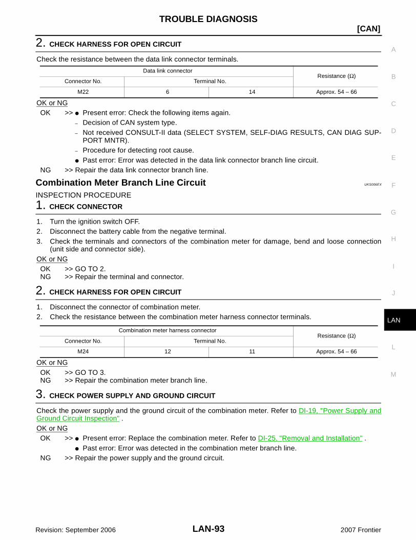
TROUBLE DIAGNOSIS
LAN-93
[CAN]
C
D
E
F
G
H
I
J
L
M
A
B
LAN
Revision: September 2006 2007 Frontier
2. CHECK HARNESS FOR OPEN CIRCUIT
Check the resistance between the data link connector terminals.
OK or NGOK >> Present error: Check the following items again.
– Decision of CAN system type.– Not received CONSULT-II data (SELECT SYSTEM, SELF-DIAG RESULTS, CAN DIAG SUP-
PORT MNTR).– Procedure for detecting root cause. Past error: Error was detected in the data link connector branch line circuit.
NG >> Repair the data link connector branch line.
Combination Meter Branch Line Circuit UKS006EX
INSPECTION PROCEDURE
1. CHECK CONNECTOR
1. Turn the ignition switch OFF.2. Disconnect the battery cable from the negative terminal.3. Check the terminals and connectors of the combination meter for damage, bend and loose connection
(unit side and connector side).OK or NGOK >> GO TO 2.NG >> Repair the terminal and connector.
2. CHECK HARNESS FOR OPEN CIRCUIT
1. Disconnect the connector of combination meter.2. Check the resistance between the combination meter harness connector terminals.
OK or NGOK >> GO TO 3.NG >> Repair the combination meter branch line.
3. CHECK POWER SUPPLY AND GROUND CIRCUIT
Check the power supply and the ground circuit of the combination meter. Refer to DI-19, "Power Supply andGround Circuit Inspection" .OK or NGOK >> Present error: Replace the combination meter. Refer to DI-25, "Removal and Installation" .
Past error: Error was detected in the combination meter branch line.NG >> Repair the power supply and the ground circuit.
Data link connectorResistance (Ω)
Connector No. Terminal No.
M22 6 14 Approx. 54 – 66
Combination meter harness connectorResistance (Ω)
Connector No. Terminal No.
M24 12 11 Approx. 54 – 66

LAN-94
[CAN]TROUBLE DIAGNOSIS
Revision: September 2006 2007 Frontier
Steering Angle Sensor Branch Line Circuit UKS006EY
INSPECTION PROCEDURE
1. CHECK CONNECTOR
1. Turn the ignition switch OFF.2. Disconnect the battery cable from the negative terminal.3. Check the terminals and connectors of the steering angle sensor for damage, bend and loose connection
(unit side and connector side).OK or NG
OK >> GO TO 2.NG >> Repair the terminal and connector.
2. CHECK HARNESS FOR OPEN CIRCUIT
1. Disconnect the connector of steering angle sensor.2. Check the resistance between the steering angle sensor harness connector terminals.
OK or NGOK >> GO TO 3.NG >> Repair the steering angle sensor branch line.
3. CHECK POWER SUPPLY AND GROUND CIRCUIT
Check the power supply and the ground circuit of the steering angle sensor. Refer to BRC-97, "Schematic" .OK or NG
OK >> Present error: Replace the steering angle sensor. Refer to BRC-151, "Removal and Installa-tion" .
Past error: Error was detected in the steering angle sensor branch line.NG >> Repair the power supply and the ground circuit.
ABS Actuator and Electric Unit (Control Unit) Branch Line Circuit UKS006EQ
INSPECTION PROCEDURE
1. CHECK CONNECTOR
1. Turn the ignition switch OFF.2. Disconnect the battery cable from the negative terminal.3. Check the terminals and connectors of the ABS actuator and electric unit (control unit) for damage, bend
and loose connection (unit side and connector side).OK or NG
OK >> GO TO 2.NG >> Repair the terminal and connector.
Steering angle sensor harness connectorResistance (Ω)
Connector No. Terminal No.
M47 4 5 Approx. 54 – 66

TROUBLE DIAGNOSIS
LAN-95
[CAN]
C
D
E
F
G
H
I
J
L
M
A
B
LAN
Revision: September 2006 2007 Frontier
2. CHECK HARNESS FOR OPEN CIRCUIT
1. Disconnect the connector of ABS actuator and electric unit (control unit).2. Check the resistance between the ABS actuator and electric unit (control unit) harness connector termi-
nals.
OK or NGOK >> GO TO 3.NG >> Repair the ABS actuator and electric unit (control unit) branch line.
3. CHECK POWER SUPPLY AND GROUND CIRCUIT
Check the power supply and the ground circuit of the ABS actuator and electric unit (control unit). Refer to thefollowing. Models with ABS: BRC-14, "Schematic" Models with ABLS: BRC-51, "Schematic" Models with VDC: BRC-97, "Schematic"OK or NGOK >> Present error: Replace the ABS actuator and electric unit (control unit). Refer to the following.
– Models with ABS: BRC-38, "Removal and Installation"– Models with ABLS: BRC-82, "Removal and Installation"– Models with VDC: BRC-149, "Removal and Installation" Past error: Error was detected in the ABS actuator and electric unit (control unit) branch line.
NG >> Repair the power supply and the ground circuit.
IPDM E/R Branch Line Circuit UKS006EZ
INSPECTION PROCEDURE
1. CHECK CONNECTOR
1. Turn the ignition switch OFF.2. Disconnect the battery cable from the negative terminal.3. Check the terminals and connectors of the IPDM E/R for damage, bend and loose connection (unit side
and connector side).OK or NGOK >> GO TO 2.NG >> Repair the terminal and connector.
2. CHECK HARNESS FOR OPEN CIRCUIT
1. Disconnect the connector of IPDM E/R.2. Check the resistance between the IPDM E/R harness connector terminals.
OK or NGOK >> GO TO 3.NG >> Repair the IPDM E/R branch line.
ABS actuator and electric unit (control unit) harness connectorResistance (Ω)
Connector No. Terminal No.
E125 11 15 Approx. 54 – 66
IPDM E/R harness connectorResistance (Ω)
Connector No. Terminal No.
E122 39 40 Approx. 108 – 132

LAN-96
[CAN]TROUBLE DIAGNOSIS
Revision: September 2006 2007 Frontier
3. CHECK POWER SUPPLY AND GROUND CIRCUIT
Check the power supply and the ground circuit of the IPDM E/R. Refer to PG-30, "IPDM E/R Power/GroundCircuit Inspection" .OK or NG
OK >> Present error: Replace the IPDM E/R. Refer to PG-32, "Removal and Installation of IPDM E/R".
Past error: Error was detected in the IPDM E/R branch line.NG >> Repair the power supply and the ground circuit.
CAN Communication Circuit UKS006F0
INSPECTION PROCEDURE
1. CONNECTOR INSPECTION
1. Turn the ignition switch OFF2. Disconnect the battery cable from the negative terminal.3. Disconnect all the unit connectors on CAN communication system.4. Check terminals and connectors for damage, bend and loose connection.OK or NG
OK >> GO TO 2.NG >> Repair the terminal and connector.
2. CHECK HARNESS CONTINUITY (SHORT CIRCUIT)
Check the continuity between the data link connector terminals.
OK or NGOK >> GO TO 3.NG >> Check the harness and repair the root cause.
3. CHECK HARNESS CONTINUITY (SHORT CIRCUIT)
Check the continuity between the data link connector and the ground.
OK or NGOK >> GO TO 4.NG >> Check the harness and repair the root cause.
Data link connectorContinuity
Connector No. Terminal No.
M22 6 14 No
Data link connector
Ground
ContinuityConnector No. Terminal No.
M226 No
14 No

TROUBLE DIAGNOSIS
LAN-97
[CAN]
C
D
E
F
G
H
I
J
L
M
A
B
LAN
Revision: September 2006 2007 Frontier
4. CHECK ECM AND IPDM E/R TERMINATION CIRCUIT
1. Remove the ECM and the IPDM E/R.2. Check the resistance between the ECM terminals.
3. Check the resistance between the IPDM E/R terminals.
OK or NGOK >> GO TO 5.NG >> Replace the ECM and/or the IPDM E/R.
5. CHECK SYMPTOM
Connect all the connectors. Check if the symptoms described in the “Symptom (Results from interview withcustomer)” are reproduced. Inspection resultReproduced>>GO TO 6.Non-reproduced>>Start the diagnosis again. Follow the trouble diagnosis procedure when past error is
detected.
6. CHECK UNIT REPRODUCTION
Perform the reproduction test as per the following procedure for each unit.1. Turn the ignition switch OFF2. Disconnect the battery cable from the negative terminal.3. Disconnect all the unit connectors on CAN communication system.
NOTE:ECM and IPDM E/R have a termination circuit. Check other units first.
4. Connect the battery cable to the negative terminal. Check if the symptoms described in the “Symptom(Results from interview with customer)” are reproduced. NOTE:Although unit-related error symptoms occur, do not confuse them with other symptoms.
Inspection resultReproduced>>Connect the connector. Check other units as per the above procedure.Non-reproduced>>Replace the unit whose connector was disconnected.
ECMResistance (Ω)
Terminal No.
94 86 Approx. 108 – 132
IPDM E/RResistance (Ω)
Terminal No.
39 40 Approx. 108 – 132 LKIA0037E

LAN-98
[CAN]TROUBLE DIAGNOSIS
Revision: September 2006 2007 Frontier