Embed Size (px)
Citation preview

- 1 -
Rev.05e July 11, 2017 NJR4265R
K-Band Doppler Sensor Module
RF Frequency: 24.05 to 24.25 GHz
Model No. NJR4265R series
Frequency Line-up: F1: 24.05 to 24.25 GHz / EU F2: 24.15 to 24.25 GHz / EU F3: 24.075 to 24.175 GHz / US
J1: 24.05 to 24.25 GHz / JAPAN Software Version: C1: Original Release
Specifications Rev.05e July 11, 2017
© Copyright 2017
New Japan Radio Co., Ltd. Microwave Division
-Notice of Proprietary Information-
Documents and contents are proprietary to New Japan Radio Co., Ltd. This publication and its contents may not be reproduced or distributed for any
other purpose without the written permission of New Japan Radio Co., Ltd.
Released

NJR4265R series
- 2 -
Rev.05e July 11, 2017 NJR4265R
24GHz Microwave Intelligent Motion Sensor for Short Distance, Low Speed Applications
NJR4265R is intelligent motion sensor that is designed for the sensing of short distance low speed movement object of pedestrian etc. The steady sensing of moving object is realized by embedded software. It is suitable for the built-in use of the sensing function to various equipment as all functions are integrated in a small package and it can easily control from PC/MCU by UART interface. Further, stand-alone operation is also possible.
Features: Motion sensor using the 24GHz Microwave Doppler Antenna, RF circuit, IF amp, MCU and voltage
regulator are integrated in a small package (14 x 20.4 x 8.8mm)
Communication with PC/MCU is available by UART interface and stand-alone operation is also possible
Signal processing software for the steady sensing Enhancing the signal from movement object
and decreasing random noises Decreasing the mutual interference between
sensors Identification of direction for movement object
(approaching and leaving). Low voltage operation and low power consumption Sleep mode for reducing power when unnecessary
Applications: Various equipment control by human sensing Energy saving management Entrance and exit management Safety and Security
Functional Brock diagram:
NJR4265R series
- 3 -
Rev.05e July 11, 2017 NJR4265R
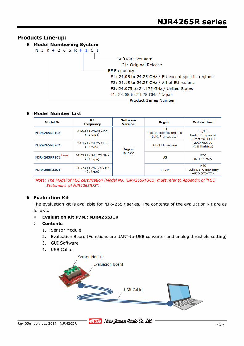
Products Line-up: Model Numbering System
Model Number List
*Note: The Model of FCC certification (Model No. NJR4265RF3C1) must refer to Appendix of “FCC
Statement of NJR4265RF3”.
Evaluation Kit The evaluation kit is available for NJR4265R series. The contents of the evaluation kit are as follows. Evaluation Kit P/N.: NJR4265J1K Contents
1. Sensor Module 2. Evaluation Board (Functions are UART-to-USB convertor and analog threshold setting) 3. GUI Software 4. USB Cable
NJR4265R series
- 4 -
Rev.05e July 11, 2017 NJR4265R
1. Absolute Maximum Rating ITEM MIN. TYP. MAX. UNITS REMARKS
Supply Voltage 0 ― 6.5 V Operating Temperature -40 ― +85 °C Storage Temperature -40 ― +85 °C
NJR4265R series
- 5 -
Rev.05e July 11, 2017 NJR4265R
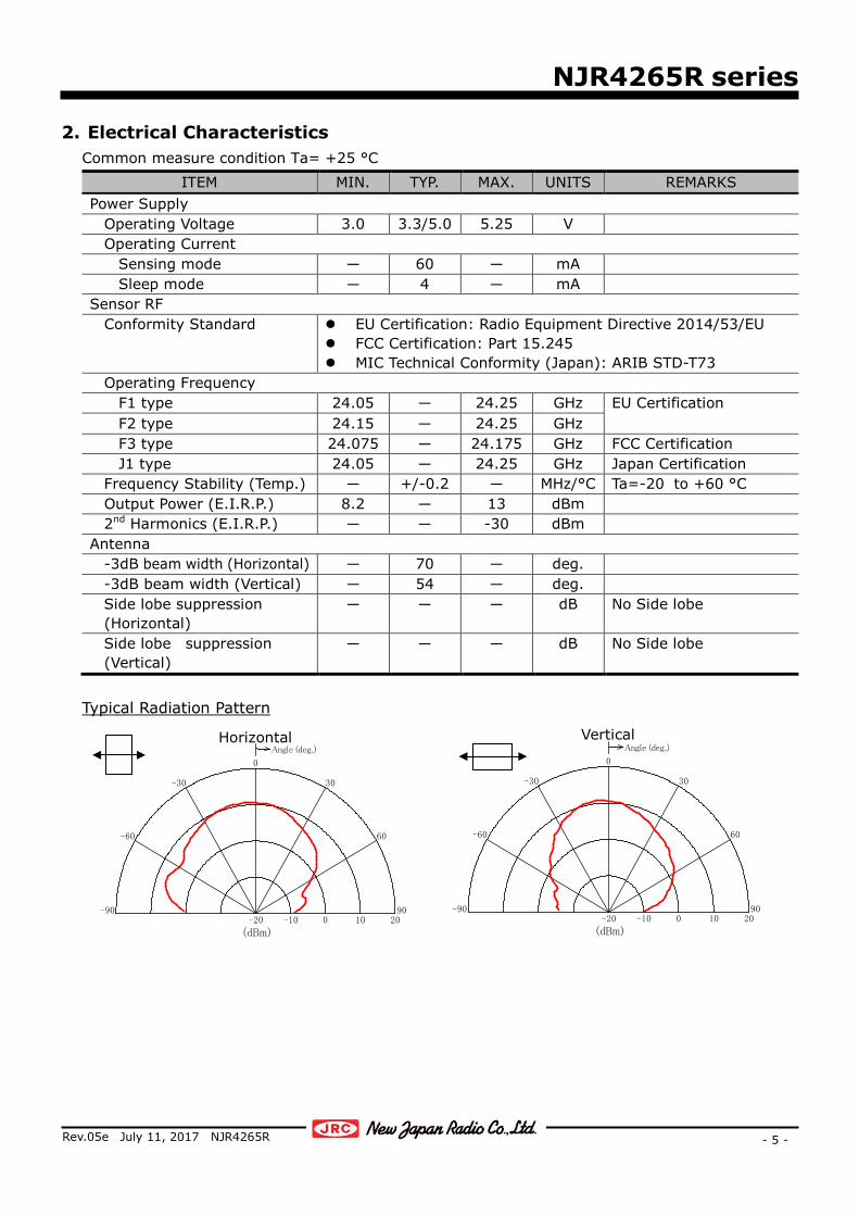
2. Electrical Characteristics Common measure condition Ta= +25 °C
ITEM MIN. TYP. MAX. UNITS REMARKS Power Supply
Operating Voltage 3.0 3.3/5.0 5.25 V Operating Current Sensing mode ― 60 ― mA Sleep mode ― 4 ― mA Sensor RF Conformity Standard EU Certification: Radio Equipment Directive 2014/53/EU
FCC Certification: Part 15.245 MIC Technical Conformity (Japan): ARIB STD-T73
Operating Frequency F1 type 24.05 ― 24.25 GHz EU Certification F2 type 24.15 ― 24.25 GHz F3 type 24.075 ― 24.175 GHz FCC Certification J1 type 24.05 ― 24.25 GHz Japan Certification Frequency Stability (Temp.) ― +/-0.2 ― MHz/°C Ta=-20 to +60 °C Output Power (E.I.R.P.) 8.2 ― 13 dBm 2nd Harmonics (E.I.R.P.) ― ― -30 dBm Antenna -3dB beam width (Horizontal) ― 70 ― deg. -3dB beam width (Vertical) ― 54 ― deg. Side lobe suppression
(Horizontal) ― ― ― dB No Side lobe
Side lobe suppression (Vertical)
― ― ― dB No Side lobe
Typical Radiation Pattern
20100-10-2090
60
30
0
-30
-60
-90
(dBm)
Angle (deg.)
20100-10-2090
60
30
0
-30
-60
-90
(dBm)
Angle (deg.)Horizontal Vertical

NJR4265R series
- 6 -
Rev.05e July 11, 2017 NJR4265R
3. Environmental characteristics ITEM SPECIFICATION
Operation Temperature -20 to +60 °C Storage Temperature -40 to +80 °C Humidity 0 to 95 % @+30 °C Vibration 49.03 m/s2 (5 G), 30 to 50 Hz, 10 minutes, XYZ direction Shock 196.13 m/s2 (20 G), Half sine, 11 ms, XYZ direction, 3 times
NJR4265R series
- 7 -
Rev.05e July 11, 2017 NJR4265R
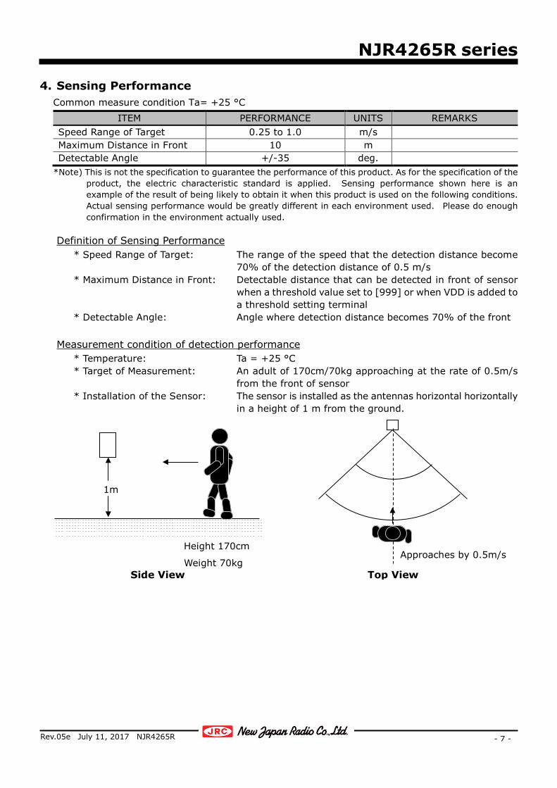
4. Sensing Performance Common measure condition Ta= +25 °C
ITEM PERFORMANCE UNITS REMARKS Speed Range of Target 0.25 to 1.0 m/s Maximum Distance in Front 10 m Detectable Angle +/-35 deg.
*Note) This is not the specification to guarantee the performance of this product. As for the specification of the product, the electric characteristic standard is applied. Sensing performance shown here is an example of the result of being likely to obtain it when this product is used on the following conditions. Actual sensing performance would be greatly different in each environment used. Please do enough confirmation in the environment actually used.
Definition of Sensing Performance
* Speed Range of Target: The range of the speed that the detection distance become 70% of the detection distance of 0.5 m/s
* Maximum Distance in Front: Detectable distance that can be detected in front of sensor when a threshold value set to [999] or when VDD is added to a threshold setting terminal
* Detectable Angle: Angle where detection distance becomes 70% of the front Measurement condition of detection performance
* Temperature: Ta = +25 °C * Target of Measurement: An adult of 170cm/70kg approaching at the rate of 0.5m/s
from the front of sensor * Installation of the Sensor: The sensor is installed as the antennas horizontal horizontally
in a height of 1 m from the ground.
1m
Height 170cm
Weight 70kg Top View
Approaches by 0.5m/s
Side View

NJR4265R series
- 8 -
Rev.05e July 11, 2017 NJR4265R
5. Signal processing for the steady sensing of moving object This product is embedding software for the steady sensing of moving object. It is enhance the signal from movement object of pedestrian etc. and is reduce random noise and sudden signal which caused an incorrect detection by using the signal from IQ mixer, namely Environmental Noise Reduction. The following effects are expectable. Reduction of false detection by random movement such as the shakes of plant by wind or the
noise of rain etc. Reduction of the false detection by sudden movement such as the insect etc. which cross just
before a sensor Steady detection of movement objects such as pedestrian under the environment where the
above-mentioned noise exists. Reduction of the mutual interference of sensors Identification of direction of movement (approach and leaving)
*Note) This signal processing function assumes the following noises are reduced, and pedestrian's movement is emphasized. However, it is likely to become a counter productivity for a signal outside assumption.

NJR4265R series
- 9 -
Rev.05e July 11, 2017 NJR4265R
6. Interface 6.1. Pin Assignment
Pin diagram (Bottom View)
# NAME I/O DESCRIPTION 1 Option ― Option Pin
Option pin is not assigned at NJR4265R. Keep it in electrically open state
2 TxD (UART) O UART TxD 3 RxD (UART) I UART RxD 4 Threshold Setting I Analog threshold voltage (VTH)
Available to set by the voltage applied to this pin. Threshold of detection distance = VTH / VDD x 10 m *Note1
5 Detect (approaching)
O Output for approaching detection *Note2 H: Detect / L: No detect
6 Detect (leaving)
O Output for leaving detection *Note2 H: Detect / L: No detect
7 VDD I Power Supply Input (VDD): 3.0 to 5.25 V 8 ― ― Internal connection *Note3
DO NOT connect any signal lines including GND. 9 ― ― 10 ― ― 11 GND ― GND Pin
*Note1) Detection distance assumes the case that an adult of 170cm/70kg approaches at the rate of 0.5m/s from the front.
*Note2) Pin 5 or 6 is changed to H level respectively when the movements of approaching or leaving is detected. (Output current < 5mA)
*Note3) Pin 8, 9 and10 are used for internal connection. Those must be electrically open independently. These pins must use the via holes of an independent pad when the sensor install on a PCB. Do not connect also between these terminals too.

NJR4265R series
- 10 -
Rev.05e July 11, 2017 NJR4265R
6.2. Asynchronous Serial Data Bus (UART) Interface
NJR4265R is able to control of sensor mode, set of threshold level, acquisition of detection result and acquisition of various information of sensor states from PC or MCU, etc. by using UART Interface.
ITEM FORMAT UNITS REMARKS Signal Level CMOS ― Internally pulled-up by 10 Kohms Communication Parameters Baud Rates 9600 bps Data Bits 8 bits Stop Bits 1 bits Parity odd ― Handshake non ― Byte Order LSB ―
NJR4265R series
- 11 -
Rev.05e July 11, 2017 NJR4265R
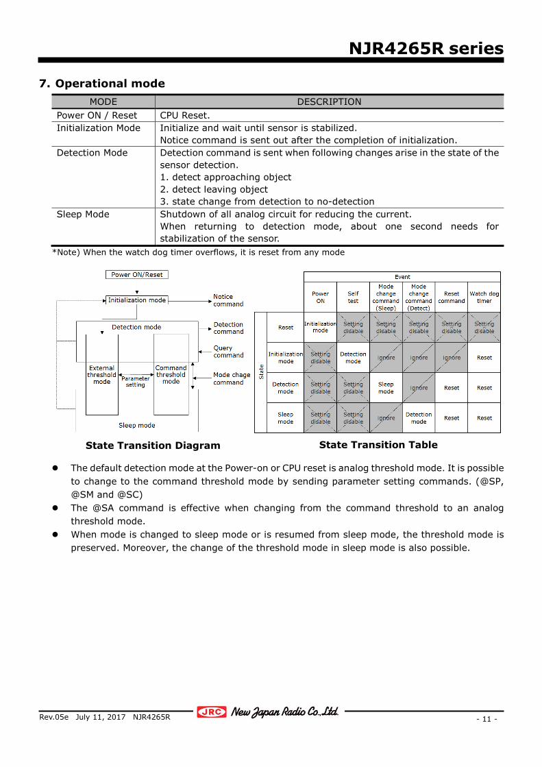
7. Operational mode MODE DESCRIPTION
Power ON / Reset CPU Reset. Initialization Mode Initialize and wait until sensor is stabilized.
Notice command is sent out after the completion of initialization. Detection Mode Detection command is sent when following changes arise in the state of the
sensor detection. 1. detect approaching object 2. detect leaving object 3. state change from detection to no-detection
Sleep Mode Shutdown of all analog circuit for reducing the current. When returning to detection mode, about one second needs for stabilization of the sensor.
*Note) When the watch dog timer overflows, it is reset from any mode
The default detection mode at the Power-on or CPU reset is analog threshold mode. It is possible to change to the command threshold mode by sending parameter setting commands. (@SP, @SM and @SC)
The @SA command is effective when changing from the command threshold to an analog threshold mode.
When mode is changed to sleep mode or is resumed from sleep mode, the threshold mode is preserved. Moreover, the change of the threshold mode in sleep mode is also possible.
State Transition Diagram State Transition Table
NJR4265R series
- 12 -
Rev.05e July 11, 2017 NJR4265R
8. Communication command 8.1. Outline
COMMAND TYPE DIRECTION DESCRIPTION EFFECTIVE MODE Detection Sensor to Host Sending from sensor when movement
is detected Detection mode
Mode Change Host to Sensor Change the sensor mode Detection mode Sleep mode Parameter Setting Host to Sensor Setting and change of threshold
parameters Query Sensor to Host
Host to Sensor Reading of state of sensor (mode , parameters)
Reset Host to Sensor Reset of sensor Start Notification Sensor to Host Sending from sensor when initialization
is completed Initialization
mode Error Response Sensor to Host Sending from sensor when error occurs All mode
8.2. Communication Command List
Both Sensor-to-Host (S-to-H) and Host-to-sensor (H-to-S) use the following formats. @ XXX xx <CR><LF>
@: Command header XXX: Command characters, alphabet 1-3 characters. (Capital letter and small letter
are Distinguished.) xx: Command/configuration parameters (numerical value or alphabet one
character or “?”.) <CR><LF>: Delimiter (CR+LF)
CONTENTS/EFFECTS XXX DIRECTION FORMAT REMARKS
Detection Commands Detected Approaching movement C S-to-H @C<CR><LF> Detected Leaving movement L S-to-H @L<CR><LF> Becomes undetected from detected N S-to-H @N<CR><LF>
Mode Change Commands Change to Detection mode T H-to-S @T<CR><LF> Change to Sleep mode U H-to-S @U<CR><LF>
Parameter Setting Commands Setting an Approaching threshold SP H-to-S @SPxxx<CR><LF> Setting a Leaving threshold SM H-to-S @SMxxx<CR><LF> Change to Analog threshold mode SA H-to-S @SA<CR><LF> Change to Command threshold mode SC H-to-S @SC<CR><LF>
Query Commands Acquire the present detection Q1 H-to-S @Q1?<CR><LF> Response of present detection S-to-H @C<CR><LF> Approaching
@L<CR><LF> Leaving @N<CR><LF> No detection
Acquire the present mode Q2 H-to-S @Q2?<CR><LF> Response of present mode S-to-H @T<CR><LF> Detection mode
@U<CR><LF> Sleep mode
NJR4265R series
- 13 -
Rev.05e July 11, 2017 NJR4265R
CONTENTS/EFFECTS XXX DIRECTION FORMAT REMARKS
Acquire the present threshold mode Q6 H-to-S @Q6?<CR><LF> Response of present threshold mode S-to-H @SA<CR><LF> Analog threshold
@SC<CR><LF> Command threshold Acquire the Approaching threshold SP H-to-S @SP?<CR><LF> Response of Approaching threshold S-to-H @SPxxx<CR><LF> *Note1 Acquire the Leaving threshold SM H-to-S @SM?<CR><LF> Response of Leaving threshold S-to-H @SMxxx<CR><LF> *Note1 Acquire the Analog threshold SV H-to-S @SV?<CR><LF> Response Analog threshold S-to-H @SVxxxx<CR><LF> Value of ADC Acquire the software version V H-to-S @V?<CR><LF> Response of software version S-to-H @Vx.xx<CR><LF> x.xx: Version
Reset Command, Start Notification Command Reset Command R H-to-S @R<CR><LF> Start Notification W S-to-H @W<CR><LF>
Error Response Commands Notification of UART framing error EF S-to-H @EF<CR><LF> Notification of UART parity error EP S-to-H @EP<CR><LF> Notification of Communication error ER S-to-H @EP<CR><LF> Notification of Self-test ES S-to-H @ER<CR><LF> Notification of watch dog timer error EW S-to-H @EW<CR><LF>
*Note1) Capable threshold setting range is Integer 1-999. The relation between the threshold value and the detection distance (*Note2) can be shown by the
following expressions: Da =SP/100, [Da] is approaching detection distance (units: m) Dl = SM/100, [Dl] is leaving detection distance (units: m) *Note2) Detection distance assumes the case that an adult of 170cm/70kg approaches at the rate of 0.5m/s
from the front.
NJR4265R series
- 14 -
Rev.05e July 11, 2017 NJR4265R
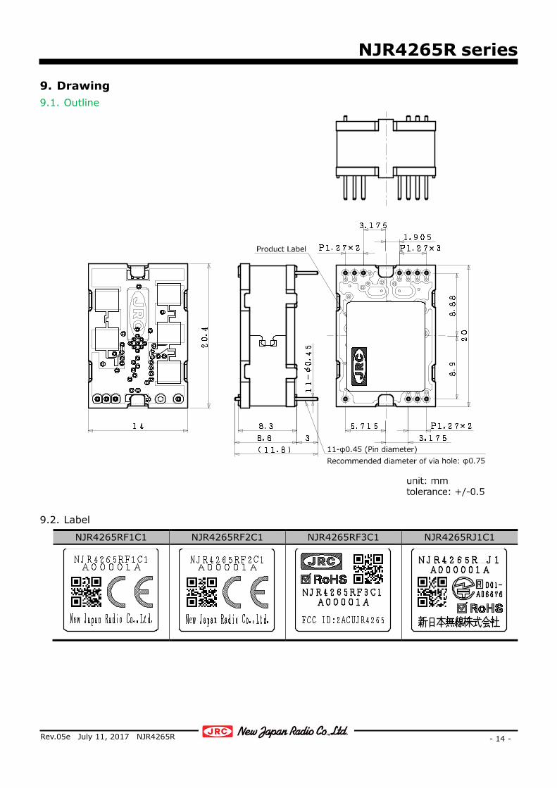
9. Drawing 9.1. Outline
9.2. Label
NJR4265RF1C1 NJR4265RF2C1 NJR4265RF3C1 NJR4265RJ1C1
NJR4265R series
- 15 -
Rev.05e July 11, 2017 NJR4265R
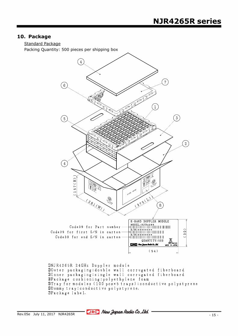
10. Package Standard Package Packing Quantity: 500 pieces per shipping box
NJR4265R series
- 16 -
Rev.05e July 11, 2017 NJR4265R
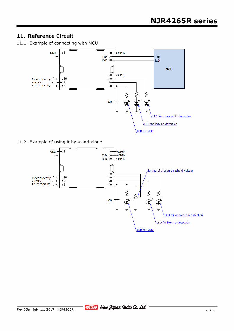
11. Reference Circuit 11.1. Example of connecting with MCU
11.2. Example of using it by stand-alone

NJR4265R series
- 17 -
Rev.05e July 11, 2017 NJR4265R
12. Recommendation Mounting Conditions 12.1. Footprint dimensions
*Note) In actual design, please optimize in accordance with the situation of your board design and soldering
condition.
12.2. Soldering conditions Soldering way: Solder iron *Note Solder iron temperature: 350 °C or less Mounting time: 3 second or less per pin *Note) The soldering iron to be used must be grounded via a resistance of about 1 MΩ.

NJR4265R series
- 18 -
Rev.05e July 11, 2017 NJR4265R
Caution
1. NJRC strives to produce reliable and high quality microwave components. NJRC's microwave components are intended for specific applications and require proper maintenance and handling. To enhance the performance and service of NJRC's microwave components, the devices, machinery or equipment into which they are integrated should undergo preventative maintenance and inspection at regularly scheduled intervals. Failure to properly maintain equipment and machinery incorporating these products can result in catastrophic system failures.
2. To ensure the highest levels of reliability, NJRC products must always be properly handled. The introduction
of external contaminants (e.g. dust, oil or cosmetics) can result in failures of microwave components. 3. NJRC offers a variety of microwave components intended for particular applications. It is important that you
select the proper component for your intended application. You may contact NJRC's sales office or sales representatives, if you are uncertain about the products listed in the catalog and the specification sheets.
4. Special care is required in designing devices, machinery or equipment, which demand high levels of
reliability. This is particularly important when designing critical components or systems whose foreseeable failure can result in situations that could adversely affect health or safety. In designing such critical devices, equipment or machinery, careful consideration should be given to, amongst other things, their safety design, fail-safe design, back-up and redundancy systems, and diffusion design.
5. The products listed in the catalog and specification sheets may not be appropriate for use in certain
equipment where reliability is critical or where the products may be subjected to extreme conditions. You should consult our sales office or sales representatives before using the products in any of the following types of equipment. * Aerospace Equipment * Equipment Used in the Deep Sea * Power Generator Control Equipment (nuclear, steam, hydraulic) * Life Maintenance Medical Equipment * Fire Alarm/Intruder Detector * Vehicle Control Equipment (automobile, airplane, railroad, ship, etc.) * Various Safety Equipment
6. NJRC's products have been designed and tested to function within controlled environmental conditions. Do
not use products under conditions that deviate from methods or applications specified in the catalog and specification sheets. Failure to employ NJRC's products in the proper applications can lead to deterioration, destruction or failure of the products. NJRC shall not be responsible for any bodily injury, fires or accidents, property damage or any consequential damages resulting from the misuse or misapplication of its products. PRODUCTS ARE SOLD WITHOUT WARRANTY OF ANY OF KIND, EITHER EXPRESS OR IMPLIED, INCLUDING BUT NOT LIMITED TO ANY IMPLIED WARRANTY OF MERCHANTABILITY OR FITNESS FOR A PARTICULAR PURPOSE.
7. The product specifications and descriptions listed in the catalog and specification sheets are subject to
change at any time, without notice.
New Japan Radio Co., Ltd. 1 / 2
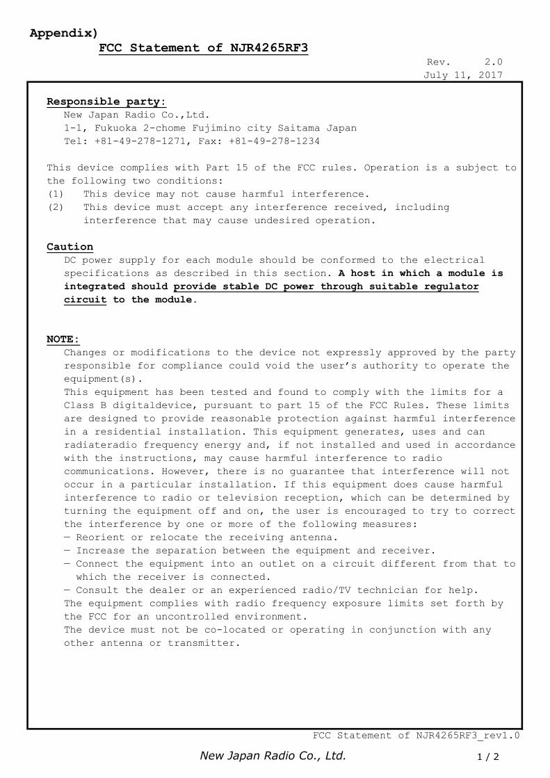
Appendix) FCC Statement of NJR4265RF3
Rev. 2.0July 11, 2017
Responsible party:New Japan Radio Co.,Ltd.1-1, Fukuoka 2-chome Fujimino city Saitama JapanTel: +81-49-278-1271, Fax: +81-49-278-1234
This device complies with Part 15 of the FCC rules. Operation is a subject tothe following two conditions:(1) This device may not cause harmful interference.(2) This device must accept any interference received, including interference that may cause undesired operation.
CautionDC power supply for each module should be conformed to the electrical specifications as described in this section. A host in which a module isintegrated should provide stable DC power through suitable regulatorcircuit to the module.
NOTE:Changes or modifications to the device not expressly approved by the party responsible for compliance could void the user’s authority to operate the equipment(s).This equipment has been tested and found to comply with the limits for a Class B digitaldevice, pursuant to part 15 of the FCC Rules. These limits are designed to provide reasonable protection against harmful interference in a residential installation. This equipment generates, uses and can radiateradio frequency energy and, if not installed and used in accordance with the instructions, may cause harmful interference to radio communications. However, there is no guarantee that interference will not occur in a particular installation. If this equipment does cause harmfulinterference to radio or television reception, which can be determined by turning the equipment off and on, the user is encouraged to try to correctthe interference by one or more of the following measures:— Reorient or relocate the receiving antenna.— Increase the separation between the equipment and receiver.— Connect the equipment into an outlet on a circuit different from that to which the receiver is connected.— Consult the dealer or an experienced radio/TV technician for help.The equipment complies with radio frequency exposure limits set forth by the FCC for an uncontrolled environment.The device must not be co-located or operating in conjunction with any other antenna or transmitter.
FCC Statement of NJR4265RF3_rev1.0

New Japan Radio Co., Ltd. 2 / 2
Appendix)
WARNING:The FCC regulations provide that changes or modifications not expressly approved by the party responsible for compliance could void the user’s authority to operate the equipment.
Limitation for use of the modules:When the module is installed in a host product, the module shall be connected directly to a PCB of the host product. It shall NOT be extended by any cable. DC power supply for each module must strictly be conformed to each electrical specification as described in the section 1 of thisdocument.
Manual and Product Labeling information to the End User:End user manual must include all required regulatory information and/or warning as show in this manual.OEM Integrator must indicate "Contain FCC ID: 2ACUJR4265" at the outsideof a host product such as label when the module is installed in the hostproduct.The following statement from FCC §15.19(a)(3) is required on the label of the host equipment.This device complies with Part 15 of the FCC Rules. Operation is subject to the following two conditions:(1) this device may not cause harmful interference, and (2) this device must accept any interference received, including interference that may cause undesired operation.OEM Integrator may be sure that the End user manual may not contain any information about the way to install or remove the modules from the host product.
APPLICABLE MODEL:This FCC Statement is valid only for the following model number:
NJR4265RF3C1
FCC Statement of NJR4265RF3_rev1.0


![p02 Sensor Resistif, Kapasitif Dan Induktif [Compatibility Mode]](https://img.dokumen.tips/doc/110x75/55cf9dd1550346d033af59bc/p02-sensor-resistif-kapasitif-dan-induktif-compatibility-mode.jpg)


![4 Prinsip Position Sensor [Compatibility Mode]](https://img.dokumen.tips/doc/110x75/577cd3df1a28ab9e7897aff4/4-prinsip-position-sensor-compatibility-mode.jpg)

