Embed Size (px)
Citation preview

Copyright Juniper, 2020 Version 1.0
Page 1 of 32 Juniper Networks Public Material – May be reproduced only in its original entirety (without revision).
Juniper Networks
EX2300, EX2300-C and EX3400 Ethernet Switches
Firmware: Junos OS 19.1R2
Non-Proprietary FIPS 140-2 Cryptographic Module Security Policy
Document Version: 1.0
Date: November 10, 2020
Juniper Networks, Inc. 1133 Innovation Way Sunnyvale, California 94089 USA 408.745.2000 1.888 JUNIPER www.juniper.net

Copyright Juniper, 2020 Version 1.0
Page 2 of 32 Juniper Networks Public Material – May be reproduced only in its original entirety (without revision).
Contents 1 Introduction .......................................................................................................................................... 4
1.1 Hardware and Physical Cryptographic Boundary .......................................................................... 6
1.2 Modes of Operation .................................................................................................................... 11
1.2.1 FIPS Approved Mode .................................................................................................................. 11
1.2.2 Non-Approved Mode ................................................................................................................. 12
1.3 Zeroization................................................................................................................................... 12
2 Cryptographic Functionality ................................................................................................................ 14
2.1 Allowed Algorithms and Protocols .............................................................................................. 14
2.2 Disallowed Algorithms and Protocols ................................................................................................ 17
2.3 Critical Security Parameters .............................................................................................................. 18
3 Roles, Authentication and Services ..................................................................................................... 20
3.1 Roles and Authentication of Operators to Roles.......................................................................... 20
3.2 Authentication Methods ............................................................................................................. 20
3.3 Services ....................................................................................................................................... 21
3.4 Non-Approved Services ............................................................................................................... 23
4 Self-tests.............................................................................................................................................. 24
5 Physical Security Policy ........................................................................................................................ 26
6 Security Rules and Guidance ............................................................................................................... 27
6.1 Cryptographic-Officer Guidance ................................................................................................. 28
6.1.1 Installing the FIPS-Approved firmware image ........................................................................... 28
6.1.2 Enabling FIPS-Approved Mode of Operation ...................................................................... 28
6.1.3 Placing the Module in a Non-Approved Mode of Operation .............................................. 30
6.2 User Guidance ............................................................................................................................. 30
7 References and Definitions ................................................................................................................. 31

Copyright Juniper, 2020 Version 1.0
Page 3 of 32 Juniper Networks Public Material – May be reproduced only in its original entirety (without revision).
List of Tables Table 1 – EX2300, EX2300-C and EX3400 Ethernet Switches Configurations ............................................. 5
Table 2 – Security Level of Security Requirements ..................................................................................... 5
Table 3 – Ports and Interfaces ..................................................................................................................... 9
Table 4 – Kernel Approved Cryptographic Functions ................................................................................ 14
Table 5 – LibMD Approved Cryptographic Functions ................................................................................ 14
Table 6 – OpenSSL Approved Cryptographic Functions ............................................................................ 14
Table 7 – Allowed Cryptographic Functions .............................................................................................. 16
Table 8 – Protocols Allowed in FIPS Mode ................................................................................................ 16
Table 9 – Critical Security Parameters (CSPs) ............................................................................................ 18
Table 10 – Public Keys ................................................................................................................................ 18
Table 11 – Authenticated Services ............................................................................................................. 21
Table 12 – Unauthenticated Services ........................................................................................................ 21
Table 13 – CSP Access Rights within Services ............................................................................................ 22
Table 14 – Authenticated Services ............................................................................................................. 23
Table 15 – Unauthenticated Services ........................................................................................................ 23
Table 16 – References ................................................................................................................................ 31
Table 17 – Acronyms and Definitions ........................................................................................................ 31
Table 18 – EX Switches Hardware Guides ................................................................................................. 32
List of Figures Figure 1 – EX2300-C-12T/12P ....................................................................................................................... 6
Figure 2 – Front Panel EX2300-24P/24T ...................................................................................................... 6
Figure 3 – Rear Panel EX2300-C-12T/12P .................................................................................................... 6
Figure 4 – Rear Panel EX2300-24P/24T ....................................................................................................... 7
Figure 5 – Front Panel EX2300-48P/48T ...................................................................................................... 7
Figure 6 – Rear Panel EX2300-48P/48T ....................................................................................................... 7
Figure 7 – Front Panel EX3400-24P/24T ...................................................................................................... 8
Figure 8 – Front Panel EX3400-48P/48T ...................................................................................................... 8
Figure 9 – Rear Panel EX3400-24P/24T/48P/48T ........................................................................................ 8

Copyright Juniper, 2020 Version 1.0
Page 4 of 32 Juniper Networks Public Material – May be reproduced only in its original entirety (without revision).
1 Introduction
EX2300 and EX2300-C Ethernet Switches deliver a compact, high-density, cost-effective solution for small network environments where space and power are at a premium. Featuring a small, 1U footprint, the EX2300 and EX2300-C are ideal for access-layer deployments in micro branches, retail and workgroup environments, and converged network access in larger networks. The EX2300 offers 24 10/100/1000BASE-T ports in a single platform, while the EX2300-C offers 12 10/100/1000BASE-T ports. Both models are available with or without IEEE 802.3af Power over Ethernet (PoE) or 802.3at PoE+ for powering attached network devices. Optional front panel 10GbE uplink ports support connections to higher-layer devices. EX3400 Ethernet Switches are a cost-effective solution for today’s most demanding converged data, voice, and video enterprise access networks. The compact, fixed configuration 1U devices offer levels of performance and management previously available only with high-end access switches. Featuring models offering either 24 or 48 10/100/1000BASE-T ports, the EX3400 switches also support IEEE 802.3af Power over Ethernet (PoE) or 802.3at PoE+ for powering networked telephones, video cameras, wireless LAN access points, and other IP devices. Four front-panel dual-mode (GbE/10GbE) SFP/SFP+ uplink ports and two 40GbE QSFP+ ports are also available for connecting the switches to upstream devices.
1.1 Module Overview
This is a non-proprietary Cryptographic Module Security Policy for the Juniper Networks EX2300, EX2300-C and EX3400 Ethernet Switches Cryptographic Module from Juniper Networks. It provides detailed information relating to each of the FIPS 140-2 security requirements relevant to the Juniper Networks EX2300, EX2300-C and EX3400 Ethernet Switches Cryptographic Module along with instructions on how to run the module in a secure FIPS 140-2 mode. The cryptographic module provides for an encrypted connection, using SSH, between the management console and the switches. All other data input or output from the switches is considered plaintext for this FIPS 140-2 validation. The EX switches run JUNOS. The validated version of JUNOS OS is 19.1R2; the image for the EX2300, EX2300-C and EX3400 Ethernet Switches hardware platforms is: junos-arm-32-19.1R2.5.tgz. The Juniper Networks EX2300, EX2300-C and EX3400 Ethernet Switches are cryptographic modules that are defined as multi-chip standalone modules that execute JUNOS OS 19.1R2 firmware on the EX2300, EX2300-C and EX3400 Ethernet Switches listed in Table 1. The cryptographic boundaries for the EX2300, EX2300-C and EX3400 Ethernet Switches are defined as the outer edge of each switch. The cryptographic modules’ operational environment is a limited operational environment. Table 1 gives a list of the hardware versions that are part of the module validation and the basic configuration of the hardware.

Copyright Juniper, 2020 Version 1.0
Page 5 of 32 Juniper Networks Public Material – May be reproduced only in its original entirety (without revision).
Table 1 – EX2300, EX2300-C and EX3400 Ethernet Switches Configurations
Models Hardware Versions Processor RAM Ethernet Ports (10/100/1000 BASE-T GbE ports,
10GbE uplink ports) EX2300 EX2300-C-12P, EX2300-C-12T
1.25GHz ARM Cortex A9
2GB DDR 12, 2
EX2300-24P, EX2300-24T 24, 4
EX2300-48P, EX2300-48T 48, 4
EX3400 EX3400-24P, EX3400-24T Dual Core 1 GHz ARM Cortex A9
2GB DDR
with ECC
24, 4
EX3400-48P, EX3400-48T 48, 4
The cryptographic modules meet the overall requirements applicable to Level 1 security of FIPS 140-2. The following table lists the level of validation for each area in FIPS 140-2:
Table 2 – Security Level of Security Requirements
Area Description Level
1 Module Specification 1
2 Ports and Interfaces 1
3
Roles, Services, and Authentication
3
4 Finite State Model 1
5 Physical Security 1
6 Operational Environment N/A
7 Key Management 1
8 EMI/EMC 1
9 Self-test 1
10 Design Assurance 3
11 Mitigation of Other Attacks N/A
Overall 1 The modules have a limited operational environment as per the FIPS 140-2 definitions. It includes a firmware load service to support necessary updates. New firmware versions within the scope of this validation must be validated through the FIPS 140-2 CMVP. Any other firmware loaded into the modules are out of the scope of this validation and require a separate FIPS 140-2 validation.
The modules do not implement any mitigations of other attacks as defined by FIPS 140-2.

Copyright Juniper, 2020 Version 1.0
Page 6 of 32 Juniper Networks Public Material – May be reproduced only in its original entirety (without revision).
1.1 Hardware and Physical Cryptographic Boundary
The physical forms of the module’s various models are depicted in Figures 1-6 below. For all models, the cryptographic boundary is defined as the outer edge of the chassis. The modules exclude the power supplies from the requirements of FIPS 140-2. The power supplies do not contain any security relevant components and cannot affect the security of the module.
Figure 1 – EX2300-C-12T/12P
Figure 2 – Front Panel EX2300-24P/24T
Figure 3 – Rear Panel EX2300-C-12T/12P
1. CLEI code label
2. Serial number ID label
3. Protective earthing terminal
4. AC power cord inlet

Copyright Juniper, 2020 Version 1.0
Page 7 of 32 Juniper Networks Public Material – May be reproduced only in its original entirety (without revision).
Figure 4 – Rear Panel EX2300-24P/24T
1. USB port
2. Management Ethernet port
3. RJ-45 console port
4. Protective earthing terminal
5. ESD point
6. Air exhaust openings
7. Serial number ID label
8. CLEI code label
9. AC power cord inlet
Figure 5 – Front Panel EX2300-48P/48T
Figure 6 – Rear Panel EX2300-48P/48T
1. USB port
2. Management Ethernet port
3. RJ-45 console port
4. Protective earthing terminal
5. ESD point
6. Air exhaust openings
7. Serial number ID label
8. CLEI code label
9. AC power cord inlet

Copyright Juniper, 2020 Version 1.0
Page 8 of 32 Juniper Networks Public Material – May be reproduced only in its original entirety (without revision).
Figure 7 – Front Panel EX3400-24P/24T
Figure 8 – Front Panel EX3400-48P/48T
Figure 9 – Rear Panel EX3400-24P/24T/48P/48T
1 USB port
2 Management Ethernet port
3 RJ-45 console port
4 Protective earthing terminal
5 QSFP+ uplink ports
6 ESD point
7 Fan modules
8 AC power supply
9 Empty slot for power supply covered
by a blank panel
The cryptographic module supports the physical ports and corresponding logical interfaces identified
below. The flow of the data, control and status through the interfaces is controlled by the cryptographic
module. The interfaces can be categorized into the following logical interfaces defined by FIPS 140-2:
• Data Input Interface
• Data Out Interface
• Control Input Interface
• Status Output Interface
• Power Interface
The physical ports can be mapped to the logical interfaces. The mapping of the logical interfaces to the physical ports is shown in the following table:

Copyright Juniper, 2020 Version 1.0
Page 9 of 32 Juniper Networks Public Material – May be reproduced only in its original entirety (without revision).
Table 3 – Ports and Interfaces
Port Device (# of ports) Description Logical Interface Type
Ethernet (PFE) (data)
EX2300/ EX2300-C:
10/100/1000 BASE-T
Gigabit Ethernet ports:
EX2300-24T(24), EX2300-
24P(24), EX2300-48T(48),
EX2300-48P(48), EX2300-C-
12T(12), EX2300-C-12P(12)
10GbE small form-factor
pluggable transceiver (SFP/
SFP+) uplink ports:
EX2300-24T(4), EX2300-
24P(4), EX2300-48T(4),
EX2300-48P(4), EX2300-C-
12T (12), EX2300-C-12P (12)
EX3400:
10/100/1000 BASE-T
Gigabit Ethernet ports:
EX3400-24T(4), EX3400-
24P(4), EX3400-48T(4),
EX3400-48P(4)
Dual-mode (GbE/10GbE)
small form-factor pluggable
transceiver (SFP/ SFP+)
uplink ports:
EX3400-24T(4), EX3400-
24P(4), EX3400-48T(4),
EX3400-48P(4)
40GbE QSFP+ ports:
EX3400-24T(2), EX3400-
24P(2), EX3400-48T(2),
LAN Communications
Control in, Data in, Status out, Data out

Copyright Juniper, 2020 Version 1.0
Page 10 of 32 Juniper Networks Public Material – May be reproduced only in its original entirety (without revision).
EX3400-48P(2)
Ethernet (mgmt.) EX2300-24T(1), EX2300-
24P(1), EX2300-48T(1),
EX2300-48P(1), EX2300-C-
12T(1), EX2300-C-12P(1),
EX3400-24T(1), EX3400-
24P(1), EX3400-48T(1),
EX3400-48P(1)
Remote Management
Control in, Data in, Status out, Data out
Serial EX2300-24T(1), EX2300-
24P(1), EX2300-48T(1),
EX2300-48P(1), EX2300-C-
12T(1), EX2300-C-12P(1),
EX3400-24T(1), EX3400-
24P(1), EX3400-48T(1),
EX3400-48P(1)
Console serial port Control in, Data in, Status out, Data out
Power EX2300-24T(1), EX2300-
24P(1), EX2300-48T(1),
EX2300-48P(1), EX2300-C-
12T(1), EX2300-C-12P(1),
EX3400-24T(2), EX3400-
24P(2), EX3400-48T(2),
EX3400-48P(2)
Power connector Power input, Power over Ethernet
Reset Button EX2300-24T(1), EX2300-
24P(1), EX2300-48T(1),
EX2300-48P(1), EX2300-C-
12T(1), EX2300-C-12P(1),
EX3400-24T(1), EX3400-
24P(1), EX3400-48T(1),
EX3400-48P(1)
Reset Control in

Copyright Juniper, 2020 Version 1.0
Page 11 of 32 Juniper Networks Public Material – May be reproduced only in its original entirety (without revision).
LEDs EX2300-24T(6), EX2300-
24P(7), EX2300-48T(6),
EX2300-48P(7), EX2300-C-
12T(7), EX2300-C-12P(7),
EX3400-24T(3), EX3400-
24P(3), EX3400-48T(3),
EX3400-48P(3)
Status indicator lighting
Status out
USB EX2300-24T(1), EX2300-
24P(1), EX2300-48T(1),
EX2300-48P(1), EX2300-C-
12T(1), EX2300-C-12P(1),
EX3400-24T(1), EX3400-
24P(1), EX3400-48T(1),
EX3400-48P(1)
Console mini-USB port
Load Junos Image
Control in, Data in
EX2300-24T(0), EX2300-
24P(0), EX2300-48T(0),
EX2300-48P(0), EX2300-C-
12T(1), EX2300-C-12P(1),
EX3400-24T(0), EX3400-
24P(0), EX3400-48T(0),
EX3400-48P(0)
USB Type A
Load Junos Image
Control In, Data in
The flow of input and output of data, control, and status is managed by the cryptographic module.
Details of each model’s hardware are available in the guides listed in Table 18.
1.2 Modes of Operation
The module supports one FIPS Approved mode of operation and a non-Approved mode of operation. The
module must always be zeroized when switching between a FIPS Approved mode of operation and the
non-Approved mode of operation and vice versa.
1.2.1 FIPS Approved Mode
The EX switches with Junos OS 19.1R2 installed, contain one FIPS-Approved mode of operation and a non-Approved mode of operation. The Junos OS 19.1R2 firmware image must be installed on the devices. The modules are configured during initialization to operate in the approved mode or the non-approved mode. The cryptographic officer can configure the module to run in a FIPS Approved mode of operation by
following the instructions in the crypto-officer guidance (section 6.1).
Copyright Juniper, 2020 Version 1.0
Page 12 of 32 Juniper Networks Public Material – May be reproduced only in its original entirety (without revision).
The Crypto-Officer can verify that the cryptographic module is in an Approved mode by observing the console prompt and running the “show version local” command. When operating in FIPS mode, the prompt will read “<user>@<device name>:fips#” (e.g. crypto-officer@EX2300:fips#). The “show version local” command will allow the Crypto-Officer to verify that the validated firmware version is running on the module. The Crypto-Officer can also use the “show system fips level” command to determine if the module is operating in FIPS mode.
1.2.2 Non-Approved Mode
The cryptographic module supports a non-Approved mode of operation. When operated in the non- Approved mode of operation, the module supports the algorithms identified in Section 2.2 as well as the algorithms supported in the Approved mode of operation. The Crypto-Officer can place the module into a non-approved mode of operation by following the
instructions in the crypto-officer guidance (section 6.1).
1.3 Zeroization
The cryptographic module provides a non-Approved mode of operation in which non-Approved cryptographic algorithms are supported. When transitioning between the non-Approved mode of operation and the FIPS-Approved mode of operation, or vice-versa, the cryptographic officer shall zeroize all keys and CSPs. Zeroization completely erases all configuration information on the EX2300/EX2300-C/EX3400. The Crypto Officer initiates the zeroization process by entering the “request system zeroize” operational command from the CLI after enabling FIPS mode. Use of this command is restricted to the Crypto Officer (To zeroize the system before enabling FIPS mode, use the “request system zeroize media” command.)
Use of the zeroize command is restricted to the Cryptographic Officer. The cryptographic officer shall
perform zeroization in the following situations:
1. Before FIPS Operation: To prepare the device for operation as a FIPS cryptographic module by erasing all CSPs and other user-created data on a device before its operation as a FIPS cryptographic module.
2. Before non-FIPS Operation: To conduct erasure of all CSPs and other user-created data on a device in preparation for repurposing the device for non-FIPS operation.
CAUTION: Perform system zeroization with care. After the zeroization process is complete, no data is left
on the Routing Engine. The switch is returned to the factory default state, without any configured users
or configuration files.
To zeroize your switch: 1. From the CLI, enter root@switch> request system zeroize warning: System will be rebooted and may not boot without configuration

Copyright Juniper, 2020 Version 1.0
Page 13 of 32 Juniper Networks Public Material – May be reproduced only in its original entirety (without revision).
Erase all data, including configuration and log files? [yes, no] (no) 2. To initiate the zeroization process, type yes at the prompt: Erase all data, including configuration and log files? [yes, no] (no) yes 3. When the system finishes rebooting the system will be in a factory default state.
Note: The Cryptographic Officer must retain control of the module while zeroization is in process.
Note: In case the system does not boot-up correctly post zeroization and instead enters a continual boot
loop, a USB bootable image can be used to recover the system from this condition.
Copyright Juniper, 2020 Version 1.0
Page 14 of 32 Juniper Networks Public Material – May be reproduced only in its original entirety (without revision).
2 Cryptographic Functionality
2.1 Allowed Algorithms and Protocols
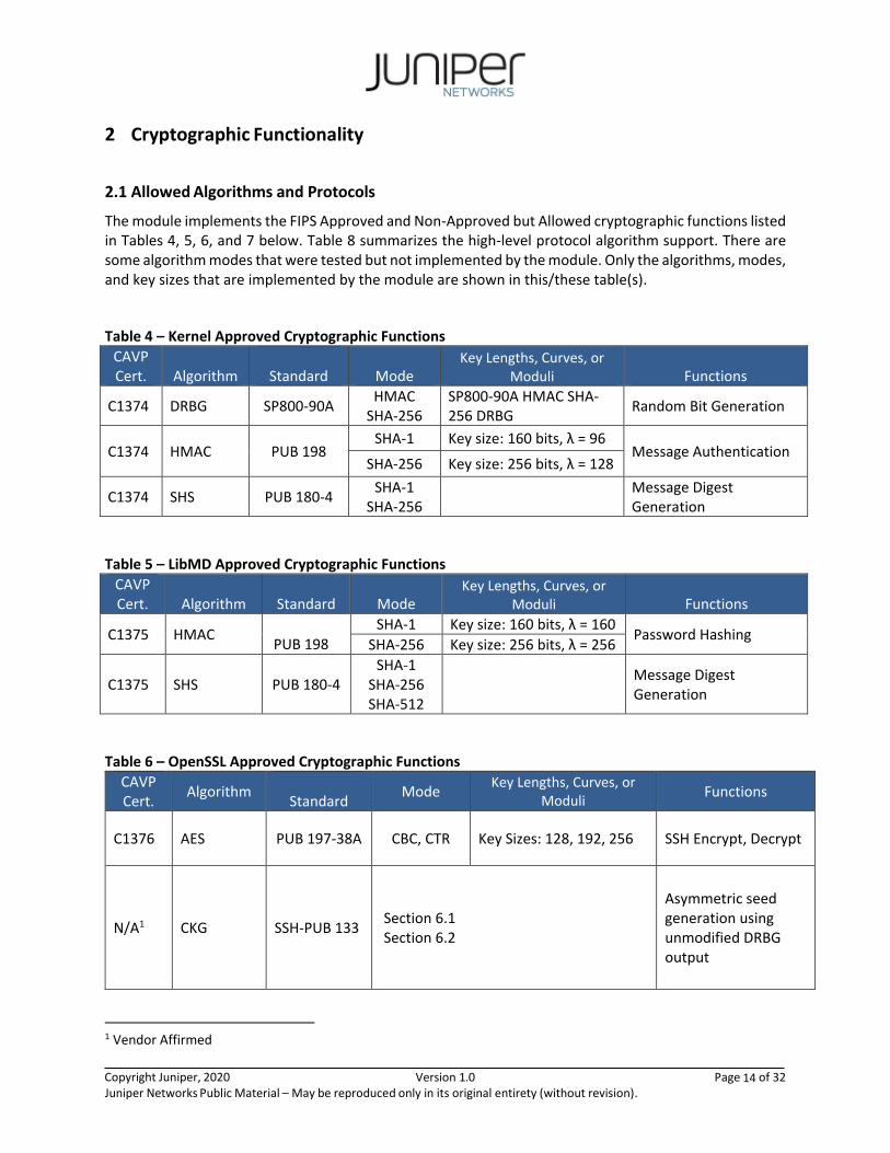
The module implements the FIPS Approved and Non-Approved but Allowed cryptographic functions listed in Tables 4, 5, 6, and 7 below. Table 8 summarizes the high-level protocol algorithm support. There are some algorithm modes that were tested but not implemented by the module. Only the algorithms, modes, and key sizes that are implemented by the module are shown in this/these table(s).
Table 4 – Kernel Approved Cryptographic Functions
CAVP Cert. Algorithm
Standard Mode
Key Lengths, Curves, or Moduli Functions
C1374 DRBG SP800-90A HMAC
SHA-256 SP800-90A HMAC SHA-256 DRBG
Random Bit Generation
C1374 HMAC PUB 198 SHA-1 Key size: 160 bits, λ = 96
Message Authentication SHA-256 Key size: 256 bits, λ = 128
C1374 SHS PUB 180-4 SHA-1
SHA-256
Message Digest Generation
Table 5 – LibMD Approved Cryptographic Functions
CAVP Cert. Algorithm Standard Mode
Key Lengths, Curves, or Moduli Functions
C1375 HMAC
PUB 198 SHA-1 Key size: 160 bits, λ = 160
Password Hashing SHA-256 Key size: 256 bits, λ = 256
C1375 SHS PUB 180-4 SHA-1
SHA-256 SHA-512
Message Digest Generation
Table 6 – OpenSSL Approved Cryptographic Functions
CAVP Cert.
Algorithm
Standard Mode
Key Lengths, Curves, or Moduli
Functions
C1376 AES PUB 197-38A CBC, CTR Key Sizes: 128, 192, 256 SSH Encrypt, Decrypt
N/A1 CKG SSH-PUB 133 Section 6.1 Section 6.2
Asymmetric seed generation using unmodified DRBG output
1 Vendor Affirmed

Copyright Juniper, 2020 Version 1.0
Page 15 of 32 Juniper Networks Public Material – May be reproduced only in its original entirety (without revision).
C1376 CVL (SSH KDF)
SP 800-135 SSHv2 Key Sizes: 128, 192, 2562 SSH Key Derivation
C1376 DRBG SP 800-90A HMAC SHA-256 Random Bit Generation
C1376 ECDSA PUB 186-4 P-256 (SHA 256) P-384 (SHA 384) P-521 (SHA 512)
SSH KeyGen, KeyVer, SigVer, SigGen
C1376 KTS
AES Cert. # C1376 and HMAC Cert. # C1376
Key establishment methodology provides between 128 and 256 bits of encryption strength
Triple-DES Cert. # C1376and HMAC Cert. # C1376
Key establishment methodology provides 112 bits of encryption strength
C1376 HMAC PUB 198
SHA-1 Key size: 160 bits, λ = 160
SSH Message Authentication
SHA-384 Key size: 384 bits, λ = 384
SHA-512 Key size: 512 bits, λ = 512
SHA-256
Key size: 256, bits, λ = 256
SSH Message Authentication, DRBG Primitive
C1376 SHS
PUB 180-4
SHA-1 SHA-256 SHA-384 SHA-512
Hash for HMAC, Sig Gen, Sig Ver
C1376 Triple-DES SP 800-67 TCBC Key Sizes: 168 Key Strength: 112
SSH Encrypt, Decrypt
C1376 RSA PUB 186-4
n=2048 n=3072
KeyGen
PKCS1.5
n=2048 (SHA-256, SHA-512) n=3072 (SHA-256, SHA-512) n=4096 (SHA-256, SHA-512)
SigGen3, SigVer4
2 The strength of the SSH KDF is the minimum of the Key Agreement method and the HMAC used. 3 RSA 186-2 4096 SigGen has been tested by the CAVP and is Approved for use per CMVP guidance, because testing for RSA 186-4 4096 SigGen was not available at the time of validation.
4 RSA 4096 SigVer was not tested by the CAVP; however, it is Approved for use per CMVP guidance, because RSA 2048 SigVer was tested and testing for RSA 4096 SigVer is not available.

Copyright Juniper, 2020 Version 1.0
Page 16 of 32 Juniper Networks Public Material – May be reproduced only in its original entirety (without revision).
N/A5 KAS-SSC SP 800- 56Arev3
ECDH P-256 (SHA 256) P-384 (SHA 384) P-521 (SHA 512)
Key Agreement Scheme - Key Agreement Scheme Shared Secret Computation (KAS-SSC) per SP 800-56Arev3, Key Derivation per SP 800-135 (CVL Cert. #C1376)
The cryptographic module also supports the following non-Approved algorithms, which are allowed for use in FIPS mode:
Table 7 – Allowed Cryptographic Functions
Algorithm Caveat Use
NDRNG [IG] 7.14 Scenario 1a
Provides 256 bits of security for the EX2300/EX2300 C and 192 bits of security for the EX3400.
Seeding the HMAC-DRBG
Table 8 – Protocols Allowed in FIPS Mode
Protocol Key Exchange Key Derivation Auth Cipher Integrity
SSHv26 EC Diffie-Hellman P-256, P-384, P-521
KDF (SHA-256,
SHA-384, SHA-
512)
Host Authentication: ECDSA P-256 with SHA-256 RSA 2048, 4096
Triple-DES CBC
AES CBC
128/192/256
AES CTR
128/192/256
HMAC-SHA-1
HMAC-SHA-256
HMAC-SHA-512
Client Authentication (optional):
ECDSA P-256 with SHA-256, P-384 with SHA-384, P-521 with SHA-512
RSA 2048, 4096
The cryptographic module supports the commercially available SSHv2 protocol. No parts of this
5 Vendor Affirmed per IG D.1rev3 (per IG D.8 Scenario X1).
6 RFC 4253 governs the generation of the Triple-DES encryption key for use with the SSHv2 protocol

Copyright Juniper, 2020 Version 1.0
Page 17 of 32 Juniper Networks Public Material – May be reproduced only in its original entirety (without revision).
protocol, other than the KDF, have been tested by the CAVP and CMVP. The SSH algorithms allow independent selection of key exchange, authentication, cipher and integrity. In Table 8 above, each column of options for a given protocol is independent and may be used in any viable combination.
2.2 Disallowed Algorithms and Protocols
The non-Approved mode of operation supports the same algorithms that are supported in the Approved
mode of operation; however, the non-Approved mode of operation supports plaintext protocols.
The module supports the following non-Approved and non-Compliant algorithms when it is configured in the non-FIPS Approved mode:
Algorithms
• ARCFOUR
• AES-GCM (non-compliant)
• Blowfish
• CAST
• ChaCha20
• DSA (non-compliant)
• Diffie-Hellman (non-compliant)
• EC Diffie-Hellman (ed25519)
• ECDSA (ed25519)
• HMAC-MD5
• HMAC-SHA1-96
• MD5
• Poly1305
• RIPEMD160
• RSA with key size less than 2048
• UMAC
Protocols
• finger
• ftp
• rlogin
• telnet
• tftp
• rsh

Copyright Juniper, 2020 Version 1.0
Page 18 of 32 Juniper Networks Public Material – May be reproduced only in its original entirety (without revision).
2.3 Critical Security Parameters
All CSPs and public keys used by the module are described in this section.
Table 9 – Critical Security Parameters (CSPs)
Name Description and usage
DRBG_Seed Seed material used to seed or reseed the DRBG
DRBG_State Values V and Key which comprise the HMAC_DRBG state
Entropy Input String
256 bits entropy (min) input used to instantiate the DRBG
ECDH Shared Secret
The shared secret used in Elliptic Curve Diffie Hellman (ECDH) key exchange. 256, 384 or 521 bits. Established per the Elliptic Curve Diffie-Hellman key agreement.
SSH PHK SSH Private host key. 1st time SSH is configured, the key is generated. RSA 2048,4096, ECDSA P-256. Used to identify the host.
SSH ECDH Ephemeral EC Diffie-Hellman private key used in SSH. ECDH P-256, P-384, or P-521
SSH-SEKs SSH Session Keys: Session keys used with SSH-2, TDES-CBC (3 key), AES-CBC/CTR 128, 192, 256, HMAC-SHA-512, HMAC-SHA-256, HMAC-SHA-1 key (160)
HMAC Key The LibMD HMAC keys: message digest for hashing password and critical function test.
User Password Passwords used to authenticate Users to the module (Stored Salted and hashed with SHA-1, SHA-256, or SHA-512).
CO Password Passwords used to authenticate COs to the module (Stored Salted and hashed with SHA-1,
SHA-256, or SHA-512).
Table 10 – Public Keys
Name D Description and usage
SSH-PUB SSH Public Host Key used to identify the host. RSA 2048, 4096, ECDSA P-256.
SSH-ECDH-PUB Ephemeral EC Diffie-Hellman public key used in SSH key establishment. ECDH P-256, P-384, or P-521
Auth-User Pub User Authentication Public Keys. Used to authenticate users to the module. ECDSA P-256, P-384 or P-521 or RSA 2048, 4096 384, or P-521
Auth-CO Pub
CO Authentication Public Keys. Used to authenticate CO to the module. ECDSA P-256, P-384, or P-521 or RSA 2048, 4096 or P-521 JuniperRootCA The Junos OS uses four-level certificate hierarchies for firmware signature validation. At the root of the chain of trust is a self-signed certificate
authority (CA) known as the JuiperRootCA which uses ECDSA-256/SHA-256. It is used to sign the EngineeringCA.
EngineeringCA The EngineeringCA which uses ECDSA P-256 w/ SHA-256 X.509 certificate and is used to sign the PackageCA.

Copyright Juniper, 2020 Version 1.0
Page 19 of 32 Juniper Networks Public Material – May be reproduced only in its original entirety (without revision).
PackageCA
The PackageCA which uses ECDSA P-256 w/ SHA-256 X.509 Certificate and is used to sign the PackageProduction public/private key pair.
PackageProduction ECDSA P-256 w/ SHA-256 X.509 certificate; Certificate that holds the public key of the signing key that was used to generate all the signatures used on the packages and signature lists.

Copyright Juniper, 2020 Version 1.0
Page 20 of 32 Juniper Networks Public Material – May be reproduced only in its original entirety (without revision).
3 Roles, Authentication and Services
3.1 Roles and Authentication of Operators to Roles
The module supports two operator roles: Cryptographic Officer (CO) and User. The module supports concurrent operators but does not support a maintenance role and/or bypass capability. The module enforces the separation of roles using identity-based operator authentication.
The Cryptographic Officer role configures and monitors the module via a console or SSH connection. As
root or super-user, the Cryptographic Officer has permission to view and edit secrets within the module.
Descriptions of the services available to the Crypto-Officer role are provided in Table 11.
The User role accesses the module’s cryptographic services that include monitoring the EX Switch via the
console or SSH. The User role cannot change the configuration. Table 11 lists the services available to
the User Role.
3.2 Authentication Methods
The module implements two forms of Identity-Based authentication, username and password over the
console and SSH as well as username and ECDSA or RSA public key over SSH.
Password authentication: The module enforces 10-character passwords (at minimum) chosen from the
96 human readable ASCII characters. The maximum password length is 20-characters. Thus, the
probability of a successful random attempt is 1/96^10, which is less than 1/1 million.
The module enforces a timed access mechanism as follows: For the first two failed attempts (assuming 0
time to process), no timed access is enforced. Upon the third attempt, the module enforces a 5-second
delay. Each failed attempt thereafter results in an additional 5-second delay above the previous (e.g. 4th
failed attempt = 10-second delay, 5th failed attempt = 15-second delay, 6th failed attempt = 20-second
delay, 7th failed attempt = 25-second delay).
This leads to a maximum of 7 possible attempts in a one-minute period for each getty. The best
approach for the attacker would be to disconnect after 4 failed attempts and wait for a new getty to be
spawned. This would allow the attacker to perform roughly 9.6 attempts per minute (576 attempts per
hour/60 mins); this would be rounded down to 9 per minute, because there is no such thing as 0.6
attempts. The probability of a success with multiple consecutive attempts in a one-minute period is
9/(96^10), which is less than 1/100,000.
ECDSA signature verification: SSH public-key authentication. The module supports ECDSA (P-256, P-384,
and P-521), which has a minimum equivalent computational resistance to attack of either 2^128 , 2^192
or 2^256 depending on the curve. Thus, the probability of a successful random attempt is 1/ (2^128),
which is less than 1/1,000,000. Configurable SSH connection establishment rate limits the number of
connection attempts, and thus failed authentication attempts in a one-minute period to a maximum of
15,000 attempts. The probability of a success with multiple consecutive attempts in a one-minute period

Copyright Juniper, 2020 Version 1.0
Page 21 of 32 Juniper Networks Public Material – May be reproduced only in its original entirety (without revision).
is 15,000/(2^128), which is less than 1/100,000.
RSA signature verification: SSH public-key authentication. The module supports RSA (2048, 4096), which
has a minimum equivalent computational resistance to attack of 2^112 (2048). Thus, the probability of a
successful random attempt is 1/ (2^112), which is less than 1/1,000,000. Configurable SSH connection
establishment rate limits the number of connection attempts, and thus failed authentication attempts in
a one-minute period to a maximum of 15,000 attempts. The probability of a success with multiple
consecutive attempts in a one-minute period is 15,000/ (2^112), which is less than 1/100,000.
3.3 Services
All services implemented by the module are listed in the tables below. Table 13 lists the access to CSPs by each service.
Table 11 – Authenticated Services
Service Description CO User
Configuration management
Allows the CO to configure the switch.
x
Switch Control Allows the CO to modify the state of the switch. (Example: shutdown, reboot)
x
Status Checks Show status x x
Zeroize Destroy all CSPs x
SSH connect Initiate SSH connection for SSH monitoring and control (CLI)
x
x
Console access Console monitoring and control (CLI) x x
Load Juniper Image Verification and loading of a validated firmware image into the switch.
x
Account Management Create administrative accounts
x
Self-tests Allows the crypto-officer to perform cryptographic self-tests by restarting the module
x
Change Mode Configure the module to run in a non-Approved mode
x
Table 12 – Unauthenticated Services
Service D Description
Show Status Provides the current status of the cryptographic module (LEDs and LCD)
Local reset Hardware reset ; reverts the module to a factory-default configuration

Copyright Juniper, 2020 Version 1.0
Page 22 of 32 Juniper Networks Public Material – May be reproduced only in its original entirety (without revision).
Table 13 – CSP Access Rights within Services
Service
CSPs
DR
BG
_Se
ed
DR
BG
_Sta
te
Entr
op
y In
pu
t St
rin
g
ECD
H S
har
ed
Sec
ret
SSH
PH
K
SSH
EC
DH
SSH
-SEK
HM
AC
Key
CO
-PW
Use
r-P
W
Configuration
Management E E E GWR GWR WR WR G W W
Switch
Control -- -- -- -- -- -- -- -- -- --
Status
Checks -- -- -- -- -- -- -- --
-- --
Zeroize Z Z Z Z Z Z Z Z Z Z
SSH connect -- E -- ER E GE GE -- E E
Console
access -- -- -- -- -- -- -- --
E E
Load Juniper
Image -- -- -- -- -- -- -- -- -- --
Account
Management -- -- -- -- -- -- -- -- W W
Local Reset GZ GZ GZ Z -- Z Z -- -- --
Self-tests -- -- -- -- -- -- -- -- -- --
Table 13 defines the relationship between access to CSPs and the different module services. The modes of access shown in the table are defined as follows:
G = Generate: The module generates the CSP R = Read: The CSP is read from the module (e.g. the CSP is output) W = Write: The CSP is updated or written to the module (persistent storage) E = Execute: The module executes using the CSP Z = Zeroize: The module zeroizes the CSP.

Copyright Juniper, 2020 Version 1.0
Page 23 of 32 Juniper Networks Public Material – May be reproduced only in its original entirety (without revision).
3.4 Non-Approved Services
The following services are available in the non-Approved mode of operation. The security functions
provided by the non-Approved services are identical to the Approved counterparts with the exception of
SSH Connect (non-compliant). SSH Connect (non-compliant) supports the security functions identified in
Section 2.2 and the SSHv2 row of Table 8.
Table 14 – Authenticated Services
Service Description CO User
Configuration management (non-compliant)
Allows the CO to configure the switch.
x
Switch Control (non-compliant)
Allows the CO to modify the state of the switch. (Example: shutdown, reboot)
x
Status Checks
(non-compliant)
Show status x x
Zeroize
(non-compliant)
Destroy all CSPs x
SSH connect (non-compliant)
Initiate SSH connection for SSH monitoring and control (CLI)
x
x
Console access
(non-compliant)
Console monitoring and control (CLI) x x
Load Juniper Image
(non-compliant)
Verification and loading of a validated firmware image into the switch.
x
Account Management
(non-compliant) Create administrative accounts.
x
Self-tests
(non-compliant) Allows the crypto-officer to perform cryptographic self-tests by restarting the module.
x
Change Mode
(non-compliant) Configure the module to run in a FIPS Approved mode
x
Table 15 – Unauthenticated Services
Service D Description
Show Status Provides the current status of the cryptographic module (LEDs and LCD).
Local reset Hardware reset ; reverts the module to a factory-default configuration

Copyright Juniper, 2020 Version 1.0
Page 24 of 32 Juniper Networks Public Material – May be reproduced only in its original entirety (without revision).
4 Self-tests
Each time the module is powered up it tests that the cryptographic algorithms still operate correctly, and that sensitive data have not been damaged. Power-up self–tests are available on demand by power cycling the module (Self-tests service).
On power up or reset, the module performs the self-tests described below. All KATs must be
completed successfully prior to any other use of cryptography by the module in the FIPS Approved
Mode of operation. If one of the KATs fails, the module enters the Critical Failure error state.
The module performs the following power-up self-tests:
• Firmware Integrity check using ECDSA P-256 with SHA-256
• Kernel KATs o SP 800-90A HMAC DRBG KAT
▪ Health-tests initialize, re-seed, and generate o HMAC-SHA-1 KAT o HMAC-SHA-256 KAT
• OpenSSL KATs o AES-CBC (128/192/256) Encrypt KAT o AES-CBC (128/192/256) Decrypt KAT o SP 800-90A HMAC DRBG KAT
▪ Health-tests initialize, re-seed, and generate o ECDSA P-256 Sign/Verify PCT o ECDH P-256 KAT
▪ Derivation of the expected shared secret. o HMAC-SHA-1 KAT o HMAC-SHA2-256 KAT o HMAC-SHA2-512 KAT o KDF-SSH KAT o RSA 2048 w/ SHA-256 Sign KAT o RSA 2048 w/ SHA-256 Verify KAT o Triple-DES-CBC Encrypt KAT o Triple-DES-CBC Decrypt KAT
• LibMD KATs o HMAC SHA-1 o HMAC SHA-256 o SHA-512
• Critical Function Test
o The cryptographic module performs a verification of a limited operational environment, and verification of optional non-critical packages.

Copyright Juniper, 2020 Version 1.0
Page 25 of 32 Juniper Networks Public Material – May be reproduced only in its original entirety (without revision).
The module also performs the following conditional self-tests:
• Continuous RNG Test on the OpenSSL SP 800-90A HMAC-DRBG.
• Continuous RNG test on the NDRNG.
• Pairwise consistency test when generating ECDSA and RSA key pairs.
• Firmware Load Test (ECDSA signature verification; ECDSA P-256 with SHA-256).

Copyright Juniper, 2020 Version 1.0
Page 26 of 32 Juniper Networks Public Material – May be reproduced only in its original entirety (without revision).
5 Physical Security Policy
The modules physical embodiment is that of a multi-chip standalone device that meets the FIPS 140-2 Level 1 physical security requirements. The module is completely enclosed in rectangular, cold rolled steel, plated steel, and brushed aluminum enclosure with a nickel or clear zinc coating. There are no ventilation holes, gaps, slits, cracks, slots, or crevices that would allow for any sort of observation of any component contained within the cryptographic boundary.

Copyright Juniper, 2020 Version 1.0
Page 27 of 32 Juniper Networks Public Material – May be reproduced only in its original entirety (without revision).
6 Security Rules and Guidance
The module design corresponds to the security rules below. The term must in this context specifically refers to a requirement for correct usage of the module in the Approved mode; all other statements indicate a security rule implemented by the module. 1. If any of the power-up self-tests fail, the module enters a panic state (error state) .
2. Any time the cryptographic module is in an idle state, the operator is capable of commanding the
module to perform the power-up self-test by power-cycling the module.
3. The module clears previous authentications on power cycle. 4. Data output is inhibited during key generation, self-tests, zeroization, and error states. 5. Status information does not contain CSPs or sensitive data that if misused could lead to a
compromise of the module.
6. The module supports concurrent operators.
7. The module is validated with JUNOS OS 19.1R2 firmware. The loading of non-validated firmware
nullifies the FIPS 140-2 validation.
8. When the module has not been placed in a valid role, the operator does not have access to any cryptographic services.
9. Power up self-tests do not require any operator action. 10. There are no restrictions on which keys or CSPs are zeroized by the zeroization service. 11. The module does not support a maintenance interface or role. 12. The module does not support manual key entry. 13. The module does not output intermediate key values. 14. The module requires two independent internal actions to be performed prior to outputting
plaintext CSPs. 15. The cryptographic officer must retain control of the module while zeroization is in process. 16. The Triple-DES encryption key is generated as part of recognized IETF protocols (RFC 4253 SSH).
The operator shall ensure that the number of 64-bit blocks encrypted by the same key does not exceed 2^20.
17. Virtual Chassis is not supported in FIPS mode and shall not be configured on the modules. 18. RSA key generated shall only be 2048 bits or greater. 19. 3-key Triple-DES has been implemented in the module and is FIPS approved until December 31,
2023. Usage of Triple-DES post December 31, 2023 is disallowed, and users must not configure Triple-DES.

Copyright Juniper, 2020 Version 1.0
Page 28 of 32 Juniper Networks Public Material – May be reproduced only in its original entirety (without revision).
6.1 Cryptographic-Officer Guidance
The cryptographic officer must check to verify the firmware image on the switch is the FIPS 140-2
validated image. If the image is the FIPS 140-2 validated image, then proceed to section 6.1.2.
6.1.1 Installing the FIPS-Approved firmware image
Download the validated firmware image from the
https://www.juniper.net/support/downloads/junos.html. Log in to the Juniper Networks authentication
system using the username (generally your e-mail address) and password supplied by Juniper Networks
representatives. Select the validated firmware image. Download the firmware image to a local host or to
an internal software distribution site.
Connect to the console port on the switch from your management device and log in to the Junos OS CLI.
Copy the firmware package to the switch to the /var/tmp/ directory. Install the new package on the
switch:
root@switch> request system software add /var/tmp/package.tgz.
NOTE: If you need to terminate the installation, do not reboot your switch; instead, finish the
installation and then issue the request system software delete package.tgz command, where
package.tgz is, for example, junos-arm-32-19.1R2.tgz. This is your last chance to stop the
installation.
Reboot the switch to load the installation and start the new firmware image:
root@swicth> request system reboot
After the reboot has completed, log in and use the show version local command to verify that the new
version of the firmware is successfully installed.
6.1.2 Enabling FIPS-Approved Mode of Operation
The crypto-officer is responsible for initializing the module in a FIPS Approved mode of operation. The FIPS-Approved mode of operation is not automatically enabled. The crypto-officer should follow the steps found in the Junos OS for EX Series Ethernet Switches, Release 19.1R2 FIPS document Chapter 2.
To enable FIPS mode in Junos OS on the switch:
1. Establish the root password access according to the FIPS guidelines and configure the crypto-officer.
2. Enter configuration mode:

Copyright Juniper, 2020 Version 1.0
Page 29 of 32 Juniper Networks Public Material – May be reproduced only in its original entirety (without revision).
{master: 0} [edit]
crypto-officer@switch #
3. Enable FIPS mode on the switch by setting the FIPS level to 1, and verify the level: {master: 0} [edit]
crypto-officer@switch # set system fips level 1
crypto-officer@switch# show system fips level
level 1;
4. Commit the configuration.
{master: 0} [edit ] crypto-officer@switch# commit
configuration check succeeds
Generating RSA key /etc/ssh/fips_ssh_host_key
Generating RSA2 key /etc/ssh/fips_ssh_host_rsa_key
Generating ECDSA key /etc/ssh/fips_ssh_host_ecdsa_key
[edit]
'system'
reboot is required to transition to FIPS level 1
commit complete
5. Reboot the switch:
{master: 0} [edit]
crypto-officer@switch> request system reboot
Reboot the system ? [yes,no] (no) yes
During the reboot, the router runs Known Answer Tests (KATS). It returns a login
prompt:
crypto-officer@ switch:fips>
6. After the reboot has completed, log in and use the show version local command to verify the firmware version is the validated version.
crypto-officer@ switch:fips> show version local
The Crypto-Officer (CO) must create a backup image of the firmware by issuing the request system
snapshot recovery command. This will create a recovery snapshot on the OAM volume.

Copyright Juniper, 2020 Version 1.0
Page 30 of 32 Juniper Networks Public Material – May be reproduced only in its original entirety (without revision).
6.1.3 Placing the Module in a Non-Approved Mode of Operation
As Crypto Officer, the operator may need to disable FIPS mode of operation on the switch to return it to
non-FIPS operation. To disable FIPS mode on the switch follow the steps found in the Junos OS for EX
Series Ethernet Switches, Release 19.1R2 FIPS document Chapter 2 in the section titled Disabling FIPS
Mode. The steps from the aforementioned document have been repeated in Section 1.3 (Zeroization) of
this document.
6.2 User Guidance
The user should verify that the module is operating in the desired mode of operation (FIPS-Approved mode or non-Approved mode) by observing the command prompt when logged into the switch. If the string “:fips” is present then the router is operating in a FIPS-Approved mode. Otherwise it is operating in a non-Approved mode.
login: fips-user1 Password: --- JUNOS 19.1R2 built 2019-10-02 09:51:00 UTC {master:0} fips-user1@ ex3400:fips>
All FIPS users, including the Crypto Officer, must observe security guidelines at all times.
All FIPS users must:
• Keep all passwords confidential.
• Store switches and documentation in a secure area.
• Deploy switches in secure areas.
• Check audit files periodically.
• Conform to all other FIPS 140-2 security rules.
• Follow these guidelines:
• Users are trusted.
• Users abide by all security guidelines.
• Users do not deliberately compromise security.
• Users behave responsibly at all times.

Copyright Juniper, 2020 Version 1.0
Page 31 of 32 Juniper Networks Public Material – May be reproduced only in its original entirety (without revision).
7 References and Definitions
The following standards are referred to in this Security Policy.
Table 16 – References
Abbreviation Full Specification Name
[FIPS140-2] Security Requirements for Cryptographic Modules, May 25, 2001
[SP800-131A] Transitions: Recommendation for Transitioning the Use of Cryptographic Algorithms and Key Lengths, January 2011
[IG] Implementation Guidance for FIPS PUB 140-2 and the Cryptographic Module Validation Program
Table 17 – Acronyms and Definitions
Acronym Definition
AES Advanced Encryption Standard
DSA Digital Signature Algorithm
CLI Command Line Interface
ECDH Elliptic Curve Diffie-Hellman
ECDSA Elliptic Curve Digital Signature Algorithm
EMC Electromagnetic Compatibility
EMI Electromagnetic Interference
FIPS Federal Information Processing Standard
HMAC Keyed-Hash Message Authentication Code
MD5 Message Digest 5
PFE Packet Forwarding Engine
RE Routing Engine
RSA Public-key encryption technology developed by RSA Data Security, Inc.
SHA Secure Hash Algorithms
SSH Secure Shell
Triple-DES Triple - Data Encryption Standard

Copyright Juniper, 2020 Version 1.0
Page 32 of 32 Juniper Networks Public Material – May be reproduced only in its original entirety (without revision).
Table 18 – EX Switches Hardware Guides
Model Download location
EX2300/ EX2300-C
https://www.juniper.net/documentation/en_US/release-independent/junos/topics/topic-map/ex2300-system-overview.html EX3400 https://www.juniper.net/documentation/en_US/release-independent/junos/information-products/pathway-pages/ex-series/ex3400/ex3400.pdf