Embed Size (px)
Citation preview

Siemens Industry, Inc.
Flowrite™ VF 599 Series
Technical Instructions Document Number 155-159P25
VF 599-1 June 30, 2014
Two-Way Valves 2-1/2 to 6-inch Flanged Iron Body
Description The Flowrite VF 599 series two-way valves are designed to work with either a pneumatic or electronic actuator. They are available in both ANSI Class 125 and 250 for normally closed or normally open action.
Features • Valve flange face-to-face dimensions meet ISA 75.03 standards
• Direct coupled universal bonnet
• Two flow characteristics (equal percentage or linear)
• Choice of bronze or stainless steel trim
• ANSI Leakage Class IV (0.01% of Cv)
• Cartridge type packing
Application These Flowrite valves are generally recommended for water, steam, and glycol solutions to 50%.
• Water inlet pressures up to ANSI 125 and ANSI 250 cast iron body rating
• Water modulating differential pressure up to 25 psi (172 kPa) for bronze trim and 50 psi (345 kPa) for stainless steel trim
• Steam inlet to 100 psig and modulating differential pressure up to 50 psi (345 kPa)
Product Numbers See Table 1 and Table 2.
Ordering a Valve Plus Actuator Assembly
To order a complete valve plus actuator assembly from the factory, combine the actuator prefix code with the suffix of the valve assembly product number. See Flowrite™ 599 Series - 2-1/2 to 6-Inch Valve, Two-Way & Three-Way, and Actuator Assembly Selection Technical Bulletin (155-776 [TB 256])for selection procedure and ordering codes. Valve assemblies can be ordered using the numbers in Table 1 and Table 2.

Technical Instructions Flowrite VF 599 Series Two-Way Valves Document Number 155-159P25 2-1/2 to 6-inch Flanged Iron Body June 30, 2014
Page 2 Siemens Industry, Inc.
Specifications Line size 2-1/2 to 6-inch (65 to 150 mm) Capacity See Table 4 through Table 7, and Figure 2 Body style Flanged Seat style Single seat, metal-to-metal Action Normally Closed (NC) Normally Open (NO) Stem travel (stroke) 2-1/2 and 3-inch 3/4-inch (20 mm) 4, 5, and 6-inch 1-1/2 inch (40 mm) Valve body rating ANSI Class 125 and 250; see Table 3
Material Body Cast iron ASTM A126 Class B Body trim See Table 1 and Table 2. Stem Stainless steel ASTM A582 Type 303 Packing Normal duty packing Double EPDM O-rings Steam packing Teflon® V-rings/EPDM O-ring Controlled medium Saturated steam, water, glycol solutions to 50% Medium temperature range Normal duty packing 20°F to 250°F (–7°C to 120°C) Steam packing 337°F (170°C) maximum
Operating Maximum inlet pressure Water See Table 3. Steam 100 psig (689 kPa) Maximum recommended differential pressure for modulating service
Bronze Trim Stainless Steel Trim Liquid 25 psi (173 kPa) 50 psi (345 kPa) Steam 15 psi (103 kPa) 50 psi (345 kPa)
Rangeability >100:1 Close-off pressures See Table 8 and Table 9, and Figure 3. Close-off ratings According to ANSI/FCI 70-2 Leakage rate Class IV (0.01% of Cv) Flow characteristics See Table 1 and Table 2.
Miscellaneous Canadian Registration Numbers 0H7645.5… 0C0838.9… Mounting location NEMA 1 (interior only) Flange mounting according to ANSI B16.1 See Cast Iron Flange Dimensions for 2-1/2 through 6-inch Valves Technical Bulletin (155-303P25 [TB 248]) Dimensions See Table 13 and Table 14, and Figure 7. Face-to-face dimensions ANSI/ISA S75.03 Valve weight See Table 14.

Flowrite VF 599 Series Two-Way Valves Technical Instructions 2-1/2 to 6-inch Flanged Iron Bodies Document Number 155-159P25 June 30, 2014
Siemens Industry, Inc. Page 3
Table 1. Product Numbers for ANSI 125 Valve Assemblies.
Action Flow Rate Nominal Line Size
Stroke Equal Percentage Linear Stainless Steel Trim
Bronze Trim Stainless Steel Trim
Cv
(Kvs)
Inch
(mm)
Inch
(mm)
Normal Duty Packing Normal Duty Packing
Steam Packing
Normally Open
63 (54) 2-1/2 (65) 3/4 (20) 599-05960 599-05980 599-06060 599-06040 100 (85) 3 (80) 3/4 (20) 599-05961 599-05981 599-06061 599-06041 160 (137) 4 (100) 1-1/2 (40) 599-05962 599-05982 599-06062 599-06042 250 (214) 5 (125) 1-1/2 (40) 599-05963 599-05983 599-06063 599-06043 400 (340) 6 (150) 1-1/2 (40) 599-05964 599-05984 599-06064 599-06044
Normally Closed
63 (54) 2-1/2 (65) 3/4 (20) 599-05970 599-05990 599-06070 599-06050 100 (85) 3 (80) 3/4 (20) 599-05971 599-05991 599-06071 599-06051 160 (137) 4 (100) 1-1/2 (40) 599-05972 599-05992 599-06072 599-06052 250 (214) 5 (125) 1-1/2 (40) 599-05973 599-05993 599-06073 599-06053 400 (340) 6 (150) 1-1/2 (40) 599-05974 599-05994 599-06074 599-06054
Table 2. Product Numbers for ANSI Class 250 Valve Assemblies.
Action Flow Rate Nominal Line Size
Stroke Equal Percentage Linear Stainless Steel Trim
Bronze Trim Stainless Steel Trim
Cv
(Kvs)
Inch
(mm)
Inch
(mm)
Normal Duty Packing Normal Duty Packing
Steam Packing
Normally Open
63 (54) 2-1/2 (65) 3/4 (20) 599-05920 599-05940 599-06140 599-06120 100 (85) 3 (80) 3/4 (20) 599-05921 599-05941 599-06141 599-06121 160 (137) 4 (100) 1-1/2 (40) 599-05922 599-05942 599-06142 599-06122 250 (214) 5 (125) 1-1/2 (40) 599-05923 599-05943 599-06143 599-06123 400 (340) 6 (150) 1-1/2 (40) 599-05924 599-05944 599-06144 599-06124
Normally Closed
63 (54) 2-1/2 (65) 3/4 (20) 599-05930 599-05950 599-06150 599-06130 100 (85) 3 (80) 3/4 (20) 599-05931 599-05951 599-06151 599-06131 160 (137) 4 (100) 1-1/2 (40) 599-05932 599-05952 599-06152 599-06132 250 (214) 5 (125) 1-1/2 (40) 599-05933 599-05953 599-06153 599-06133 400 (340) 6 (150) 1-1/2 (40) 599-05934 599-05954 599-06154 599-06134

Technical Instructions Flowrite VF 599 Series Two-Way Valves Document Number 155-159P25 2-1/2 to 6-inch Flanged Iron Body June 30, 2014
Page 4 Siemens Industry, Inc.
Accessories
Figure 1. Packing Heating Element for Use with SKB/C, 8-inch and 12-inch
Actuators.
599-00418: Packing Heating Element: Allows the stem to move freely in valves that control fluids at temperatures below 32°F (0°C). Prevents ice crystal formation on the stem which may damage the packing.
Operating Voltage 24 Vac
Heating Output 20W
Service Kits Valve packing kit Normal duty packing 599-08020 Steam packing 599-08021 Rebuild/repack kits See Table 10. Flange gasket and bolt kit See Table 12. Stem retainer kit: 2-1/2 inch and 3-inch valves 599-10048 Stem retainer kit: 4-inch, 5-inch, and 6-inch valves 599-10049
Tables Table 3. Cast Iron Valve Body Ratings.
Temperature Pressure psig (kPa) °F °C ANSI Class 125 ANSI Class 250
–20 to 150 –30 to 66 200 (1387) 500 (3447) 200 93 190 (1310) 460 (3171) 250 121 175 (1206) 415 (2861) 300 149 165 (1137) 375 (2585) 400 204 140 (965) 290 (1999) 450 232 125 (861) 250 (1723)
Table 4. Maximum Water Capacity - U.S. Gallons Per Minute. Valve Size in
Inches
Pressure Differential - psi Cv/1 2 3 4 5 6 8 10 15 20 25 30 40 50 60 75
2-1/2 63 89 109 126 141 154 178 199 244 282 315 345 398 445 488 546 3 100 141 173 200 224 245 283 316 387 447 500 548 632 707 775 866 4 160 226 277 320 358 392 453 506 620 716 800 876 1012 1131 1239 1386 5 250 354 433 500 559 612 707 791 968 1118 1250 1369 1581 1768 1936 2165 6 400 566 693 800 894 980 1131 1265 1549 1789 2000 2191 2530 2828 3098 3464

Flowrite VF 599 Series Two-Way Valves Technical Instructions 2-1/2 to 6-inch Flanged Iron Bodies Document Number 155-159P25 June 30, 2014
Siemens Industry, Inc. Page 5
Table 5. Maximum Water Capacity - Cubic Meters Per Hour (m3/hr).
Valve Size in
mm
Pressure Differential - kPa 1 10 20 30 40 50 60 80 Kvs/
100 150 200 300 400 500
65 5.4 17.1 24 30 34 38 42 48 54 66 76 94 108 121 80 8.5 27 38 47 54 60 66 76 85 104 120 147 170 190 100 14 43 61 75 87 97 106 123 137 168 194 237 274 306 125 21 68 96 117 135 151 166 191 214 262 303 371 428 479 150 34 108 153 187 216 242 265 306 342 419 484 592 684 765
Figure 2. Water Capacity Graph.
Selection Example Select a valve given:
1 = Required flow = 500 gpm
2 = Desired pressure drop = 5 psi 3 = Select a 5-inch (125 mm) valve, Cv 250.

Technical Instructions Flowrite VF 599 Series Two-Way Valves Document Number 155-159P25 2-1/2 to 6-inch Flanged Iron Body June 30, 2014
Page 6 Siemens Industry, Inc.
Table 6. Steam Capacity - Pounds Per Hour. Inlet Pressure - psig
Line Size in
Inches
2 5 10 15 25 50 100 Pressure Differential - psi
1 2 3 4 5 6 8 10 9 12 15 15 20 30 32.5 50 57.5
2-1/2 753 1048 1383 1574 1735 2135 2408 2626 2818 3155 3405 4112 4552 7225 7225 12530 13152
3 1195 1664 2194 2499 2754 3389 3822 4168 4473 5008 5405 6527 7225 11468 11468 19889 20875
4 1913 2663 3511 3998 4407 5422 6115 6669 7156 8013 8649 10443 11561 18348 18348 31823 33401
5 2988 4160 5486 6247 6885 8472 9554 10421 11181 12521 13514 16317 18064 28669 28669 49723 52189
6 4781 6657 8778 9996 11016 13555 15287 16674 17890 20034 21622 26108 28902 45870 45870 79556 83502
Table 7. Steam Capacity - Kilograms Per Hour. Inlet Pressure - kPa
Line Size in
mm
50 100 150 200 500 1000 Pressure Differential - kPa
10 25 10 20 50 15 30 75 20 40 100 50 100 250 100 200 500
65 5413 8559 5413 7655 12104 6630 9376 14825 7655 10826 17118 12104 17118 27066 17118 24209 38277
80 8521 13473 8521 12050 19053 10436 14758 23335 12050 17042 26945 19053 26945 42604 26945 38106 60251
100 13733 21715 13733 19422 30709 16820 23787 37611 19422 27467 43429 30709 43429 68667 43429 61418 97110
125 21452 33919 21452 30338 47969 26274 37156 58749 30338 42905 67838 47969 67838 107261 67838 95937 151690
150 34284 54207 34284 48484 76660 41989 59381 93889 48484 68567 108414 76660 108414 171418 108414 153321 242421
Table 8. Close-off Pressures for Pneumatic Actuators.
Action Valve Size
Inches (mm)
3 to 8 psi (21 to 55 kPa) Spring Range 8" Actuator 12" Actuator
15 psi (103 kPa)
30 psi (207 kPa)
15 psi (103 kPa)
30 psi (207 kPa)
Normally Open
2-1/2 (65) 31 (213) 100 (689) 95 (655) 304 (2096) 3 (80) 20 (44) 66 (144) 63 (434) 200 (1378) 4 (100) — — 40 (275) 129 (889) 5 (125) — — 26 (179) 82 (565) 6 (150) — — 18 (124) 57 (393)
Normally Closed
Valve Size Inches (mm)
8 to 13 psi (55 to 90 kPa) Spring Range 8" Actuator 12" Actuator 0 psi (0 kPa) 0 psi (0 kPa)
2-1/2 (65) 36 (248) 114 (786) 3 (80) 23 (158) 74 (510) 4 (100) — 46 (317) 5 (125) — 29 (199) 6 (150) — 20 (137)
Flowrite VF 599 Series Two-Way Valves Technical Instructions 2-1/2 to 6-inch Flanged Iron Bodies Document Number 155-159P25 June 30, 2014
Siemens Industry, Inc. Page 7
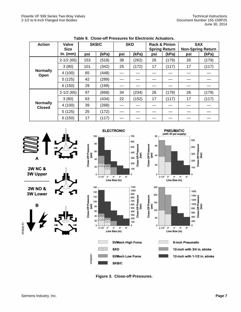
Table 9. Close-off Pressures for Electronic Actuators.
Action Valve Size
In. (mm)
SKB/C SKD Rack & Pinion Spring Return
SAX Non-Spring Return
psi (kPa) psi (kPa) psi (kPa) psi (kPa)
Normally Open
2-1/2 (65) 153 (518) 38 (262) 26 (179) 26 (179) 3 (80) 101 (342) 25 (172) 17 (117) 17 (117) 4 (100) 65 (448) — — — — — — 5 (125) 42 (289) — — — — — — 6 (150) 29 (199) — — — — — —
Normally Closed
2-1/2 (65) 97 (668) 34 (234) 26 (179) 26 (179) 3 (80) 63 (434) 22 (152) 17 (117) 17 (117) 4 (100) 39 (268) — — — — — — 5 (125) 25 (172) — — — — — — 6 (150) 17 (117) — — — — — —
Figure 3. Close-off Pressures.

Technical Instructions Flowrite VF 599 Series Two-Way Valves Document Number 155-159P25 2-1/2 to 6-inch Flanged Iron Body June 30, 2014
Page 8 Siemens Industry, Inc.
Operation Figure 4 shows the normally open valve in the open or full flow position and the normally closed valve in the closed or zero flow position. The actuator spring provides the necessary force to hold the stem in the raised or normal position.
In the event of power failure, a spring return actuator returns the valve to its normal position. Non-spring return actuators will hold the last commanded position. See the Technical Instructions of the various actuators for additional information.
Normally Open Normally Closed Figure 4. Operation.
Sizing The sizing of a valve is important for correct system operation. An undersized valve will not have sufficient capacity at maximum load. An oversized valve may initiate cycling, and the seat and throttling plug may be damaged because of the restricted opening. Correct sizing of the control valve for actual expected conditions is considered essential for good control.
Some variables which must be determined are: • The medium to be controlled: steam, water, etc. • The maximum inlet temperature and pressure of the medium at the valve.
• The pressure differential that will exist across the valve under maximum load demand.
• The maximum capacity the valve must deliver.
• The maximum line pressure differential that the valve actuator must close against.
See AB-1 Control Valve Selection and Sizing (Document Number 140-0038) for further recommendations. See Table 4 through Table 7, and Figure 2 for valve capacities.
Installation • Install the valve so that the flow follows the direction of the arrow indicated on the valve body identification tag.
• For best performance, install the valve assembly with the actuator above the valve body. The valve and actuator can be installed in any position between vertical and horizontal. It is not recommended to install the valve assembly below horizontal or upside down.
• For flange dimensions and bolt hole information, see Cast Iron Flange Dimensions for 2-1/2 through 6” Valves Technical Bulletin (155-303P25 [TB 248]).
• Allow sufficient space for servicing the valve and actuator. See Table 14 for valve body dimensions. See Table 13 and Figure 7 for dimensions of the service envelope recommended around the actuator.
NOTE: Instructions for field mounting an actuator, spring adjustments, wiring diagrams, and start-up are covered in the Technical Instructions and Installation Instructions for each actuator.

Flowrite VF 599 Series Two-Way Valves Technical Instructions 2-1/2 to 6-inch Flanged Iron Bodies Document Number 155-159P25 June 30, 2014
Siemens Industry, Inc. Page 9
Service Kits Table 10. Rebuild/Repack Service Kits Part Numbers.
Valve Description ANSI Class 125 Valve No.
ANSI Class 250 Valve No.
Kit No.
Stai
nles
s St
eel T
rim
NO 2-1/2 (65), = % 599-05960 599-05920 599-10130 NO 3 (85), = % 599-05961 599-05921 599-10131 NO 4 (100), = % 599-05962 599-05922 599-10132 NO 5 (125), = % 599-05963 599-05923 599-10133 NO 6 (150), = % 599-05964 599-05924 599-10134 NC 2-1/2 (65), = % 599-05970 599-05930 599-10140 NC 3 (85), = % 599-05971 599-05931 599-10141 NC 4 (100), = % 599-05972 599-05932 599-10142 NC 5 (125), = % 599-05973 599-05933 599-10143 NC 6 (150), = % 599-05974 599-05934 599-10144
Bro
nze
Trim
NO 2-1/2 (65), = % 599-05980 599-05940 599-10135 NO 3 (85), = % 599-05981 599-05941 599-10136 NO 4 (100), = % 599-05982 599-05942 599-10137 NO 5 (125.), = % 599-05983 599-05943 599-10138 NO 6 (150), = % 599-05984 599-05944 599-10139 NC 2-1/2 (65), = % 599-05990 599-05950 599-10145 NC 3 (85), = % 599-05991 599-05951 599-10146 NC 4 (100), = % 599-05992 599-05952 599-10147 NC 5 (125), = % 599-05993 599-05953 599-10148 NC 6 (150), = % 599-05994 599-05954 599-10149
Line
ar, S
team
Pac
king
NO 2-1/2 (65) 599-06040 599-06120 599-10110 NO 3 (85) 599-06041 599-06121 599-10111 NO 4 (100) 599-06042 599-06122 599-10112 NO 5 (125) 599-06043 599-06123 599-10113 NO 6 (150) 599-06044 599-06124 599-10114 NC 2-1/2 (65) 599-06050 599-06130 599-10115 NC 3 (85) 599-06051 599-06131 599-10116 NC 4 (100) 599-06052 599-06132 599-10117 NC 5 (125) 599-06053 599-06133 599-10118 NC 6 (150) 599-06054 599-06134 599-10119
Line
ar, N
orm
al D
uty
Pack
ing
NO 2-1/2 (65) 599-06060 599-06140 599-10100 NO 3 (85) 599-06061 599-06141 599-10101 NO 4 (100) 599-06062 599-06142 599-10102 NO 5 (125) 599-06063 599-06143 599-10103 NO 6 (150) 599-06064 599-06144 599-10104 NC 2-1/2 (65) 599-06070 599-06150 599-10105 NC 3 (85) 599-06071 599-06151 599-10106 NC 4 (100) 599-06072 599-06152 599-10107 NC 5 (125) 599-06073 599-06153 599-10108 NC 6 (150), Linear 599-06074 599-06154 599-10109

Technical Instructions Flowrite VF 599 Series Two-Way Valves Document Number 155-159P25 2-1/2 to 6-inch Flanged Iron Body June 30, 2014
Page 10 Siemens Industry, Inc.
Construction of the Two-Way Valve
Figure 5. Two-Way Normally Closed.
Figure 6. Two-Way Normally Open.

Flowrite VF 599 Series Two-Way Valves Technical Instructions 2-1/2 to 6-inch Flanged Iron Bodies Document Number 155-159P25 June 30, 2014
Siemens Industry, Inc. Page 11
Parts List
Table 11. Parts List for Two-Way Flanged Valves. Item Part Name Part No. Qty Material
1 Packing Cartridge Assembly – 1 – 2 Gasket – 1 Copper 3 Packing Spring – 1 Stainless Steel 4 Packing Bearing – 1 Bronze 5 Cap Screw 4 - 8 Plated Steel 6 Bonnet – 1 Cast Iron 7 Gasket 1 - 8 Valve Body – 1 Cast Iron 9 Stem and Plug Assembly – 1 Bronze or
Stainless Steel 10 O-ring – 1 EP 11 Cap – 1 Cast Iron 12 Cap Screw – 4 Plated Steel Packing Kit
Normal Duty Service Steam Service
599-08020 599-08021
–
Items 1 and 2
Rebuild/Repack Kit Normally Closed
Table 10 – Items 1, 2, 3, 4, 7, 9, and 10
Rebuild/Repack Kit Normally Open
Table 10 – Items 1, 2, 3, 4, 7, and 9
Flange Gasket and Cap Screw Replacement Kit
Table 12 Items 5 and 7
______________________________________________________________________________________________
Service Kits
Table 12. Flange Gasket and Cap Screw Replacement Kits.
Description Line Size Inch (mm)
Kit Part Number
Cap Screw Size - Inch
ANSI Class 125
2-1/2 (65) 599-09236 5/8 – 11 × 1-1/2 3 (80) 599-09237 5/8 – 11 × 1-3/4 4 (100) 599-09238 5/8 – 11 × 2 5 (125) 599-09239 3/4 – 10 × 2 6 (150) 599-09240 3/4 – 10 × 2
ANSI Class 250
2-1/2 (65) 599-09241 3/4 – 10 × 2 3 (80) 599-09242 3/4 – 10 × 2-1/2 4 (100) 599-09243 3/4 – 10 × 2-1/2 5 (125) 599-09244 3/4 – 10 × 2-3/4 6 (150) 599-09245 3/4 – 10 × 3

Technical Instructions Flowrite VF 599 Series Two-Way Valves Document Number 155-159P25 2-1/2 to 6-inch Flanged Iron Body June 30, 2014
Page 12 Siemens Industry, Inc.
Dimensions
NOTE: See Table 13 for actuator and recommended service envelope dimensions and Table 14 for actual valve dimensions.
Figure 7. Dimensions.
Table 13. Dimensions of the Actuator and Recommended Service Envelope. Dimensions in Inches (Millimeters).
Actuator
Actuator Prefix Code
Actual Height of Actuator
H1
Service Height
H
Actual Width or Diameter of
Actuator W1
Service Width
W
8" Pneumatic 277 278 283 284
14-1/8 (359)
26 (660) 8-3/4 (222) diameter 21 (533)
12" Pneumatic 279 281 285 287
17-7/8 (454)
30 (762) 15-1/8 (384) diameter
27 (686)
SKB/C with handle closed
289 290 291 292 293 294
14-3/4 (375)
22-3/4 (578)
7 (178) width × 8-15/16 (226) depth
25 (635)
SKD 267 274 275 276
11-13/16 (300)
19-3/4 (500)
5 (127) width × 6-5/8 (169) depth
14-1/2 (360)

Flowrite VF 599 Series Two-Way Valves Technical Instructions 2-1/2 to 6-inch Flanged Iron Bodies Document Number 155-159P25 June 30, 2014
Information in this publication is based on current specifications. The company reserves the right to make changes in specifications and models as design improvements are introduced. Flowrite is a registered trademark of Siemens Industry, Inc. Teflon is a registered trademark of DuPont. Other product or company names mentioned herein may be the trademarks of their respective owners. © 2014 Siemens Industry, Inc.
Siemens Industry, Inc. Building Technologies Division 1000 Deerfield Parkway Buffalo Grove, IL 60089 USA + 1 847-215-1000
Your feedback is important to us. If you have comments about this document, please send them to [email protected]
Document No. 155-159P25 Printed in the USA
Page 13
Table 14. Valve Dimensions and Weight.
Valve Action
Nominal Valve Size
inches
ANSI Class 125 ANSI Class 250
Dimensions in Inches (mm)
Weight lbs. (kg)
Dimensions in Inches (mm)
Weight lbs. (kg)
(mm) A B C A B C
Normally Open
2-1/2 10-7/8 11 4-7/8 60 11-1/2 11 4-7/8 76 (65) (276) (281) (123) (27) (292) (281) (123) (34)
3 11-3/4 12-1/4 5-5/16 76 12-1/2 12-1/4 5-5/16 99 (80) (299) (312) (135) (34) (318) (312) (135) (45)
4 13-7/8 13-9/16 6-5/16 124 14-1/2 13-5/8 6-5/16 160 (100) (352) (345) (160) (56) (368) (344.7) (160) (73)
5 15-3/4 15-3/16 7 155 16-5/8 15-3/16 7 208 (125) (400) (385) (177) (70) (422) (385) (177) (94)
6 17-3/4 16-3/4 7-7/8 212 18-5/8 16-3/4 7-7/8 302 (150) (451) (426) (200) (96) (473) (426) (200) (137)
Normally Closed
2-1/2 10-7/8 10-5/8 4-7/8 58 11-1/2 11 5-3/8 74 (65) (276) (269) (125) (26) (292) (279) (135) (34)
3 11-3/4 11-15/16 5-5/8 75 12-1/2 12-7/16 6 98 (80) (299) (303) (142) (34) (318) (315) (154) (44)
4 13-7/8 13-15/16 6-5/8 123 14-1/2 14-3/8 7 159 (100) (352) (354) (168) (56) (368) (364) (178) (72)
5 15-3/4 15-1/4 7-1/2 153 16-5/8 15-3/4 7-3/4 207 (125) (400) (388) (185) (69) (422) (399) (196) (94)
6 17-3/4 17-1/16 8-3/16 209 18-5/8 17-1/2 8-5/8 299 (150) (451) (433) (207) (95) (473) (444) (218) (136)


![1348 1548 1948 PUB 05-04 COVERS€¦ · 6 00764506 1 collar-inner-guard-retainer 7 00754330 6 bolt, nylon - safety shield] 8 00764507 1 collar-outer-guard-retainer 9 00774079 1 kit,slide](https://img.dokumen.tips/doc/110x75/5fcd32fe6ec474559a50ef62/1348-1548-1948-pub-05-04-covers-6-00764506-1-collar-inner-guard-retainer-7-00754330.jpg)