Embed Size (px)
Citation preview

"TRADER" SERVICE DAT A No. 91June 19, 1~40
ServicingHudson
THE MOTOR TRADER
the
Sixes and Eight, 1939A·HIGH degree of standardisation
has been achieved in the designof the Hudson range, many
components being common to alltypes.Briefly the lIZ, the smallest model,
has a 16.9 h.p. engine. Next in sizeis the Six, with a z1.6 h.p. engine.The Country Club series embraces thelong-wheelbase Six and the. Eight ofthe same wheelbase. There is also along-wheelbase Eight.
Although the Electric Hand gearchange was used chiefly on 1938models, being fitted to only a few 1939cars, a description of it is included,as its apparent complexity may detersome repairers from attempting to dealwith simple faults.Flat rate schedules for repairs are
still being operated by Hudson Motors,and a selection of prices is given hereunder the appropriate headings. Theyhave, however, owing to wartime con-ditions, been raised, and 10 per cent.should be added to prices given.Apart from S.A.E. spanners, special
tools are not required. A universaltype of hub puller is necessary for axlellel'V'ice.
• < ENGINE DATA
112 Sill Eight~No. or c,lind, ... 6 6 SBor. "Itroke :
mm • ...... 67.45x127 78.2 x 127 76.2 x 114III. 2Hx5 3x5 3x4!Capr.Jti;·······Coc•......... 2,723 3,475. 4,162cu. In. 167 212 254
R.A.O.rated h.p. 16.9 21.6 2S.SB.H.P •......... 76 101 122
at r.p.m .... 3,SOO 4,000 4,200
Oo;:,~.i~~ .... 6.25 6.25Flrln, order ... 153624 11258374.Valve clearance<IIot) :1 inlet .006' .006'• lIIIau.i .. ·.. .OOS' .008"
Breaker , ... ::: .020' .017"
PIlIp: type ... Ohamplon d8, 14 mm •.IIP ... •032",
tlpacltl., :10 plI. I• ump ......... 14 pll •
wmr.ptem 2t gall. 3ilal,.
...~~.
Instruments andControls, Hudson
Six:1. Petrol lau,a.2. 011 pranur. indi-
cator.3. Ash tra,.4. Beraen wiper control.5. D,namo cha"a in.
dicator.6. Water temperatura
gaup.7. 8peedometer.S. Horn button.9. Ooka.10. Raadlamp beam in-
dicator.11. Bonnet lock handla.12. Slnicalight.
13. Gear lIver.14. Lightswitch.16. Ignition lock.18. Starter switch.17. Scuttle vantilator
control.18. Electric clock.
ENGINE
MOUNTING AND REMOVALThree rubber mountings, one each
side of front bearer plate, one belowfront of gear box. Pull bolts up tightagainst distance pieces and pin.Engine and gear box come out as
unit. Remove bonnet top (undo hingeat front end), bonnet sides, radiatorand lid of gear box, disconnect con-trols, pipes, wires and propeller-shaftfront end. Fit slings below frontof sump and round gear box. Drawout forwards and upwards .
Remoue engine and gear box fromframe, refit or fit exchange engine, Six£z ISS.; Eight £3 5s.
Renew rubber mountings: front 8s.;rear £z lOS. ,Overhaul engine (including re-
moval, dismantling, refitting all bear-ings and camshaft, grinding valves, re-assembling and replacing), Six£Is lOS.; Eigh.t £17.
CRANKSHAFTThree main bearings on Sixes, five
on Eights. White metal-lined bronzeshells located in housings by counter-sunk screws. Running clearanceo.oozin.. end float, controlled bycentre bearing flanged at both sides,o.oodin.vo.orain. Shims between capsand crankcase for adjustment of run-ning clearance. Scrape to fit if neces-
l'
Articles in this series are wriUen bythe Techniool staff of "The MotorTrader" and checked by the servicemanagers of the vehicle manufacturers.They appear fortnighD.y. No. 92- •
CASE, TR.ACTOR.. July a.
sary. Bearings can be taken up withengine in place, but to change or in-spect top halves engine must be takenout and crankshaft removed.
CRANKSHAFT DATA.
Main Bearings---------- Crank-Front No.2 Centre No.4 Rear pins
-- -- -- -- --Length:
~r 11"Sixes ... W - If' -Eight ... lin W It" tiN I"
Diameter:Sixes ... 2H' - 21' - 213" 1*"••Eight ... 23
92• 2-11-' 2»" 2ln 21 :1" 1*"3.
Flywheel bolted to crankshaftflange. Shrunk on starter ring gear,134/9 teeth.Front and rear main bearing caps
fit machined openings in crankcase,finishing flush with sump flange.Grooves in case and caps for packing.Front cap has horizontal as well lasvertical grooves, and must be removedwith puller to shear packing. Whenreplacing use cotton wick driven ittwith long punch. See that split oilretainer on rear bearing fits tightly.Torsional vibration damper keyed to
front end of. crankshaft in front oftiming gear with distance piece be-tween which passes through oil sealin timing case. Assembly secured bystarter dog nut with male threadscrewed into hollow ~nd of shaft.Damper is in two halves bolted to-
gether by setscrews, can be dis-mantled for replacing rubbers .Adjust main bearings (sump re-
. moved), Six £z 5s.; Eight £z 175. 6d.
CONNECTING RODSBig ends direct white-metalled.
Running clearance o.oozin.. side clear-
ii THE MOTOR TRADER'
HUDSON
June 19, 1940
MAINTENANCE DIAGRAM
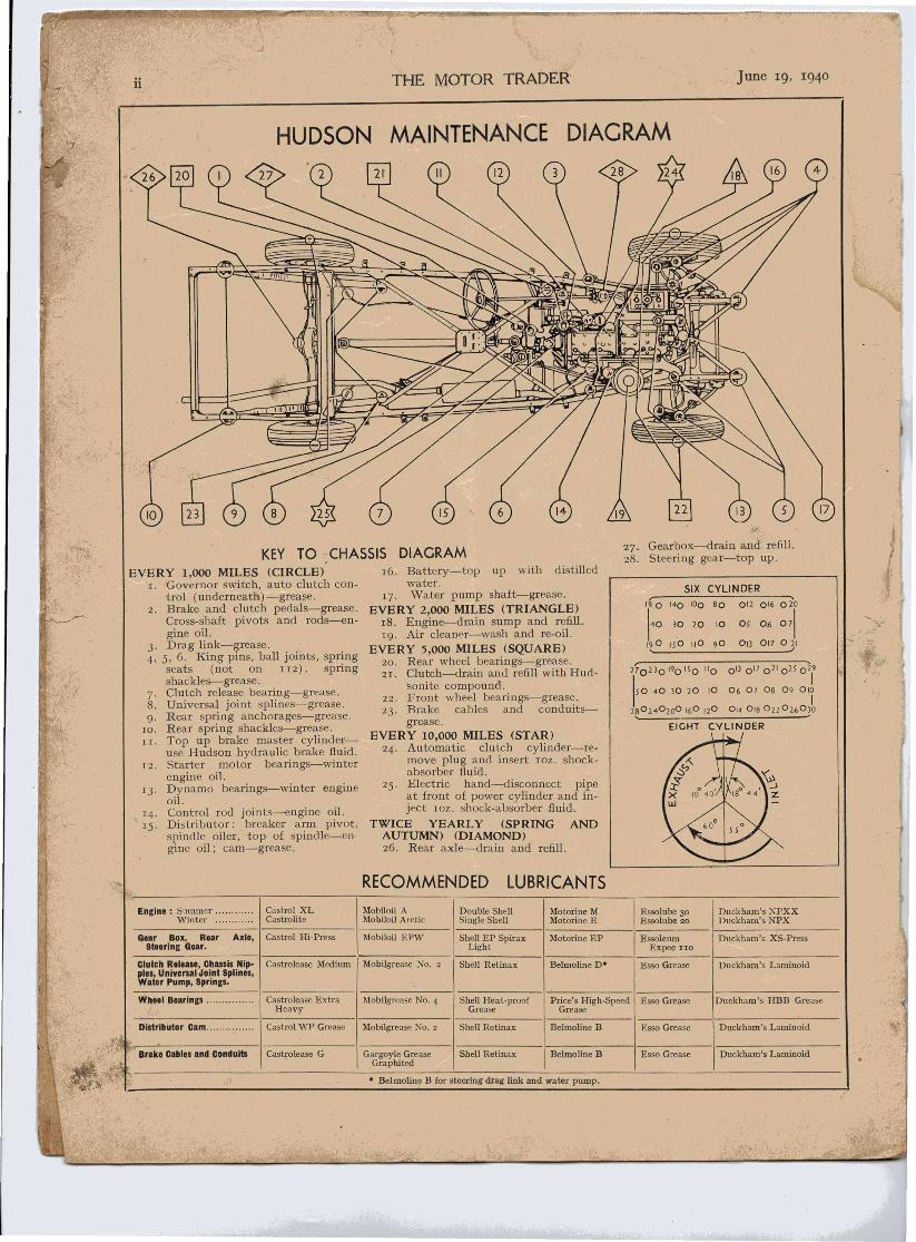
KEY TO CHASSIS DIAGRAMEVERY 1,000 MILES (CIRCLE)
I. Governor switch, auto clutch con-trol (undemeathj-s-grease.
2. Brake and clutch pedals-grease.Cross-shaft pivots and rods-en-gine oil.
3. Drag link-grease.4, 5, 6. King pins, ball joints, spring
seats (not on 112) , springshackles-grease.
7. Clutch release bearing-grease.S. Universal joint splines-grease.g. Rear spring anchorages-grease.ro. Rear spring shackles-grease.II. Top up brake master cylinder-
use Hudson hydraulic brake fluid.12. Starter motor bearings-winter
engine oil.13. Dynamo bearings-winter engine
oil.,14. Control rod joints-engine' oil.15. Distributor: breaker arm pivot,
spindle oiler, top of spindle-s-en-gine oil; cam-grease.
16. Battery-top up with distilledwater.
17. Water pump shaft-grease.EVERY 2,000 MILES (TRIANGLE)IS. Engine-drain sump and refill.Ig. Air cleaner-wash and re-oil.
EVERY 5,000 MILES (SQUARE)20. Rear wheel bearings-grease.21. Clutch-drain and refill with Hud-
sonite compound.22. Front wheel bearings-grease.23. Brake cables and conduits-
grease.EVERY 10,000 MILES (STAR)24. Automatic clutch cylinder-re-
move plug and insert IOZ. shock-absorber fluid.
25. Electric hand--disconnect pipeat front of power cylinder and in-ject IOZ. shock-absorber fluid.
TWICE YEARLY (SPRING ANDAUTUMN) (DIAMOND)26. Rear axle-drain and refill.
RECOMMENDED LUBRICANTS
27. Gearbox-drain and refill.2S. Steering gear-top up.
SIX CYLINDER
f4:140 100 BO 012 016 020
30 20 10 Os 06 071
190 ISO 110 90 01) 017 021
270230'90'50 "0 0') 017021025029
150 40 )0 20 10 06 07 Os 09 Olt
28024°20° 160 120 0'4 0,8022 0260)0
---------Engina : Summer ....... Castrol XL Mobiloil A Double Shell Motorine M Essolube 30 Duckham's NPXX
Winter ......... ... Castrolite Mobiloil Arctic Single Shell Motorine E Essolube 20 Duckham's NPX
Gear Box, Rear Axle, Castrol Hi-Press Mobiloil EPW Shell EP Spirax Motorine EP Essoleum Duckham's XS-PressSteering Gear. Light Expee 110
Clutch Release, Chassis Nip- Castrolease Medium Mobilgrease No. 2 Shell Retinax BelmolineD· Esso Grease Duckbam's Laminoidplas, Universal Joint Splines,Watar Pump, Springs.
--------Wheal Bearings. Castrolease Extra Mobilgrease NO.4 Shell Heat-proof Price's High-Speed Esso Grease Duckham '5 HBB Grease
Heavy Grease Grease
Distributor Cam Castrol WP Grease Mobilgrease No.2 Shell Retinax Belmoline B Esso Grease Duckham's Laminoid
Castrolease G Gargoyle Grease Shell Retinax BelmolineB Esso Grease Duckham's LaminoidGraphited
• Belmoline B for steering drag link and water pump.
June 19, 1940 THE MOTOR TRADER
"TRADER" SERVICE DAT A (Continued)HUDSON SIXES AND EIGHT
ance o.oooin.eo.or oin. No shims arenow provided. If worn fit replace-ment rods.If bearing runs, carefully clean all
traces of white-metal from oil troughsand webs.Big end caps are now secured with
Palnut spring steel locknuts.Fit rods so that oil scoops on big
end caps face to off side. .Small ends bronze bushed. Gud-
geon pins should be hand push fit atshop temperature.
PISTONSLo-Ex, T slot. Larger Six and
Eight have cam-ground skirt. Skirtclearance on smaller Six 0.002in., oncam-ground pistons .0.00Iin.-o.002in.on thrust side.
Replacement pistons available inoversizes covering worn bores andstandard rebores up to 0.020in. Canbe ordered by code letter (stamped onhead) as follows:-
CYLINDER PISTON RINGOVenize Code Code OV.nizeStandard A B . }0.0005 B C0.001 C D atandard0.0015 D E0.002 E F0.0025 G0.003 H 0.0030.0035 I 0.0030.004 ~ 0.0030.0045 K 0.0030.005 L 0.0050.010 AO BO 0.0100.0105 BO CO 0.0100.011 CO DO 0.0100.0115 DO EO 0.0100.012 EO FO 0.0100.0125 GO 0.0100.013 HO 0.0100.0135 10 0.0100.014 ~O 0.0100.0145 KO 0.0100.015 LO 0.0150.020 BB 0.0200.021 DD 0.0250.022 FF 0.025
Cylinder bore code is stamped ontappet cover face of cylinder block.Pistons are stamped on head with codeletter and weight. For instance 10
3Pistons should all bemeans 10.30z.
same weight.Four rings, all above pin on smaller
Six, three above, one below pin onlarger Six and Eight. Lower two oilcontrol rings. All rings are pinned toprevent turning. Gap o.oogin.-o.o r rin., free fit in grooves withoutplay.
Gudgeon pin, located by circlips.should be push fit in piston at boiling.temperature.
Big ends will pass through bores onall but smaller Six, on which assemblyshould be pushed up until gudgeonpin can be driven out, con-rod thenbeing withdrawn from' below, andpiston through top. ';"Fit new gudgeon pins r piston
f\\
\
rings [including removing cylinderhead), £3 145.Fit new gudgeon pin (2I.6 h.p.),
16s.; (16.g h.p.), £2.Remove, clean and replace cylinder
head, Six £I 55.; Eight £I 105.
CAMSHAFTDriven by helical gears, large wheel
bakelite. Three bearings on Sixes, fiveon Eight, white-metal bushes,dowelled from outside by short copperpipes punched in. Running clearance0.002in. End thrust taken on frontface of crankcase and by spring-loaded plunger in end of camshaftpressing against button on timingcover. Timing wheels centre-punchmarked for correct mesh. Large wheelbolted .to flange on camshaft withthree unequally spaced bolts. Headswired together.Camshaft can be removed with
engine in place if tappets, oil pump,petrol pump and radiator are removed.Remove and refit camshaft (includ-
ing adjusting tappets and resettingvalve and ignition timing), Six £4 55.;Eight £4 105.Renew .all camshaft bearings (com-
plete operation), Six £7; Eight £8 lOS.
Remove and refit timing cover, allengines, £1 155.
VALVESSide by .side. Same size OR Sixes
but different. material, so not inter-changeable.
iii
VALVE DATA
Sixes EiCht
Both Inlet Exhaust--- ---
Head diameter .. 13" IV' li""Stem diameter ... r" t" rFace angie 450 45' 45'Spriug pressure@2" ... 401bs. 401bs. 401bs.
Single springs in sheaths.Valve guides renewable. Press in
from above until top is Inin. belowtop face of block on Sixes, ta-in. onEights. Ream out to o.oozin. largerthan valve stem when in place. .
TAPPETSShoe type, shoes sliding in slotted
guides. Each guide is detachableseparately, pairs being clamped inplace by flat plate registering with flaton guide flanges.
lUBRICA TIONOscillating double-acting plunger
pump bolted ,to side of crankcase,driven by skew gears from 'camshaffat"·! / r ath engine speed. No valves.Oil is fed at low pressure to timing case.and check valve at rear of crankcase(connected to electric tell-tale switch)whence it passes to troughs in top ofsuni!>. Con-rod dippers feed oil tobig ends and splash up to cylinderwalls. Splash collected in troughs highup on crankcase walls and led bygravity to main bearings. Overflowreturns to bottom of sump via filterscreens.
Pressed-steel sump. Bottom sectionof suction pipe and return pipe fromrear bearing oil retainer soldered in,
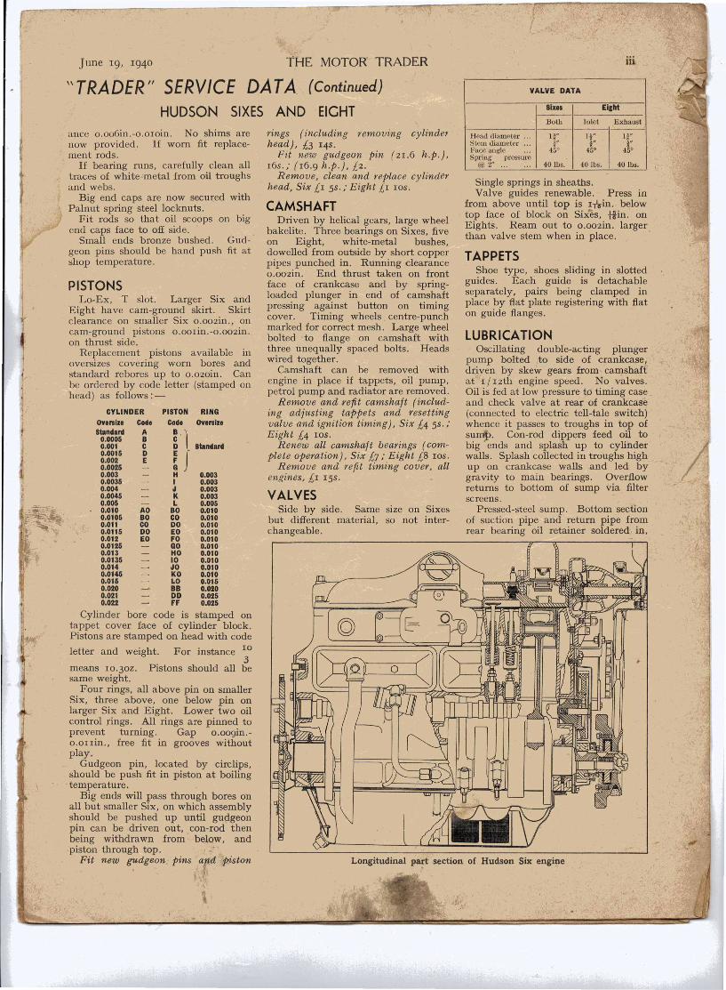
Longitudinal pa~t section of Hudson Six engine
iv THE MOTOR TRADER
"TRADER" SERVICE DATA (Continued)HUDSON SIXES AND EIGHT
standing proud of top flange and re-'gistering with holes in case and rearbearing cap. If sump is removed forcleaning, always refill troughs beforerefitting.
Remove and refit oil pump, 8s.Overhaul oiling system (including
removing sump, cleaning out and re-placing suction pipe if necessary), Six12S.; Eight ISS.
FUEL FEEDAC pump with built-in vacuum
booster for suction windscreen wiperon all models except smaller Six.Eccentric-operated from camshaft.Vacuum booster works on same prin-ciple as fuel pump, with diaphragmassembly bolted to underside of pump.Leads to intake manifold and wiper.
'\- If engine smokes badly and con-sumes oil rapidly for no apparent rea-son, suspect punctured diaphragm ofvacuum booster. As one side is opento crankcase and other is sublect todepression from inlet manifold, oil willbe sucked into cylinders throughpuncture. Locate fault by disconnect-ing' lead to manifold while engine isrunning. No oil should be present inpipe.
Remove and replace fuel pump, 8s.Overhaul fu6l pump, lIS.
CARBURETTORCarter downdraught. Single with
manual choke on smaller Six, dualwith automatic choke on larger Sixand Eight.Metering rod is only setting which
can normally be altered.
METERING ROD SIZE8 (part NOI.)
21.6 Six16.9 Six and Eight
Standard ... ... 7&-281 7&-348One size weak ... 7&-282 71)-·3572 sizes weak ... 7&-283 7&-368
Normal setting of slow-runningadjusting screw is i-I turn open onsingle and i-I tum on dual carburet-tor.
Float level should be lin. on singleand -l,in. on dual carburettor, mea-sured from top of float to bottom faceof float chamber lid.AC oil-wet air cleaner. Clean in
.petrol and re-oil filter unit every 2,000
miles.
IGNITIONAutolite coil. Distributor located
on off side by clamp plate bolted toblock. Centrifugal advance.
Set points to break at T.D.C.
COOLING SYSTEMPump, fan and non - adjustable
thermostat, which is set to start open-ing at ISO deg.-r55 deg. F., andshould be fully open at 185 deg. F.Spring-loaded self-adjusting sealing
gland.To remove pump from engine drain
radiator, slacken fan belt and discon-nect hoses. Take out two setscrewsto cylinder block. Do not splitpump in place.To dismantle remove rear half of
housing, cut burr off spindle at im-peller end and drive spindle out ofimpeller. Pulley flange and spindleare supplied as unit and should notbe separated. Front and rear bushesare pressed in and flanged at outerends.When reassembling seal in impeller
place conical spring with large end to-wards impeller, followed by washer,shaft seal andseal thrustwasher whichfits in slots,securing assem-bly with springring. Insertpulley flange andspindle intopump body withthrust washer,ass e m b 1e im-
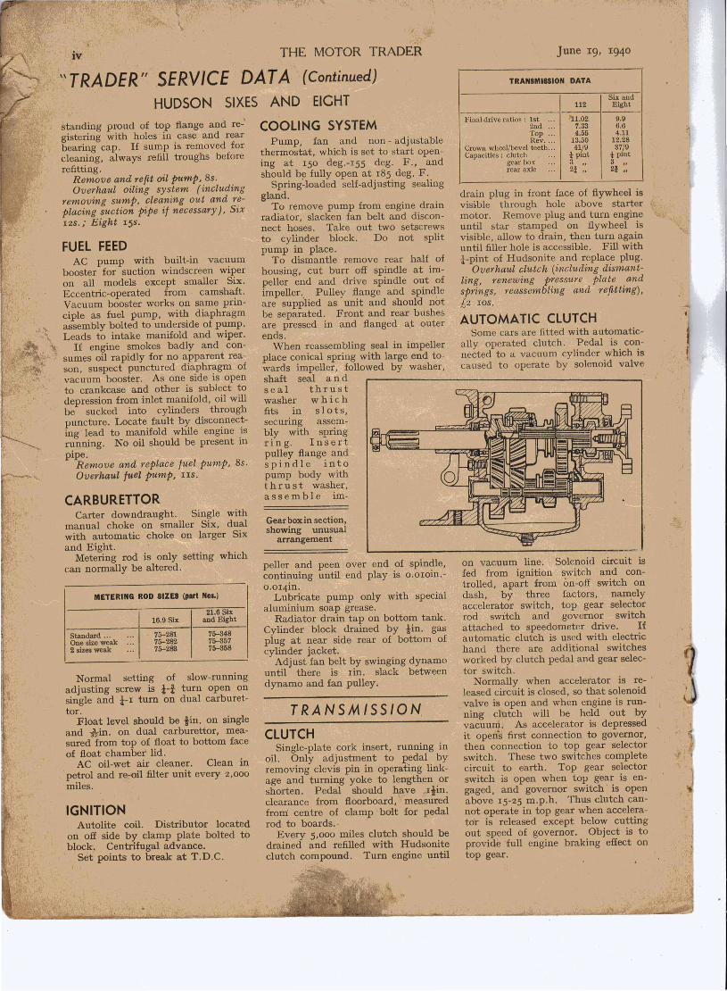
Gear boxin section,showing unusual
arrangement
June 19, 1940
TRANSMISSION DATA
Six and112 Eight
Final drive ratios: 1st ... 1').1.02 9.92nd 7.33 6.6Top ::: 4.55 4.11Rev .... 13.50 12.28
Crown wheel/bevel teeth ... 41/9 37/9Capacities: clutch i pint t pint
gearbox 3 3rear axle ... 21 ::. 21 ::
drain plug in front face of flywheel isvisible through hole above startermotor. Remove plug and turn engineuntil star stamped on flywheel isvisible, allow to drain, then turn againuntil filler hole is accessible. .Fill withi-pint of Hudsonite and replace plug.
Overhaul clutch (including dismant-ling, renewing pressure plate andsprings, reassembling and refitting),£2 ros.
AUTOMATIC CLUTCHSome cars are fitted with automatic-
ally operated clutch. Pedal is con-nected to a vacuum cylinder which iscaused to operate by solenoid valve
peller and peen over end of spindle,continuing until end play is o.oroin.-0.014in.Lubricate pump only with special
aluminium soap grease.Radiator drain tap on bottom tank.
Cylinder block drained by tin. gasplug at near side rear of bottom ofcylinder jacket .Adjust fan belt by swinging dynamo
until there is rin. slack betweendynamo and fan pulley.
TRANSMISSION,
CLUTCHSingle-plate cork insert, running in
oil. Only adjustment to pedal byremoving clevis pin in operating link-age and turning yoke to lengthen orshorten. Pedal should have liin.clearance from floorboard, measuredfroni centre of clamp bolt for pedalrod to boards.·
Every 5,000 miles clutch should bedrained and refilled with Hudsoniteclutch compound. Turn engine until
on vacuum line. Solenoid circuit isfed from ignition switch and con-trolled, apart from on-off switch ondash, by three factors, namelyaccelerator switch, top gear selectorrod switch and governor switchattached to speedometer drive. Ifautomatic clutch is used with electrichand there are additional switchesworked by clutch pedal and gear selec-tor switch.Normally when accelerator is re-
leased circuit is closed, so that solenoidvalve is open and when engine is run-ning clutch will be held out byvacuum. As accelerator is depressedit open's first connection to governor, -,then connection to top gear selectorswitch. These two switches completecircuit to earth. Top gear selectorswitch is open when top gear is en-gaged, and governor switch' is openabove 15-25 m.p.h. Thus clutch can-not operate in top gear when accelera-tor is released except below cuttingout speed of governor. Object is toprovide full engine braking effect ontop gear.

June 19, 1940
HUDSON"TRADER" SERVICE DATA
SIXES
THE MOTOR TRADER
(Continued)AND EIGHT
GEAR BOXOf unusual design but quite straight-
forward. Three-speed, helical con-stant mesh and second gears. Re-
.,. verse pinion slides out of engagementwhen forward gears are used. Secondgear driven pinion turns on extensionof primary shaft gear, each having in-ternal teeth. Splined sleeve, withteeth formed on front end, slides onmainshaft, moved by selector fork,picking up on top or second gearinternal teeth.Box can be removed from car with
engine in place if rear of engine isjacked up. Disconnect gear changeoperating levers and cables. Removebox complete with bell-housing.To dismantle box remove cover and
lever, take off clutch interlocking rodsfrom each side of box by undoing nutsat bottom and sliding downwards (oneor both of these rods are sometimesomitted). Remove bell-housing, pulloff universal joint flange and speedo-meter drive housing and gear. Removeselector locking plungers from eachside of box and take nut selector rodsand forks. Remove front main bear-ing cover. Drive back bottom gearmainshaft pinion 'far enough to. un-cover split locking ring, take off ringand pull out, mainshaft with bearingbackwards, lifting out top- and second-gear sleeve and bottom gear pinionfrom inside. Primary shaft can nowbe lifted out through top of box, withtop and second constant mesh pinions.
Mainshaft spigot bearing has 26needle rollers and seven thrust balls.Do not lose these when dismantling.Next remove reverse shaft cover,
which comes away with stationaryshaft. Fixed gear and splined sleevewith sliding gear can now be liftedout.To remove layshaft, take off rear
plain bearing housing, with thrust-washer and spacer. Prise top andsecond layshaft gears apart with blunttool until top gear pinion is off splines,turn shaft slightly so that splines, donot register, and drive- second gearpinion forward. Then place selectorin neutral and, holding three gears to-gether, pull out shaft backwards.Bottom and reverse selector mechan-ism can then be reached.Assembly is a reversal of these
operations.To remove second gear from pri-
mary shaft, knock out expandingspring ring in back of second gearpinion with punch through holes inside of gear. Split white-metal facedthrust-washer can then be "juggled"out and gear will slide off, with oppo-site thrust washer at inside end.
••Handy-shift" remote control onsteering column is direct mechanicalcontrol, selector rods being moved byrod and levers. Cross-change iseffected by cable operated by up-and-down movement of gear lever shaft.
Overhaul gear box, £3 lOS.Remove and refit gear box, £2 4S.
ELECTRIC HANDThis operates on principles com-
paratively simple in practice, althoughlayout appears complicated at firstsight.
Standard gear box is used, withprovision for manual control. Fore-and-aft movement of each selector rodis effected by a large vacuum cylinder,closed at each end, and a double-acting piston with coupling rod con-nected to lever and transverse controlshaft.
Cross-change movement from onerod to other is effected by a single-acting vacuum unit with rubberdiaphragm and spring return, itsaction sliding control shaft across bymeans of a bell crank. Admission ofvacuum to cylinder and diaphragmunit is via pipes. connected to a valvechest containing three double-actionvalves operated by celluloid plungers.Steering-column gear s e 1e c tor
operates in "H" slot and controlsvalve solenoids through sliding andsemi-rotary switch movement. Asliding contact assembly on gear box,
To AtmOl!lphere t(Carburettol' a i r--ct eener )
v
actuated by selecto~ control, and aninterlocking switch linked to cross-change unit, complete circuits.
Operation is as follows: Currentsupply to whole unit is controlled viaignition switch, master switch incor-porated in column control, and clutchpedal-operated circuit-breaker. Selec-tion of gear, or change, is made withclutch engaged, action being sus-pended until pedal is fully depressed,closing circuit-breaker.With hand lever in first gear posi-
tion and breaker closed, current flowsvia master switch to upper rightbrush 5 (see diagram), across sleeve 6to lower brush 18 and wiring tosolenoid terminal 11. Solenoid isenergised, plunger drawn downagainst spring, when valve 13 opensupper port and closes lower port.Vacuum is applied to cross-changeunit, diaphragm of which is drawn inagainst spring.Movement is followed by coupling
link, bell crahk shifting control shaftso that dog engages first and reverseselector rod. Simultaneously, delay-action coupling to interlocking switchcauses it to operate when cross-changetraverse is completed, when sector 9moves to bridge contacts 8 and 10,
while sector 16 moves to bridge 17and 15. .Current now flows from top-left
brush 7 of column control, throughwiring to terminal 10 of interlockswitch via 9 to 8, wiring to centreplate 19 of column control changeswitch, rotor to 20, wiring to plate 21
of gear box contact assembly, acrossthree-brush sliding contactor 22 toplate 23 and wiring to terminal 24 of
Gearboxoontact~~=jlU'r
In;:~~~klng_"""""'"
(Drawn in lat ..and. Rev:)gear position.
Diagram of Electric Hand layout and circuit. See text for numbers
vi THE MOTOR TRADER
\\TRADER" SERVICE DAT A (Continued)HUDSON SIXES AND EIGHT
solenoid group. Solenoid operates,valve 25 opens upper port and closeslower, admitting vacuum to front ofshift cylinder when piston is drawnforward and connecting linkage movescontrol shaft arid selector rod toengage first gear.Two three-brush contactors 22 and
26 are insulated and mounted on asliding member controlled by eitherselector rod movement, so completionof movement into first gear causes con-tactor 22 to move off plates 21 and 23,while contactor 26 moves in to con-nect plates 27 and 28 with neutralisingcentre plate 29, which serves an im-portant purpose. Thus, contactor 22opens solenoid circuit by sliding offplates 21 and 23, usual spring lock re-taining gear in mesh. When changingto second gear first act is movementof hand lever to neutral, when currentfrom 19 of change switch flows tostud 30, wiring to centre plate 29 andthrough contactor 26 to plate 28 andwiring to terminal 3I of centresolenoid, which operates valve 32 andadmits vacuum to back of cylinder,moving selector rod back to neutralposition.
Contactors resume positions asdrawn, opening circuit to solenoid oncompletion of change. When handlever is moved across gate, sleeve 6leaves brushes 7 and 18 insulated andbridges 5 and 33. Brush 18, beingdead, interrupts current to solenoid 12and spring in cross-change unit 14moves control shaft to engage dogs ofsecond-third selector rod. Interlock-ing switch, following cross-changemovements, now assumes a positionwhere contacts 15-16-8 and, 10-9-17are grouped respectively.
Current now follows path: 5-6-33,wire to I5-I6-8, wire to 19 and stud 34of change switch when hand lever isplaced in second gear position. Fromthis point path is: Wire to 27-26-28
"
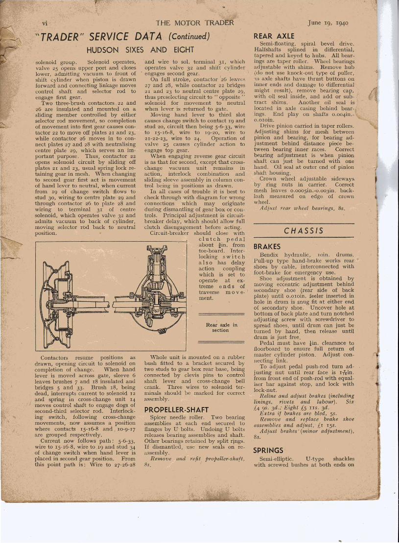
REAR AXLESemi-floating, spiral bevel drive.
Halfshafts splined in differential,tapered and keyed to hubs. All bear-
and wire to sol. terminal 31, which ings are taper roller. Wheel bearingsoperates valve 32 and shift cylinder adjustable with shims. Remove hubengages second gear. I ' (do not use knock-out type of puller,
On full stroke, contactor 26 leaves 'is axle shafts have thrust buttons on27 and 28, while contactor 22 bridges inner ends and damage to differential21 and 23 to neutral centre plate 29, might result), remove bearing cap,thus preselecting circuit to " opposite" with oil seal inside, and add or sub-solenoid for movement to neutral tract shirns.. Another oil seal is,when lever is returned to gate. located in axle casing behind bear-Moving hand lever to third slot ings. End play on shafts 0.004in.-
causes change switch to contact I9 and O.OIOin.stud 20, circuit then being 5-6-33, wire Drive pinion carried in taper rollers.to 15-16-8, wire to 19-20, wire to Adjusting shims for mesh between2I-22-23, wire to 24. Operation of pinion and bearing, for bearing ad-valve 25 causes cylinder action to justment behind distance piece be-engage top gear. tween bearing inner races. CorrectWhen engaging reverse gear circuit bearing adjustment is when pinion
is as that for second, except that cross- shaft can just be turned with onechange vacuum unit remains in hand. Oil seal at outer end of pinionaction, interlock combination and shaft housing.sliding sleeve assembly in column con- Crown wheel adjustable sidewaystrol being in positions as drawn. by ring nuts in carrier. Correct
In all cases of trouble it is best to mesh leaves 0.0005in.-o.o03in. back-check through with diagram for wrong lash measured on edge of crownconnections which may originate wheel.during dismantling of gear box or C011- Adjust rear wheel bearings, 8s.trols. Principal adjustment is circuit-breaker delay, which should allow fullclutch disengagement before acting.Circuit-breaker should close with
clutch pedalabout -lin. fromtoe-board. Inter-locking s wit c halso has delayaction couplingwhich is set tooperate at ex-treme ends oftraverse m 0 v e-ment.
,Rear axle in
section
Whole unit is mounted on a rubberbush fitted to a bracket secured bytwo studs to gear box rear base, beingconnected by clevis pins' to controlshaft lever and cross-change bellcrank. Three wires to solenoid ter-minals should be marked for correctassembly.
PROPELLER-SHAFTSpicer needle roller. Two bearing
assemblies at each end secured toflanges by U bolts. Undoing U boltsreleases bearing assemblies and shaft.Other bearings retained by split rings.If dismantled, use new seals on re-assembly.
Remove and refit propeller-shaft.8s, I
June 19, 1940
CHASSIS
BRAKESBendix hydraulic, roin. drums.
Pull-up type hand-brake works rearshoes by cable, interconnected withfoot-brake for emergency use.
Shoe adjustment is obtained bymoving eccentric adjustment behindsecondary shoe (rear side of backplate) until o.o roin. feeler inserted inhole in drum is snug fit at either endof secondary shoe. Uncover hole atbottom of back plate and turn notchedadjusting screw with screwdriver tospread shoes, until drum can just beturned by hand, then release untildrum is just free.Pedal must have tin. clearance to
floorboard to ensure full return ofmaster cylinder piston. Adjust con-necting link.
To adjust pedal push-rod turn ad-justing nut until rear face is In-in.from front end of push-rod with equal-iser bar against stop, and lock withlock-nut.
Reline and adjust brakes (includinglinings. rivets and labour). Six£4 9S. 3d.; Eight £5 lIS. 3d.
Extra if brakes are bled, 5s.Remove and replace brake shoe
assemblies and adjust. £r I5s.Adjust brakes' (minor adjustment),
8s.
SPRINGSSemi-elliptic. U-type shackles
with screwed bushes at both ends on
I.~.
...

June 19, 1940 THE MOTOR TRADER
\\TRADER" SERVICE DAT A (Continued)HUDSON SIXES AND EIGHT
CHASSIS DATA
Country Club112 Six Six and Eight Eight I.w.b.
Wheelbase ... ... 9' 4- 9' 10- 10' 2" 10' 9"Track; front ... ... 4' 8" 4' 8" 4' 8" 4' 8"
rear ... ... 4' 111' 4' 11tH 4' 11tH 4' Ht"Turning circle ... ... 40' 0" 42' 6" 42' 6" 45' 0"Tyres ... ... ... ... 6.00-16 6.00-16 6.25-16 6.50-16Tyre pressures; front ... 241bs. 241bs. 241bs. 241bs .
I' rear ... 321bs. 321bs. 321bs . 321bs.Petrol tank capacity ... 91 gals. l3t gals. l3i gals. l3i gals.
front axle. Front springs havedivided second leaf, outer endswrapped round eye of main leaf.Inner ends guided by plate assembledbetween second and third leaves.Spring centre bolts are not central,long side of spring being to rear onfront springs and to front on rearspring.Stabiliser bar fitted to front axle.Remove and replace springs, front
£1; rear, Six £1 4s.; Eight £r 8s.Remove and refit stabiliser, £r.
SPRING DATA
122" & 120"112" w.b, 118" w.b. w.b.-- -- -- -- -- --Front Rear Front Rear Front Rear-- -- -- -- --
Length ... 3W 48N 33" 52!H 37t" 52!"Width ... Ii" liN Ii" tr If' It"No.of
leaves 9 8 8 9 9 9
FRONT AXLELocated by radius arms bolted to
axle beam (except on II2 modelwhich has normal axle with flat springpads). Spring pads clamped on roundsections of beam so that axle can turnOil springs. Radius arms pivoted atrear ends in rubber bushes on chassisbrackets. Elliot type steering.King pins located in stub axles by
keys which also hold steering arms.To remove king pin, remove steeringarm and greaser from top bush.Drive pin downwards with driftthrough grease hole, forcing out Welchplug at bottom. Remove pin care-fully, catching five thrust-balls(located under cap of top bush).Drive out upper bush downwards andlower bush upwards.
STEERING DATA
Castor ...Camber.
1°_20 I King pin inclination 7°IO-I!O Toe-in ... ... O-t"
To adjust castor on radius armmodels, slacken upper bolt on axleend of ra.dius arm each side and re-move lower bolt. To increase castoradd shims at lower bolt (0.020in.
shim equals iO). To decrease, removeshims.
Fit new king pins and bushes andalign wheels, £3 12S.Adjust front wheel bearings, clean
and repack with grease, 5s.
STEERING GEARGemmer hourglass worrp. land roller
tooth. To remove gear from car dis-
Section of front axle and hub, show-ing Elliot type forked axle beam
connect horn wire, remove toe-board,slacken clamp of upper gear leversupport and push bearing up to clearshaft. Gear change assembly can thenbe left in place on dash bracket,column being released and gear drawnup into body. Alternative is to re-move wheel and draw gear outthrough front. To remove wheel dis-connect horn wire and press hornbutton, turning t turn to left. Hornswitch can then be withdrawn, ex-posing wheel nut.Worm carried in back-to-back taper
roller bearings. Adjust by removingshims behind end cover, first discon-.necting drag link from drop arm. Nostiffness should be present. To adjustmesh of roller tooth in worm, turn,steering wheel to straight-ahead posi-tion, tighten adjusting screw and backoff enough to p\event binding, after-
vii
wards tightening lock nu]; Numberof turns from lock to lock, 3!-.Remove and refit steering gear, Six
£! 25. ; Eight £r 8s.Overhaul steering gear assembly,
Six £1 16s., Eight £2.
SHOCK ABSORBERSDelco telescopic hydraulic. Eye at
top and stud at bottom mounted inrubber to give necessary movement.Cannot be topped up or adjusted. Torefill completely remove from car anduse special filling cup and measure .Remove and refit shock absorbers,
1.5. 6d. each, 8s. per set.Remove and replace body, £4 lOS.
Remove chassis frame ('includingdismantling, installing new framecomplete and reassembling, removingand refitting body), £II lOS. '
ELECTRICAL
GENERALWith one or two detail exceptions,
electrical layout closely follows earlier. practice with Autolite equipment.Twelve-volt, positive earthed batteryconnected direct to solenoid starterswitch, dynamo with adjustable fieldbrush in all models. Control unit withvoltage and current regulators in allexcept some 16.9 h.p. cars, fitted withcut-out only, are main points .
CHARGING CIRCUITSDynamo should not be run on open
circuit. Voltmeter connected withnegative lead to terminal A and posi-tive lead to chassis will indicate gener-ated potential. Check for belt slip,and verify that cables are correctlyplaced. If output is' erratic or con-sistently low in voltage-controlledmodels, connect jump lead to ter-minal F and chassis, when outputshould increase in proportion to speed.Avoid exceeding r6-20 amps. chargingrate for test purposes.Control box seal should not be dis-
turbed if replacement box can befitted. In case of urgency 'when sealis broken, regulator contacts may becleaned with superfine sandpaper andadjustment reset by increa.sing springtension to increase output. Lowerspring anchorage is bent down towardsbase to increase tension. Adjustmentis very critical, and must be carefullyexecuted. Current regulator settingseldom needs resetting.In all cases battery condition,
dynamo brushes and commutator, beltand wiring should be checked beforedisturbing regulator. Normal outputon all models is 12.5 amps. withdynamo hot. Check with test am-meter in series with connections toterminal B of regulator box.
-

\,viii
\\TRADER" SERVICE DAT A (ContinuHUDSON SIXES AND EIGHT
.LIGHTING ".~\Main lighting fuse, together with'
auxiliary fuse, situated on commonbase. Cables with rubber-coveredconnectors lead to junction blocks 'ad-jacent to each head lamp and to rearlamp assembly. Dimming switch con-trols driving and dipped beam fila-ments, former being indicated bywarning lamp in parallel. Rear lampdual-filament bulbs serve rear andstop-lamp functions.Panel lamps, fitted in speedometer
and clock, are fed in parallel with rearlamp. Locate shorts with test fuse byseparating lines at switch or connec-tors. Signal bulbs indicate oil pres-sure and ignition circuits.
GAUGESFuel gauge and water-temperature
gauge are each connected throughfixed resistors to drop voltage to re-quired value. Panel gauges and tankunit, together with radiator heat ele-ment, must be adequately earthed.Connect voltmeter in series whenchecking, and avoid applying batteryvoltage direct to units. Test line
'- wiring separately for breaks andearths, and verify all connections bydiagram.
HORNS
from starter andB leads to ignition
fed via switch, includ-and oil-warning lamps and
water-temperature gauges.cable to starter solenoidand to electric hand cir-connected via ignition
No fuse in circuit.
Auxiliary fuse protects all circuitsconnected to terminal plate x (seediagram), which is independent ofignition. Included are cigar-lighter,traffic signals, service lamp, roof lamp
HUDSON WIRING DIAGRAM-COUNTRY CLUB SERIES
June 19, 1940
and stop-lamp switch. Electric clockmovement wired from this fuse also.Traffic signals are controlled byspring-loaded time switch. Signalsare earthed direct to body frame. Ineight-cylinder models, where a door-controlled switch operates roof lamp,feed to this is taken from rear lampterminal of lighting switch. Door con-trol is inoperative when lights are notin use.
A.R.P.When disconnecting one head lamp
it is better to detach cables at junc-tion, leaving bulb in position. Shapedmask required, with parking lampwindow. Remove bulb from number-plate lamp and fit reducing disc in rearlamp. Dimming switch can be utilisedfor control of fog lamp by connectingwire to terminal normally' feedingdipped-beam filament.
ELECTRICAL DATA
Battery: typecapacity
Dynamo charge rateFuses: lighting circuit
accessory circuitLamp bulbs:
headside ...instrumenttell-tale ...roof , ..number platestol'-taii ,..indicatorsbeam indicator ...radio
Exide 6CK-ll12 'Y. 75 a.h.12.5 amps.2020,
36-36 watts332II4
18-382 "3
i,I
\.