Embed Size (px)
Citation preview
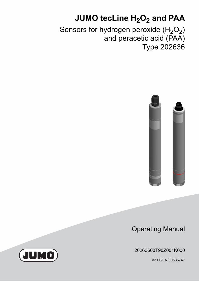
20263600T90Z001K000
V3.00/EN/00585747
JUMO tecLine H2O2 and PAASensors for hydrogen peroxide (H2O2)
and peracetic acid (PAA)Type 202636
Operating Manual

Contents
Contents1 Introduction . . . . . . . . . . . . . . . . . . . . . . . . . . . . . . . . . . . . . . . . . . . . . . . . . . . . 61.1 Safety information . . . . . . . . . . . . . . . . . . . . . . . . . . . . . . . . . . . . . . . . . . . . . . . . . . . . . . . . . . . . 61.1.1 General Information . . . . . . . . . . . . . . . . . . . . . . . . . . . . . . . . . . . . . . . . . . . . . . . . . . . . . . . . . . 61.1.2 Warning symbols. . . . . . . . . . . . . . . . . . . . . . . . . . . . . . . . . . . . . . . . . . . . . . . . . . . . . . . . . . . . . 61.1.3 Note symbols . . . . . . . . . . . . . . . . . . . . . . . . . . . . . . . . . . . . . . . . . . . . . . . . . . . . . . . . . . . . . . . 6
2 Description. . . . . . . . . . . . . . . . . . . . . . . . . . . . . . . . . . . . . . . . . . . . . . . . . . . . . 72.1 Areas of application . . . . . . . . . . . . . . . . . . . . . . . . . . . . . . . . . . . . . . . . . . . . . . . . . . . . . . . . . . 72.2 Design. . . . . . . . . . . . . . . . . . . . . . . . . . . . . . . . . . . . . . . . . . . . . . . . . . . . . . . . . . . . . . . . . . . . . 72.3 Output signal. . . . . . . . . . . . . . . . . . . . . . . . . . . . . . . . . . . . . . . . . . . . . . . . . . . . . . . . . . . . . . . . 72.4 Suitable indicators/transmitters/controllers . . . . . . . . . . . . . . . . . . . . . . . . . . . . . . . . . . . . . . . . . 82.5 Sensor details . . . . . . . . . . . . . . . . . . . . . . . . . . . . . . . . . . . . . . . . . . . . . . . . . . . . . . . . . . . . . . . 92.6 Important information for use . . . . . . . . . . . . . . . . . . . . . . . . . . . . . . . . . . . . . . . . . . . . . . . . . . 112.6.1 Notes for all types . . . . . . . . . . . . . . . . . . . . . . . . . . . . . . . . . . . . . . . . . . . . . . . . . . . . . . . . . . . 112.6.2 Types with valve opening in the membrane cap (202636/55-45, -60, -70, -75 and 202636/
60-60, -70, -80) . . . . . . . . . . . . . . . . . . . . . . . . . . . . . . . . . . . . . . . . . . . . . . . . . . . . . . . . . . . . . 11
3 Identifying the device version . . . . . . . . . . . . . . . . . . . . . . . . . . . . . . . . . . . . 133.1 Nameplate. . . . . . . . . . . . . . . . . . . . . . . . . . . . . . . . . . . . . . . . . . . . . . . . . . . . . . . . . . . . . . . . . 133.2 Order details . . . . . . . . . . . . . . . . . . . . . . . . . . . . . . . . . . . . . . . . . . . . . . . . . . . . . . . . . . . . . . . 143.3 Scope of delivery . . . . . . . . . . . . . . . . . . . . . . . . . . . . . . . . . . . . . . . . . . . . . . . . . . . . . . . . . . . 143.4 Accessories. . . . . . . . . . . . . . . . . . . . . . . . . . . . . . . . . . . . . . . . . . . . . . . . . . . . . . . . . . . . . . . . 15
4 Mounting . . . . . . . . . . . . . . . . . . . . . . . . . . . . . . . . . . . . . . . . . . . . . . . . . . . . . 174.1 Important information . . . . . . . . . . . . . . . . . . . . . . . . . . . . . . . . . . . . . . . . . . . . . . . . . . . . . . . . 174.2 Combination fitting (type 202811/10) . . . . . . . . . . . . . . . . . . . . . . . . . . . . . . . . . . . . . . . . . . . . 194.2.1 Mounting the combination fitting . . . . . . . . . . . . . . . . . . . . . . . . . . . . . . . . . . . . . . . . . . . . . . . . 194.2.2 Installing the sensor . . . . . . . . . . . . . . . . . . . . . . . . . . . . . . . . . . . . . . . . . . . . . . . . . . . . . . . . . 204.3 Flow fitting for membrane-covered sensors (type 202811/30) . . . . . . . . . . . . . . . . . . . . . . . . . 224.3.1 Mounting the fitting . . . . . . . . . . . . . . . . . . . . . . . . . . . . . . . . . . . . . . . . . . . . . . . . . . . . . . . . . . 224.3.2 Installing the sensor . . . . . . . . . . . . . . . . . . . . . . . . . . . . . . . . . . . . . . . . . . . . . . . . . . . . . . . . . 234.4 Flow monitor for disinfection measurands (type 202811/20). . . . . . . . . . . . . . . . . . . . . . . . . . . 244.4.1 Mounting the flow monitor. . . . . . . . . . . . . . . . . . . . . . . . . . . . . . . . . . . . . . . . . . . . . . . . . . . . . 24
5 Electrical connection . . . . . . . . . . . . . . . . . . . . . . . . . . . . . . . . . . . . . . . . . . . 255.1 Sensors with an output signal of 4 to 20 mA (types 202636/55 and /60) . . . . . . . . . . . . . . . . . 255.1.1 General requirements . . . . . . . . . . . . . . . . . . . . . . . . . . . . . . . . . . . . . . . . . . . . . . . . . . . . . . . . 255.1.2 Terminal assignment . . . . . . . . . . . . . . . . . . . . . . . . . . . . . . . . . . . . . . . . . . . . . . . . . . . . . . . . . 255.1.3 Connection . . . . . . . . . . . . . . . . . . . . . . . . . . . . . . . . . . . . . . . . . . . . . . . . . . . . . . . . . . . . . . . . 255.2 Sensors with a digital interface output signal (types 202636/75 and /80). . . . . . . . . . . . . . . . . 275.2.1 General requirements . . . . . . . . . . . . . . . . . . . . . . . . . . . . . . . . . . . . . . . . . . . . . . . . . . . . . . . . 275.2.2 Terminal assignment . . . . . . . . . . . . . . . . . . . . . . . . . . . . . . . . . . . . . . . . . . . . . . . . . . . . . . . . . 275.3 Flow monitoring (combination fitting and flow monitor). . . . . . . . . . . . . . . . . . . . . . . . . . . . . . . 27
Contents
5.3.1 Terminal assignment . . . . . . . . . . . . . . . . . . . . . . . . . . . . . . . . . . . . . . . . . . . . . . . . . . . . . . . . . 275.4 Combination fitting temperature probe . . . . . . . . . . . . . . . . . . . . . . . . . . . . . . . . . . . . . . . . . . . 275.4.1 Terminal assignment . . . . . . . . . . . . . . . . . . . . . . . . . . . . . . . . . . . . . . . . . . . . . . . . . . . . . . . . . 275.5 Example of a measuring section with the sensor type 202636/55 . . . . . . . . . . . . . . . . . . . . . . 285.5.1 General information . . . . . . . . . . . . . . . . . . . . . . . . . . . . . . . . . . . . . . . . . . . . . . . . . . . . . . . . . 285.5.2 Connection example . . . . . . . . . . . . . . . . . . . . . . . . . . . . . . . . . . . . . . . . . . . . . . . . . . . . . . . . . 286 Startup . . . . . . . . . . . . . . . . . . . . . . . . . . . . . . . . . . . . . . . . . . . . . . . . . . . . . . . 296.1 Important notes for screwing the membrane cap on and off. . . . . . . . . . . . . . . . . . . . . . . . . . . 296.2 Initial filling and installation of the membrane cap . . . . . . . . . . . . . . . . . . . . . . . . . . . . . . . . . . 306.2.1 Types with valve opening in the membrane cap (202636/55-45, -60, -70, -75 and 202636/
60-60, -70, -80) . . . . . . . . . . . . . . . . . . . . . . . . . . . . . . . . . . . . . . . . . . . . . . . . . . . . . . . . . . . . . 306.2.2 Types with an internal pressure compensation system (202636/55-81, /60-81, /60-85, /75
and /80). . . . . . . . . . . . . . . . . . . . . . . . . . . . . . . . . . . . . . . . . . . . . . . . . . . . . . . . . . . . . . . . . . . 336.3 Minimum inflow . . . . . . . . . . . . . . . . . . . . . . . . . . . . . . . . . . . . . . . . . . . . . . . . . . . . . . . . . . . . . 356.3.1 Adjusting the minimum inflow (combination fitting and flow monitor) . . . . . . . . . . . . . . . . . . . . 356.4 Settling time . . . . . . . . . . . . . . . . . . . . . . . . . . . . . . . . . . . . . . . . . . . . . . . . . . . . . . . . . . . . . . . 35
7 Maintenance. . . . . . . . . . . . . . . . . . . . . . . . . . . . . . . . . . . . . . . . . . . . . . . . . . . 367.1 Replacing the electrolyte. . . . . . . . . . . . . . . . . . . . . . . . . . . . . . . . . . . . . . . . . . . . . . . . . . . . . . 367.1.1 Types with valve opening in the membrane cap (202636/55-45, -60, -70, -75 and 202636/
60-60, -70, -80) . . . . . . . . . . . . . . . . . . . . . . . . . . . . . . . . . . . . . . . . . . . . . . . . . . . . . . . . . . . . . 367.1.2 Types with an internal pressure compensation system (202636/55-81, /60-81, /60-85, /75
and /80). . . . . . . . . . . . . . . . . . . . . . . . . . . . . . . . . . . . . . . . . . . . . . . . . . . . . . . . . . . . . . . . . . . 397.2 Replacing the membrane cap . . . . . . . . . . . . . . . . . . . . . . . . . . . . . . . . . . . . . . . . . . . . . . . . . . 427.2.1 Types with valve opening in the membrane cap (202636/55-45, -60, -70, -75 and 202636/
60-60, -70, -80) . . . . . . . . . . . . . . . . . . . . . . . . . . . . . . . . . . . . . . . . . . . . . . . . . . . . . . . . . . . . . 427.2.2 Types with an internal pressure compensation system (202636/55-81, /60-81, /60-85, /75
and /80). . . . . . . . . . . . . . . . . . . . . . . . . . . . . . . . . . . . . . . . . . . . . . . . . . . . . . . . . . . . . . . . . . . 457.3 Storage . . . . . . . . . . . . . . . . . . . . . . . . . . . . . . . . . . . . . . . . . . . . . . . . . . . . . . . . . . . . . . . . . . . 487.3.1 Types with valve opening in the membrane cap (202636/55-45, -60, -70, -75 and 202636/
60-60, -70, -80) . . . . . . . . . . . . . . . . . . . . . . . . . . . . . . . . . . . . . . . . . . . . . . . . . . . . . . . . . . . . . 487.3.2 Types with an internal pressure compensation system (202636/55-81, /60-81, /60-85, /75
and /80). . . . . . . . . . . . . . . . . . . . . . . . . . . . . . . . . . . . . . . . . . . . . . . . . . . . . . . . . . . . . . . . . . . 487.4 Consumable material . . . . . . . . . . . . . . . . . . . . . . . . . . . . . . . . . . . . . . . . . . . . . . . . . . . . . . . . 49
8 Calibration . . . . . . . . . . . . . . . . . . . . . . . . . . . . . . . . . . . . . . . . . . . . . . . . . . . . 508.1 General information . . . . . . . . . . . . . . . . . . . . . . . . . . . . . . . . . . . . . . . . . . . . . . . . . . . . . . . . . 508.2 Calibrating with an indicator/controller . . . . . . . . . . . . . . . . . . . . . . . . . . . . . . . . . . . . . . . . . . . 50
9 Overcoming errors and malfunctions . . . . . . . . . . . . . . . . . . . . . . . . . . . . . . 519.1 General troubleshooting . . . . . . . . . . . . . . . . . . . . . . . . . . . . . . . . . . . . . . . . . . . . . . . . . . . . . . 519.2 Specific troubleshooting on the sensor . . . . . . . . . . . . . . . . . . . . . . . . . . . . . . . . . . . . . . . . . . . 53

Contents
9.2.1 Testing the leak-tightness of the membrane cap . . . . . . . . . . . . . . . . . . . . . . . . . . . . . . . . . . . 539.2.2 Electronics test . . . . . . . . . . . . . . . . . . . . . . . . . . . . . . . . . . . . . . . . . . . . . . . . . . . . . . . . . . . . . 539.2.3 Testing the zero point . . . . . . . . . . . . . . . . . . . . . . . . . . . . . . . . . . . . . . . . . . . . . . . . . . . . . . . . 539.2.4 Measurement signal test . . . . . . . . . . . . . . . . . . . . . . . . . . . . . . . . . . . . . . . . . . . . . . . . . . . . . . 549.2.5 Testing the environment . . . . . . . . . . . . . . . . . . . . . . . . . . . . . . . . . . . . . . . . . . . . . . . . . . . . . . 5410 Technical data . . . . . . . . . . . . . . . . . . . . . . . . . . . . . . . . . . . . . . . . . . . . . . . . . 5510.1 Sensors for peracetic acid (PAA) . . . . . . . . . . . . . . . . . . . . . . . . . . . . . . . . . . . . . . . . . . . . . . . 5510.2 Sensors for hydrogen peroxide (H2O2) . . . . . . . . . . . . . . . . . . . . . . . . . . . . . . . . . . . . . . . . . . . 56
11 Annex . . . . . . . . . . . . . . . . . . . . . . . . . . . . . . . . . . . . . . . . . . . . . . . . . . . . . . . . 5811.1 Suitable titration methods . . . . . . . . . . . . . . . . . . . . . . . . . . . . . . . . . . . . . . . . . . . . . . . . . . . . . 58
12 China RoHS . . . . . . . . . . . . . . . . . . . . . . . . . . . . . . . . . . . . . . . . . . . . . . . . . . . 60
1 Introduction
1 Introduction
1.1 Safety information1.1.1 General InformationThis manual contains information that must be observed in the interest of your own safety and to avoidmaterial damage. This information is supported by symbols which are used in this manual as indicated.Please read this manual before starting up the device. Store this manual in a place that is accessible toall users at all times. If difficulties occur during startup, please do not intervene in any way that could jeopardize your warrantyrights!
1.1.2 Warning symbols
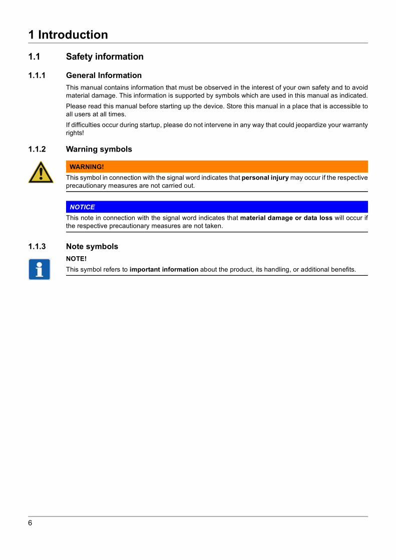
WARNING!This symbol in connection with the signal word indicates that personal injury may occur if the respectiveprecautionary measures are not carried out.
NOTICEThis note in connection with the signal word indicates that material damage or data loss will occur ifthe respective precautionary measures are not taken.
1.1.3 Note symbolsNOTE!This symbol refers to important information about the product, its handling, or additional benefits.
6
2 Description
2 Description
2.1 Areas of applicationThese membrane-covered amperometric sensors are used to measure the concentration of hydrogenperoxide or peracetic acid in aqueous solutions.Typical areas of application are galvanizing plants, the pharmaceutical field, the food and beverage in-dustry, dairies and the chemical industry.The sensors are partially insensitive to chemicals and surfactants, and can be used in media with almostall qualities of water.
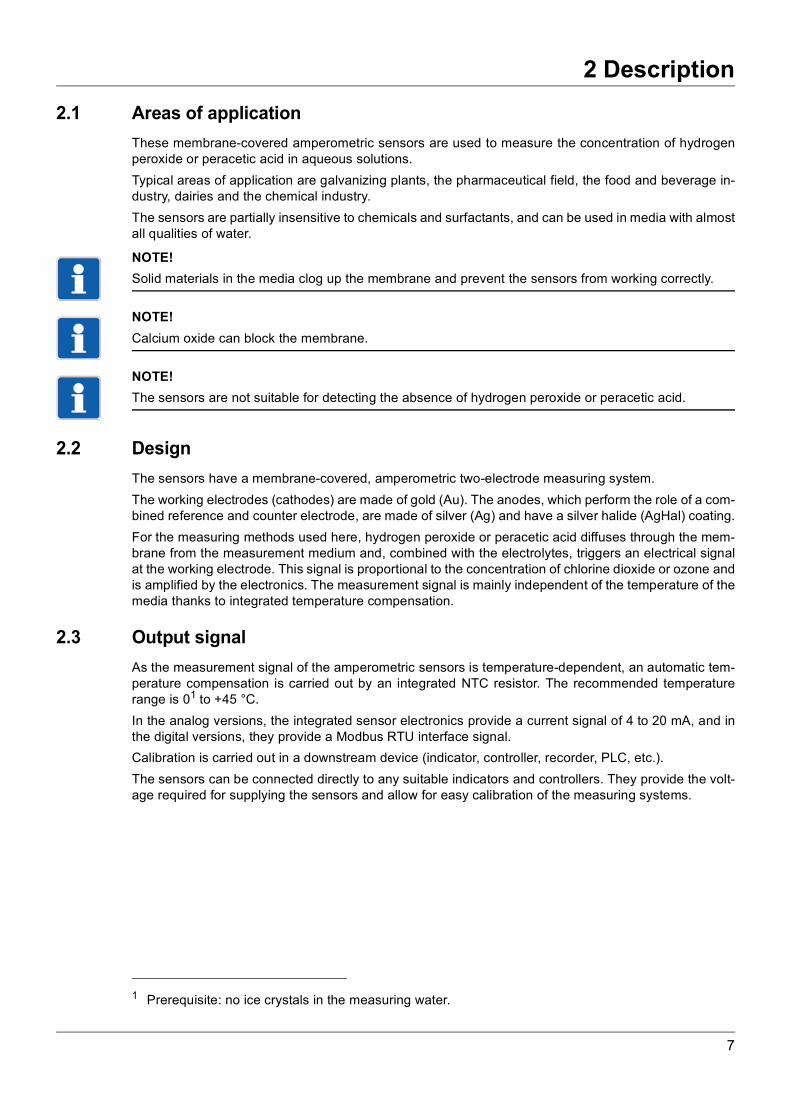
NOTE!Solid materials in the media clog up the membrane and prevent the sensors from working correctly.
NOTE!Calcium oxide can block the membrane.
NOTE!The sensors are not suitable for detecting the absence of hydrogen peroxide or peracetic acid.
2.2 DesignThe sensors have a membrane-covered, amperometric two-electrode measuring system.The working electrodes (cathodes) are made of gold (Au). The anodes, which perform the role of a com-bined reference and counter electrode, are made of silver (Ag) and have a silver halide (AgHal) coating.For the measuring methods used here, hydrogen peroxide or peracetic acid diffuses through the mem-brane from the measurement medium and, combined with the electrolytes, triggers an electrical signalat the working electrode. This signal is proportional to the concentration of chlorine dioxide or ozone andis amplified by the electronics. The measurement signal is mainly independent of the temperature of themedia thanks to integrated temperature compensation.
2.3 Output signalAs the measurement signal of the amperometric sensors is temperature-dependent, an automatic tem-perature compensation is carried out by an integrated NTC resistor. The recommended temperaturerange is 01 to +45 °C.In the analog versions, the integrated sensor electronics provide a current signal of 4 to 20 mA, and inthe digital versions, they provide a Modbus RTU interface signal.Calibration is carried out in a downstream device (indicator, controller, recorder, PLC, etc.).The sensors can be connected directly to any suitable indicators and controllers. They provide the volt-age required for supplying the sensors and allow for easy calibration of the measuring systems.
1 Prerequisite: no ice crystals in the measuring water.
7
2 Description
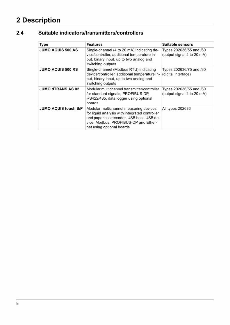
2.4 Suitable indicators/transmitters/controllersType Features Suitable sensorsJUMO AQUIS 500 AS Single-channel (4 to 20 mA) indicating de-
vice/controller, additional temperature in-put, binary input, up to two analog and switching outputs
Types 202636/55 and /60(output signal 4 to 20 mA)
JUMO AQUIS 500 RS Single-channel (Modbus RTU) indicating device/controller, additional temperature in-put, binary input, up to two analog and switching outputs
Types 202636/75 and /80(digital interface)
JUMO dTRANS AS 02 Modular multichannel transmitter/controller for standard signals, PROFIBUS-DP, RS422/485, data logger using optional boards
Types 202636/55 and /60(output signal 4 to 20 mA)
JUMO AQUIS touch S/P Modular multichannel measuring devices for liquid analysis with integrated controller and paperless recorder, USB host, USB de-vice, Modbus, PROFIBUS-DP and Ether-net using optional boards
All types 202636
8
2 Description
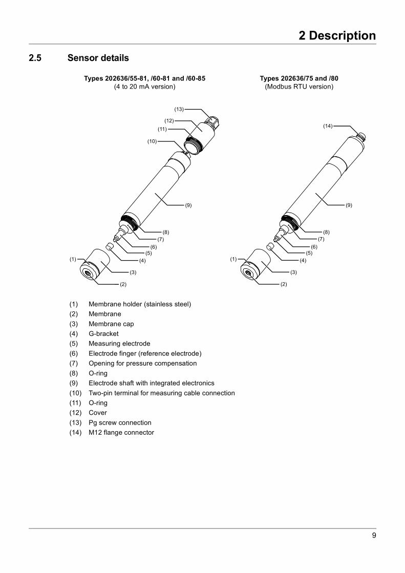
2.5 Sensor detailsTypes 202636/55-81, /60-81 and /60-85(4 to 20 mA version)
Types 202636/75 and /80(Modbus RTU version)
(1) Membrane holder (stainless steel)(2) Membrane(3) Membrane cap(4) G-bracket(5) Measuring electrode(6) Electrode finger (reference electrode)(7) Opening for pressure compensation(8) O-ring(9) Electrode shaft with integrated electronics(10) Two-pin terminal for measuring cable connection(11) O-ring(12) Cover(13) Pg screw connection(14) M12 flange connector
(1)
(2)
(3)
(4)
(5)(6)
(7)
(8)
(9)
(10)
(11)
(12)
(13)
(1)
(2)
(3)
(4)
(5)(6)
(7)
(8)
(9)
(14)
9
2 Description
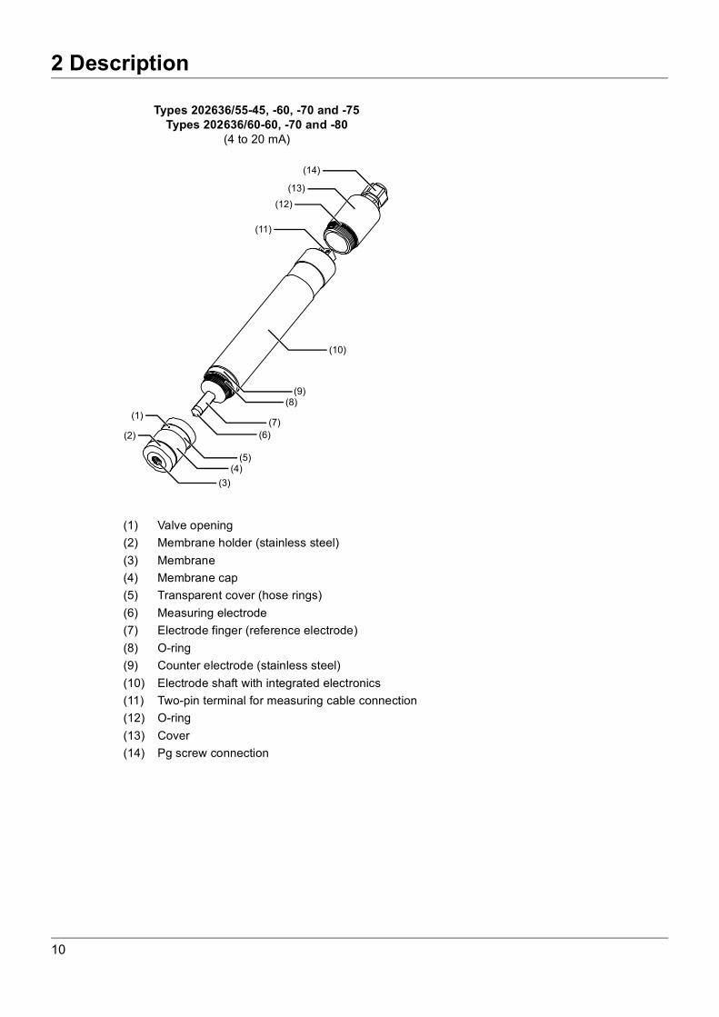
Types 202636/55-45, -60, -70 and -75Types 202636/60-60, -70 and -80
(4 to 20 mA)
(1) Valve opening(2) Membrane holder (stainless steel)(3) Membrane(4) Membrane cap(5) Transparent cover (hose rings)(6) Measuring electrode(7) Electrode finger (reference electrode)(8) O-ring(9) Counter electrode (stainless steel)(10) Electrode shaft with integrated electronics(11) Two-pin terminal for measuring cable connection(12) O-ring(13) Cover(14) Pg screw connection
(3)
(4)(5)
(6)
(7)
(8)
(10)
(1)
(11)
(12)
(13)
(14)
(2)
(9)
10
2 Description
2.6 Important information for use2.6.1 Notes for all types
NOTICE
Unsuitable measurement media may produce incorrect measurement results.Using the sensors to measure contaminated media (dirt particles, foreign objects, fibers, etc.) may leadto incorrect measurement results. In order to ensure error-free measurements, the measurement media must be visibly clean. A pre-
filter must also be used, as required.
NOTICE
An unsuitable measuring environment may produce incorrect measurement results.Using the sensors without the use of suitable flow fittings will lead to incorrect measurement results. In order to ensure error-free measurements, the sensors must be installed in suitable flow fittings,
see chapter 4.2 "Combination fitting (type 202811/10)", page 19 or chapter 4.3 "Flow fitting for mem-brane-covered sensors (type 202811/30)", page 22.
NOTICE
Incorrect handling may cause damage to the membrane caps.Screwing an unfilled membrane cap fully onto the sensor before startup may cause mechanical damageto the membrane. In addition, screwing on a filled membrane cap without placing the sensor into themeasurement media can cause salt or gel residues to be deposited. Screwing on the membrane cap without then starting up the sensor should be avoided.
NOTICE
The membranes may be damaged by high pressure.Operating the sensors with increased pressure may cause the membranes to rip. The sensors should be operated under as little pressure as possible, with the measurement media
able to flow freely. If this is not possible, the sensors can be operated under a constant pressure ofup to 1 bar (relative pressure) or 2 bar (absolute pressure). Fluctuations in pressure must be avoid-ed.
2.6.2 Types with valve opening in the membrane cap (202636/55-45, -60, -70, -75 and 202636/60-60, -70, -80)The measurement water must not contain any surfactants (contained in some cleaning agents and dis-infectants). Surfactants may infiltrate the valve cover of the membrane cap. It can therefore no longer beguaranteed that the sensors will work correctly.The sensors for hydrogen peroxide and peracetic acid with a digital interface and internal pressure com-pensation system (types 202636/75 and 202636/80) provide an alternative for measurement solutionscontaining surfactants.
11
2 Description
NOTICE
Irritating substances may produce incorrect measurement results.Using the sensors to measure media containing surfactants may lead to incorrect measurement results. In order to ensure error-free measurements, the measurement media must not contain surfactants
(surface-active substances e.g. from detergents, cleaning agents or disinfectants).
NOTICE
Harmful substances may lead to incorrect measurement results and cause damage to the mem-brane caps.Using the sensors to measure media containing hydrophobic substances may lead to incorrect measure-ment results. Hydrophobic substances can damage the membrane caps. In order to ensure error-free measurements, the measurement media must not contain hydrophobic
substances (e.g. oil or grease).
12
3 Identifying the device version
3 Identifying the device version
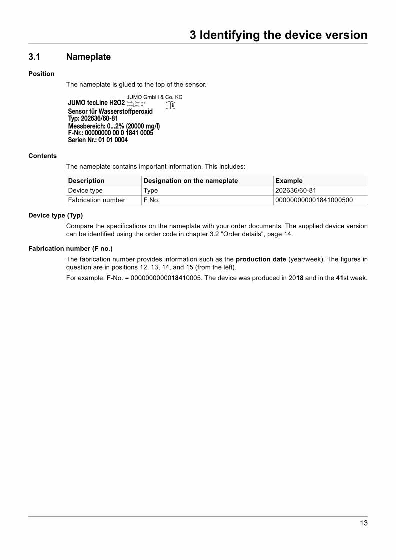
3.1 NameplatePositionThe nameplate is glued to the top of the sensor.
ContentsThe nameplate contains important information. This includes:
Device type (Typ)Compare the specifications on the nameplate with your order documents. The supplied device versioncan be identified using the order code in chapter 3.2 "Order details", page 14.
Fabrication number (F no.)The fabrication number provides information such as the production date (year/week). The figures inquestion are in positions 12, 13, 14, and 15 (from the left).For example: F-No. = 0000000000018410005. The device was produced in 2018 and in the 41st week.
JUMO tecLine H2O2Sensor für WasserstoffperoxidTyp: 202636/60-81Messbereich: 0...2% (20000 mg/l)F-Nr.: 00000000 00 0 1841 0005Serien Nr.: 01 01 0004
JUMO GmbH & Co. KGFulda, Germanywww.jumo.net
Description Designation on the nameplate ExampleDevice type Type 202636/60-81Fabrication number F No. 000000000001841000500
13
3 Identifying the device version
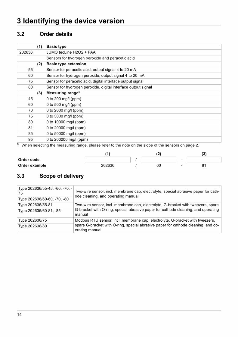
3.2 Order details3.3 Scope of delivery
(1) Basic type202636 JUMO tecLine H2O2 + PAA
Sensors for hydrogen peroxide and peracetic acid(2) Basic type extension
55 Sensor for peracetic acid, output signal 4 to 20 mA60 Sensor for hydrogen peroxide, output signal 4 to 20 mA75 Sensor for peracetic acid, digital interface output signal80 Sensor for hydrogen peroxide, digital interface output signal
(3) Measuring rangea
45 0 to 200 mg/l (ppm)60 0 to 500 mg/l (ppm)70 0 to 2000 mg/l (ppm)75 0 to 5000 mg/l (ppm)80 0 to 10000 mg/l (ppm)81 0 to 20000 mg/l (ppm)85 0 to 50000 mg/l (ppm)95 0 to 200000 mg/l (ppm)
a When selecting the measuring range, please refer to the note on the slope of the sensors on page 2.
(1) (2) (3)Order code / -Order example 202636 / 60 - 81
Type 202636/55-45, -60, -70, -75 Two-wire sensor, incl. membrane cap, electrolyte, special abrasive paper for cath-
ode cleaning, and operating manualType 202636/60-60, -70, -80Type 202636/55-81 Two-wire sensor, incl. membrane cap, electrolyte, G-bracket with tweezers, spare
G-bracket with O-ring, special abrasive paper for cathode cleaning, and operating manual
Type 202636/60-81, -85
Type 202636/75 Modbus RTU sensor, incl. membrane cap, electrolyte, G-bracket with tweezers, spare G-bracket with O-ring, special abrasive paper for cathode cleaning, and op-erating manual
Type 202636/80
14

3 Identifying the device version
3.4 AccessoriesFittingsDesignation Part no.Combination fitting for mounting several electrochemical sensorsa 00607325Individual fitting for mounting a membrane-covered sensor 00392611Mounting bracket for individual fitting 00455706Flow monitor for monitoring the minimum inflowb 00605507
a With integrated flow monitor, mini ball valve included.b For flow monitoring in connection with the individual fitting.
Connecting cables for sensors with a digital interfaceDesignation Part no.1.5 m connecting cable, 5-pin M12 connector, A-coded on the ferrules 006383335 m connecting cable, 5-pin M12 connector, A-coded on the ferrules 0063833710 m connecting cable, 5-pin M12 connector, A-coded on the ferrules 00638341
Suitable transmitters/controllersDesignation Part no.JUMO AQUIS 500 ASa, type 202568/20-888-888-888-310-310-23/000(for further versions, please refer to data sheet 202568)
00528718
JUMO AQUIS 500 RSb, type 202569/20-654-888-888-310-310-23/000(for further versions, please refer to data sheet 202569)
00602275
JUMO dTRANS AS 02a, type: 202553/01-8-01-4-0-00-23/000(fur further versions, please refer to data sheet 202553)
00550842
JUMO AQUIS touch S/Pc Refer to data sheet 202580/81
a For types 202636/55 and /60.b For types 202636/75 and /80.c For all types 202636.
15
3 Identifying the device version
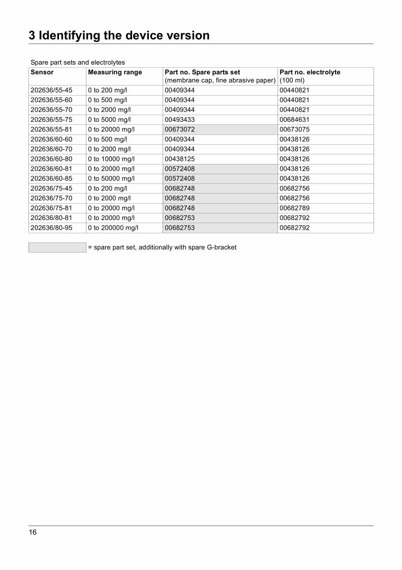
Spare part sets and electrolytesSensor Measuring range Part no. Spare parts set
(membrane cap, fine abrasive paper)Part no. electrolyte(100 ml)
202636/55-45 0 to 200 mg/l 00409344 00440821202636/55-60 0 to 500 mg/l 00409344 00440821202636/55-70 0 to 2000 mg/l 00409344 00440821202636/55-75 0 to 5000 mg/l 00493433 00684631202636/55-81 0 to 20000 mg/l 00673072 00673075202636/60-60 0 to 500 mg/l 00409344 00438126202636/60-70 0 to 2000 mg/l 00409344 00438126202636/60-80 0 to 10000 mg/l 00438125 00438126202636/60-81 0 to 20000 mg/l 00572408 00438126202636/60-85 0 to 50000 mg/l 00572408 00438126202636/75-45 0 to 200 mg/l 00682748 00682756202636/75-70 0 to 2000 mg/l 00682748 00682756202636/75-81 0 to 20000 mg/l 00682748 00682789202636/80-81 0 to 20000 mg/l 00682753 00682792202636/80-95 0 to 200000 mg/l 00682753 00682792
= spare part set, additionally with spare G-bracket
16
4 Mounting
4 Mounting
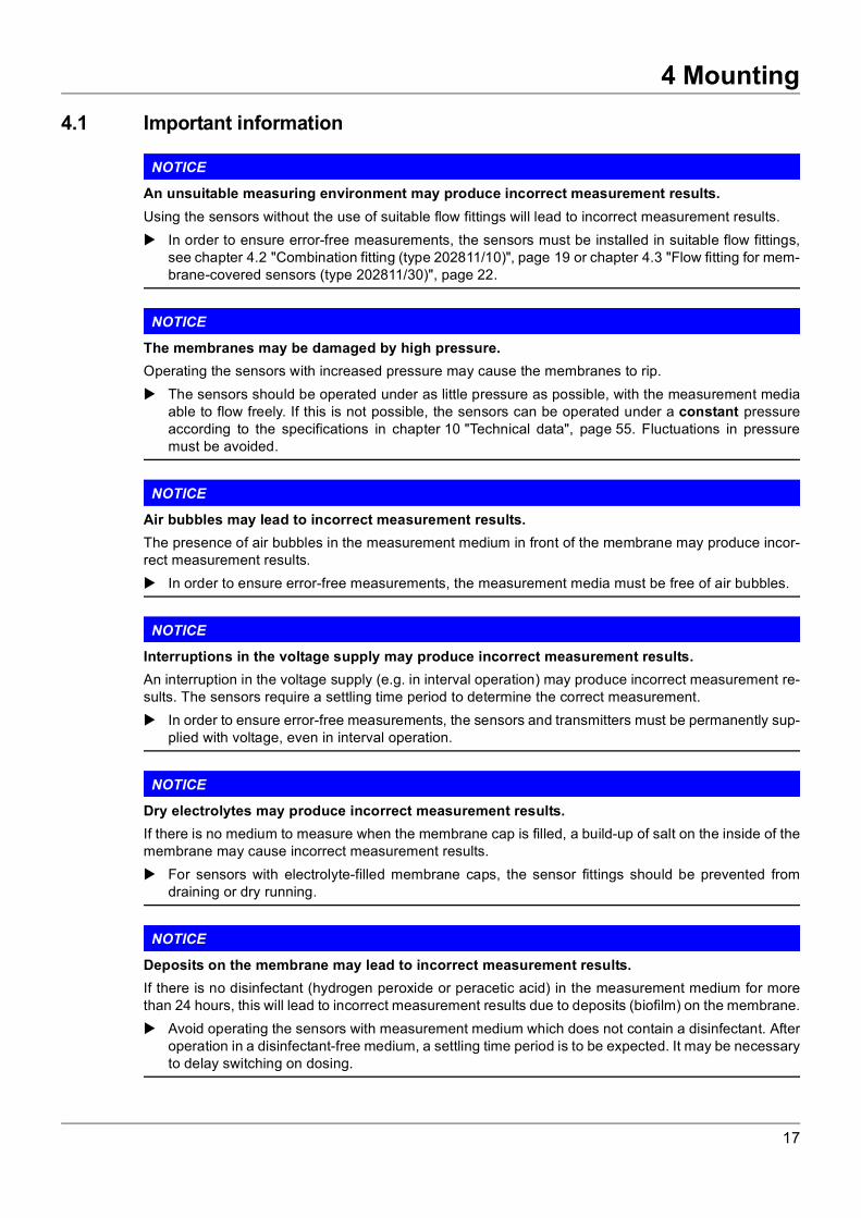
4.1 Important informationNOTICE
An unsuitable measuring environment may produce incorrect measurement results.Using the sensors without the use of suitable flow fittings will lead to incorrect measurement results. In order to ensure error-free measurements, the sensors must be installed in suitable flow fittings,
see chapter 4.2 "Combination fitting (type 202811/10)", page 19 or chapter 4.3 "Flow fitting for mem-brane-covered sensors (type 202811/30)", page 22.
NOTICE
The membranes may be damaged by high pressure.Operating the sensors with increased pressure may cause the membranes to rip. The sensors should be operated under as little pressure as possible, with the measurement media
able to flow freely. If this is not possible, the sensors can be operated under a constant pressureaccording to the specifications in chapter 10 "Technical data", page 55. Fluctuations in pressuremust be avoided.
NOTICE
Air bubbles may lead to incorrect measurement results.The presence of air bubbles in the measurement medium in front of the membrane may produce incor-rect measurement results. In order to ensure error-free measurements, the measurement media must be free of air bubbles.
NOTICE
Interruptions in the voltage supply may produce incorrect measurement results.An interruption in the voltage supply (e.g. in interval operation) may produce incorrect measurement re-sults. The sensors require a settling time period to determine the correct measurement. In order to ensure error-free measurements, the sensors and transmitters must be permanently sup-
plied with voltage, even in interval operation.
NOTICE
Dry electrolytes may produce incorrect measurement results.If there is no medium to measure when the membrane cap is filled, a build-up of salt on the inside of themembrane may cause incorrect measurement results. For sensors with electrolyte-filled membrane caps, the sensor fittings should be prevented from
draining or dry running.
NOTICE
Deposits on the membrane may lead to incorrect measurement results.If there is no disinfectant (hydrogen peroxide or peracetic acid) in the measurement medium for morethan 24 hours, this will lead to incorrect measurement results due to deposits (biofilm) on the membrane. Avoid operating the sensors with measurement medium which does not contain a disinfectant. After
operation in a disinfectant-free medium, a settling time period is to be expected. It may be necessaryto delay switching on dosing.
17
4 Mounting
NOTICE
Impurities may produce incorrect measurement results.Using the sensors to measure media containing oxidants, reducing agents or corrosion protection agentsmay lead to incorrect measurement results. Oxidizing agents, reducing agents, corrosion inhibitors, and substances which result in cross sensi-
tivities with the sensors (see information in chapter 10 "Technical data", page 55) must be avoidedin the measurement medium.
NOTE!If no disinfectant is dosed over a long period of time, the sensors must be disconnected from the trans-mitter/controller, removed and stored correctly; please refer to chapter 7.3 "Storage", page 48.
18

4 Mounting
4.2 Combination fitting (type 202811/10)4.2.1 Mounting the combination fittingThe combination fitting can be mounted on a wall or an installation panel with the mounting holes (1)using two commercially available M5 cylinder head screws (dia. 5.5 mm, countersink according to DIN974-1: dia. 11 mm, 5 mm deep, not included in the scope of delivery).
(1) Mounting hole for cylinder head screws M5 (dia. 5.5 mm; countersink: dia. 11 mm, 5 mm deep)(2) Valve insert for flow control(3) Inductive proximity sensora(flow monitoring), M12 x 1 thread(4) Floating body for flow monitoringa
(5) Sealing screw M8(6) Extension for M8 sealing screw(7) Sealing screw G 3/8(8) Mounting closed with dummy plug for pH/Redox sensor with Pg 13.5 thread(9) Mounting for membrane-covered sensor with dia. 25 mm(10) Hose connection for measuring water outflow, connection G 1/4, for hose 6 × 8
(inner dia. 6 mm, outer dia. 8 mm)(11) M8 ground roda
(6)
(7)
(8) (8)
(10)
(13)
(11)(12)(14)(15)
(9)
19

4 Mounting
4.2.2 Installing the sensor
Overview
(12) Sealing screw G 1/4 (opening for optional mini ball valve for sampling)(13) Indicator for sensor immersion depth(14) Temperature probea
(15) Hose connection for measuring water inflow, connection to fitting G 1/4,for hose 6 × 8 (inner dia. 6 mm, outer dia. 8 mm)
a optionally
(1) Mounting for pH/Redox sensors (7) Pressure ring(2) Pg 13.5 pressure screw (8) Stepped collar(3) Mounting for membrane-covered sensor (9) O-Ring(4) Union nut (10) Mark for sensor immersion depth(5) Membrane-covered sensor (11) Mark for floating body height(6) Sensor slot
(8)
(7)
(9)
20
4 Mounting
InstallationNOTICE
Leaks due to incorrect installationPollutants on the thread of the union nut (4), the pressure ring (7), the stepped collar (8), the O-ring (9),or a hardened O-ring can cause the fitting to leak when the sensor (5) is installed. When assembling or installing the sensor, make sure that the O-rings and threads are clean and in
good working order.
1. Before installing the sensors, make sure that the system is depressurized.
2. Close the shut-off valves in the inflow and outflow of the fitting.
3. Unscrew the union nut (4).
4. Remove the stepped collar (8). The pressure ring (7) and the O-ring (9) remain in the sensor mount-ing (3).
5. Slide the stepped collar from above onto the sensor (5) until it engages in the sensor slot (6). Thestep collar should now rotate easily on the sensor housing.
6. Insert the sensor with the mounted stepped collar into the sensor mounting (3) as far as it will go.
7. Screw the union nut (4) back onto the sensor mounting and tighten it hand-tight.
21

4 Mounting
4.3 Flow fitting for membrane-covered sensors (type 202811/30)4.3.1 Mounting the fittingThe flow fitting can be mounted to a wall or an installation panel using an optional mounting bracket (partno.: 00455706).
(1) Sensor(2) Mounting bracket (optional)(3) Connection G 1/4, for hose Ø 8 mm × 6 mm(4) Fitting(5) Removable measuring vessel (inspection glass)
150
104
5.5
23
4
19
.5
15
12
0
(1)
(2)
(3)
(4)
(5)
22
4 Mounting
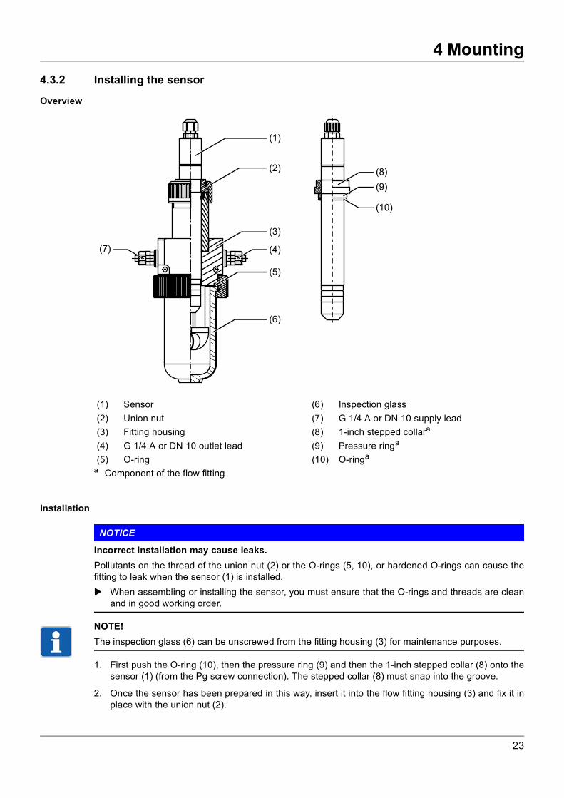
4.3.2 Installing the sensorOverview
Installation
NOTICE
Incorrect installation may cause leaks.Pollutants on the thread of the union nut (2) or the O-rings (5, 10), or hardened O-rings can cause thefitting to leak when the sensor (1) is installed. When assembling or installing the sensor, you must ensure that the O-rings and threads are clean
and in good working order.
NOTE!The inspection glass (6) can be unscrewed from the fitting housing (3) for maintenance purposes.
1. First push the O-ring (10), then the pressure ring (9) and then the 1-inch stepped collar (8) onto thesensor (1) (from the Pg screw connection). The stepped collar (8) must snap into the groove.
2. Once the sensor has been prepared in this way, insert it into the flow fitting housing (3) and fix it inplace with the union nut (2).
(1) Sensor (6) Inspection glass(2) Union nut (7) G 1/4 A or DN 10 supply lead(3) Fitting housing (8) 1-inch stepped collara
a Component of the flow fitting
(4) G 1/4 A or DN 10 outlet lead (9) Pressure ringa
(5) O-ring (10) O-ringa
(1)
(2)
(3)
(4)
(5)
(6)
(7)
(8)
(9)
(10)
23
4 Mounting
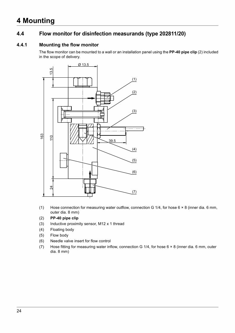
4.4 Flow monitor for disinfection measurands (type 202811/20)4.4.1 Mounting the flow monitorThe flow monitor can be mounted to a wall or an installation panel using the PP-40 pipe clip (2) includedin the scope of delivery.
(1) Hose connection for measuring water outflow, connection G 1/4, for hose 6 × 8 (inner dia. 6 mm, outer dia. 8 mm)
(2) PP-40 pipe clip(3) Inductive proximity sensor, M12 x 1 thread(4) Floating body(5) Flow body(6) Needle valve insert for flow control(7) Hose fitting for measuring water inflow, connection G 1/4, for hose 6 × 8 (inner dia. 6 mm, outer
dia. 8 mm)
16
3
11
01
3.5
Ø 13.5
24
39.5
(1)
(2)
(3)
(4)
(5)
(6)
(7)
24
5 Electrical connection
5 Electrical connection
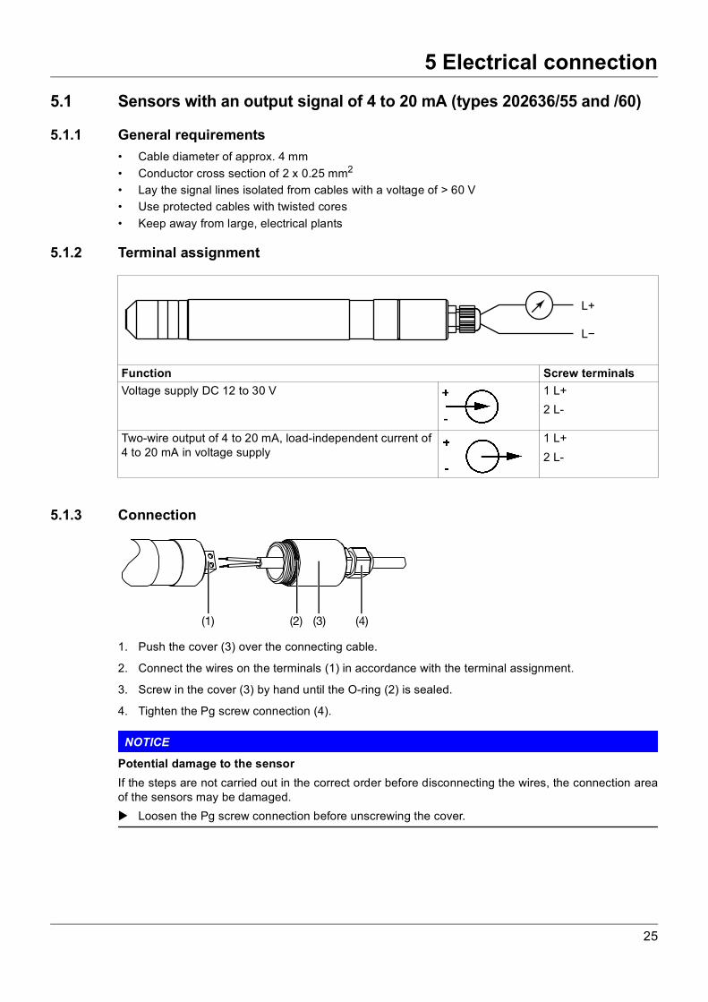
5.1 Sensors with an output signal of 4 to 20 mA (types 202636/55 and /60)5.1.1 General requirements• Cable diameter of approx. 4 mm• Conductor cross section of 2 x 0.25 mm2
• Lay the signal lines isolated from cables with a voltage of > 60 V• Use protected cables with twisted cores• Keep away from large, electrical plants
5.1.2 Terminal assignment
5.1.3 Connection
1. Push the cover (3) over the connecting cable.
2. Connect the wires on the terminals (1) in accordance with the terminal assignment.
3. Screw in the cover (3) by hand until the O-ring (2) is sealed.
4. Tighten the Pg screw connection (4).
NOTICE
Potential damage to the sensorIf the steps are not carried out in the correct order before disconnecting the wires, the connection areaof the sensors may be damaged. Loosen the Pg screw connection before unscrewing the cover.
Function Screw terminalsVoltage supply DC 12 to 30 V 1 L+
2 L-
Two-wire output of 4 to 20 mA, load-independent current of 4 to 20 mA in voltage supply
1 L+2 L-
L+
L
(1) (2) (3) (4)
25
5 Electrical connection
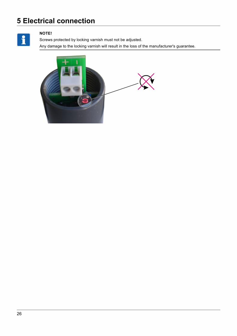
NOTE!Screws protected by locking varnish must not be adjusted.Any damage to the locking varnish will result in the loss of the manufacturer's guarantee.26
5 Electrical connection
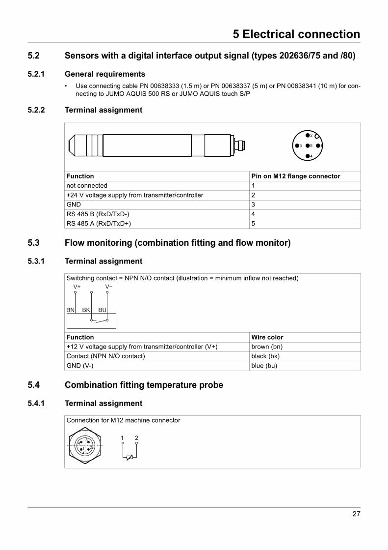
5.2 Sensors with a digital interface output signal (types 202636/75 and /80)5.2.1 General requirements• Use connecting cable PN 00638333 (1.5 m) or PN 00638337 (5 m) or PN 00638341 (10 m) for con-
necting to JUMO AQUIS 500 RS or JUMO AQUIS touch S/P
5.2.2 Terminal assignment
5.3 Flow monitoring (combination fitting and flow monitor)
5.3.1 Terminal assignment
5.4 Combination fitting temperature probe
5.4.1 Terminal assignment
Function Pin on M12 flange connectornot connected 1+24 V voltage supply from transmitter/controller 2GND 3RS 485 B (RxD/TxD-) 4RS 485 A (RxD/TxD+) 5
Switching contact = NPN N/O contact (illustration = minimum inflow not reached)
Function Wire color+12 V voltage supply from transmitter/controller (V+) brown (bn)Contact (NPN N/O contact) black (bk)GND (V-) blue (bu)
Connection for M12 machine connector
27
5 Electrical connection
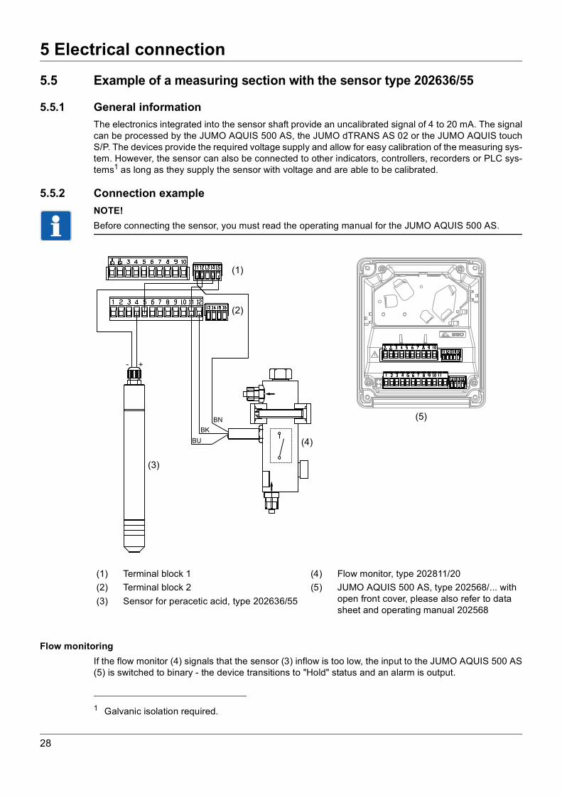
5.5 Example of a measuring section with the sensor type 202636/555.5.1 General informationThe electronics integrated into the sensor shaft provide an uncalibrated signal of 4 to 20 mA. The signalcan be processed by the JUMO AQUIS 500 AS, the JUMO dTRANS AS 02 or the JUMO AQUIS touchS/P. The devices provide the required voltage supply and allow for easy calibration of the measuring sys-tem. However, the sensor can also be connected to other indicators, controllers, recorders or PLC sys-tems1 as long as they supply the sensor with voltage and are able to be calibrated.
5.5.2 Connection exampleNOTE!Before connecting the sensor, you must read the operating manual for the JUMO AQUIS 500 AS.
Flow monitoringIf the flow monitor (4) signals that the sensor (3) inflow is too low, the input to the JUMO AQUIS 500 AS(5) is switched to binary - the device transitions to "Hold" status and an alarm is output.
1 Galvanic isolation required.
(1) Terminal block 1 (4) Flow monitor, type 202811/20(2) Terminal block 2 (5) JUMO AQUIS 500 AS, type 202568/... with
open front cover, please also refer to data sheet and operating manual 202568
(3) Sensor for peracetic acid, type 202636/55
+-
BN
BK
BU
(1)
(2)
(3)
(4)
(5)
28

6 Startup
6 Startup
6.1 Important notes for screwing the membrane cap on and offExample: type 202636/55
NOTICE
Damage to the membrane due to unscrewing the membrane holder.Unscrewing the membrane holder destroys the membrane! Grip the gray plastic part of the membrane cap when unscrewing it, not the metallic membrane hold-
er.
NOTICE
Touching the electrode finger may damage itTouching and contaminating the electrode finger can damage it, making the sensor unusable. Do not touch the electrode finger when carrying out any of the following steps. Carry out the steps
exactly as they are described.
NOTICE
Damage to the membrane due to overpressure or underpressure1
The membrane is extremely sensitive. Screwing the membrane cap on and off can create overpressureor underpressure in the cap which can damage the membrane. Closely follow the instructions for unscrewing and screwing on the membrane cap
(chapter 6.1 "Important notes for screwing the membrane cap on and off", page 29).
NOTICE
Damage to the membrane due to mechanical influencesWhen the sensor is ready to take a measurement (membrane cap fully screwed on), the distance be-tween the electrode finger and the membrane is extremely small. Pushing the tip against the sensor candamage the membrane. The membrane cap must only be screwed onto the sensor immediately before inserting it into a fit-
ting.
NOTE!In order for the sensor to function correctly, the membrane must be fully screwed onto the sensor. Thefirst screw-in resistance is the sealing O-ring. The membrane cap must be screwed on further until itcomes into contact with the sensor shaft.
(1) Sensor shaft(2) O-ring(3) Electrode finger(4) Membrane cap(5) Membrane holder(6) Membrane
(1) (3)(2) (4) (5) (6)
1 Does not apply to the types 202636/75 and /80 as well as to the types 202636/55-81 and /60-81.These types have an internal pressure compensation system that equalizes pressure fluctuationswhen unscrewing and screwing the membrane cap.
29
6 Startup
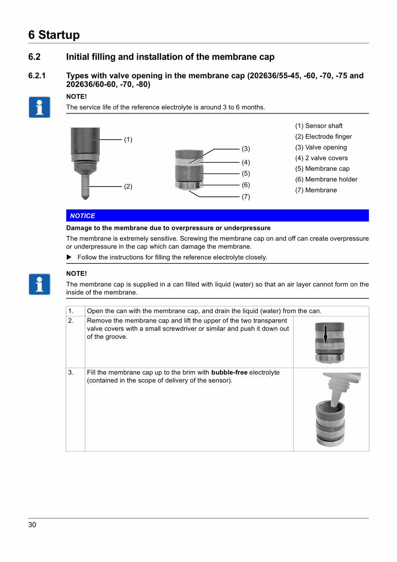
6.2 Initial filling and installation of the membrane cap6.2.1 Types with valve opening in the membrane cap (202636/55-45, -60, -70, -75 and 202636/60-60, -70, -80)NOTE!The service life of the reference electrolyte is around 3 to 6 months.
NOTICE
Damage to the membrane due to overpressure or underpressureThe membrane is extremely sensitive. Screwing the membrane cap on and off can create overpressureor underpressure in the cap which can damage the membrane. Follow the instructions for filling the reference electrolyte closely.
NOTE!The membrane cap is supplied in a can filled with liquid (water) so that an air layer cannot form on theinside of the membrane.
(1) Sensor shaft(2) Electrode finger(3) Valve opening(4) 2 valve covers(5) Membrane cap(6) Membrane holder(7) Membrane
(1)
(2)
(3)
(4)
(5)
(7)
(6)
1. Open the can with the membrane cap, and drain the liquid (water) from the can.2. Remove the membrane cap and lift the upper of the two transparent
valve covers with a small screwdriver or similar and push it down out of the groove.
3. Fill the membrane cap up to the brim with bubble-free electrolyte (contained in the scope of delivery of the sensor).
30
6 Startup
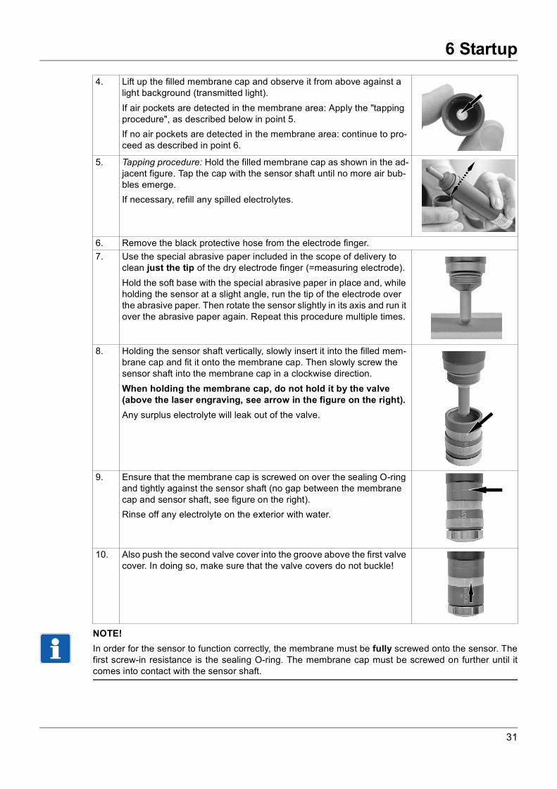
NOTE!In order for the sensor to function correctly, the membrane must be fully screwed onto the sensor. Thefirst screw-in resistance is the sealing O-ring. The membrane cap must be screwed on further until itcomes into contact with the sensor shaft.
4. Lift up the filled membrane cap and observe it from above against a light background (transmitted light).If air pockets are detected in the membrane area: Apply the "tapping procedure", as described below in point 5.If no air pockets are detected in the membrane area: continue to pro-ceed as described in point 6.
5. Tapping procedure: Hold the filled membrane cap as shown in the ad-jacent figure. Tap the cap with the sensor shaft until no more air bub-bles emerge.If necessary, refill any spilled electrolytes.
6. Remove the black protective hose from the electrode finger.7. Use the special abrasive paper included in the scope of delivery to
clean just the tip of the dry electrode finger (=measuring electrode).Hold the soft base with the special abrasive paper in place and, while holding the sensor at a slight angle, run the tip of the electrode over the abrasive paper. Then rotate the sensor slightly in its axis and run it over the abrasive paper again. Repeat this procedure multiple times.
8. Holding the sensor shaft vertically, slowly insert it into the filled mem-brane cap and fit it onto the membrane cap. Then slowly screw the sensor shaft into the membrane cap in a clockwise direction.When holding the membrane cap, do not hold it by the valve (above the laser engraving, see arrow in the figure on the right).Any surplus electrolyte will leak out of the valve.
9. Ensure that the membrane cap is screwed on over the sealing O-ring and tightly against the sensor shaft (no gap between the membrane cap and sensor shaft, see figure on the right).Rinse off any electrolyte on the exterior with water.
10. Also push the second valve cover into the groove above the first valve cover. In doing so, make sure that the valve covers do not buckle!
31
6 Startup
NOTICE
Damage to the membrane due to mechanical influencesWhen the sensor is ready to take a measurement (membrane cap fully screwed on), the distance be-tween the electrode finger and the membrane is extremely small. Pushing the tip against the sensor candamage the membrane. Only commission the sensor immediately before inserting it into a fitting.
32
6 Startup
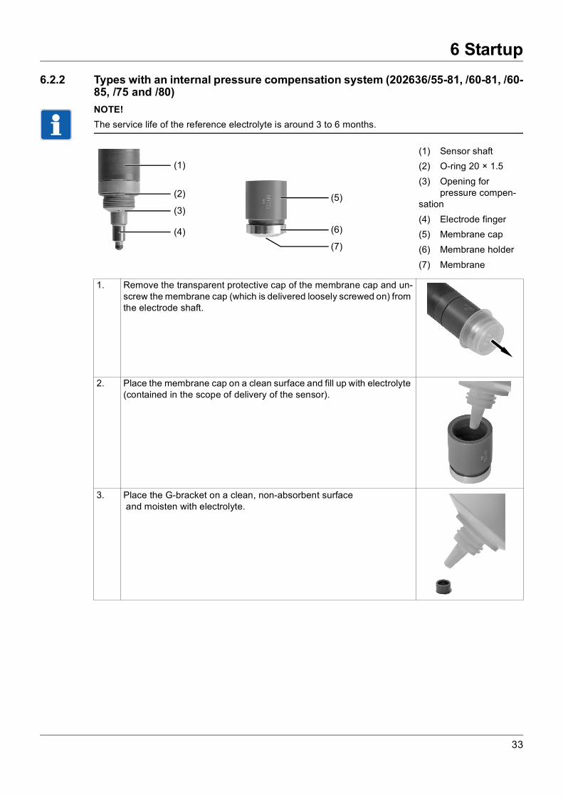
6.2.2 Types with an internal pressure compensation system (202636/55-81, /60-81, /60-85, /75 and /80)NOTE!The service life of the reference electrolyte is around 3 to 6 months.
(1) Sensor shaft(2) O-ring 20 × 1.5(3) Opening for
pressure compen-sation(4) Electrode finger(5) Membrane cap(6) Membrane holder(7) Membrane
1. Remove the transparent protective cap of the membrane cap and un-screw the membrane cap (which is delivered loosely screwed on) from the electrode shaft.
2. Place the membrane cap on a clean surface and fill up with electrolyte (contained in the scope of delivery of the sensor).
3. Place the G-bracket on a clean, non-absorbent surface and moisten with electrolyte.
(1)
(4)
(5)
(7)
(6)
(3)
(2)
33

6 Startup
NOTE!In order for the sensor to function correctly, the membrane must be fully and tightly screwed onto thesensor.
NOTICE
Damage to the membrane due to mechanical influencesWhen the sensor is ready to take a measurement (membrane cap fully screwed on), the distance be-tween the electrode finger and the membrane is extremely small. Pushing the tip against the sensor candamage the membrane. Only commission the sensor immediately before inserting it into a fitting.
4. Use the tweezers included in the scope of delivery to pick up the G-bracket moistened with electrolyte.Use the tweezers to insert and lower the G-bracket into the center of the filled membrane cap until it is incorporated into the recess in the middle of the membrane cap and sits there tightly. Then carefully pull out the tweezers again.The G-bracket remains in the membrane cap.
5. Use the special abrasive paper included in the scope of delivery to clean just the tip of the dry electrode finger (=working electrode).To do so, hold the special abrasive paper in place by one corner, and, while holding the measuring cell vertically, run the tip of the electrode over the abrasive paper two or three times.
6. Holding the electrode shaft vertically, fit it into the filled membrane cap with the inserted G-bracket. Then slowly screw the electrode shaft into the membrane cap in a clockwise direction (by hand) in a vertical po-sition.
7. Make sure that the red O-ring 20 × 1.5 is fitted perfectly (membrane cap sealed).Screw the membrane cap (by hand) tightly against the electrode shaft. The red O-ring 20 × 1.5 mm is pressed in. After this point, no more electrolyte may leak out of the sensor. The membrane or mem-brane disk is curved outward by the electrolyte finger - so do not push it!Rinse off any electrolyte on the exterior with water.
34
6 Startup
6.3 Minimum inflowNOTE!The flow rate from the measurement medium must be at least 15 cm/s in order for the sensor to workcorrectly. The minimum flow rate in the combination fitting or the flow fitting is 30 l/h. Values measuredby the sensors below the minimum inflow speed are too low. This can cause dangerous overdosage ina connected regulating system. If values are measured above the minimum inflow speed, the measure-ment signal is only marginally influenced by the inflow speed.
6.3.1 Adjusting the minimum inflow (combination fitting and flow monitor)
6.4 Settling timeNOTE!The sensors will only measure a constant value at the end of the settling time and can then be calibrated.
On the day after the initial startup, the calibration procedure should be repeated.
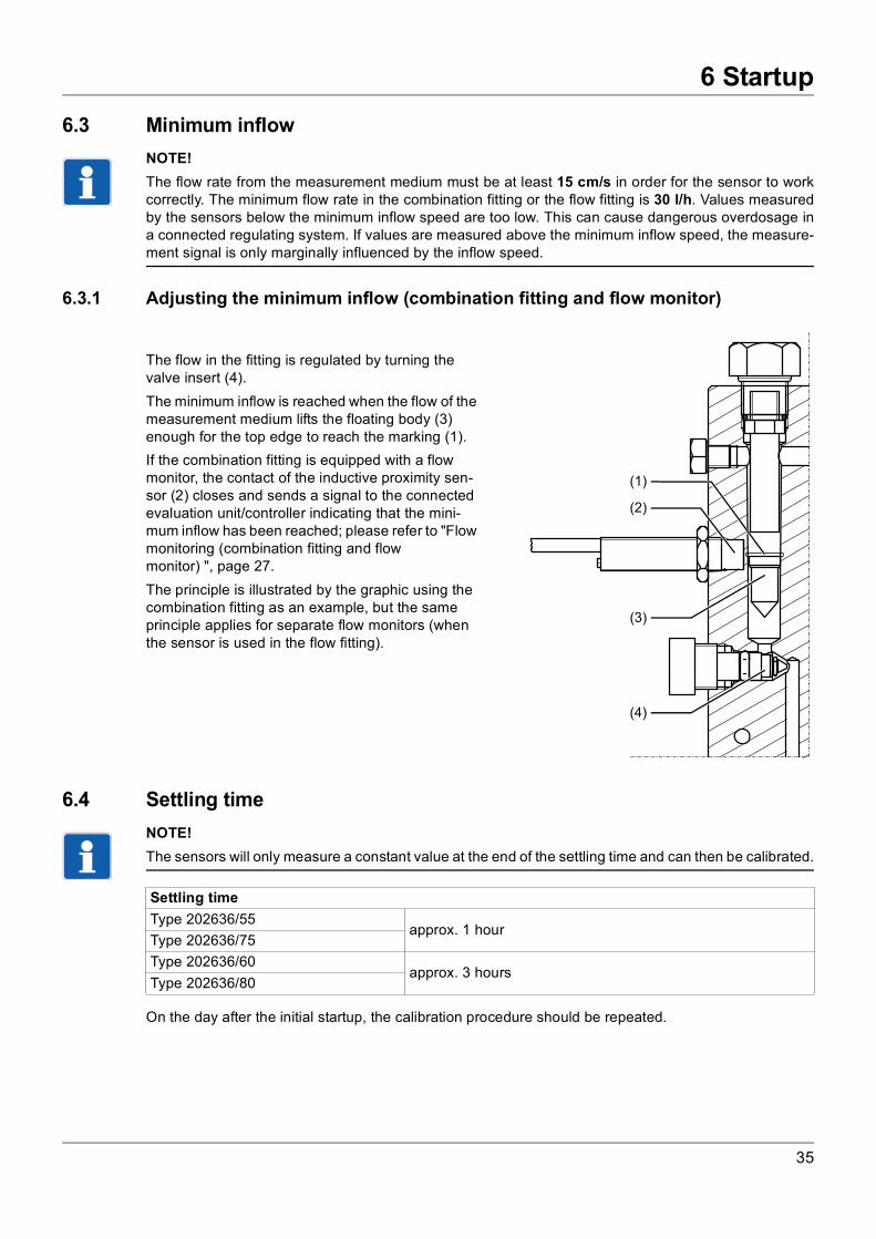
The flow in the fitting is regulated by turning the valve insert (4).The minimum inflow is reached when the flow of the measurement medium lifts the floating body (3) enough for the top edge to reach the marking (1).If the combination fitting is equipped with a flow monitor, the contact of the inductive proximity sen-sor (2) closes and sends a signal to the connected evaluation unit/controller indicating that the mini-mum inflow has been reached; please refer to "Flow monitoring (combination fitting and flow monitor) ", page 27.The principle is illustrated by the graphic using the combination fitting as an example, but the same principle applies for separate flow monitors (when the sensor is used in the flow fitting).
(1)
(2)
(3)
(4)
Settling timeType 202636/55
approx. 1 hourType 202636/75Type 202636/60
approx. 3 hoursType 202636/80
35
7 Maintenance
7 Maintenance
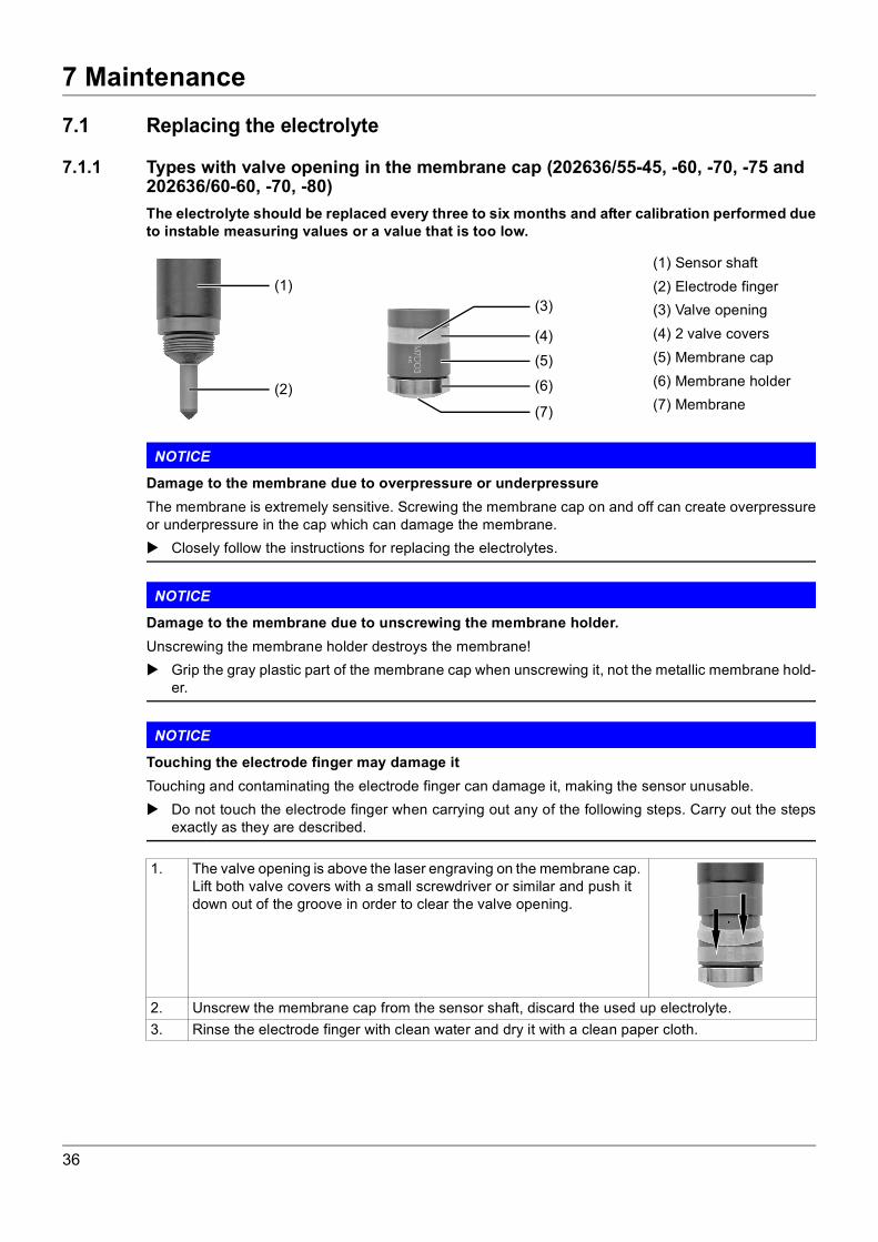
7.1 Replacing the electrolyte7.1.1 Types with valve opening in the membrane cap (202636/55-45, -60, -70, -75 and 202636/60-60, -70, -80)The electrolyte should be replaced every three to six months and after calibration performed dueto instable measuring values or a value that is too low.
NOTICE
Damage to the membrane due to overpressure or underpressureThe membrane is extremely sensitive. Screwing the membrane cap on and off can create overpressureor underpressure in the cap which can damage the membrane. Closely follow the instructions for replacing the electrolytes.
NOTICE
Damage to the membrane due to unscrewing the membrane holder.Unscrewing the membrane holder destroys the membrane! Grip the gray plastic part of the membrane cap when unscrewing it, not the metallic membrane hold-
er.
NOTICE
Touching the electrode finger may damage itTouching and contaminating the electrode finger can damage it, making the sensor unusable. Do not touch the electrode finger when carrying out any of the following steps. Carry out the steps
exactly as they are described.
(1) Sensor shaft(2) Electrode finger(3) Valve opening(4) 2 valve covers(5) Membrane cap(6) Membrane holder(7) Membrane
(1)
(2)
(3)
(4)
(5)
(7)
(6)
1. The valve opening is above the laser engraving on the membrane cap. Lift both valve covers with a small screwdriver or similar and push it down out of the groove in order to clear the valve opening.
2. Unscrew the membrane cap from the sensor shaft, discard the used up electrolyte.3. Rinse the electrode finger with clean water and dry it with a clean paper cloth.
36
7 Maintenance
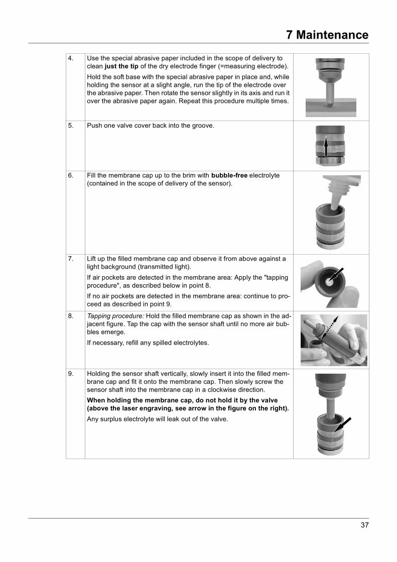
4. Use the special abrasive paper included in the scope of delivery toclean just the tip of the dry electrode finger (=measuring electrode).Hold the soft base with the special abrasive paper in place and, while holding the sensor at a slight angle, run the tip of the electrode over the abrasive paper. Then rotate the sensor slightly in its axis and run it over the abrasive paper again. Repeat this procedure multiple times.
5. Push one valve cover back into the groove.
6. Fill the membrane cap up to the brim with bubble-free electrolyte (contained in the scope of delivery of the sensor).
7. Lift up the filled membrane cap and observe it from above against a light background (transmitted light).If air pockets are detected in the membrane area: Apply the "tapping procedure", as described below in point 8.If no air pockets are detected in the membrane area: continue to pro-ceed as described in point 9.
8. Tapping procedure: Hold the filled membrane cap as shown in the ad-jacent figure. Tap the cap with the sensor shaft until no more air bub-bles emerge.If necessary, refill any spilled electrolytes.
9. Holding the sensor shaft vertically, slowly insert it into the filled mem-brane cap and fit it onto the membrane cap. Then slowly screw the sensor shaft into the membrane cap in a clockwise direction.When holding the membrane cap, do not hold it by the valve (above the laser engraving, see arrow in the figure on the right).Any surplus electrolyte will leak out of the valve.
37
7 Maintenance
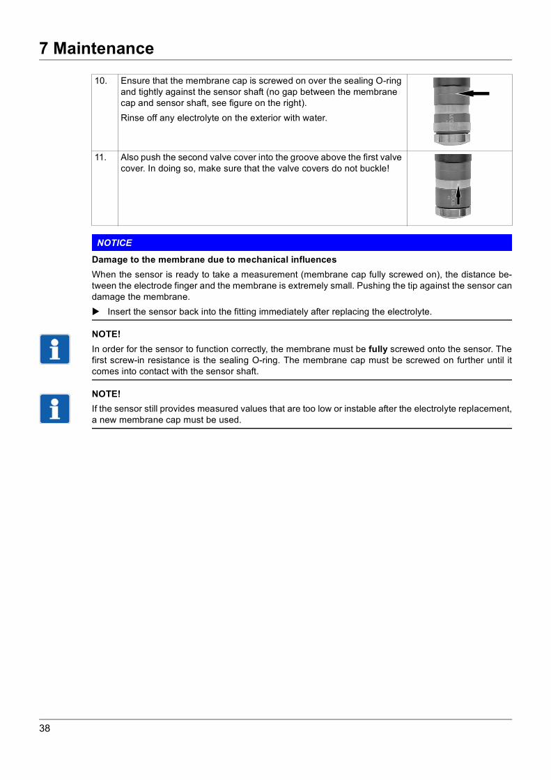
NOTICE
Damage to the membrane due to mechanical influencesWhen the sensor is ready to take a measurement (membrane cap fully screwed on), the distance be-tween the electrode finger and the membrane is extremely small. Pushing the tip against the sensor candamage the membrane. Insert the sensor back into the fitting immediately after replacing the electrolyte.
NOTE!In order for the sensor to function correctly, the membrane must be fully screwed onto the sensor. Thefirst screw-in resistance is the sealing O-ring. The membrane cap must be screwed on further until itcomes into contact with the sensor shaft.
NOTE!If the sensor still provides measured values that are too low or instable after the electrolyte replacement,a new membrane cap must be used.
10. Ensure that the membrane cap is screwed on over the sealing O-ring and tightly against the sensor shaft (no gap between the membrane cap and sensor shaft, see figure on the right).Rinse off any electrolyte on the exterior with water.
11. Also push the second valve cover into the groove above the first valve cover. In doing so, make sure that the valve covers do not buckle!
38

7 Maintenance
7.1.2 Types with an internal pressure compensation system (202636/55-81, /60-81, /60-85, /75 and /80)The electrolyte should be replaced every three to six months and after calibration performed dueto instable measuring values or a value that is too low.
NOTICE
Damage to the membrane due to unscrewing the membrane holder.Unscrewing the membrane holder destroys the membrane! Grip the gray plastic part of the membrane cap when unscrewing it, not the metallic membrane hold-
er.
NOTICE
Touching the electrode finger may damage itTouching and contaminating the electrode finger (2) can damage it, making the sensor unusable. Do not touch the electrode finger when carrying out any of the following steps. Carry out the steps
exactly as they are described.
(1) Sensor shaft(2) O-ring 20 × 1.5(3) Opening for
pressure compen-sation(4) Electrode finger(5) Membrane cap(6) Membrane holder(7) Membrane
(1)
(4)
(5)
(7)
(6)
(3)
(2)
1. Unscrew the membrane cap from the sensor shaft.2. Rinse the electrode finger with clean water and dry it with a clean paper cloth.3. Spin the sensor shaft downward several times with an outstretched arm (like when shaking a liq-
uid thermometer). This empties the opening for pressure compensation. Then dry it again using a clean paper towel.
4. Use the special abrasive paper included in the scope of delivery to clean just the tip of the dry electrode finger (=working electrode).To do so, hold the special abrasive paper in place by one corner, and, while holding the measuring cell vertically, run the tip of the electrode over the abrasive paper two or three times.
5. If the red O-ring 20 × 1.5 mm (2) is widened, it must be replaced.
39
7 Maintenance
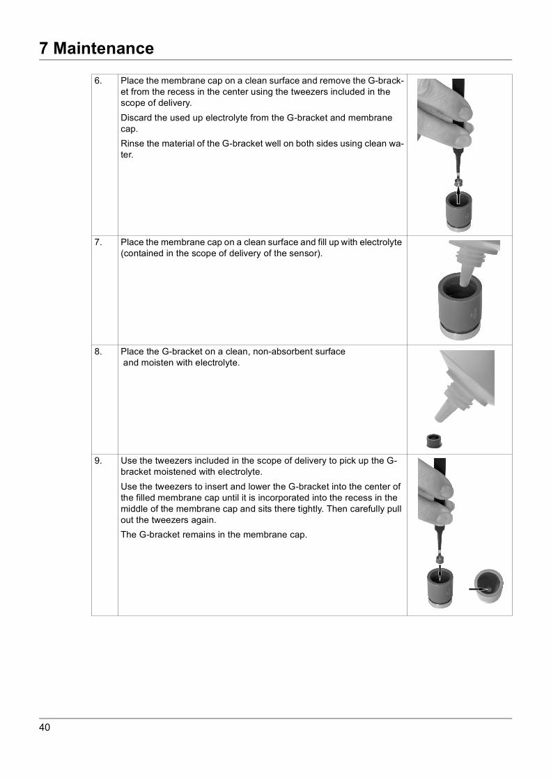
6. Place the membrane cap on a clean surface and remove the G-brack-et from the recess in the center using the tweezers included in the scope of delivery.Discard the used up electrolyte from the G-bracket and membrane cap.Rinse the material of the G-bracket well on both sides using clean wa-ter.
7. Place the membrane cap on a clean surface and fill up with electrolyte (contained in the scope of delivery of the sensor).
8. Place the G-bracket on a clean, non-absorbent surface and moisten with electrolyte.
9. Use the tweezers included in the scope of delivery to pick up the G-bracket moistened with electrolyte.Use the tweezers to insert and lower the G-bracket into the center of the filled membrane cap until it is incorporated into the recess in the middle of the membrane cap and sits there tightly. Then carefully pull out the tweezers again.The G-bracket remains in the membrane cap.
40
7 Maintenance
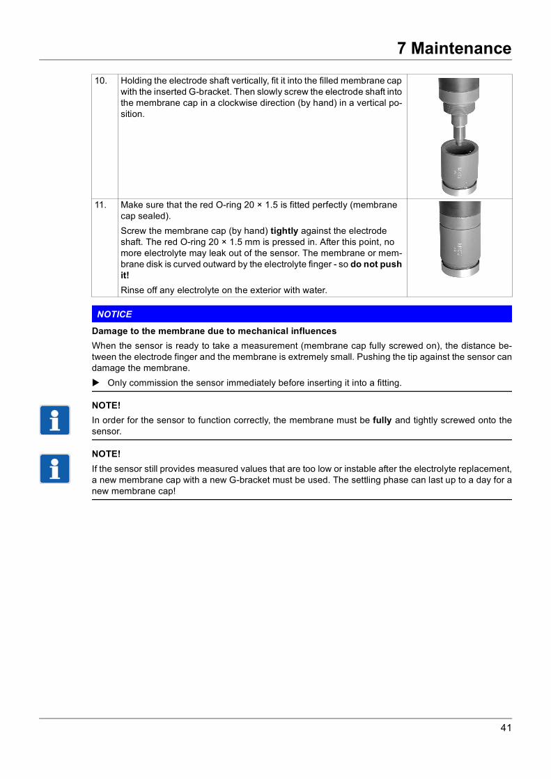
NOTICE
Damage to the membrane due to mechanical influencesWhen the sensor is ready to take a measurement (membrane cap fully screwed on), the distance be-tween the electrode finger and the membrane is extremely small. Pushing the tip against the sensor candamage the membrane. Only commission the sensor immediately before inserting it into a fitting.
NOTE!In order for the sensor to function correctly, the membrane must be fully and tightly screwed onto thesensor.
NOTE!If the sensor still provides measured values that are too low or instable after the electrolyte replacement,a new membrane cap with a new G-bracket must be used. The settling phase can last up to a day for anew membrane cap!
10. Holding the electrode shaft vertically, fit it into the filled membrane cap with the inserted G-bracket. Then slowly screw the electrode shaft into the membrane cap in a clockwise direction (by hand) in a vertical po-sition.
11. Make sure that the red O-ring 20 × 1.5 is fitted perfectly (membrane cap sealed).Screw the membrane cap (by hand) tightly against the electrode shaft. The red O-ring 20 × 1.5 mm is pressed in. After this point, no more electrolyte may leak out of the sensor. The membrane or mem-brane disk is curved outward by the electrolyte finger - so do not push it!Rinse off any electrolyte on the exterior with water.
41

7 Maintenance
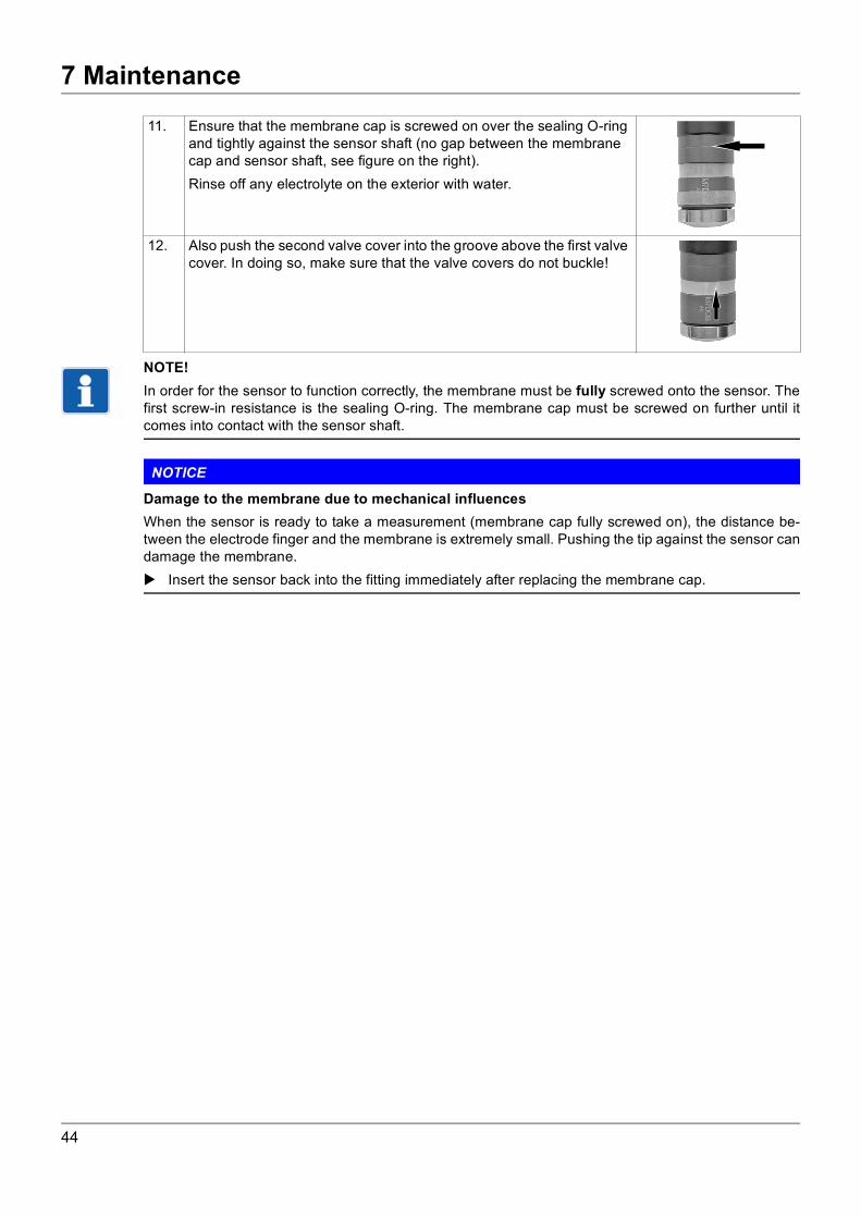
7.2 Replacing the membrane cap7.2.1 Types with valve opening in the membrane cap (202636/55-45, -60, -70, -75 and 202636/60-60, -70, -80)The membrane cap should be renewed under the following conditions:• regularly after one year of operation• if the measured values are still too low or instable after a prior calibration
NOTICE
Damage to the membrane due to overpressure or underpressureThe membrane is extremely sensitive. Screwing the membrane cap on and off can create overpressureor underpressure in the cap which can damage the membrane. Closely follow the instructions for replacing the membrane cap.
NOTICE
Touching the electrode finger may damage itTouching and contaminating the electrode finger can damage it, making the sensor unusable. Do not touch the electrode finger when carrying out any of the following steps. Carry out the steps
exactly as they are described.
NOTE!The membrane cap is supplied in a can filled with liquid (water) so that an air layer cannot form on theinside of the membrane.
(1) Sensor shaft(2) Electrode finger(3) Valve opening(4) 2 valve covers(5) Membrane cap(6) Membrane holder(7) Membrane
(1)
(2)
(3)
(4)
(5)
(7)
(6)
1. The valve opening is above the laser engraving on the membrane cap. Lift both valve covers with a small screwdriver or similar and push it down out of the groove in order to clear the valve opening.
2. Unscrew the membrane cap from the sensor shaft, discard the used up electrolyte.3. Rinse the electrode finger with clean water and dry it with a clean paper cloth.4. Open the can with the new membrane cap, and drain the liquid (water) from the can.
42
7 Maintenance
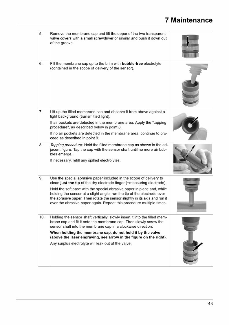
5. Remove the membrane cap and lift the upper of the two transparentvalve covers with a small screwdriver or similar and push it down out of the groove.
6. Fill the membrane cap up to the brim with bubble-free electrolyte (contained in the scope of delivery of the sensor).
7. Lift up the filled membrane cap and observe it from above against a light background (transmitted light).If air pockets are detected in the membrane area: Apply the "tapping procedure", as described below in point 8.If no air pockets are detected in the membrane area: continue to pro-ceed as described in point 9.
8. Tapping procedure: Hold the filled membrane cap as shown in the ad-jacent figure. Tap the cap with the sensor shaft until no more air bub-bles emerge.If necessary, refill any spilled electrolytes.
9. Use the special abrasive paper included in the scope of delivery to clean just the tip of the dry electrode finger (=measuring electrode).Hold the soft base with the special abrasive paper in place and, while holding the sensor at a slight angle, run the tip of the electrode over the abrasive paper. Then rotate the sensor slightly in its axis and run it over the abrasive paper again. Repeat this procedure multiple times.
10. Holding the sensor shaft vertically, slowly insert it into the filled mem-brane cap and fit it onto the membrane cap. Then slowly screw the sensor shaft into the membrane cap in a clockwise direction.When holding the membrane cap, do not hold it by the valve (above the laser engraving, see arrow in the figure on the right).Any surplus electrolyte will leak out of the valve.
43
7 Maintenance
NOTE!In order for the sensor to function correctly, the membrane must be fully screwed onto the sensor. Thefirst screw-in resistance is the sealing O-ring. The membrane cap must be screwed on further until itcomes into contact with the sensor shaft.
NOTICE
Damage to the membrane due to mechanical influencesWhen the sensor is ready to take a measurement (membrane cap fully screwed on), the distance be-tween the electrode finger and the membrane is extremely small. Pushing the tip against the sensor candamage the membrane. Insert the sensor back into the fitting immediately after replacing the membrane cap.
11. Ensure that the membrane cap is screwed on over the sealing O-ring and tightly against the sensor shaft (no gap between the membrane cap and sensor shaft, see figure on the right).Rinse off any electrolyte on the exterior with water.
12. Also push the second valve cover into the groove above the first valve cover. In doing so, make sure that the valve covers do not buckle!
44
7 Maintenance
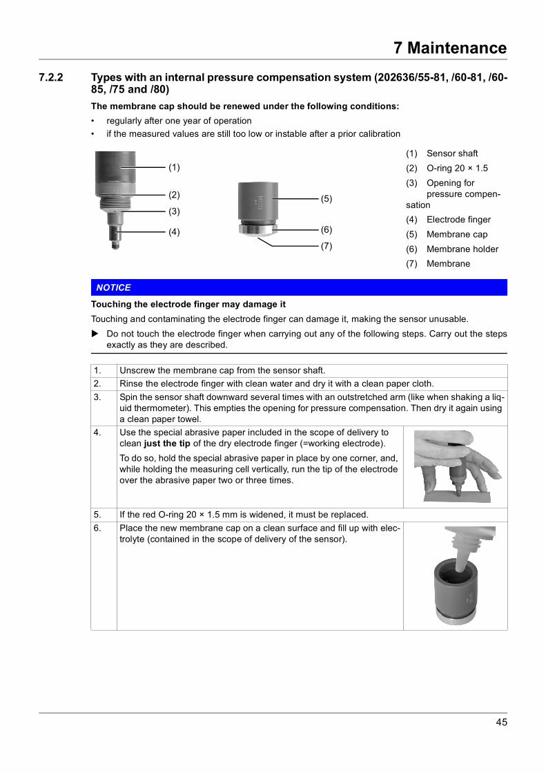
7.2.2 Types with an internal pressure compensation system (202636/55-81, /60-81, /60-85, /75 and /80)The membrane cap should be renewed under the following conditions:• regularly after one year of operation• if the measured values are still too low or instable after a prior calibration
NOTICE
Touching the electrode finger may damage itTouching and contaminating the electrode finger can damage it, making the sensor unusable. Do not touch the electrode finger when carrying out any of the following steps. Carry out the steps
exactly as they are described.
(1) Sensor shaft(2) O-ring 20 × 1.5(3) Opening for
pressure compen-sation(4) Electrode finger(5) Membrane cap(6) Membrane holder(7) Membrane
(1)
(4)
(5)
(7)
(6)
(3)
(2)
1. Unscrew the membrane cap from the sensor shaft.2. Rinse the electrode finger with clean water and dry it with a clean paper cloth.3. Spin the sensor shaft downward several times with an outstretched arm (like when shaking a liq-
uid thermometer). This empties the opening for pressure compensation. Then dry it again using a clean paper towel.
4. Use the special abrasive paper included in the scope of delivery to clean just the tip of the dry electrode finger (=working electrode).To do so, hold the special abrasive paper in place by one corner, and, while holding the measuring cell vertically, run the tip of the electrode over the abrasive paper two or three times.
5. If the red O-ring 20 × 1.5 mm is widened, it must be replaced.6. Place the new membrane cap on a clean surface and fill up with elec-
trolyte (contained in the scope of delivery of the sensor).
45
7 Maintenance
NOTICE
Damage to the membrane due to mechanical influencesWhen the sensor is ready to take a measurement (membrane cap fully screwed on), the distance be-tween the electrode finger and the membrane is extremely small. Pushing the tip against the sensor candamage the membrane. Only commission the sensor immediately before inserting it into a fitting.
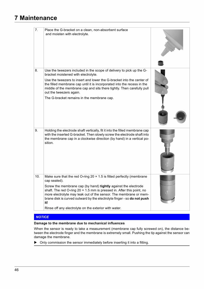
7. Place the G-bracket on a clean, non-absorbent surface and moisten with electrolyte.
8. Use the tweezers included in the scope of delivery to pick up the G-bracket moistened with electrolyte.Use the tweezers to insert and lower the G-bracket into the center of the filled membrane cap until it is incorporated into the recess in the middle of the membrane cap and sits there tightly. Then carefully pull out the tweezers again.The G-bracket remains in the membrane cap.
9. Holding the electrode shaft vertically, fit it into the filled membrane cap with the inserted G-bracket. Then slowly screw the electrode shaft into the membrane cap in a clockwise direction (by hand) in a vertical po-sition.
10. Make sure that the red O-ring 20 × 1.5 is fitted perfectly (membrane cap sealed).Screw the membrane cap (by hand) tightly against the electrode shaft. The red O-ring 20 × 1.5 mm is pressed in. After this point, no more electrolyte may leak out of the sensor. The membrane or mem-brane disk is curved outward by the electrolyte finger - so do not push it!Rinse off any electrolyte on the exterior with water.
46
7 Maintenance
NOTE!In order for the sensor to function correctly, the membrane must be fully and tightly screwed onto thesensor.NOTE!The settling phase can last up to a day for a new membrane cap! If the sensor still provides measuredvalues that are too low or instable after the membrane cap replacement, the manufacturer must performa check/overhaul.
47

7 Maintenance
7.3 StorageNOTE!Membrane caps which have been in operation for longer than a day cannot be stored and used again.
7.3.1 Types with valve opening in the membrane cap (202636/55-45, -60, -70, -75 and 202636/60-60, -70, -80)
NOTICE
Damage to the membrane due to overpressure or underpressureThe membrane is extremely sensitive. Screwing the membrane cap on and off can create overpressureor underpressure in the cap which can damage the membrane. Closely follow the instructions for unscrewing and screwing the membrane cap
(chapter 6.1 "Important notes for screwing the membrane cap on and off", page 29).
Preparation for storage
1. Open valve cover(s) of the membrane cap.
2. Unscrew the membrane cap from the sensor shaft.
3. Discard the electrolyte.
4. Rinse the membrane cap and electrode finger with tap water and dry them, ensuring they are freefrom dust.
5. Loosely screw the dry membrane cap onto the sensor shaft. The membrane must not be positionedat the tip of the electrode finger.
The sensor is ready to be stored.
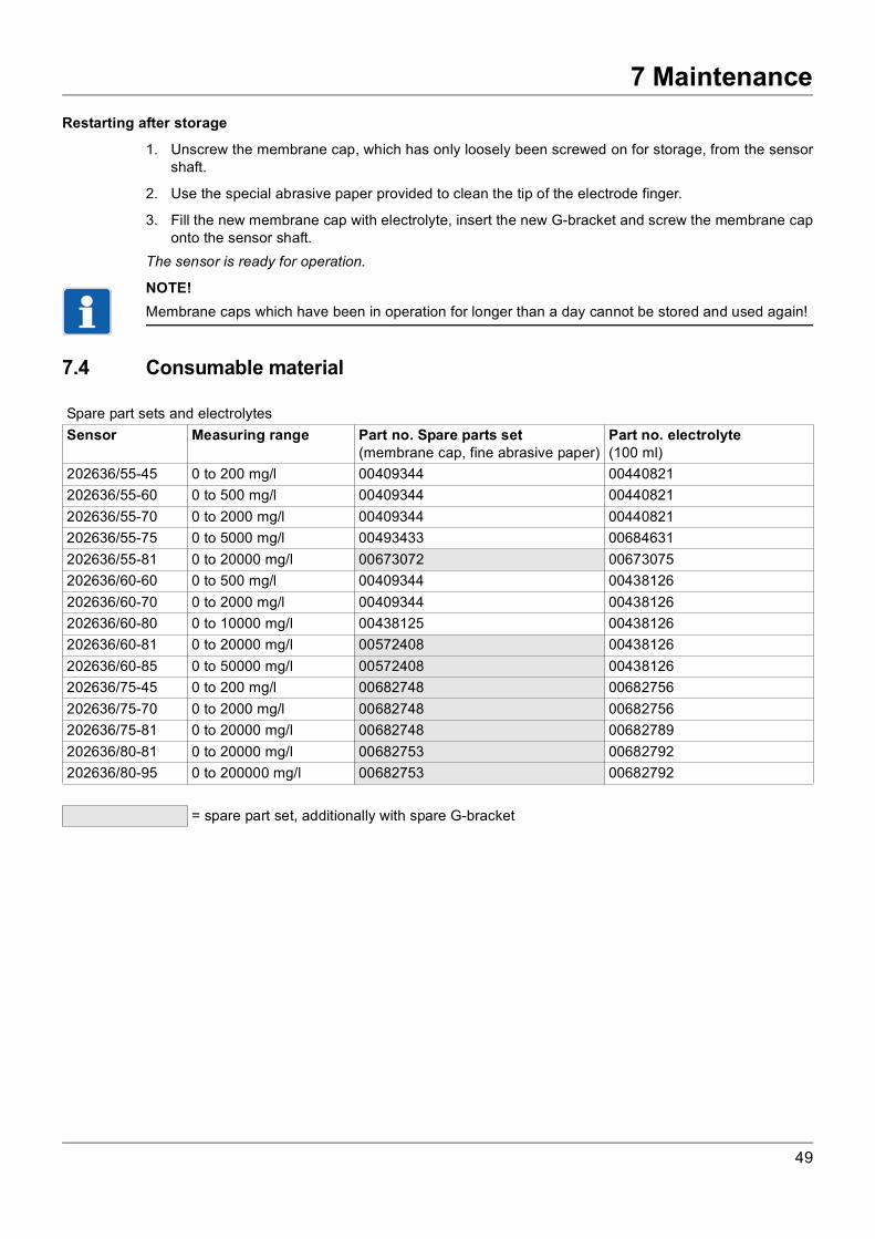
Restarting after storage
1. Unscrew the membrane cap, which has only loosely been screwed on for storage, from the sensorshaft.
2. Use the special abrasive paper provided to clean the tip of the electrode finger.
3. Fill the new membrane cap with electrolyte and screw it onto the sensor shaft.Make sure that the valve opening is not held shut.
The sensor is ready for operation.
7.3.2 Types with an internal pressure compensation system (202636/55-81, /60-81, /60-85, /75 and /80)
Preparation for storage
1. Unscrew the membrane cap from the sensor shaft.
2. Remove the G-bracket from the membrane cap using the tweezers provided.
3. Discard the electrolyte.
4. Rinse the membrane cap and electrode finger with distilled water and dry them, ensuring they arefree from dust.
5. Loosely screw the dry membrane cap onto the sensor shaft. The membrane must not be positionedat the tip of the electrode finger.
The sensor is ready to be stored.
48
7 Maintenance
Restarting after storage1. Unscrew the membrane cap, which has only loosely been screwed on for storage, from the sensorshaft.
2. Use the special abrasive paper provided to clean the tip of the electrode finger.
3. Fill the new membrane cap with electrolyte, insert the new G-bracket and screw the membrane caponto the sensor shaft.
The sensor is ready for operation.
NOTE!Membrane caps which have been in operation for longer than a day cannot be stored and used again!
7.4 Consumable material
Spare part sets and electrolytesSensor Measuring range Part no. Spare parts set
(membrane cap, fine abrasive paper)Part no. electrolyte(100 ml)
202636/55-45 0 to 200 mg/l 00409344 00440821202636/55-60 0 to 500 mg/l 00409344 00440821202636/55-70 0 to 2000 mg/l 00409344 00440821202636/55-75 0 to 5000 mg/l 00493433 00684631202636/55-81 0 to 20000 mg/l 00673072 00673075202636/60-60 0 to 500 mg/l 00409344 00438126202636/60-70 0 to 2000 mg/l 00409344 00438126202636/60-80 0 to 10000 mg/l 00438125 00438126202636/60-81 0 to 20000 mg/l 00572408 00438126202636/60-85 0 to 50000 mg/l 00572408 00438126202636/75-45 0 to 200 mg/l 00682748 00682756202636/75-70 0 to 2000 mg/l 00682748 00682756202636/75-81 0 to 20000 mg/l 00682748 00682789202636/80-81 0 to 20000 mg/l 00682753 00682792202636/80-95 0 to 200000 mg/l 00682753 00682792
= spare part set, additionally with spare G-bracket
49

8 Calibration
8 Calibration
8.1 General informationNOTE!According to requirements, the sensor should be inspected or calibrated at regular fixed intervals.Recommendation: weekly, or more frequently depending on the accuracy requirements.
8.2 Calibrating with an indicator/controllerReference method
NOTE!The single-stage sulphuric acid titration with potassium permanganate and sodium thiosulfate is a suit-able reference method for calibrating the sensors for hydrogen peroxide (202636/60 and /80).The two-stage sulphuric acid titration with potassium permanganate and sodium thiosulfate is a suitablereference method for calibrating the sensors for peracetic acid (202636/55 and /75).
You can find more information on this in chapter 11.1 "Suitable titration methods", page 58.
Initial situation• Display format and measuring range are set, refer to the operating manual for the indicator/controller
used.• The sensor is installed in a suitable flow fitting (refer to chapter 4.3 "Flow fitting for membrane-cov-
ered sensors (type 202811/30)", page 22) or combination fitting (refer to chapter 4.2 "Combinationfitting (type 202811/10)", page 19).
• The settling time for the sensor (1 hour for types 202636/55 and /75; 3 hours for types 202636/60and /80) has elapsed and the measured value is stable.
Procedure
1. Take a water sample from the outlet of the fitting (or from the immediate vicinity).
2. Immediately determine the analyte concentration (hydrogen peroxide or peracetic acid) of the sam-ple using a suitable reference method.
3. Calibrate the indicator on the basis of the reference value; refer to the operating manual for the trans-mitter/controller used.
Checking the determined slopeMany transmitters/controllers (e.g. the JUMO AQUIS 500 AS) have a "calibration logbook". This logbookis used to record the relevant data during every calibration.
NOTE!If the value for the nominal slope is under 30%, the membrane cap and the electrolyte must be replacedand the electrode tip must be cleaned; see chapter 7.2 "Replacing the membrane cap", page 42.
Setting the slope manuallyRefer to the operating manual for the transmitter/controller used.
Zero point adjustmentA zero point adjustment is not required for the sensors described in this operating manual. If there is noanalyte in the measurement medium, the value displayed will be a zero. The zero point is not dependenton changes in the flow, conductivity, temperature or the pH value.
50

9 Overcoming errors and malfunctions
9 Overcoming errors and malfunctions
9.1 General troubleshootingError/fault Possible cause Remedy Preventative measuresOutput signal of the sensor is too low or too high
Incorrect calibration Repeat calibration accord-ing to the titration method; refer to chapter 8.2 "Calibrating with an indicator/controller", page 50
Calibrate the sensor more fre-quently, if required
Output signal of the sensor is too lowSensor cannot be calibrat-ed to the titration value
Settling time too short Wait for at least two hoursDeposit on the electrode finger tip (measuring electrode)
Clean the electrode finger tip
Shorten the maintenance inter-vals, if required
Inflow to the measuring cell is too low
Increase the inflow Monitor the minimum inflow
Output signal of the sensor is too lowSensor cannot be calibrat-ed to the titration valueOutput signal of the sensor decreases or stays the same when the titration val-ue is increasedFluctuating signal
Membrane destroyed:electrolyte leaking out - measurement medium leaking in
Replace the membrane cap Avoid damaging the mem-brane. Do not push the sensor open when the membrane cap is screwed on. Prevent coarse particles or fragments of glass from flowing in
Deposits on themembrane cap
Replace the membrane cap
Gas bubbles on the out-side of the membrane
Briefly increase the flow Check the installation and change if necessary
No electrolyte in the membrane cap
Fill the membrane cap with electrolyte; refer to chapter 7.1 "Replacing the electrolyte", page 36
Output signal of the sensor is too high. Sensor cannot be calibrated to the titration value
Besides the analytes, the measurement medi-um also contains other oxidizing agents, such as Cl2
Avoid adding these sub-stances. Change the water
Ensure cleaning agents and disinfectants are removed fully after use
The titration and sensor val-ues match; the redox mea-surement trend is correct, but the setpoint value is not reached
Incorrect control param-eters
Optimize the control param-eters
The amount of disinfec-tant dosed per unit of time is too high. The concentration is exceed-ed before the measure-ment medium reaches the sensor
Reduce the amount ad-mixed per unit of time. Re-duce the concentration of disinfectant in the solution added
Flow through the system is too low
Improve through-mixing Implement structural mea-sures for better through-mixing
Sensor and titration values do not match; the sensor values fluctuate: too high/too low
Incorrect control param-eters
Optimize the control param-eters
Flow through the system is too low
Improve through-mixing Implement structural mea-sures for better through-mixing
51
9 Overcoming errors and malfunctions
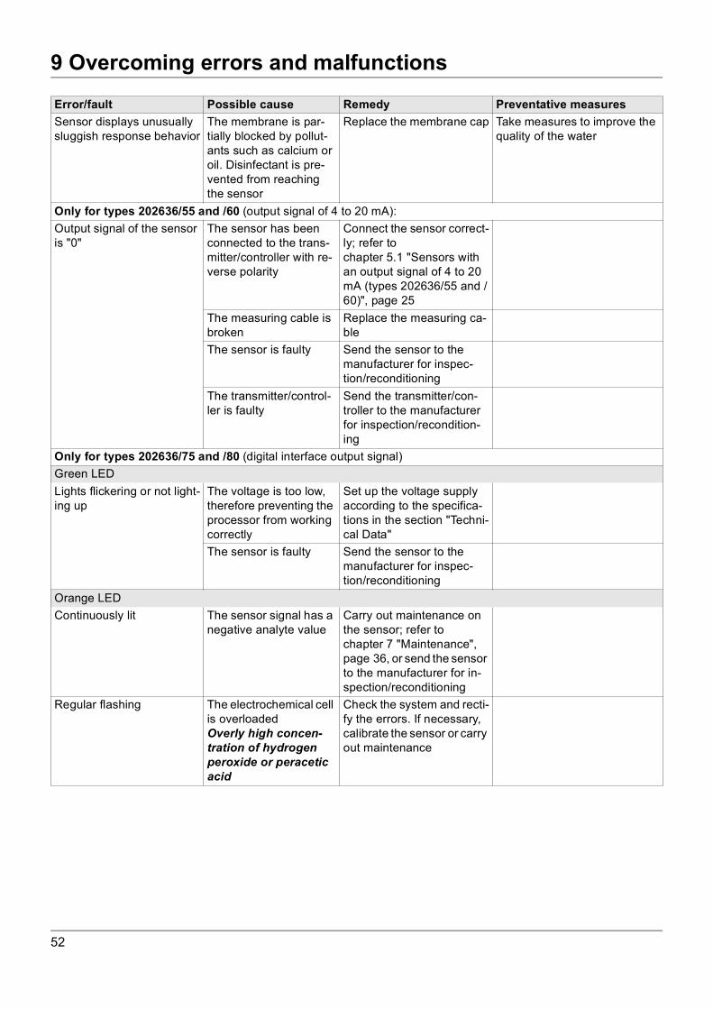
Sensor displays unusually sluggish response behavior
The membrane is par-tially blocked by pollut-ants such as calcium or oil. Disinfectant is pre-vented from reaching the sensor
Replace the membrane cap Take measures to improve the quality of the water
Only for types 202636/55 and /60 (output signal of 4 to 20 mA):Output signal of the sensor is "0"
The sensor has been connected to the trans-mitter/controller with re-verse polarity
Connect the sensor correct-ly; refer to chapter 5.1 "Sensors with an output signal of 4 to 20 mA (types 202636/55 and /60)", page 25
The measuring cable is broken
Replace the measuring ca-ble
The sensor is faulty Send the sensor to the manufacturer for inspec-tion/reconditioning
The transmitter/control-ler is faulty
Send the transmitter/con-troller to the manufacturer for inspection/recondition-ing
Only for types 202636/75 and /80 (digital interface output signal)Green LEDLights flickering or not light-ing up
The voltage is too low, therefore preventing the processor from working correctly
Set up the voltage supply according to the specifica-tions in the section "Techni-cal Data"
The sensor is faulty Send the sensor to the manufacturer for inspec-tion/reconditioning
Orange LEDContinuously lit The sensor signal has a
negative analyte valueCarry out maintenance on the sensor; refer to chapter 7 "Maintenance", page 36, or send the sensor to the manufacturer for in-spection/reconditioning
Regular flashing The electrochemical cell is overloadedOverly high concen-tration of hydrogen peroxide or peracetic acid
Check the system and recti-fy the errors. If necessary, calibrate the sensor or carry out maintenance
Error/fault Possible cause Remedy Preventative measures
52
9 Overcoming errors and malfunctions
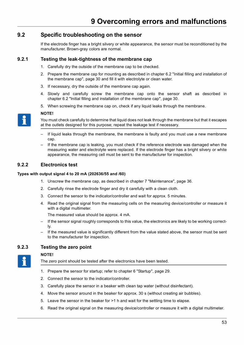
9.2 Specific troubleshooting on the sensorIf the electrode finger has a bright silvery or white appearance, the sensor must be reconditioned by themanufacturer. Brown-gray colors are normal.
9.2.1 Testing the leak-tightness of the membrane cap1. Carefully dry the outside of the membrane cap to be checked.
2. Prepare the membrane cap for mounting as described in chapter 6.2 "Initial filling and installation ofthe membrane cap", page 30 and fill it with electrolyte or clean water.
3. If necessary, dry the outside of the membrane cap again.
4. Slowly and carefully screw the membrane cap onto the sensor shaft as described inchapter 6.2 "Initial filling and installation of the membrane cap", page 30.
5. When screwing the membrane cap on, check if any liquid leaks through the membrane.
NOTE!You must check carefully to determine that liquid does not leak through the membrane but that it escapesat the outlets designed for this purpose; repeat the leakage test if necessary.
– If liquid leaks through the membrane, the membrane is faulty and you must use a new membranecap.
– If the membrane cap is leaking, you must check if the reference electrode was damaged when themeasuring water and electrolyte were replaced. If the electrode finger has a bright silvery or whiteappearance, the measuring cell must be sent to the manufacturer for inspection.
9.2.2 Electronics test
Types with output signal 4 to 20 mA (202636/55 and /60)
1. Unscrew the membrane cap, as described in chapter 7 "Maintenance", page 36.
2. Carefully rinse the electrode finger and dry it carefully with a clean cloth.
3. Connect the sensor to the indicator/controller and wait for approx. 5 minutes.
4. Read the original signal from the measuring cells on the measuring device/controller or measure itwith a digital multimeter.The measured value should be approx. 4 mA.
– If the sensor signal roughly corresponds to this value, the electronics are likely to be working correct-ly.
– If the measured value is significantly different from the value stated above, the sensor must be sentto the manufacturer for inspection.
9.2.3 Testing the zero pointNOTE!The zero point should be tested after the electronics have been tested.
1. Prepare the sensor for startup; refer to chapter 6 "Startup", page 29.
2. Connect the sensor to the indicator/controller.
3. Carefully place the sensor in a beaker with clean tap water (without disinfectant).
4. Move the sensor around in the beaker for approx. 30 s (without creating air bubbles).
5. Leave the sensor in the beaker for >1 h and wait for the settling time to elapse.
6. Read the original signal on the measuring device/controller or measure it with a digital multimeter.
53

9 Overcoming errors and malfunctions
7. The sensor signal should be around the zero point.– If the sensor signal tends towards zero, the zero point is very likely to be okay.– If the measured value deviates significantly from zero, maintenance must be carried out on the sen-
sor (refer to chapter 7 "Maintenance", page 36) and the "zero point test" must be repeated. Note thata recently cleaned working electrode (measuring electrode) has a relatively high zero point. In thiscase, the sensor will take a few days to reach its lowest zero point.
– If the measured value does not tend towards zero, even after maintenance has been carried out, thesensor must be sent to the manufacturer for inspection.
NOTE!In general, the zero points of sensors with an extremely small measuring range, or which are more sen-sitive, are slightly higher than for sensors with large measuring ranges or which are less sensitive.
9.2.4 Measurement signal testNOTE!The signal should be tested after the zero point has been tested.
1. Add a little disinfectant to the water in the beaker (which was used in the section "Testing the zeropoint"; refer to chapter 9.2.3 "Testing the zero point", page 53).
2. With the sensor connected to the measuring device, move it around as evenly as possible in the bea-ker for at least five minutes.
3. Check to see if the measuring signal increases in this time.
– If the sensor signal increases, the sensor is likely to be working correctly. If the sensor does not reactto the disinfectant, carry out maintenance on the sensor (refer to chapter 7 "Maintenance", page 36)before repeating the "signal test".
– If the sensor still does not react to the disinfectant after these steps have been carried out, it mustbe sent to the manufacturer for inspection.
9.2.5 Testing the environmentIf the cause of the error cannot be clearly identified after carrying out the tests mentioned above, the fol-lowing points in the area around the measuring chain must be tested:
■ Flow ■ Measuring cable■ Indicating device / controller ■ pH value of the measured water■ Dosing device ■ Temperature of the measured water■ Correct calibration ■ Analysis■ Pressure in the flow fitting ■ Suitability of the sensor for measuring the dosed
disinfectant■ Concentration of the disinfectant in the mea-
sured water (analysis)■ Concentration of the disinfectant in the dosing
tank
54
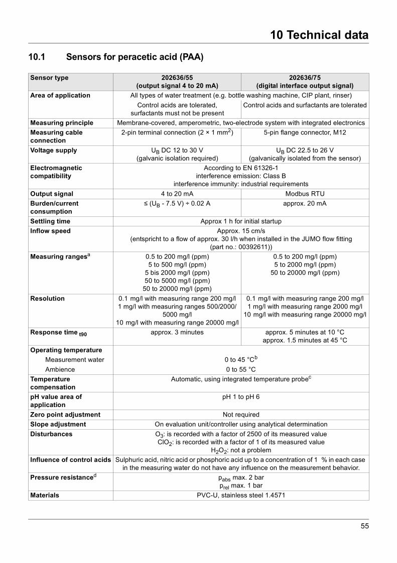
10 Technical data
10 Technical data
10.1 Sensors for peracetic acid (PAA)Sensor type 202636/55(output signal 4 to 20 mA)
202636/75(digital interface output signal)
Area of application All types of water treatment (e.g. bottle washing machine, CIP plant, rinser)Control acids are tolerated,
surfactants must not be presentControl acids and surfactants are tolerated
Measuring principle Membrane-covered, amperometric, two-electrode system with integrated electronicsMeasuring cableconnection
2-pin terminal connection (2 × 1 mm2) 5-pin flange connector, M12
Voltage supply UB DC 12 to 30 V(galvanic isolation required)
UB DC 22.5 to 26 V(galvanically isolated from the sensor)
Electromagneticcompatibility
According to EN 61326-1interference emission: Class B
interference immunity: industrial requirementsOutput signal 4 to 20 mA Modbus RTUBurden/currentconsumption
≤ (UB - 7.5 V) ÷ 0.02 A approx. 20 mA
Settling time Approx 1 h for initial startupInflow speed Approx. 15 cm/s
(entspricht to a flow of approx. 30 l/h when installed in the JUMO flow fitting(part no.: 00392611))
Measuring rangesa 0.5 to 200 mg/l (ppm)5 to 500 mg/l (ppm)
5 bis 2000 mg/l (ppm)50 to 5000 mg/l (ppm)
50 to 20000 mg/l (ppm)
0.5 to 200 mg/l (ppm)5 to 2000 mg/l (ppm)
50 to 20000 mg/l (ppm)
Resolution 0.1 mg/l with measuring range 200 mg/l1 mg/l with measuring ranges 500/2000/
5000 mg/l10 mg/l with measuring range 20000 mg/l
0.1 mg/l with measuring range 200 mg/l1 mg/l with measuring range 2000 mg/l
10 mg/l with measuring range 20000 mg/l
Response time t90 approx. 3 minutes approx. 5 minutes at 10 °Capprox. 1.5 minutes at 45 °C
Operating temperatureMeasurement water 0 to 45 °Cb
Ambience 0 to 55 °CTemperaturecompensation
Automatic, using integrated temperature probec
pH value area ofapplication
pH 1 to pH 6
Zero point adjustment Not requiredSlope adjustment On evaluation unit/controller using analytical determinationDisturbances O3: is recorded with a factor of 2500 of its measured value
ClO2: is recorded with a factor of 1 of its measured valueH2O2: not a problem
Influence of control acids Sulphuric acid, nitric acid or phosphoric acid up to a concentration of 1 % in each case in the measuring water do not have any influence on the measurement behavior.
Pressure resistanced pabs max. 2 barprel max. 1 bar
Materials PVC-U, stainless steel 1.4571
55
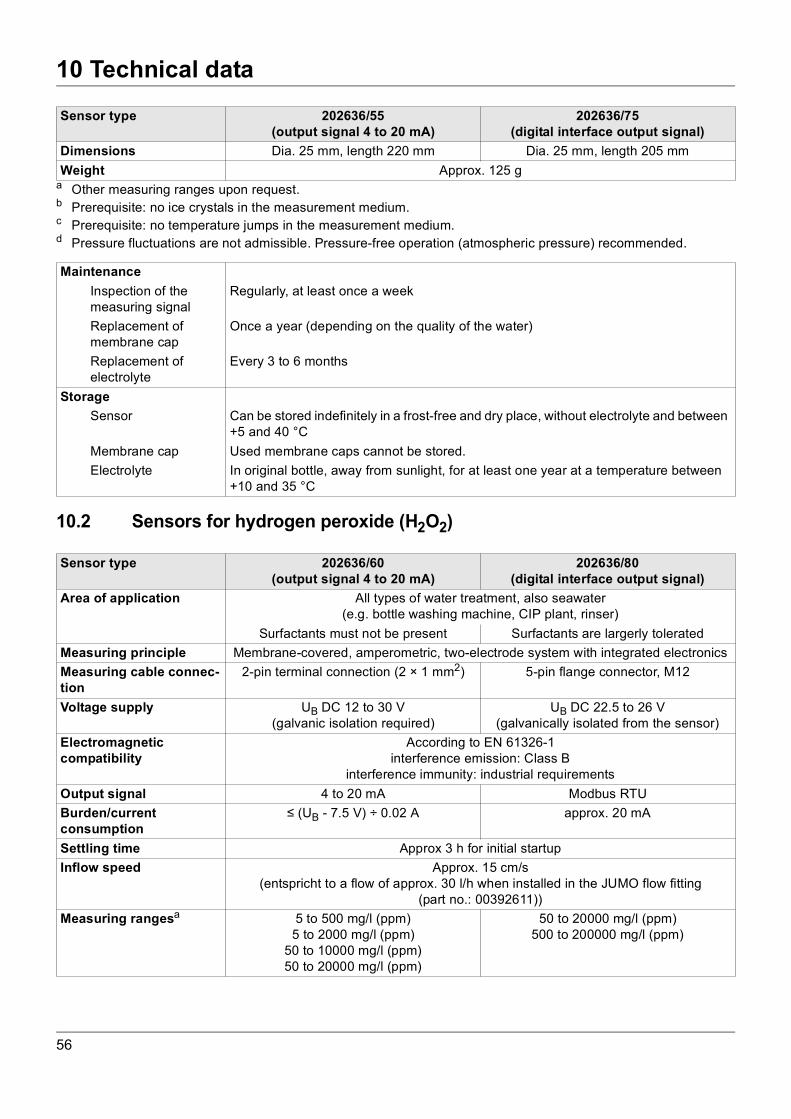
10 Technical data
10.2 Sensors for hydrogen peroxide (H2O2)
Dimensions Dia. 25 mm, length 220 mm Dia. 25 mm, length 205 mmWeight Approx. 125 g
a Other measuring ranges upon request.b Prerequisite: no ice crystals in the measurement medium.c Prerequisite: no temperature jumps in the measurement medium.d Pressure fluctuations are not admissible. Pressure-free operation (atmospheric pressure) recommended.
Sensor type 202636/55(output signal 4 to 20 mA)
202636/75(digital interface output signal)
MaintenanceInspection of themeasuring signal
Regularly, at least once a week
Replacement ofmembrane cap
Once a year (depending on the quality of the water)
Replacement ofelectrolyte
Every 3 to 6 months
StorageSensor Can be stored indefinitely in a frost-free and dry place, without electrolyte and between
+5 and 40 °CMembrane cap Used membrane caps cannot be stored.Electrolyte In original bottle, away from sunlight, for at least one year at a temperature between
+10 and 35 °C
Sensor type 202636/60(output signal 4 to 20 mA)
202636/80(digital interface output signal)
Area of application All types of water treatment, also seawater(e.g. bottle washing machine, CIP plant, rinser)
Surfactants must not be present Surfactants are largerly toleratedMeasuring principle Membrane-covered, amperometric, two-electrode system with integrated electronicsMeasuring cable connec-tion
2-pin terminal connection (2 × 1 mm2) 5-pin flange connector, M12
Voltage supply UB DC 12 to 30 V(galvanic isolation required)
UB DC 22.5 to 26 V(galvanically isolated from the sensor)
Electromagneticcompatibility
According to EN 61326-1interference emission: Class B
interference immunity: industrial requirementsOutput signal 4 to 20 mA Modbus RTUBurden/currentconsumption
≤ (UB - 7.5 V) ÷ 0.02 A approx. 20 mA
Settling time Approx 3 h for initial startupInflow speed Approx. 15 cm/s
(entspricht to a flow of approx. 30 l/h when installed in the JUMO flow fitting(part no.: 00392611))
Measuring rangesa 5 to 500 mg/l (ppm)5 to 2000 mg/l (ppm)
50 to 10000 mg/l (ppm)50 to 20000 mg/l (ppm)
50 to 20000 mg/l (ppm)500 to 200000 mg/l (ppm)
56
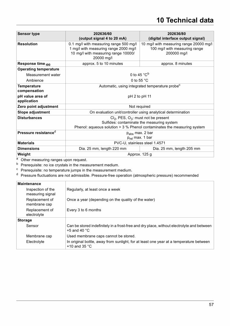
10 Technical data
Resolution 0.1 mg/l with measuring range 500 mg/l1 mg/l with measuring range 2000 mg/l10 mg/l with measuring range 10000/
20000 mg/l
10 mg/l with measuring range 20000 mg/l100 mg/l with measuring range
200000 mg/l
Response time t90 approx. 5 to 10 minutes approx. 8 minutesOperating temperature
Measurement water 0 to 45 °Cb
Ambience 0 to 55 °CTemperaturecompensation
Automatic, using integrated temperature probec
pH value area ofapplication
pH 2 to pH 11
Zero point adjustment Not requiredSlope adjustment On evaluation unit/controller using analytical determinationDisturbances Cl2, PES, O3: must not be present
Sulfides: contaminate the measuring systemPhenol: aqueous solution > 3 % Phenol contaminates the measuring system
Pressure resistanced pabs max. 2 barprel max. 1 bar
Materials PVC-U, stainless steel 1.4571Dimensions Dia. 25 mm, length 220 mm Dia. 25 mm, length 205 mmWeight Approx. 125 g
a Other measuring ranges upon request.b Prerequisite: no ice crystals in the measurement medium.c Prerequisite: no temperature jumps in the measurement medium.d Pressure fluctuations are not admissible. Pressure-free operation (atmospheric pressure) recommended
Sensor type 202636/60(output signal 4 to 20 mA)
202636/80(digital interface output signal)
MaintenanceInspection of themeasuring signal
Regularly, at least once a week
Replacement ofmembrane cap
Once a year (depending on the quality of the water)
Replacement ofelectrolyte
Every 3 to 6 months
StorageSensor Can be stored indefinitely in a frost-free and dry place, without electrolyte and between
+5 and 40 °CMembrane cap Used membrane caps cannot be stored.Electrolyte In original bottle, away from sunlight, for at least one year at a temperature between
+10 and 35 °C
57
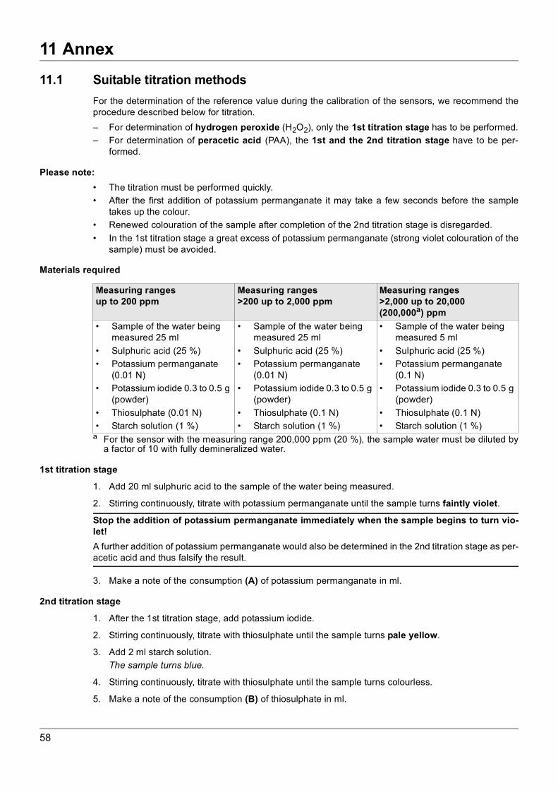
11 Annex
11 Annex
11.1 Suitable titration methodsFor the determination of the reference value during the calibration of the sensors, we recommend theprocedure described below for titration.– For determination of hydrogen peroxide (H2O2), only the 1st titration stage has to be performed.– For determination of peracetic acid (PAA), the 1st and the 2nd titration stage have to be per-
formed.
Please note:• The titration must be performed quickly.• After the first addition of potassium permanganate it may take a few seconds before the sample
takes up the colour.• Renewed colouration of the sample after completion of the 2nd titration stage is disregarded.• In the 1st titration stage a great excess of potassium permanganate (strong violet colouration of the
sample) must be avoided.
Materials required
1st titration stage
1. Add 20 ml sulphuric acid to the sample of the water being measured.
2. Stirring continuously, titrate with potassium permanganate until the sample turns faintly violet.
Stop the addition of potassium permanganate immediately when the sample begins to turn vio-let!A further addition of potassium permanganate would also be determined in the 2nd titration stage as per-acetic acid and thus falsify the result.
3. Make a note of the consumption (A) of potassium permanganate in ml.
2nd titration stage
1. After the 1st titration stage, add potassium iodide.
2. Stirring continuously, titrate with thiosulphate until the sample turns pale yellow.
3. Add 2 ml starch solution.The sample turns blue.
4. Stirring continuously, titrate with thiosulphate until the sample turns colourless.
5. Make a note of the consumption (B) of thiosulphate in ml.
Measuring rangesup to 200 ppm
Measuring ranges>200 up to 2,000 ppm
Measuring ranges>2,000 up to 20,000 (200,000a) ppm
a For the sensor with the measuring range 200,000 ppm (20 %), the sample water must be diluted bya factor of 10 with fully demineralized water.
• Sample of the water being measured 25 ml
• Sulphuric acid (25 %)• Potassium permanganate
(0.01 N)• Potassium iodide 0.3 to 0.5 g
(powder)• Thiosulphate (0.01 N)• Starch solution (1 %)
• Sample of the water being measured 25 ml
• Sulphuric acid (25 %)• Potassium permanganate
(0.01 N)• Potassium iodide 0.3 to 0.5 g
(powder)• Thiosulphate (0.1 N)• Starch solution (1 %)
• Sample of the water being measured 5 ml
• Sulphuric acid (25 %)• Potassium permanganate
(0.1 N)• Potassium iodide 0.3 to 0.5 g
(powder)• Thiosulphate (0.1 N)• Starch solution (1 %)
58
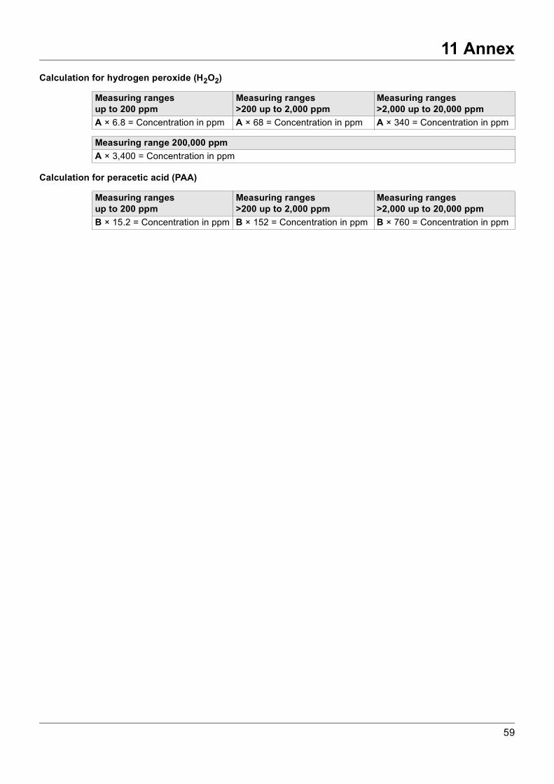
11 Annex
Calculation for hydrogen peroxide (H2O2)Calculation for peracetic acid (PAA)
Measuring rangesup to 200 ppm
Measuring ranges>200 up to 2,000 ppm
Measuring ranges>2,000 up to 20,000 ppm
A × 6.8 = Concentration in ppm A × 68 = Concentration in ppm A × 340 = Concentration in ppm
Measuring range 200,000 ppmA × 3,400 = Concentration in ppm
Measuring rangesup to 200 ppm
Measuring ranges>200 up to 2,000 ppm
Measuring ranges>2,000 up to 20,000 ppm
B × 15.2 = Concentration in ppm B × 152 = Concentration in ppm B × 760 = Concentration in ppm
59
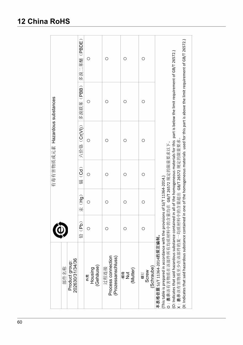
12 China RoHS
12 China RoHS
60


JUMO GmbH & Co. KG JUMO Instrument Co. Ltd. JUMO Process Control, Inc.Street address: Moritz-Juchheim-Straße 136039 Fulda, Germany
JUMO HouseTemple Bank, RiverwayHarlow, Essex, CM20 2DY, UK
6733 Myers RoadEast Syracuse, NY 13057, USA
Delivery address: Mackenrodtstraße 1436039 Fulda, Germany
Phone:Fax:Email:Internet:
+44 1279 63 55 33+44 1279 62 50 [email protected]
Phone:Fax:Email:Internet:
+1 315 437 5866+1 315 437 [email protected] address:
36035 Fulda, GermanyPhone:Fax:Email:Internet:
+49 661 6003-0+49 661 [email protected]

![Stérilisation Basse Température au Peroxyde …...Caractéristiques équipements 14937-6 Sterrad NX® Sterrad 100NX® Vol utile 30 L 100 L [H2O2] 59% Condenseur [H2O2] = à 94% [H2O2]](https://img.dokumen.tips/doc/110x75/5e5477ffc9521448a16205b9/strilisation-basse-temprature-au-peroxyde-caractristiques-quipements.jpg)