Embed Size (px)
Citation preview
NOT MEASUREMENTSENSITIVE
DOE-STD-1066-99July 1999
SupersedingDOE-STD-1066-97
DOE STANDARD
FIRE PROTECTION DESIGN CRITERIA
U.S. Department of Energy AREA FIRPWashington, D.C. 20585
DISTRIBUTION STATEMENT. Approved for public release; distribution is unlimited.
This document has been reproduced from the best available copy.
Available to DOE and DOE contractors from ES&H Technical Information Services,U.S. Department of Energy, (800) 473-4375, fax: (301) 903-9823.
Available to the public from the U.S. Department of Commerce, TechnologyAdministration, National Technical Information Service, Springfield, VA 22161;(703) 605-6000.
DOE-STD-1066-99
iii
FOREWORD
This Department of Energy (DOE) Standard is approved for use by all DOE elements and theircontractors.
DOE Standards are part of the DOE Directives System and are issued to provide supplementalguidance regarding the Department's expectations for fulfilling its requirements as contained in rules,Orders, and notices. The Standards provide acceptable methods for implementing theserequirements.
Beneficial comments (recommendations, additions, deletions) and any pertinent data that may improvethis document should be sent to the name and address below by letter or by using the self-addressedDocument Improvement Proposal (DOE F 1300.3) appearing at the end of this document.
Dennis KubickiOffice of Environment, Safety and HealthOffice of Occupational Health and Safety Policy Bellemead BuildingU.S. Department of Energy19901 Germantown RoadGermantown, MD 20874-1290

DOE-STD-1066-99
iv
INTENTIONALLY BLANK
DOE-STD-1066-99
v
TABLE OF CONTENTSSection Page1. SCOPE . . . . . . . . . . . . . . . . . . . . . . . . . . . . . . . . . . . . . . . . . . . . . . . . . . . . . . . . . . . . . . . . 1
2. PURPOSE . . . . . . . . . . . . . . . . . . . . . . . . . . . . . . . . . . . . . . . . . . . . . . . . . . . . . . . . . . . . . 1
3. REFERENCED CRITERIA . . . . . . . . . . . . . . . . . . . . . . . . . . . . . . . . . . . . . . . . . . . . . . . . . 2
4. DEFINITIONS . . . . . . . . . . . . . . . . . . . . . . . . . . . . . . . . . . . . . . . . . . . . . . . . . . . . . . . . . . . 4
5. GENERAL FIRE PROTECTION DESIGN CRITERIA . . . . . . . . . . . . . . . . . . . . . . . . . . . . . 9
5.1 Protection to Limit Loss Potential . . . . . . . . . . . . . . . . . . . . . . . . . . . . . . . . . . . . . . . 95.2 Structural Considerations . . . . . . . . . . . . . . . . . . . . . . . . . . . . . . . . . . . . . . . . . . . . . 95.3 Fire Suppression Systems . . . . . . . . . . . . . . . . . . . . . . . . . . . . . . . . . . . . . . . . . . . 10
6. WATER SUPPLY AND DISTRIBUTION SYSTEMS . . . . . . . . . . . . . . . . . . . . . . . . . . . . . 11
6.1 Demand . . . . . . . . . . . . . . . . . . . . . . . . . . . . . . . . . . . . . . . . . . . . . . . . . . . . . . . . . 116.2 System Arrangement . . . . . . . . . . . . . . . . . . . . . . . . . . . . . . . . . . . . . . . . . . . . . . . 12
7. AUTOMATIC SPRINKLER SYSTEMS . . . . . . . . . . . . . . . . . . . . . . . . . . . . . . . . . . . . . . . 12
8. FIRE ALARM SYSTEMS . . . . . . . . . . . . . . . . . . . . . . . . . . . . . . . . . . . . . . . . . . . . . . . . . 13
8.1 General Features . . . . . . . . . . . . . . . . . . . . . . . . . . . . . . . . . . . . . . . . . . . . . . . . . . 138.2 Alarm Actuating Devices . . . . . . . . . . . . . . . . . . . . . . . . . . . . . . . . . . . . . . . . . . . . 138.3 Alarm System Extensions . . . . . . . . . . . . . . . . . . . . . . . . . . . . . . . . . . . . . . . . . . . . 14
9. STRUCTURAL FIRE PROTECTION CRITERIA . . . . . . . . . . . . . . . . . . . . . . . . . . . . . . . . 14
9.1 General . . . . . . . . . . . . . . . . . . . . . . . . . . . . . . . . . . . . . . . . . . . . . . . . . . . . . . . . . 149.2 Fire Barriers . . . . . . . . . . . . . . . . . . . . . . . . . . . . . . . . . . . . . . . . . . . . . . . . . . . . . . 149.3 Flame Spread . . . . . . . . . . . . . . . . . . . . . . . . . . . . . . . . . . . . . . . . . . . . . . . . . . . . . 159.4 Roofing Systems . . . . . . . . . . . . . . . . . . . . . . . . . . . . . . . . . . . . . . . . . . . . . . . . . . 159.5 Penetrations . . . . . . . . . . . . . . . . . . . . . . . . . . . . . . . . . . . . . . . . . . . . . . . . . . . . . . 159.6 Carpets and Rugs . . . . . . . . . . . . . . . . . . . . . . . . . . . . . . . . . . . . . . . . . . . . . . . . . 15
10. LIFE SAFETY . . . . . . . . . . . . . . . . . . . . . . . . . . . . . . . . . . . . . . . . . . . . . . . . . . . . . . . . . . 16
11. ELECTRICAL EQUIPMENT . . . . . . . . . . . . . . . . . . . . . . . . . . . . . . . . . . . . . . . . . . . . . . . 17
12. GENERAL PROCESS HAZARD FIRE PROTECTION . . . . . . . . . . . . . . . . . . . . . . . . . . . 17
DOE-STD-1066-99
vi
TABLE OF CONTENTS (CONTINUED)Section Page13. SPECIAL HAZARDS . . . . . . . . . . . . . . . . . . . . . . . . . . . . . . . . . . . . . . . . . . . . . . . . . . . . . 18
13.1 General . . . . . . . . . . . . . . . . . . . . . . . . . . . . . . . . . . . . . . . . . . . . . . . . . . . . . . . . . 1813.2 Plutonium Processing and Handling Facilities (PPHF) . . . . . . . . . . . . . . . . . . . . . . 1813.3 Plutonium Storage Facilities (PSF) . . . . . . . . . . . . . . . . . . . . . . . . . . . . . . . . . . . . . 1813.4 Enriched Uranium Storage Facilities (EUSF) . . . . . . . . . . . . . . . . . . . . . . . . . . . . . 1813.5 Uranium Processing and Handling Facilities . . . . . . . . . . . . . . . . . . . . . . . . . . . . . . 1813.6 Reprocessing Facilities . . . . . . . . . . . . . . . . . . . . . . . . . . . . . . . . . . . . . . . . . . . . . . 1913.7 Uranium Conversion and Recovery Facilities . . . . . . . . . . . . . . . . . . . . . . . . . . . . . 19
14. NUCLEAR FILTER PLENUM FIRE PROTECTION . . . . . . . . . . . . . . . . . . . . . . . . . . . . . 19
14.1 Purpose and Scope . . . . . . . . . . . . . . . . . . . . . . . . . . . . . . . . . . . . . . . . . . . . . . . . 1914.2 Filter Plenum Construction . . . . . . . . . . . . . . . . . . . . . . . . . . . . . . . . . . . . . . . . . . . 2014.3 Location of Final Filter Plenum Ventilation System Equipment . . . . . . . . . . . . . . . . 2014.4 Protection of Openings in Fire Rated Construction . . . . . . . . . . . . . . . . . . . . . . . . . 2114.5 Materials and Special Hazards Inside Plenums . . . . . . . . . . . . . . . . . . . . . . . . . . . 2214.6 Prefilters, Duct Entrance Filters, and Fire Screens . . . . . . . . . . . . . . . . . . . . . . . . . 2314.7 Detection Systems . . . . . . . . . . . . . . . . . . . . . . . . . . . . . . . . . . . . . . . . . . . . . . . . . 2514.8 Deluge Spray Suppression Systems . . . . . . . . . . . . . . . . . . . . . . . . . . . . . . . . . . . 2614.9 Special System Guidelines . . . . . . . . . . . . . . . . . . . . . . . . . . . . . . . . . . . . . . . . . . . 2914.10 Fire Hazard Analysis . . . . . . . . . . . . . . . . . . . . . . . . . . . . . . . . . . . . . . . . . . . . . . . 30
15. GLOVEBOX FIRE PROTECTION . . . . . . . . . . . . . . . . . . . . . . . . . . . . . . . . . . . . . . . . . . 31
15.1 Scope . . . . . . . . . . . . . . . . . . . . . . . . . . . . . . . . . . . . . . . . . . . . . . . . . . . . . . . . . . . 3115.2 Glovebox Construction . . . . . . . . . . . . . . . . . . . . . . . . . . . . . . . . . . . . . . . . . . . . . . 3115.3 Automatic Fire Suppression/Inerting Systems . . . . . . . . . . . . . . . . . . . . . . . . . . . . 3415.4 Manual Fire Suppression . . . . . . . . . . . . . . . . . . . . . . . . . . . . . . . . . . . . . . . . . . . . 3815.5 Fire Detection Systems . . . . . . . . . . . . . . . . . . . . . . . . . . . . . . . . . . . . . . . . . . . . . 3915.6 Glovebox Ventilation . . . . . . . . . . . . . . . . . . . . . . . . . . . . . . . . . . . . . . . . . . . . . . . . 40
Appendices
Appendix A. Nuclear Filtration and Air Cleaning Systems . . . . . . . . . . . . . . . . . . . . . . . . . . A-1Appendix B. Operating Temperatures for HEPA Filters . . . . . . . . . . . . . . . . . . . . . . . . . . . . B-1Appendix C. General Criteria Summary Table and Plan Diagram . . . . . . . . . . . . . . . . . . . . C-1Appendix D. Discussion on Evaluating Duct Openings When Penetrating 2-Hour
Fire Walls . . . . . . . . . . . . . . . . . . . . . . . . . . . . . . . . . . . . . . . . . . . . . . . . . . . . D-1Appendix E. Example Glovebox Fire Detection Systems . . . . . . . . . . . . . . . . . . . . . . . . . . . E-1Appendix F. Fire Extinguisher Quick Disconnect Coupling . . . . . . . . . . . . . . . . . . . . . . . . . . F-1Appendix G. Dry Powder Extinguishing Agent Holder . . . . . . . . . . . . . . . . . . . . . . . . . . . . . G-1Appendix H. Limited Water Sprinkler Design . . . . . . . . . . . . . . . . . . . . . . . . . . . . . . . . . . . . H-1Appendix I. Glovebox Window Material Comparison . . . . . . . . . . . . . . . . . . . . . . . . . . . . . . . I-1Appendix J. Glovebox Overpressure Protection Valves . . . . . . . . . . . . . . . . . . . . . . . . . . . . J-1Appendix K. Glovebox Fire Protection Survey . . . . . . . . . . . . . . . . . . . . . . . . . . . . . . . . . . . K-1Appendix L. References . . . . . . . . . . . . . . . . . . . . . . . . . . . . . . . . . . . . . . . . . . . . . . . . . . . . L-1
DOE-STD-1066-99
1
1. SCOPE The provisions of this Standard apply as guidance to the following: a. All departmental elements as delineated in the scope of DOE 420.1, "Facility Safety," and DOE
440.1, "Worker Protection Management for DOE and Contractor Employees," and theirrespective Contractor Requirements Documents (CRD).
b. The purchase and lease, as well as the design and construction, of all DOE facilities erected,modified, or renovated after the effective date of this Standard.
Nothing in this Standard is intended to limit the application of other fire protection methodswhen unique situations or hazards warrant an alternate approach. The alternate approachshould provide a comparable level of safety to that achieved by conformance with thisStandard. Such alternate approaches should be approved by the Authority Having Jurisdiction (AHJ),after consultation with a qualified fire protection engineer. 2. PURPOSE The development of this Standard reflects the fact that national consensus standards and other designcriteria do not comprehensively or, in some cases, adequately address fire protection issues at DOEfacilities. This Standard provides supplemental fire protection guidance applicable to the design andconstruction of DOE facilities and site features (such as water distribution systems) that are alsoprovided for fire protection. It is intended to be used in conjunction with the applicable buildingcode, National Fire Protection Association (NFPA) Codes and Standards, and any otherapplicable DOE construction criteria. This Standard replaces certain mandatory fire protection requirements that were formerly in DOE5480.7A, "Fire Protection," and DOE 6430.1A, "General Design Criteria." It also contains the fireprotection guidelines from two (now canceled) draft standards: "Glove Box Fire Protection" and "FilterPlenum Fire Protection." (Note: This Standard does not supersede the requirements of DOE 5480.7Aand DOE 6430.1A where these DOE Orders are currently applicable under existing contracts.) This Standard, along with the criteria delineated in Section 3, constitutes the basic criteria forsatisfying DOE fire and life safety objectives for the design and construction or renovation of DOEfacilities.
DOE-STD-1066-99
2
3. REFERENCED CRITERIA DOE facilities and their associated fire protection features are subject to the applicable sections of thecurrent editions of the criteria listed below. Federal Criteria o 29 CFR Part 1910, "Occupational Safety & Health Standards" o 29 CFR Part 1926, "Safety & Health Regulations for Construction"
o Americans with Disabilities Act Accessibility Guidelines (ADAAG)
o Other statutory requirements, not listed above, that delineate criteria of a more limited extentrelating to facility fire safety.
DOE Requirements o DOE O 420.1, "Facility Safety"
o DOE O 420.1, "Contractor Requirements Document"
o DOE O 440.1, "Worker Protection Management for Federal and Contractor Employees" o DOE O 440.1, "Contractor Requirements Document"
o DOE M 440.1-1, "DOE Explosives Safety Manual"
o DOE 5480.7A, "Fire Protection" (Applicable under some existing contracts)
o DOE 6430.1A, "General Design Criteria" (Applicable under some existing contracts)
o DOE/EV/06194, "DOE Explosives Safety Manual" (Applicable under some existing contracts)
o Other DOE Orders, not listed above, that delineate criteria of a more limited extent that relateto facility fire safety.
DOE Guidelines o DOE-HDBK-1062-96, "DOE Fire Protection Handbook"
o DOE-HDBK-1081-94, "Primer on Spontaneous Heating and Pyrophoricity"
o DOE-STD-1020-94, "Natural Phenomenon Hazards Design and Evaluation Criteria"
o DOE-STD-1088-95, "Fire Protection for Relocatable Structures"
o G-420.1/B-0, "Implementation Guide for use with DOE Orders 420.1 and 440.1 Fire SafetyProgram"
DOE-STD-1066-99
3
Other Criteria o National Fire Protection Association Codes and Standards
o State and Local Building and Fire Codes applicable in the area (Uniform Building Code if no localbuilding code exists)
o National Fire Protection Association Handbooks, Guides and Recommended Practices
o Factory Mutual Loss Prevention Data Sheets
o Society of Fire Protection Engineers Handbook
o USNRC Guidelines on Fire Protection for Fuel Cycle Facilities, (Vol.) 57 Federal Register,(Pages) 35607-13, August 10, 1992
Referenced Standards American Society for Testing and Materials (ASTM) ASTM E-84 Standard Test Method for Surface Burning Characteristics of Building Materials ASTM E-119 Standard Method of Fire Tests of Building Construction and Materials ASTM E-136 Tests of Behavior of Materials in a Vertical Tube Furnace at 750 Degrees Celsius ASTM E-176 Standard Terminology of Fire Standards ASTM E-814 Fire Tests of Through Penetration Stops
ASTM C-852 Standard Design Criteria for Plutonium Gloveboxes American Society of Mechanical Engineers (ASME) ASME AG-1-1994 Code on Nuclear Air and Gas Treatment (revision of ASME AG-1-1991) Institute of Electrical and Electronics Engineers (IEEE) IEEE-399 Recommended Practice for Industrial and Commercial Power System Analysis IEEE-493 Recommended Practice for the Design of Reliable Industrial and Commercial Power
Systems Underwriters Laboratories, Inc. (UL) Standards UL-555 Standard for Fire Dampers and Ceiling Dampers UL-586 High Efficiency Particulate Air-Filter Units UL-900 Test Performance of Air Filter Units
DOE-STD-1066-99
4
4. DEFINITIONS Acceptable - When applied to fire safety, "acceptable" is a level of protection which the AuthorityHaving Jurisdiction, after consultation with the cognizant DOE fire protection engineer(s), considerssufficient to achieve the fire and life safety objectives defined in DOE Orders. In some instances, itis a level of protection necessary to meet a code or standard. In other instances, it is a level ofprotection that deviates (plus or minus) from a code or standard as necessary and yet adequatelyprotects against the inherent fire hazards. Adsorber Systems - A system for removing gases or vapors from air by means ofpreferential physical condensation and retention of molecules on a solid surface. Adsorbers used innuclear applications are often impregnated with chemicals to increase their activity for organicradioactive iodine compounds. Authority Having Jurisdiction (AHJ) - The decision making authority in matters concerning fireprotection. The DOE Head of Field Organization or designee is the final AHJ unless otherwisedirected by the Cognizant Secretarial Officer. Combustible Liquid - A liquid having a closed cup flash point at or above 100 oF (38 oC). Combustible Material - Any material that will ignite and burn. Any material that does not comply withthe definition of "noncombustible" as contained in this Standard is considered combustible. The termcombustible is not related to any specific ignition temperature or flame spread rating. Criticality Incident - The release of energy as a result of accidentally producing a self-sustaining ordivergent neutron chain reaction. Deep Bed Fiberglass Filter - A ventilation filter made of deep beds of compacted fiberglass containedin stainless steel boxes having opaque sides and perforated screens at the top and bottom for theremoval of particulate matter. Deep Bed Sand Filter - Particulate filter constructed of deep beds of rock, gravel, and sand, formedin layers graded with about two to one variation in granule size from layer to layer. Demister - A device used to protect the final filter in an air cleaning system from entrained moisturein the air.
(Note: Demisters for fire protection purposes are usually perforated bent plate type mist eliminatorsfabricated by taking two flat perforated metal sheets spot-welded together and uniformly spacing thema few thousandths of an inch apart, with perforations in adjacent sheets offset so that air entering theholes in the first sheet impinges on the second sheet and must make two 90 degree turns before itcan escape. The two perforated metal sheets are then bent or pleated with saw tooth angles of 45degrees to increase the surface area per square foot of frontal area. Moisture from a perforated platetype mist demister is removed by impingement of droplets on the water film flowing down between thesheets and on the face of the first sheet. Perforated bent plate-type demisters must be installed withthe pleats in the vertical position so that water can flow off them easily.) Duct Entrance Filter - A filter unit installed at the exhaust duct entrance(s) to prevent entrance andaccumulation of combustible or flammable dusts and/or residues inside the exhaust ducts.
DOE-STD-1066-99
5
(Note: This is a concern of particular interest to the nuclear industry because radioactive substancestend to deposit or "plate out" on ducts. Dust accumulation inside duct surfaces can create fires thatare serious because they occur in the ventilation system leading directly to the final exhaust plenumfilters.)
Exhaust Plenum Final Filter - The final filter unit in a set of filters arranged in a series for ventilationand effluent discharge in an air cleaning system. Fire Area - A location bounded by construction having a minimum fire resistance rating of 2 hours withopenings protected by appropriately fire-rated doors, windows, dampers, or penetration seals. Theboundaries of exterior fire areas (yard areas) or other locations that represent unique conditionsshould be as determined by the cognizant fire protection engineer (contractor or DOE). Fire Loss - The dollar cost of restoring damaged property to its pre-fire condition. When determiningloss, the estimated damage to the facility and contents should include replacement cost, less salvagevalue. Fire loss should exclude the costs for:
o property scheduled for demolition; and o decommissioned property not carried on books as a value.
Fire loss should include the cost of:
o decontamination and cleanup; o the loss of production or program continuity; o the indirect costs of fire extinguishment (such as damaged fire department equipment); and o the effects on related areas.
Fire Protection Engineer - A graduate of an accredited engineering curriculum and having completednot less than 4 years of engineering practice, 3 of which shall have been in responsible charge ofdiverse fire protection engineering work. If not such a graduate, a qualified engineer shall either:demonstrate a knowledge of the principles of engineering and have completed not less than 6 yearsengineering practice, 3 of which shall have been in responsible charge of diverse fire protectionengineering projects; be a registered professional engineer in fire protection; or meet the requirementsfor a Grade 11 or higher Fire Protection Engineer as defined by the Office of Personnel Management. Fire Protection System - Any system designed to detect and contain or extinguish a fire, as well aslimit the extent of fire damage and enhance life safety. Fire Resistance Rating - The time that a particular construction will withstand a standard fire exposurein hours as determined by ASTM E-119. Fire Screen - An item of equipment installed ahead of all HEPA filter banks intended to reduce flamepropagation and glowing/burning ember products from reaching final high efficiency particulate air(HEPA) filters. Flammable Liquid - A liquid having a closed cup flash point below 100 bF (38 oC) and having a vaporpressure not exceeding 40 psia (2068 mm Hg) at 100 oF (38 oC). Flame Spread Rating - Flame spread rating is a numerical classification determined by the testmethod in ASTM E-84, which indexes the relative burning behavior of a material by quantifying the
DOE-STD-1066-99
6
spread of flame of a test specimen. The surface burning characteristic of a material is not a measureof resistance to fire exposure.
Glovebox - A sealed enclosure with viewing windows designed to separate the space in the enclosurefrom its surroundings and in which all items in the enclosure are handled using gloves that are sealedto the enclosure walls. Heat Resistant - A material having the quality or capability of withstanding heat for a specified periodat a maximum given temperature without decomposing or losing its integrity. High Efficiency Metal Fiber (HEMF) Filter - A reusable metal filter composed of fine sintered stainlesssteel fibers together with a stainless steel wire and metal support housing and pleated to enhancestrength, surface area, and particle holding capacity. High Efficiency Particulate Air (HEPA) Filter - A disposable extended pleated medium dry type filterwith a rigid housing having a minimum particle removal efficiency of at least 99.97 percent (maximumpenetration of 0.03%) for particles of 0.3 microns or greater (by light scattering mean droplet diameter)when tested with monodisperse dioctylphthalate (DOP) smoke and maximum pressure drop of 1.0inch (2.54 centimeters) of water when clean and operated at its rated airflow capacity. HEPA filtersconsist of a material that is a thin mat of fine intertwined glass fibers that are folded back and fortharound separators, and then enclosed by a plywood or metal frame. HEPA filters are easily damagedby very high temperatures and aerosols, and can fail when subjected to moisture and/or structuralloading. From ASME AG-1-1994: A throwaway, extended-media dry-type filter with a rigid casing enclosing thefull depth of the pleats. The filter shall exhibit a minimum efficiency of 99.7% when tested with anaerosol of essentially monodispersed 0.3 micron test aerosol particles. Hydrophoric Materials - Materials that react violently with water or water vapor (such as lithium andlithium hydride). Limited Supply Suppression System - A system installed in accordance with the applicable NFPAStandards and having a limited quantity of suppression agent. These systems typically include carbondioxide, dry chemical, other gaseous agents, or water. Listed/Approved - Equipment or materials that have been tested, passed, and are included in acurrent list published by a nationally recognized testing laboratory which is concerned with productevaluation and is acceptable to the AHJ. The laboratory maintains periodic inspection of productionof listed equipment or materials. Such lists state either that the equipment or material meetsappropriate standards or has been tested and found suitable for use in a specified manner. Thisdefinition applies to products which are Underwriter's Laboratories (UL) listed or Factory Mutual (FM)approved. Maximum Possible Fire Loss (MPFL) - The value of property, excluding land value, within a fire area,unless a fire hazards analysis demonstrates a lesser (or greater) loss potential. This assumes thefailure of both automatic fire suppression systems and manual fire fighting efforts. Noncombustible - A material that in the form in which it is used and under the conditions anticipatedwill not ignite, burn, support combustion, or release flammable vapors when subjected to fire or heat,
DOE-STD-1066-99
7
as defined by fire protection industry standards on the basis of large scale fire tests performed by anationally recognized independent fire test authority. Occupancy - The purpose for which a building, or portion thereof, is used or intended to be used. ForDOE facilities, the occupancy classification for purposes of determining construction, protection andarea limitations should be as determined under the provisions of the applicable local building code orthe Uniform Building Code unless otherwise specified by the AHJ. Prefilter - A filter that is located upstream from another filter. Prefilters, or roughing filters, removeand/or reduce the percentage of large particles that would reduce the life of the next-in-line or finalfilters. (Note: Although final HEPA filters are excellent collectors of very small particles, they are likely to plugwhen subjected to high loads of dust and large smoke particles generated in a fire. Prefilters helpremove the large particles and dust that would accumulate on the HEPA filters. Prefilters cangenerally be located at any point in the exhaust ventilation system before the final HEPA filters andsometimes are located in the final filter plenum enclosure.) Pyrophoric Material - A material with an autoignition temperature in air at or below 130 degrees F(54.4 degrees C) and 50% relative humidity. Redundant Fire Protection System - A fire protection system that is designed and installed to functionin the event of the failure of a primary fire protection system. Where redundant fire protection systemsare specified, any two of the following are considered satisfactory:
o Automatic suppression systems, such as fire sprinklers, foam, gaseous, explosion suppression,or other specialized extinguishing systems plus appropriate alarms. An adequate supply,storage, and distribution system is an essential element.
o Automatic fire detection, occupant warning, manual fire alarm, and fire alarm reporting systems
(considered together) combined with a sufficiently-staffed, properly-equipped and adequately-trained fire department or brigade that is able and committed to respond in a timely and effectivemanner.
o Fire barrier systems or combinations of physical separation and barriers for outdoor locations.
o Other systems, such as alternate process control systems, as approved by the AHJ.
Redundant fire protection systems may include dual water supplies to sprinkler systems, dual pipingrisers, or valving systems such that adequate redundancy in water supply to the sprinkler heads isprovided to cover maintenance or emergency outages of either of the water supply systems or mayinclude multiple types of automatic fire suppression systems (e.g., water sprinklers and a gaseous firesuppression system). Portable fire extinguishers, interior fire hose systems, or interior fire detection and alarm systems donot meet the definition of a redundant fire protection system. Smoke Developed Rating - Smoke developed rating is a numerical classification determined by ASTME-84, which indexes the smoke generation rate of a given material to those of two standard materials(inorganic reinforced cement board and select grade red oak).
DOE-STD-1066-99
8
Special Facilities - As used in this standard, the term "special facilities" includes the following:
o Emergency Preparedness Facilities
o Explosives Facilities
o Fusion Facilities
o Hazardous Waste Incinerator Facilities
o Irradiated Fissile Material Storage Facilities
o Laboratory Facilities (Including Hot Laboratories)
o Nonreactor Nuclear Facilities
o Plutonium Processing and Handling Facilities
o Plutonium Storage Facilities
o Radioactive Liquid Waste Facilities
o Radioactive Solid Waste Facilities
o Reprocessing Facilities
o RCRA Storage Facilities
o Secure Conference Rooms
o Telecommunications, Alarm, Central Data Processing Centers and Radio Repeater Stations
o Tritium Facilities
o Unirradiated Enriched Uranium Storage Facilities
o Uranium Conversion and Recovery Facilities
o Uranium Enrichment Facilities
o Uranium Processing and Handling Facilities
o Vaults and Vault-type Rooms for Storage of Classified Matter
o Other Facilities as Defined by the AHJ
DOE-STD-1066-99
9
5. GENERAL CRITERIA
5.1 Protection to Limit Loss Potential
5.1.1 When the Maximum Possible Fire Loss (MPFL) exceeds $50 million, a redundant fireprotection system should be provided that, despite the failure of the primary fireprotection system, will limit the loss to acceptable levels as determined by theAuthority Having Jurisdiction (AHJ).
5.1.2 When the MPFL exceeds $150 million, a redundant fire protection system and a 3-hour fire barrier should be provided to limit the MPFL to acceptable levels asdetermined by the AHJ.
5.1.3 Where a potential fire would represent an unacceptable risk to the health and safetyof the public, workers, the environment, DOE programs or DOE property (asdetermined by a fire hazard analysis) fire protection should be provided for specialstructures, commensurate with the risk. (Refer also to DOE-STD-1088-95, "FireProtection for Relocatable Structures.")
5.1.4 All DOE sites and facilities should have access to a fully-staffed, completely-equipped and adequately-trained fire department that is capable and committed torespond to fires and related emergencies on site in a timely and effective manner.If, on the basis of a "Needs Assessment" or "Operational Basis Document" (Refer toDOE O 420.1, "Facility Safety."), it is determined that such a capability does not existand that DOE is, consequently, subject to a higher loss potential, additional fireprotection features should be provided to compensate for the deficiencies determined.The fire department capability to reduce loss due to a fire should be considered interms of the following factors:
o location of fire station(s) with respect to the facility to be protected;
o staffing of stations (e.g., continuously or "on-call volunteer");
o ability to perform initial fire attack as outlined in NFPA 1410;
o method(s) of fire department notification or alarm reception; and
o familiarity of station staff with the DOE facility, and training in preparation foreffective response to an alarm at the DOE facility.
5.2 Structural Considerations
5.2.1 New permanent structures in excess of 5,000 square feet floor area should be ofnoncombustible or fire resistive construction if no local building code is enforced.
5.2.2 Interior fire barriers should be provided to isolate hazardous occupancies, to minimizethe potential for fire spread (including products of combustion) and loss potential, andto help assure the orderly evacuation of facility occupants, consistent with theconclusions of the Fire Hazards Analysis (FHA) that is performed in conjunction withthe design process. Openings in such barriers should be protected with appropriately
DOE-STD-1066-99
10
fire-rated doors, windows, dampers or penetration seals. (Refer to the applicablebuilding code.)
5.2.3 To protect the integrity of the physical barriers associated with process confinementsystems, fire protection features should include the following:
o A fire-extinguishing system to rapidly remove heat produced by fire to preventor minimize the pressurization of a process confinement and to rapidly extinguisha fire to minimize the loading of ventilation system filters with combustionproducts.
o The introduction of the extinguishing agent in a way that does not result inover-pressurization of the confinement barriers.
5.3 Fire Suppression Systems
5.3.1 All facilities of significance, including facilities where a fire could cause unacceptableoff-site consequences to health and safety, should be protected by an automatic firesuppression system (usually a Wet Pipe Sprinkler System). A decision to installanother type of fire suppression system should be based on engineering analysisperformed by a fire protection engineer. DOE has, historically, considered an facilitywith an MPFL in excess of $1 million as being significant from a property protectionstandpoint.
5.3.2 In some circumstances, the need for automatic fire suppression systems should beconsidered, despite the absence of explicit requirements, such as when the MPFL isbelow $1 million or other limits imposed by DOE. Some examples of situations whereautomatic fire suppression systems may be warranted are :
o facilities that contain critical or long procurement time construction items;
o a temporary-use trailer used as a control center for a vital one-time activity;
o a facility with high public visibility or sensitivity (as defined by the AHJ);
o electric power transformers with combustible contents that, of damaged, couldresult in an extended shut-down of the facilities they serve;
o facilities in which a fire could result in the accidental release of significantquantities of toxic or hazardous materials or emissions (based on engineeringanalysis);
o facilities that can be protected by extending automatic fire suppression systemsfrom an adjacent protected facility or area at a low incremental cost;
o facilities in which a fire could damage more important adjacent facilities;
o facilities used to store hard to replace or irreplaceable records;
o facilities that may warrant automatic fire suppression systems in the future; and
DOE-STD-1066-99
11
o facilities where required for protection of human life.
5.3.3 Where required by the Safety Analysis Report (SAR), the design of fire protectionsystems to withstand seismic events should be in accordance the criteria developedby the National Fire Protection Association, except as required by other DOE criteria,such as in Section 7 of this standard.
5.3.4 Fire protection systems, or portions of them, that must function to control effects ofa Design Basis Accident (DBA) event (as determined by safety analysis accidentscenarios) should be designed to be functional for all conditions included in theaccident scenario. This should include both the event initial cause and itsconsequences.
5.3.5 When the use of water sprinkler coverage is precluded because of nuclear criticalityor other incompatibility reasons, nonaqueous extinguishing systems (e.g., inert gas,carbon dioxide, Halon alternatives, etc.) should be used.
5.3.6 Standpipes should be installed in all structures having three levels or more above orbelow grade. Standpipe systems should be provided in other structures, such asthose with extensive and complex interior layouts, where deemed necessary by theDOE Fire Protection AHJ. Standpipes should be designed and installed as Class 1systems per NFPA 14.
6. WATER SUPPLY AND DISTRIBUTION SYSTEM CRITERIA
6.1 Demand
6.1.1 Domestic water distribution systems that also serve fire protection requirementsshould be designed to satisfy the calculated Fire Hydrant Demand (see Paragraph6.1.2) and the peak domestic demand. Where no other requirements are applicable,the peak domestic demand should be based on 2.5 times the calculated average dailydemand plus any special demands, such as industrial or processes that cannot bereduced during a fire. The distribution system should be capable of meeting thiscombined demand at a minimum residual pressure of 20 psi at ground elevation (orhigher elevation if special conditions apply) for a period of not less than 2 hours.Municipal supplies having the same capability are acceptable.
6.1.2 Fire Hydrant Demand - Where reliance is placed on fire department response, eitherfor protection of unsprinklered buildings or where the fire department will serve asredundant (backup) protection, the water supply available from hydrants should becapable of providing the flow rates established in the Uniform Fire Code based on themost severe facility fire risk on site. These values may be reduced by a maximum of50% when the facility is provided with automatic sprinkler protection throughout, inaccordance with the applicable NFPA Standards.
6.1.3 Within a building or facility, domestic water should be supplied by a separate serviceline and not be a combined fire protection and potable water service or a combinedprocess water and potable water system. Where combined fire and domestic-processwater systems are used, distribution piping should be routed and provided with valves
DOE-STD-1066-99
12
such that the domestic and process systems can be isolated without shutting off thefire system supply.
6.2 System Arrangement
6.2.1 Facilities having a Maximum Possible Fire Loss (MPFL) in excess of $100 million andsignificant nuclear facilities (Catagory 1 Hazard) should be provided with anadditional, independent source of fire protection water.
6.2.2 Whenever feasible, all water distribution systems should be of the looped grid typeproviding two-way flow with sectional valving arranged to provide alternate water flowpaths to any point in the system. In addition, sectional control valves should beprovided to limit the number of hydrants and individual sprinkler systems madeinoperative during a single line break to a total of five. Dead end runs utilized as asingle supply to fire hydrants should not exceed 300 feet.
6.2.3 Listed and/or approved control valves should be installed at maximum intervals of notmore than 5,000 feet on long supply lines and at maximum intervals of not more than1200 feet on main distribution loops, feeders and all primary branches connected tothese lines. Such control valves should also be installed at selected points throughoutthe distribution system to provide system control over each service area. Atintersections of distribution mains, one less control valve than the total number ofintersecting mains may be provided. As an aid in determining the minimum numberof sectional control valves, the critical nature of the building/facility should beconsidered as well as the number of fire and domestic systems affected in a potentialline failure.
6.2.4 Sprinkler system water supply lead-ins should not run under buildings except for theminimum distance possible. Sprinkler system risers and alarm valves should belocated as close as practical to a building entry point. Where a riser would otherwisebe located in a potentially contaminated area, consideration should be given tolocating the riser exterior to the building in a heated enclosure.
6.2.5 Hydrants should be provided so that hose runs from hydrants to all exterior portionsof a protected building are no more than 300 feet. Hydrants should not be closer tothan 40 feet to buildings.
7. AUTOMATIC SPRINKLER SYSTEM CRITERIA
7.1 NFPA Standard 13 should be used to determine the occupancy classification for any facility.For facilities where there is a potential for a change in occupancy, light hazard occupancysprinkler system design criteria should not be used.
7.2 Hydraulically designed sprinkler systems should be designed for a supply pressure of at least10% but not less than 10 psi below the supply curve. (Refer to NFPA Standard 13.)
DOE-STD-1066-99
13
7.3 Seismic Criteria
7.3.1 In addition to the applicable seismic requirements delineated in NFPA 13, thefollowing criteria should apply in the design of new sprinkler systems relied upon toprevent or mitigate the adverse nuclear safety consequences of seismically induced:
fires,inadvertent actuations,structural failures, andleakage
as set forth in the facility Safety Analysis Report (SAR).
7.3.2 In the design of sway bracing, the criteria of Section 4-14.4.3.5.3 (or currentequivalent) of NFPA 13 (1996) should be revised as follows. Horizontal force shouldbe determined by the equation F(p) = K x W(p). A value of K consistent with thecriteria in DOE-STD-1020-94 should be determined by an engineer qualified inseismic analysis. Values for K less than 0.5 should not be used unless specificallyjustified. Exception 1 or 2 following Section 4-14.4.3.5.3 should be applied. IfException 1 is applied, use "K" instead of "half." If Exception 2 is applied, divide "K"by 0.5 to determine the multiplier for Table 4-14.4.3.5.3 (or current equivalent).
8. FIRE ALARM SYSTEMS
8.1 General Features
Fire alarm systems should comply with NFPA 72 and have the following basic features:
o Transmission of signals to the responding DOE facility fire department alarm center andother constantly attended locations in accordance with NFPA 72.
o Local alarms for the building or zone in alarm.
o Visual alarms for the hearing impaired, where there are high noise levels, or where thereare special process requirements as determined by the DOE Fire Protection AHJ.
o The fire alarm control panel located near the main entrance or a protected location asdetermined by the AHJ. For buildings with multiple alarm zones, a zone alarm panel or agraphic zone alarm panel at the main entrance to the facility.
o Supervisory devices for all critical functions except those (such as sprinkler system controlvalves) that are locked or sealed. (Refer to NFPA Standard 13.)
8.2 Alarm Actuating Devices
8.2.1 Alarms that respond to flow of water should be provided within a facility for occupantnotification wherever a sprinkler system is installed.
8.2.2 A manual fire notification method, such as telephone, alarm, radio, or manual firealarm boxes, should be provided at all facilities.
DOE-STD-1066-99
14
8.3 Alarm System Extensions
Extensions to existing fire alarm systems and all new systems in existing buildings or facilitiesshould be compatible with existing fire alarm equipment at the location, including keys/locks,similarity of alarm signals and equipment as well as user operated devices, trainingrequirements, and maintenance procedures.
9. STRUCTURAL FIRE PROTECTION CRITERIA
9.1 General
Any materials with unusual fire characteristics, such as urethane foams, and any materialsthat develop significant quantities of toxic or harmful products of combustion (as delineatedin Material Safety Data Sheets and other sources of product information), should not be usedas interior finishes or other interior applications without the approval of the AHJ. The use offoam plastics in construction should be prohibited unless it fully complies with Factory Mutual(FM) Data Sheet 1-57.
9.2 Fire Barriers
9.2.1 Wall, floor and ceiling, and roof and ceiling assemblies should be tested and rated fortheir fire resistance by Underwriter's Laboratories (UL) or similar nationally recognizedtesting laboratories, or should be listed for their fire resistance as approved by FM orsimilar organizations.
9.2.2 Fire Resistance - The development of an FHA and SAR should include considerationof conditions that may exist during normal operations and special situations (e.g.,during periods of decontamination, renovation, modification, repair, andmaintenance). Where required by the FHA or SAR, the structural shell surroundingcritical areas and their supporting members should remain standing and continue toact as a confinement structure during anticipated fire conditions including failure ofany fire suppression system not designed as a safety class item. Fire resistance ofthis shell should be attained by an integral part of the structure (concrete slabs, walls,beams, and columns) and not by composite assembly (membrane fireproofing). Inno event should the fire resistance rating be less than 2 hours under conditions offailure of any fire suppression system not designed as a safety class item. (Refer toNFPA Standard 221 and FM Data Sheet 1-22.)
9.2.3 Special facilities should be designed and constructed using building components offire-resistant and noncombustible material, particularly in locations vital to thefunctioning of confinement systems. Combustible materials should not be used in theconstruction of process system confinement barriers.
DOE-STD-1066-99
15
9.3 Flame Spread
9.3.1 Exposed interior wall or ceilings (including ceilings formed by the underside of roofs),and any factory-installed facing material, should have a UL-listed/FM-approved flamespread rating of 25 or less and a smoke developed rating of 50 or less, per ASTME-84.
9.3.2 Ductwork constructed of Fiberglass Reinforced Plastics (FRP) should be listed orapproved for use without interior sprinklers, or should be provided with automaticsprinklers per the applicable FM Data Sheets.
9.4 Roofing Systems
9.4.1 Membrane roof systems should be constructed in accordance with the FM LossPrevention Data Sheets.
9.4.2 Built-up bituminous membrane roofing on metal decks should comply with FM Class I.
9.5 Penetrations
9.5.1 Fire Barrier Penetration Seals - Fire barrier penetration seals should comply withNFPA 101, Chapter 6. Penetration seal materials and assemblies should be testedfor their fire resistance and listed by UL or similar nationally recognized testinglaboratories, or should be approved by FM. Where fire-rated assemblies (walls,floor-ceilings, roof-ceilings) are either partially or fully penetrated by pipes, ducts,conduits, raceways or other such building elements, fire barrier penetration materialshould be placed in and around the penetrations to maintain the fire resistance ratingof the assembly.
9.5.2 Where fire barriers are penetrated by the confinement system's ventilation ducting,fire dampers should be appropriately used to maintain the barrier integrity. However,the closure of such dampers should not compromise the functions of the confinementsystem where the loss of confinement might pose a greater threat than the spread offire. In such cases, alternative fire protection means (e.g., duct wrapping, ductenclosure or rerouting) should be used as a substitute for fire barrier closure.Sprinkler systems, such as those designed as a "water curtain," should not beconsidered a fire barrier substitute.
9.6 Carpets and Rugs
9.6.1 Carpets and rugs should be tested in accordance with NFPA 253 (ASTM E-648) when applying the floor finish requirements of the Life Safety Code
(NFPA 101) to DOE facilities.
9.6.2 Carpets and rugs used in storage or industrial occupancies (no criteria in NFPA 101)should have a critical radiant flux not less than the following:
o 0.45 watts per square centimeter in areas unprotected by an automatic firesuppression system; and
DOE-STD-1066-99
16
o 0.22 watts per square centimeter in areas protected by an automatic firesuppression system.
10. LIFE SAFETY CRITERIA
10.1 Life safety provisions should be provided for all facilities in accordance with NFPA Standard101, "Life Safety Code" (LSC). The methods outlined in NFPA 101A, "Alternate Approachesto Life Safety," may be applied with judgment to all facilities to obtain an equivalent level oflife safety where strict compliance with the LSC is not cost-effective. Compliance with the LSCis considered by DOE to satisfy the exit requirements of the applicable building code and 29CFR 1910.
10.2 Any security, radiological control or other physical restrictions to prevent access to or egressfrom an area should not prevent emergency egress in the event of a fire or related condition.Where conflicting criteria exist, the most effective compromise should be implementedconsistent with the objectives of DOE O 420.1, as determined by the AHJ.
10.3 In additional to life and fire safety, the design of interior corridors should reflect the following:
o personnel traffic flow patterns;
o movement of equipment (including initial equipment installations, facility operations andfuture replacement or removal); and
o ultimate decontamination and decommissioning of the facility including equipment requiredduring decontamination.
10.4 In those areas where an accidental breach of a primary confinement system could exposepersonnel to radioactive material, a distance of 75 feet, as measured by the method in NFPA101, should be the maximum travel distance to ensure that personnel can exit through thenext confinement.
10.5 Doors that serve as exits from security areas should comply with NFPA 101 and DOE securityrequirements. (Refer to the egress criteria for Correctional Occupancies for additionalguidance.) When security-related hardware is installed on a fire door, the modificationsshould not adversely affect the fire rating of the door. Such modifications should be inaccordance with door manufacturers' guidelines.
10.6 Hazardous Areas
10.6.1 When exemptions are granted to specific DOE fire protection standards for reasonsunique to DOE facilities, as in the case of some containment structures, fire protectionfeatures should be provided so as to assure the life safety of facility occupants asrequired by the AHJ.
10.6.2 Hazardous areas, such as radioactive spaces or spaces with inert atmospheres,should have sufficient detection, alarms and interlocks to assure that access byemergency personnel will not endanger such personnel or result in a public hazard.
DOE-STD-1066-99
17
10.6.3 Exit requirements for toxic and explosive environments should be as determined bythe AHJ. In addition, for explosives environments, exits should reflect the criteriacontained in the DOE Explosives Safety Manual (DOE M 440.1-1).
11. ELECTRICAL EQUIPMENT CRITERIA
11.1 In addition to the applicable requirements of the National Electrical Code, NFPA Standard 70,transformer installations should comply with FM Data Sheet 5-4/14-8.
11.2 Where there is no "listed" equipment or materials of the type, special one-of-a-kind equipmentcan be accepted if the AHJ can verify that all components meet high quality control standards.Installation methods should be in accordance with the manufacturer's instructions, NFPA 70,and other applicable requirements.
11.3 Where multi-tiered cable trays are installed in configurations that represent a significant firehazard (as determined by the FHA), they should be provided with fire protection/suppressionas determined by the AHJ.
11.4 Where required by the SAR, critical facilities should be served by dedicated, redundantelectric circuits. The two services should be separated by 4-hour fire-rated construction andshould be served from separate sources. In lieu of providing two separate services, a singleservice supplied from a loop-type transmission or distribution system having sectionalizingfeatures may be provided when the reliability of the single service proves adequate whenconsidered in conformance with IEEE 399 and IEEE 493. Locations where fire can damageboth normal and emergency power should be protected by redundant fire protection systems.
12. PROTECTION CRITERIA FOR GENERAL PROCESS HAZARDS
12.1 Compressed gas cylinders that represent a significant fire hazard (as determined by the FHA)should be isolated outside of facilities or housed in a special hazardous materials storageroom, exhausted gas cabinets, or similar types of containment.
12.2 When a process uses or produces combustible gases or vapors, the design should includefeatures such as inert gas purging, premixing the gas to a nonflammable mixture with inertgas, or increasing the air flow within process confinement barriers to provide the dilutionrequired to maintain the concentration of gases or vapors below the lower limit forflammability.
12.3 Lightning protection systems should comply with NFPA 780. Such systems should beconsidered for buildings containing facilities for the use, processing, and storage ofradioactive, explosive and similarly hazardous materials; for buildings over 50 feet in height;and for buildings containing valuable equipment. A risk assessment using the guide inAppendix I of NFPA 780 should be made of these buildings to determine the risk of loss dueto lightning.
12.4 Process furnaces should be provided with a system for automatically shutting off the gas andpurging with inert gas in the event of power failure, loss of coolant water, loss of exhaustventilation, overtemperature, or detection of hydrogen in the vicinity of the furnace. (See FMData Sheets for additional guidance.)
DOE-STD-1066-99
18
13. PROTECTION CRITERIA FOR SPECIAL HAZARDS
13.1 General
Hazards unique to DOE and not addressed by mandatory codes and standards should beprotected by isolation, segregation or use of special control systems such as: inert gas,explosion suppression, etc., as determined by the FHA and the AHJ. In addition, devices forlimiting or controlling the effects of a fire (relief valves, filters, blast walls, emergency shutdownsystems, scuppers, etc.) should be provided.
13.2 Plutonium Processing and Handling Facilities (PPHF)
Only hazardous gases or liquids that are necessary for a process should be used in PPHFs.No natural gas for heating purposes should be used unless the heating occurs in a separatebuilding that is clearly isolated from the primary facility. Other flammable, explosive, corrosive,or toxic gases or liquids that are necessary to the process should be handled under specialcontrol and isolated to avoid releases or reactions that might cause injury to workers, thepublic, or the environment. Those flammable gases that are necessary for a process shouldbe provided by a hard-piped system with the gas supply located outside of the facility incylinders rather than from large capacity sources so as to limit the total quantity available inthe event of a fire or explosion.
13.3 Plutonium Storage Facilities (PSF)
13.3.1 Combustible packaging materials should be stored in metal containers or structuresoutside of a PSF in a location that should not endanger the storage facility or storedmaterial if a fire occurs in the packaging material. The need to provide automatic firesuppression systems for these areas should be evaluated in the SAR.
13.3.2 Storage racks should be noncombustible and designed to securely hold storagecontainers in place, ensure proper separation of storage containers, and maintainstructural integrity under both normal operations and during a fire.
13.4 Enriched Uranium Storage Facilities (EUSF)
Combustible packaging materials should be stored in metal containers or structures outsideof a UEUSF in a location that should not endanger the storage facility or stored materialshould a fire occur in the packaging material. The need to provide automatic fire suppressionsystems for these areas should be evaluated in the FHA and SAR.
13.5 Uranium Processing and Handling Facilities
13.5.1 The primary confinement system should be constructed of fire-resistant materials, andthe process equipment and process being confined should be designed to prevent orminimize the probability of potential flammable or explosive conditions. Confinementenclosures for flammable metals should be designed with self-contained fireprotection and extinguishing equipment; in some cases, inert atmospheres may bedesirable within the enclosures.
DOE-STD-1066-99
19
13.5.2 The process should have ventilation that provides sufficient air movement around theprocess area to prevent exposure of personnel to the hazardous liquid or vapor. Thedesign should incorporate roughing filters and/or other types of traps to removeentrained organic liquid droplets from the process off-gas before the off-gas entersthe main ventilation ducting to prevent ventilation ducts from becoming coated withthe organic material, and thus, creating a fire hazard.
13.6 Reprocessing Facilities
To ensure the maintenance of the principal confinement systems within secondaryconfinement, design features should include provisions for fire sprinklers, water fog, or othersuitable fire protection systems. This will provide rapid heat removal, reducing both thepressurization of the process cell or canyon and loading of the ventilation system filters withcombustion products.
13.7 Uranium Conversion and Recovery Facilities
13.7.1 To the extent practical, the primary confinement system should be constructed of fire-resistant materials, and the process equipment and process being confined shouldbe designed to prevent or minimize the probability of potential flammable or explosiveconditions. Confinement enclosures for flammable metals should be designed withself-contained fire protection and extinguishing equipment; in some cases, inertatmospheres may be desirable within the enclosures.
13.7.2 Physical isolation barriers should be designed for process areas that use hydrogen.Pressurized hydrogen gas storage areas should be surrounded with fire-resistantbarriers. The pressurized hydrogen storage tanks should be capable of beingisolated from the distribution system using positive shutoff valves. The distributionsystem should either be double-walled piped (pipe within a pipe) or have hydrogendetectors located at strategic points, with the detector- activated capability of shuttingoff hydrogen flow at the source.
13.7.3 Fire-resistant, physical isolation barriers should be designed for both the fluorine gasstorage area and process areas that use fluorine.
14. NUCLEAR FILTER PLENUM FIRE PROTECTION
14.1 Purpose and Scope
14.1.1 Much of the information pertinent to fire protection for very high efficiency air cleaningfilter plenums for nuclear applications is contained in technical papers, limiteddistribution reports, and job specifications that are often not readily available to DOEdesigners, facility managers, and fire protection engineers. This section providespersonnel responsible for filter installations with practical fire protection guidelines fornuclear air cleaning final filter plenums. Collectively, this section summarizes findingsfrom technical papers and job specifications currently used at DOE sites andinformation obtained from filter manufacturers to provide the user with the "best"methods and state of the art fire protection for protection of exhaust plenum final filterinstallations.
DOE-STD-1066-99
20
14.1.2 Although the guidelines in this section are specifically applicable when only highefficiency particulate air (HEPA) type filters serve as the final means of effluentcleaning in a nuclear air cleaning ventilation system, the guidelines can be appliedwith engineering discretion to other types of filtration and cleaning systems and theirconfigurations.
14.1.3 This section does not include specific definitive fire protection design requirementsfor High Efficiency Metal Fiber filter systems, Radioiodine Adsorber air cleaningsystems, Deep Bed Fiberglass filter systems, or Deep Bed Sand Filter systems (SeeASME AG-1-1994, "Code on Nuclear Air and Gas Treatment" for definitions. Referalso to Appendix A). This section does not include the protection of HEPA type filtersutilized in a clean room application. (Refer to NFPA 318.)
14.2 Filter Plenum Construction
14.2.1 HEPA Filters
All HEPA filters used in nuclear ventilation exhaust systems should meet the requirements forHEPA filters in ASME AG-1, Section FC, and be listed as a High Efficiency Particulate AirFilter Unit as tested in accordance with UL 586. (Note: For operating temperatures of HEPAfilters, see Appendix B).
14.2.2 Duct Entrance and Prefilters
All nuclear duct entrance filters and prefilters located upstream or made part of final HEPAfilter exhaust plenums should be listed as Class 1 Air Filters unit as tested in accordance withUL 900.
14.2.3 Filter Framing
Filter framing systems may be constructed of combustible material provided that the materialhas a flame spread rating of 25 or less and smoke developed rating of 50 or less.
14.2.4 Number of Final HEPA Filters
When nuclear HEPA filters serve as the final means of effluent cleaning, a minimum of twostages of HEPA filters should be arranged in series in the final filter plenum. In existing HEPAinstallations, one of the two stages of final HEPA filters may be located upstream from thefinal filter plenum.
14.3 Location of Final Filter Plenum Ventilation System Equipment
14.3.1 Final Filter Plenums Located Inside Process Buildings
Filter plenums located inside process buildings and other buildings should be separated fromall parts of the building and be enclosed by 2-hour fire-rated construction. Buildings shouldbe provided with fire protection (i.e., smoke detector, sprinkler systems) for the appropriateparticular hazards within the building.
DOE-STD-1066-99
21
14.3.2 Final Filter Plenums Located in Separate Building
14.3.2.1 Separate buildings which house filter plenums should be of minimum 2-hourfire rated construction when located less than 5 feet (1.5 meters) from anadjacent building.
14.3.2.2 Filter plenum housing should be a minimum of 1-hour fire rated constructionwhen located more than 5 feet (1.5 meters), but not more than 20 feet (6.1meters) from an adjacent building.
14.3.2.3 Filter plenum housing located greater than 20 feet (6.1 meters) from anadjacent noncombustible building may be of unprotected noncombustibleconstruction provided that no unprotected openings occur in the adjacentbuilding.
14.3.2.4 Filter plenum housings need not be fire-rated or separated from an adjacentbuilding if the adjacent building wall is of minimum 2-hour fire-ratedconstruction with no unprotected openings.
14.3.3 Filter Plenums Located Near Combustible/Flammable Liquids
Filter plenums located near combustible or flammable liquid storage buildings or tanks shouldbe located not less than 50 feet away from the buildings or tanks and be housed in minimum2-hour fire rated construction.
14.3.4 Small Filter Plenums
Small filter plenums that serve as a final filter and have a leading surface area of 16 squarefeet (1.4 square meters) or less need not be separated by fire rated construction from otherparts of a building or be located in a separate fire rated enclosure if the filter plenum islocated in a building provided with an automatic fire sprinkler system, designed and installedin accordance with NFPA 13, and the filter plenum is provided with an automatic water spraysystem as described herein.
14.3.5 Existing Plenums
Plenums that have already been built and are in service before issuance of these guidelinesare not required to be upgraded with a fire-rated enclosure or minimum separation distanceunless there is a significant hazard that endangers building occupants, the public, or theenvironment, as determined by an FHA per DOE Orders or is required by the AHJ.
14.4 Protection of Openings in Fire Rated Construction
Fire protection features should be designed to maintain the integrity of containment systemsas reflected in the SAR.
14.4.1 Ratings for Doors
14.4.1.1 Door openings into 2-hour rated filter plenum housings should be 1 1/2-hour minimum fire-rated.
DOE-STD-1066-99
22
14.4.1.2 Door openings into 1-hour rated filter plenum housings should be 3/4-hourminimum fire-rated.
14.4.2 Fire Damper Ratings
14.4.2.1 Listed 1 1/2-hour fire rated dampers should be installed where ventilationducts, not required to continuously function as part of a confinement system,penetrate 2-hour fire rated construction.
14.4.2.2 Fire dampers are not required when ducting penetrates 1-hour fire ratedconstruction. The duct should pass through the wall and extend into thearea to be considered. The areas on either side of the wall should becompletely protected by automatic sprinklers in order to eliminate thedampers. Transfer grills and other similar openings without ducting shouldbe provided with an approved damper.
14.4.2.3 Fire dampers in duct work should not be utilized when penetrating the firerated construction where the ducting is an integral part of the nuclear airfilter system equipment that is required to continuously function as part ofthe confinement system. Such duct material penetrating fire ratedconstruction without fire dampers should:
o be made part of that fire-rated construction by either wrapping,spraying, or enclosing the duct with an approved material, or by othermeans of separating the duct material from other parts of the buildingwith equivalent required fire-rated construction; or
o be qualified by an engineering analysis for a 2-hour fire-rated exposureto the duct at the penetration location where the duct maintainsintegrity at the duct penetration with no flame penetration through thefire wall after a 2-hour fire exposure. (See Appendix D for a discussionof this type of analysis.)
14.4.2.4 Dampers in the air cleaning system for the purpose of controlling pressure,direction, or volume of air flow and for isolation of filters during change outor inspection are permitted in the ventilation system.
14.4.3 Other Penetrations and Openings in Fire-Rated Enclosures
All mechanical and electrical penetrations made into fire-rated plenum enclosures shouldbe fire stopped by listed materials meeting the requirements of ASTM E-814 with a firerating not less than the rated enclosure.
14.5 Materials and Special Hazards Inside Plenums
14.5.1 Combustibles Located Inside Filter Plenum Enclosures
Filter plenum enclosures should only be used for ventilation control equipment. Thestorage and accumulation of combustible materials as well as combustible and flammable
DOE-STD-1066-99
23
liquids in any quantity should not be permitted. In addition, the storage of spare filtersinside the filter plenum should not be permitted.
14.5.2 Electrical Equipment Utilized in Final Filter Enclosures
All electrical equipment located in the filter plenum should comply with NFPA 70 and allelectrical wiring located in the filter enclosure should be in metal conduit.
14.5.3 Processes Subjecting Final Filter Plenum to Flammable and Combustible Vapors
14.5.3.1 When operations or processes involve flammable or combustible liquidsthat produce vapors, the concentration of the gases or vapors inside thefinal filter plenum should not exceed 25 percent of their lower flammablelimit inside the filter enclosure.
14.5.3.2 Fixed combustible gas analyzers should be provided in the final filterenclosure when the process involves gases or vapor with analyzer alarmsset to sound an alarm at 25 percent of the lower flammable limit. Thesealarms should be transmitted to a continuously manned location.
14.5.4 Processes Subjecting Final Filter Plenum to Pyrophoric Dust Particles
When operations or processes involve pyrophoric materials that may subject the final filterplenum to the pyrophoric dust particles, a method to remove the dust particles beforereaching the final filter enclosure, such as a prefilter, should be required.
14.5.5 Processes Subjecting Final Filter Plenum to High Dust Loading, High MoistureAir, Acid, or Solvent Environments
Operations sometimes may involve processes that may subject the final filters to airstreamscarrying high moisture content, high dust loading, acids, and solvents that may rapidlydegrade, plug or disintegrate the final filter medium or separators. When operationsinvolve these sorts of airstreams, preventive methods should be utilized to stop thedegradation impact on the final filters. These can include, but are not limited to, morefrequent filter change outs, prefilters, scrubbers or traps, filters rated for the particularenvironment, and the use of alternative chemicals. When chemical degraders to HEPAsare utilized, including hydrogen fluoride (HF), nitric acid (HNO3), and perchloric acid(HCLO4), processes should include scrubbers, traps, or other methods to remove thechemical before the final HEPA filters.
14.6 Prefilters, Duct Entrance Filters, and Fire Screens
14.6.1 Prefilters and Duct Entrance Filters
Protection of the final filter plenum from dust and particulate loading should beaccomplished by using duct entrance filters or prefilters or a combination of both as follows:
14.6.1.1 All gloveboxes, hot cells, and fume hoods connected to containmentventilation systems should be provided with at least moderately efficient
DOE-STD-1066-99
1 Numerical data obtained from:
Lee, H.A., Final Report - Program for Fire Protection, Caves, Canyons, and Hot Cells, ARH-ST-104, AtlanticRichfield Hanford Company, Richland, August 1974, pp. 59, 60.
Lee, H.A., Guide to Fire Protection in Caves, Canyons, and Hot Cells, ARH-3020, Atlantic Richfield HanfordCompany, Richland, July 1974, pp. 33, 35.
Burchsted, C.A., J.E. Kahn and A.B. Fuller. 1976. Nuclear Air Cleaning Handbook, ERDA 76-21. Oak RidgeNational Laboratory. Oak Ridge, Tennessee, pg. 227.
Hill, A.J., Fire Prevention and Protection in Hot Cells and Canyons, DP-1242, Savannah River Laboratory, Aiken,South Carolina, April 1977, pg 12.
24
(30 to 45 percent atmospheric dust spot efficiency based on ASHRAE 52-76) duct entrance filters.
14.6.1.2 High efficiency (at least 80 percent atmospheric dust spot efficiency basedon ASHRAE 52-76 test method) prefilters should be provided in theventilation system to protect the final HEPA filters from (1) particles withdiameters larger than 1 or 2 microns; (2) lint; and (3) dust concentrationsgreater than 10 grains per 1,000 cubic feet (30 cubic meters). Highefficiency prefilters not only provide a degree of fire protection to the finalHEPA filters but can also extend the operational life of the HEPA filters.
14.6.1.3 Prefilters that should be located in final filter plenums enclosures shouldbe high efficiency prefilters (at least 80 percent ASHRAE atmospheric dustspot efficiency). These prefilters should be located at least 36 inches (91centimeters) upstream from the final HEPA filters.
14.6.1.4 Where airborne materials are known to be combustible (such as metalpowders), replaceable prefilters should be located as near the source aspossible. However, prefilters should not be located where there is anunacceptable radioactive hazard to personnel in changing the prefilters.
14.6.2 Fire Screens for Filter Plenums
14.6.2.1 Fire screens should be located upstream from the prefilters and final filterplenums.
14.6.2.2 Fire screens with metal meshes from 8 to 16 openings per inch should beprovided and located at least 4 to 5 feet (1.2 to 1.5 meters) upstream fromall prefilters and at least 20 feet (6.1 meters) upstream from all final filterplenum enclosures.1
14.6.2.3 Where prefilters are located in final filter enclosures, fire screens shouldbe located at least 20 feet (6.1 meters) upstream from the prefilters.
DOE-STD-1066-99
25
14.6.2.4 Duct entrance filters may not require fire screens unless a significantamount of combustible materials are present in the exhaust stream exitingthe duct.
14.7 Detection Systems
14.7.1 Detectors
14.7.1.1 Automatic fire detectors should conform to NFPA 72, "National Fire AlarmCode."
14.7.1.2 Detectors should be rate compensated type heat detectors.
14.7.1.3 Detectors should be approved for the specified use.
14.7.1.4 Detectors should be of the 190 oF (89 oC) temperature range unlessoperations require higher temperature air flows (see Appendix B formaximum filter operating temperatures).
14.7.1.5 Existing detectors that are supervised, with suitable, equivalent, andreliable methods of detection (as determined by the AHJ) that are not ratecompensated type or not listed may continue to be used while they remainserviceable.
14.7.2 Detector Location
14.7.2.1 Heat detectors or pilot sprinkler heads should be provided in ducting priorto final filter enclosures. Airflow should be considered when determiningdetector or pilot head location.
14.7.2.2 Heat detectors or pilot sprinkler heads should also be provided in the finalfilter enclosures.
14.7.2.3 If filter plenum automatic deluge spray systems are actuated by pilotsprinkler heads, heat detectors are not required in the ducting or the filterenclosure unless specified by the AHJ.
14.7.3 System Arrangement
14.7.3.1 The detection system or pilot system should be arranged to detect a risein air flow temperatures, actuate automatic fire suppression systems, whenrequired, and transmit an alarm to the responding fire department orconstantly attended proprietary station. The fire alarm system should beinstalled per NFPA 72.
14.7.3.2 A pilot operated system should only be used when automatic water delugespray systems are required under Section 14.8.
DOE-STD-1066-99
26
14.7.3.3 Control units and signaling alarm systems connected to the heat detectorsshould be listed for their intended purpose.
14.7.3.4 Existing detection systems or pilot systems that provide equivalent andreliable methods of detection and alarm signaling transmission (asdetermined by past performance and/or engineering analysis) that areelectrically supervised but are not listed may continue to be used whilethey remain serviceable.
14.7.4 Detection Testing Capability
14.7.4.1 Detector installations should be engineered and installed so that they canbe tested during the life of the detector. Remote testing should beprovided for detectors that are not accessible due to unacceptablehazards. One method of providing remote testing is to provide detectorswith heating strips or coils that can be energized by a separate controlunit. If a line-type heat detection system is used, a heat testing padshould be provided outside the plenum for operability testing of thesystem.
14.7.4.2 Where high contamination levels do not exist, detectors may be installedso that the detector can be removed from the plenum enclosure andtested externally.
14.8 Deluge Spray Suppression Systems
14.8.1 Location
14.8.1.1 Automatic and manual water deluge spray systems should be providedinside all final filter plenums for protection of the filters where they have aleading filter surface area greater than 16 square feet (1.4 square meters).
14.8.1.2 Automatic water deluge spray systems should be provided inside all finalfilter plenums having a leading surface area of 16 square feet (1.4 squaremeters) or less when the filter plenum is not separated by fire ratedconstruction.
14.8.1.3 Plenums that have already been built and are in service before issuanceof these guidelinesare not required to be backfitted with automatic ormanual water deluge spray systems unless there is a significant hazardthat endangers building occupants, the public, or the environment, asdetermined by an FHA or as required by the AHJ.
14.8.1.4 The design of water deluge spray systems should reflect the potential forfilter failure mechanisms, such as filter media damage resulting fromweakened media due to water absorbtion and excessive differentialpressures during water discharge. Such failure mechanisms can besignificantly mitigated by throttling back fan controls to reduce the filterpressure or by providing redundant filters.
DOE-STD-1066-99
27
14.8.2 Demister Guidelines
14.8.2.1 Where automatic deluge spray systems are installed in filter plenumenclosures that do not contain prefilters, metal demisters should beinstalled downstream of the automatic deluge spray sprinkler heads andupstream of the first series HEPA filter.
14.8.2.2 Demisters should have a nearly 100 weight (wt) percent efficiency forwater drops 50 microns and larger. They should have an efficiencygreater than 99 wt percent for 1 to 50 microns with air flow velocities of500 to 600 feet (153 to 183 meters) per minute,or at operating air flowvelocities with operating water flow deluge spray delivery rate.
14.8.2.3 Demisters should be located as far away as possible from the HEPA filters(a minimum of 36 inches [91 centimeters]) and approximately 6 inches (15centimeters) from the deluge spray sprinkler heads.
14.8.2.4 When automatic deluge spray systems are installed in final filter plenumenclosures that contain prefilters, water spray deluge sprinkler headsshould be located upstream from the prefilters. In this configuration, theprefilters act as a demister.
14.8.3 Design of Automatic Deluge Spray Systems
14.8.3.1 Automatic deluge spray systems should be designed per the applicableprovisions of NFPA 13 and NFPA 15, and as follows (see Appendix C):
o Density. Water spray density should be 0.25 gpm per sq. ft. overthe entire filter area or 1 gpm per 500 cfm air flow, whichever isgreater.
o Sprinkler head type. Spray sprinkler heads should be deluge typesprinkler heads.
o Location from prefilters or demisters. The spray pattern of the delugesprinkler head should be in the form of a downward vertical water curtainapproximately 6 inches (15 centimeters) in front of the prefilter or demister.In addition, deluge sprinkler heads should be spaced so that eachsprinkler head does not exceed 4 lineal feet of curtain coverage.
o Activation by detection. Deluge spray sprinkler system should operateupon activation of fire alarm system heat detectors or pilot sprinkler headslocated in either the final ducting or filter plenum housing. Manualactivation should be provided as well.
14.8.3.2 Automatic water spray system equipment should be listed for its intendeduse as required by NFPA 13 and NFPA 15.
14.8.3.3 Existing automatic deluge spray systems that provide equivalent andreliable fire protection for plenum filtration systems (as determined by past
DOE-STD-1066-99
28
performance and/or engineering analysis) may continue to be used whilethey remain serviceable.
14.8.4 Design of Manual Deluge Spray Systems
14.8.4.1 Manual spray systems should be designed per NFPA 15 and modified asfollows (see Appendix C):
o Density. Water spray density should be 0.25 gpm per sq. ft over theentire filter area.
o Spray pattern and nozzle type. Nozzles should be deluge spraynozzles that form a full circle solid cone discharge.
o Location from filters. Spray nozzles should be horizontally directedat the face of the first series HEPA filters so that all areas of the firststage filters and framing support system are wetted.
o Activation by manual operation only. Activation should be bymanually activating deluge valve or opening a normally closedOutside Screw & Yoke gate valve. Control devices to activate thespray nozzle deluge valve should be provided in the processoperators control room or other locations accessible to fire fighters.When a deluge valve is utilized, manual activation may be providedat the deluge valve as well.
14.8.4.2 Manual water spray system equipment should be listed for their intendeduse as required by NFPA 13 and NFPA 15.
14.8.4.3 Existing manual deluge spray systems that provide equivalent and reliablefire protection for plenum filtration systems are acceptable.
14.8.5 Water Supply Guidelines
14.8.5.1 Water for the deluge spray systems should be provided by two separatewater supply connections for reliability. (One may be a fire departmentconnection if acceptable to the AHJ.)
14.8.5.2 Automatic and manual water spray system water supplies should behydraulically calculated and capable of supplying a simultaneous flow ofthe automatic and manual water spray systems as well as the overheadceiling automatic fire sprinkler systems for the fire area providing air to theplenum for a minimum period of 2 hours. A minimum 2-hour water supplyis not required when a limited water supply system, discussed below, isjustified and provided for criticality event reasons.
DOE-STD-1066-99
29
14.9 Special System Guidelines
14.9.1 Water Drains
14.9.1.1 Water drains with traps and a means to eliminate drain trap evaporationshould be provided in plenum floors to provide liquid run off control.
14.9.1.2 Plenum drains should be piped to either a process waste system or tocollection tanks.
14.9.1.3 Process waste systems and collections tanks should be of sufficientcapacity to capture all liquid from the water deluge spray systems for thedensities and durations required herein.
14.9.1.4 Criticality safety should be observed in all drainage and storage systemswhere the potential for impacting fissile materials is encountered.
14.9.2 Limited Water Supply Systems
14.9.2.1 Limited water supply systems for the deluge water supply should bepermitted when a documented criticality potential exists in the final filterplenum.
14.9.2.2 A documented criticality potential should be provided showing criticalitycalculations and the total amount of water allowed in the plenum enclosurebefore a limited water supply system is permitted.
14.9.2.3 Limited water supply can be accomplished by either limited capacity watertanks or system water flow control valves.
14.9.3 Maximum Air Temperatures
14.9.3.1 When normal operating temperatures of final filter enclosure are expectedto exceed 200 oF (94 oC) or when operating temperatures of the final filterenclosure exceed the manufacturer's limited continuous servicetemperature rating, a method should be provided to cool the ventilation airstream (for filter operating temperatures see Appendix B).
14.9.3.2 Normal operating temperatures do not include high temperaturesassociated with fire conditions.
14.9.3.3 High operating temperatures in the final filter enclosure can be minimizedby long runs of ducts preceding the final filter enclosure, by intake ofdilution air from streams from other spaces, or by water cooling systemsinside the ducts.
DOE-STD-1066-99
30
14.9.4 Stainless Steel and Corrosion Resistant Equipment
14.9.4.1 Stainless steel or noncombustible corrosion resistant equipment should beprovided for all ventilation metal parts required for fire protection wherecomponents in the ventilation system are exposed to corrosiveatmospheres. They should be designed either with stainless steel or othernon-reactive materials to ensure their resistance to the harmful effects ofcorrosion.
14.9.4.2 Stainless steel water spray heads and nozzles, piping and fittings in theplenum, piping hangers in the plenum, demisters, and teflon coated heatdetectors are recommended.
14.9.4.3 Where a corrosion resistant or stainless steel fire protection product isrequired and that product is not available as a listed product from anymanufacturer, the substitution of one product for another is acceptableprovided that the replacement product is equivalent, based on anengineering analysis.
14.9.5 Lighting and Window Viewing Ports
14.9.5.1 Lighting should be provided inside the filter plenum in front or between thefilter banks in the area where automatic and manual heads and nozzlesare located. Such lighting may be provided with an on and off switchprovided that the switch is located outside the plenum at an accessiblelocation.
14.9.5.2 Window viewing ports made up of either wire glass, laminated lead safetyglass, or fire rated glass should be provided for viewing inside the filterplenum. The window viewing ports should be provided at each locationwhere fire protection spray system heads and nozzles are located andshould be placed in such a way with enough windows so all heads andnozzles are visible from outside the filter plenum.
14.10 Fire Hazard Analysis
It is not the intent of this Standard to prevent the application of alternative methods thatprovide equivalent or superior fire protection for nuclear final filter plenums. Therefore,equivalencies from fire protection guidelines provided in this section are permitted.However, equivalencies should only be permitted when a documented fire hazard analysishas been performed in accordance with DOE Orders (See also the DOE Fire ProtectionPrgram Implementation Guide and the DOE Fire Protection Handbook.) and the FHA isreviewed and approved by the AHJ.
DOE-STD-1066-99
31
15. GLOVEBOX FIRE PROTECTION
15.1 Scope
15.1.1 Gloveboxes and Hot Cells
15.1.1.1 This section provides fire protection requirements for the design andconstruction of all new gloveboxes. It also addresses extinguishingmethods, ventilation protection features, and general operatingsafeguards.
15.1.1.2 This standard is not intended for hot cells, although some designprinciples in this document may prove useful if similar hazards are present.Consult a qualified fire protection engineer before applying these criteriato hot cells.
15.1.1.3 If the use of the glovebox is to change or the glovebox is removed fromservice, an FHA should be performed to evaluate the potential fire hazardsassociated with the change.
15.1.2 Existing Glovebox Installations
These criteria apply to existing glovebox installations when an FHA demonstratesconditions that warrant their application, or when determined by the AHJ.
15.1.3 Table-Top Gloveboxes
Sections 15.3 and 15.5 do not apply to single, table-top, or mobile-type gloveboxesunless the potential fire hazards associated with these units warrant applying thesesections to those installations.
15.1.4 Automatic Fire Protection Required
An automatic fire suppression or inerting system is required in all new gloveboxesunless an FHA concludes that such a system is not warranted, and except as notedin 15.1.3 above.
15.2 Glovebox Construction
15.2.1 Noncombustible Materials
15.2.1.1 Gloveboxes should be constructed of noncombustible materials. The mostcommon materials used are stainless steel and glass.
15.2.1.2 If the atmosphere and/or process within the glovebox is incompatible withthe construction material of the box, an epoxy resin with inorganic fillersmay be used to coat the interior metal surfaces of the glovebox. Whereplastic linings are used for this purpose, the glovebox enclosure should beprotected by either an automatic fire suppression system or an inert
DOE-STD-1066-99
32
atmosphere system in accordance with the applicable NFPA Standard assupplemented by this standard.
15.2.1.3 All radiation shielding material added to the glovebox should benoncombustible. If combustible material must be used, it should beencased with a noncombustible material.
15.2.2 Glovebox Windows
The number of glovebox windows should be limited to that required to provide thevisibility necessary to ensure that safe operations, cleanup, and maintenanceactivities can be performed.
15.2.2.1 Window Materials
o Glovebox windows should be constructed of wire glass, fire-ratedglass, or laminated safety glass. The window gasketing materialshould be noncombustible, fire-retardant treated, or heat resistant.A comparison of glovebox window material is provided inAppendix I.
o If laminated safety glass is used in locations where radiation levelsmay be high enough to cause yellowing of the plastic, a ceriumadditive should be specified to prevent yellowing of the plasticlaminate.
o If either the glovebox atmosphere or operations require that analternate window material be used, fire-retardant treatedpolycarbonate may be used. If fire retardant polycarbonate must beused, it should be sandwiched with noncombustible material (suchas wire or tempered glass) whenever possible. As an alternative,the exterior side of the polycarbonate should be protected with anoncombustible material to guard against the effects of exposurefires.
15.2.3 Gloveports
15.2.3.1 Gloveports should be installed in the stainless steel sides of the glovebox.If this is not possible, the gloveports should be installed using laminatedsafety glass or a fire retardant polycarbonate plastic and the quantity ofplastic used should be limited only to that required to safely mount thegloveports.
15.2.3.2 Metal covers should be provided for each of the glove openings. Coversshould be constructed of stainless or carbon steel. The covers should beheld in place by a latch or other device constructed of noncombustiblematerial suitable for the application. Utilization of the glovebox coversserves to protect against loss of integrity at a gloveport due to eitherinternal or external fire exposure.
DOE-STD-1066-99
33
15.2.3.3 Noncombustible covers or plugs should be used to seal gloveportopenings if the gloves have been removed.
15.2.4 Gloves
15.2.4.1 Glovebox gloves should be selected based on the chemicals present in theglovebox. Generally, hypalon or neoprene gloves are used wherepermeation from the chemicals present is not a consideration. Anadditional outer cover may be provided if required for operational orpersonnel safety needs.
15.2.4.2 Gloves should be at least .030 inches (.076 centimeters) thick and shouldbe of one-piece construction.
15.2.5 Methods for Containing Fire Spread
15.2.5.1 Glovebox ventilation ducting should be provided with separation/isolationdampers or doors to minimize fire propagation. Fire barriers should alsobe provided between individual or groups of gloveboxes and withinglovelines where warranted by the FHA.
15.2.5.2 The separation/isolation dampers or doors should shut by a fusible device.Where the glovebox is protected by an automatic fire suppression ordetection system, the dampers or doors should be equipped to close uponactivation of the system in lieu of providing conventional fusible devices.In the case of fire detection systems, precautions such as heat detectorsor dual zone smoke detectors should be utilized so as to avoid inadvertentoperation and subsequent shutdown of the glovebox ventilation system.
15.2.5.3 Fire hazards analyses in combination with other ventilation andcontamination control analyses should be used to determine where theseseparations are required. While specific guidance cannot be given due tothe variety of glovebox applications, fire separation features should beconsidered for the following glovebox locations/situations:
o Where required in conjunction with automatic fire suppressionsystems.
o At the connection point between the glovebox and its ventilationexhaust duct.
o At the connection point between a glovebox and a gloveline.
o Between gloveboxes or banks of gloveboxes which are connectedin series, particularly where the glovebox run crosses physicalbarriers which would serve as a fire stop to prevent fire propagation.
o Unique situations where it is desirable to prevent fire propagationwithin a group of gloveboxes, or between a glovebox(s) and otherareas.
DOE-STD-1066-99
34
o The contents of gloveboxes and the need to limit contaminationspread due to a fire is an important consideration in determining thenumber and location of separation devices.
15.2.6 Criticality Safety Provisions
15.2.6.1 Floor drains should be provided for all gloveboxes in which a criticality,process safety, or other similar engineering analysis determines thatoperations within a glovebox can create the potential for a criticalityincident.
15.2.6.2 Where criticality is a concern and a drain system provided, the gloveboxdrain system design should provide for liquid collection/containment.Containment methods may include tanks, diked floors, etc. In addition, thedrain piping and liquid collection systems/equipment should be designedto avoid criticality incidents.
15.2.7 Glovebox Utilities and Services
15.2.7.1 All electrical components in the glovebox design should comply with theapplicable sections of NFPA 70, National Electrical Code.
15.2.7.2 Utilities (e.g., water, air, gas, etc.) serving gloveboxes should be providedwith shutoff or isolation valves for use in the event of an emergency.These valves should be located so as to permit rapid operator action whilesimultaneously protecting the operator from the emergency itself in oradjacent to the glovebox.
15.2.7.3 All heating devices used inside gloveboxes (such as hot plates, furnaces,etc.) should be listed/approved and equipped with automatic high-temperature shutoff switches. Where the presence of hazardousconditions warrant, the FHA should consider the need for high temperaturealarms to be transmitted to a constantly attended location.
15.3 Automatic Fire Suppression and Inerting Systems
15.3.1 Inerting Systems
15.3.1.1 General
Gloveboxes should be provided with inert atmospheres when:
o combustible or pyrophoric metals are in use in significantquantities as determined by the AHJ; and
o required by the FHA or SAR.
Glove box inerting may be used in lieu of an automatic fire suppressionsystem when conditions warrant.
DOE-STD-1066-99
35
15.3.1.2 Inerting System Design Guidelines
o The system should be designed and installed in accordance with theapplicable industry standards as supplemented by DOE criteria.
o When required or when used as a substitute for other required automaticfire suppression systems, gloveboxes should be purged with an inert gas(commonly argon or nitrogen). The level of inerting provided should besufficient to prevent ignition of the material(s) present. A safety factorshould be included in establishing the inert gas design concentration.The safety factor compensates for errors in instrumentation or otherconditions which might lead to an increase in oxygen level. Fordeflagration prevention, the flammable/combustible concentrationsshould be maintained at or below 25 per cent of their lower flammablelimit. For combustible and pyrophoric metals, the oxygen concentrationshould not exceed 25 per cent of the level required for combustion.(Note that some combustible metals (e.g., aluminum powder) will burn inatmospheres other than air. Thus it is important for the designer toselect an appropriate inert gas and establish a design concentrationbased upon the hazard.)
15.3.1.3 Oxygen Monitoring
Where inert gas purging systems are installed, oxygen monitors should beprovided to ensure the necessary concentration of inert gas is maintained.
If an alarm (excess oxygen) condition is reached in the glovebox, the oxygenmonitoring system should:
o shut down the operations and electrical power to the glovebox, whenwarranted by the FHA, provided this action does not create an additionalhazard; and
o activate a local audible alarm (as a minimum) and, if high noise levels orother conditions warrant, cause a local visual alarm to be activated.
The designer and fire protection engineer should also evaluate gloveboxesequipped with inert gas purging systems to determine if:
o an emergency purge or pressure relief system should be installed; and
o the hazard justifies providing annunciation at a continuously staffedlocation.
NOTE: The designer must analyze the consequences of curtailingoperations after an oxygen alarm and establish the procedure necessary toshut down and stabilize conditions in the glovebox following an alarm.
DOE-STD-1066-99
36
15.3.1.4 Oxygen Deficient Atmospheres
Where justified by the hazards analysis, equipment to continuously monitoroxygen levels should be provided for working areas of facilities which are ormay be occupied by personnel and which are equipped with gloveboxes orglovebox lines having inerted or oxygen deficient atmospheres. This shouldinclude pit or below grade areas where glovebox inerting gases mayconcentrate.
15.3.2 Automatic Fire Suppression Systems
15.3.2.1 System Types and Selection
Automatic sprinkler or other approved fire suppression systems (foam water,dry chemical, dry powder, gaseous, water mist, etc.) should be provided forgloveboxes in which flammable/combustible liquids, oxidizers, or wastecharacterization operations are involved, except where an inerting systemis provided per this standard. All systems should be designed, installed,acceptance-tested, and maintained in accordance with the applicable NFPAstandards (see Section 3.0).
The following considerations apply:
o Limited water supply sprinkler systems may be used if criticality is apotential (see Appendix H).
o Gloveboxes should be provided with liquid runoff control if automaticsprinkler protection is provided.
o Restricted orifice sprinkler heads may be used.
o In designing the distribution system for dry chemical systems, nozzlesshould be so oriented as to direct the discharge away from exhaustfilters. This design step prevents direct loading of the filter by the drychemical discharge.
o The extinguishing systems should sound local alarms and transmitremote alarms to a continuously attended location for the purpose ofinitiating emergency action.
o Listed/approved "on-off" sprinklers may be used.
DOE-STD-1066-99
37
15.3.2.2 Design Considerations
In selecting the type of automatic fire suppression system for installation ina glovebox under this standard, the designer should, as a minimum,consider the following:
o potential for criticality;
o potential for contamination spread;
o effectiveness of the fire extinguishing agent on the anticipated type offire;
o impact of the fire extinguishing agent on HEPA filters;
o potential for overpressurizing the glovebox due to activation of theextinguishing system;
o anticipated changes in glovebox use or operations which will increase thelevel of fire hazard; and
o potential for inadvertent operation and the anticipated consequences.
15.3.2.3 Existing Halon Fire Suppression Systems
Existing halon fire suppression systems which protect gloveboxes maycontinue in service if all of the following criteria are met:
o The system is considered "essential" under Environmental ProtectionAgency regulations. (See also the Guidance on the DOE FacilityPhaseout of Ozone-Depleting Substances, October 1995.)
o The glovebox is required to have an automatic fire suppression system.
o The system complies with NFPA Standard 12A.
o The system is designed for automatic operation. The detection methodshould be designed to prevent inadvertent operation. (The use of"deadman" abort switches is acceptable.)
Existing halon fire suppression systems which do not meet the above criteriashould be replaced with a suitable automatic fire suppression system.
DOE-STD-1066-99
38
15.3.3 Multiple Hazard Gloveboxes
If a glovebox operation involves multiple hazards (such as pyrophoric metal andflammable/combustible liquids), the FHA should determine the fire protection systemdesign that provides the best overall protection.
15.3.4 Special Hazards
Gloveboxes in which other special hazards are present (such as biohazards, medicalor industrial toxins, flammable solids, water reactive materials, etc.) should beequipped with fire protection as determined by the FHA. At a minimum, thisprotection should consist of an automatic fire detection system complying with NFPAStandard 72 and the guidelines in Section 15.5 of this standard.
15.3.5 Gloveboxes Removed from Service
15.3.5.1 Fire suppression and inerting systems are not required to be maintainedin gloveboxes which are removed from service provided that the followingprovisions are met:
o All combustible materials are removed from the glovebox.
o Electrical power and flammable/combustible utilities are isolated andtagged "out-of-service."
o The glovebox is tagged "out-of-service."
15.3.5.2 Resumption of activities within the glovebox should only be allowed afterappropriate fire protection features have been reactivated on the basis of anupdated FHA.
15.4 Manual Fire Suppression
15.4.1 Manual Fire Fighting
15.4.1.1 All glovebox designs should include provisions for manual fire fighting. Theextinguishing agent(s) selected should be appropriate for the hazards.
15.4.1.2 Where the potential for metal fires is present, an appropriate fireextinguishing agent (e.g., magnesium oxide sand, copper metal powder (30- 60 mesh), carbon microspheres) in sufficient quantity should be provided.(Refer to Appendix G for an illustration of a mounting concept for a drypowder container.) In selecting the fire extinguishing agent, considerationshould be given to the ease at which the metal can be separated from theagent. This is particularly relevant in the case of plutonium.
15.4.1.3 Where the fire potential is from other (non-metal) combustibles, dry chemicalextinguishers are recommended. CO2 extinguishers may also be consideredif class A combustibles are not a hazard in the glovebox. If grouped cables
DOE-STD-1066-99
39
are present and water does not create the possibility of a criticality, thenwater should be used.
15.4.1.4 In selecting the type of manual fire extinguishing unit and the application ofextinguishing agent within the glovebox, the designer should consider:
o the potential for glovebox overpressurization;
o the effect of fire extinguishing agent on filters; and
o the potential for increased contamination spread.
15.4.2 Quick-Disconnect Couplings
15.4.2.1 Where manual suppression is the primary fire suppression method for theglovebox, pre-piped discharge points equipped with quick-connect couplingsshould be provided to facilitate the use of portable fire extinguishers. Thesecouplings should be installed so that the extinguisher discharge is directedaway from the exhaust filtration. (Tests have shown that a single disconnectcoupling supplied by a 5 lb. [2.25 kilograms] dry chemical extinguisher cancover approximately 18 square feet [1.62 square meters].) Details of a quickconnect coupling are provided in Appendix F.
15.4.2.2 If access is a problem, extension tubes or pipes that extend to accessibleareas should be used to provide coverage for areas where it is difficult toreach the quick disconnect couplings.
15.4.2.3 Fire extinguishers with bayonet-type connectors may be used when it is notfeasible to install quick-disconnect couplings. However, the designer shoulddocument the basis for not installing quick-disconnect couplings in thedesign report.
15.5 Fire Detection Systems
Gloveboxes should be provided with an automatic fire detection system. (Refer to AppendixE for examples of glovebox fire detection systems.) A separate detection system is notrequired if the glovebox is equipped with an automatic fire suppression system that includesalarm features or an inerting system with alarm features.
15.5.1 The type of fire detection system to be used should be determined based on thehazards associated with the glovebox and operational needs. Air flow patterns withinthe glovebox should be considered when selecting and locating devices.
15.5.2 Fire detection systems should be designed, installed, acceptance-tested, andmaintained in accordance with the applicable NFPA Standards.
15.5.3 If used, spot-type heat detectors should be installed not more than 8 feet (2.4 meters)apart.
15.5.4 Heat detection-type systems should be provided with remote testing capabilities.
DOE-STD-1066-99
40
15.5.5 A means should be provided to safely perform required inspection, testing andmaintenance on the fire detection system installed in the glovebox.
15.5.6 Detection systems should sound local alarms and transmit remote alarms to acontinuously attended location to initiate emergency action.
15.6 Glovebox Ventilation
The criteria of this section are for gloveboxes and glovebox exhaust connections. For criteriafor filter plenums and ventilation systems beyond the gloveboxes, refer to Section 14 of thisstandard.
15.6.1 Ventilation Design to Include Fire Protection Factors
15.6.1.1 Glovebox ventilation requirements should be based, in part, on the resultsof the hazards analysis. Glovebox ventilation systems should be protectedagainst the effects of fire.
15.6.1.2 Where feasible, glovebox ventilation should incorporate a downdraft design(that is, the ventilation inlet opening should be near the top of the box andthe exhaust opening should be near the bottom of the box). Studies haveshown that downdraft construction is best from a fire protection viewpoint,and it should be used unless operational features dictate otherwise.
15.6.2 Exhaust Filters and Screens
Glovebox primary exhaust openings should be provided with prefilters and firescreens to reduce vapor mist and fire propagation. The fire screens should bestainless steel screens (8 -16 mesh) or a perforated stainless steel plate using thesame mesh opening sizes. The screens should be installed at the primary exhaustopenings.
15.6.3 Flow Rate Considerations
15.6.3.1 Glovebox ventilation flow rates in gloveboxes having an air atmosphere andin which flammable liquids or gases are used should be sufficient to preventthe atmosphere from reaching 25 percent of the lower flammable limit of thematerial in use. Maintaining oxygen concentrations at or below 25 percentof the lower flammability limit provides a safety factor against equipmentmalfunctions, accidental leaks, etc., which could lead to increases in theglovebox oxygen concentration.
15.6.3.2 Where hot plates or other heat sources are used in the glovebox, flow rateshigher than that stipulated above may be required in order to preventunacceptable overheating of the glovebox enclosure. Temperatureincreases which do not exceed 15 degrees above ambient roomtemperatures are, generally, acceptable.
DOE-STD-1066-99
41
15.6.4 Ventilation Exhaust
Exhaust air from gloveboxes containing flammable or other hazardous atmospheresshould be discharged to the outdoors. Such emissions should comply with applicableFederal and State emissions requirements.
15.6.5 Ventilation Overpressure Protection
The designer should evaluate whether "dump valves" or other control equipment arerequired to prevent glovebox over-pressurization if the primary exhaust system fails,if there is a breach in the glovebox, internal pressurization or similar event occurs.Rapid changes in atmospheric conditions may also result in over- or under-pressurization of the glovebox (see Appendix J).
15.6.6 Multi-Unit Exhaust Manifolds
Glovebox exhaust ventilation lines should be designed so each box has its ownexhaust port. The purpose of this criterion is to prevent flame or hot fire gases fromtraveling from one glovebox to another through a common header or interconnectionarrangement.
15.6.7 Noncombustible Materials
Noncombustible materials should be used for glovebox ventilation ducts regardlessof duct type (rigid or flexible). Insulation materials used to wrap/cover ventilationducts should also be of noncombustible material such as fiberglass.

DOE-STD-1066-99
42
INTENTIONALLY BLANK
DOE-STD-1066-99
2 J. J. Carney, ANI's Recommendations for Carbon Filters, American Nuclear Insurers, C.3.1, September 1977.
A-1
Appendix A. Nuclear Filtration and Air Cleaning Systems
Other types of nuclear filtration systems and air cleaning systems mentioned in this document:
High Efficiency Metal Fiber Filter Systems
This type of filtering has only been commercially available in the United States since the mid-1980s.High Efficiency Metal Fiber (HEMF) filters are made of sintered stainless steel fibers that are weldedinto steel housings and steel frames. HEMF filters are generally not disposed of when they becomeplugged or "loaded" like HEPA filters because they can be cleaned by following a manufacturer'scleaning procedure. After cleaning a dirty, used HEMF filter, there is little or no effect in the filter'sefficiency and structural integrity when compared to that filter's original efficiency and structure.
In contrast to HEPA filters, metal fiber filters are not weakened by moisture impingement. Also,HEMF filters can operate for longer and hotter time periods than HEPA filters because the metal filterscontain no flammable components and they are inherently resistant to high temperatures (althoughthe finely divided filter media in a metal filter will not resist a direct flame impingement). Theresistance of it to moisture and heat make this filter attractive for fire protection purposes. Since theuse of HEMF filters is relatively new to the DOE community, little fire protection design data based onactual fire testing are currently available. Radioiodine Adsorber Air Cleaning Systems
Although much discussion in the nuclear community has been generated for the past 40 years as tofire protection of adsorbers, little consensus and few conclusions as to the proper method ofextinguishment of adsorber fires involving combustible materials has been achieved. Some methodsinclude utilizing a combination of manual and automatic water spray systems, limiting air flow to theadsorbers, and the utilization of alternative non-combustible adsorber medias such as silver zeolite.Adsorber air cleaning systems are often utilized in nuclear reactor emergency ventilation confinementsystems where they are often referred to as charcoal or carbon type filters (but other inorganicadsorber materials are available for adsorber media such as silver oxide, silver nitrate, aluminumsilicate, and silver zeolite). Although the nuclear industry has experienced less than six knownadsorber fires in its history, it is generally accepted that as a minimum, adsorbers should be providedwith fire detection equipment.
For carbon type filters an insurance carrier2 for nuclear power plants recommends the following fireprotection:
a. A hydraulically designed automatic water spray system, utilizing directional solid-cone spraynozzles controlled by an approved deluge valve, with remote suitably located manualactuation stations, should be provided for charcoal filters.
DOE-STD-1066-99
A-2
b. The spray nozzles for horizontal beds or drawers should be oriented above each bed ordrawer and be of such design to distribute water evenly across the top of each bed or drawerat a minimum density of 0.25 gallons per minute per square foot.
c. The spray nozzles for vertical beds should be oriented at the top of the bed and be of suchdesign to distribute water evenly across the top of the bed at the rate of 3.2 gallons perminute per cubic foot of charcoal bed.
d. A supervised fixed temperature detection system should be provided and connected to anannunciator in the control room. The detectors should be located on the down stream sideof the charcoal bed for automatic operation of the spray systems.
e. The spray system should be equipped with a local alarm and connected to an annunciatorin the control room.
f. The air flow should terminate (fan shut off) upon water activation.
g. For the pressure vessel type charcoal filter, where a shut-off by-pass arrangement isemployed around each tank, an automatic water spray system is not required. We [theinsurance carrier] recommend a hose connection be available on the side of the tank to allowthe introduction of water.
Deep Bed Fiberglass Filter Systems
One method investigated to extinguish fiberglass filter fires was water spray systems. Early designsof deep bed fiberglass filters did not address filter media replacement, and over a period of years, thefiberglass filters plugged to the extent that the systems could not meet ventilation airflow requirements.Water sprays and steam were applied to the filters for cleaning the plugged filters, but with littlesuccess. It is generally accepted that water applied to this type of filter media in the event of fire couldextinguish the fire. However, accumulation of radioactive material present in the filter media wouldstill be released to the environment when the water is applied.
Since the goal of ventilation systems is to continue to perform their safety functions effectively underall conditions by confining radioactive or other potentially dangerous materials and the efficiency ofdeep bed fiberglass filter systems is generally not adequate, these type of filters must be accompaniedby additional downstream filters such as a HEPA.
Deep Bed Sand Filter Systems
For the most part, sand filters are fire resistant, chemically inert, and require no special fire protectionsystems. Sand filters are usually accompanied by HEPA filters. When a sand filter is used in serieswith HEPA filters it should be upstream of the HEPA. In this position, the sand filter can protect theHEPA filters that provide the final containment barrier.
DOE-STD-1066-99
3 Alvares, N., D. Beason, W. Bergman, J. Creighton, H. Ford, and A. Lipska. 1980. Fire ProtectionCountermeasures for Containment Ventilation, UCID-18781, Lawrence Livermore National Laboratory, Livermore,California
A-3
Self-Cleaning Viscous Liquid Filters
These types of filters utilize a viscous liquid for cleaning purposes. They should be avoided for useswhere radioactive materials are handled because they produce radioactive sludge that requiresdisposal. These types of filters would also require special fire protection systems because of thecombustible nature of the liquid.
Moving Curtain Single Pass Rolling Prefilters
One noteworthy type of prefilter is the moving curtain single pass rolling prefilter. This type of prefilterinvolves fresh filter media being manually or automatically fed across the face of the filter, while thedirty media is rewound onto a take up roll. When the roll is exhausted, the take up media is disposedof and a new media roll is then installed. Fire tests involving this type of prefiltering were performedin 1980 by Lawrence Livermore National Laboratory utilizing a modified commercial moving curtainfilter. The purpose of testing this type of filter was to find a way to limit the amount or eliminateaerosol smoke that may be produced in a fire that can plug a final HEPA filter. The testsdemonstrated that prefilters of this type could limit aerosol plugging of HEPA filters produced duringfire. However, the subject final test report stated that prefilters of this type were an "experimentalprototype" and that this type of prefilter "would have limited application as a pure fire protection device"for containment ventilation systems in current use.3
Electrostatic Precipitator Prefilter
Another type of prefilter that has been utilized at DOE facilities is the electrostatic precipitator (ESP)prefilter. This prefilter imparts an electrical charge to particles in the air flow stream, causing theparticles to adhere to collector plates. The ESP prefilter has been used to extend the life of finalHEPA filters when processes involve larger diameter airflow particles. A certain level of fire protectioncould be achieved with an ESP prefilter during a fire if the particles expected as products ofcombustion can be properly collected on the filter throughout the fire for the particular air flow capacityof the process. Most commercially available ESP prefilters cannot catch the smaller airborne particlesand smoke particles associated with a burning fire. However, more work needs to be done on ESPprefilters to understand what particle sizes associated with fire an ESP can effectively filter out. WhenESP prefilters are used they should be made of noncombustible materials and, as with any prefilter,careful attention should be directed to prevent dust loading on it during its use. Also, ESP prefiltersshould not be used where explosive concentrations of gases or dusts are present.

DOE-STD-1066-99
A-4
INTENTIONALLY BLANK
DOE-STD-1066-99
B-1
Appendix B. Operating Temperatures for HEPA Filters
To be listed by Underwriters Laboratories under UL-586 as a High Efficiency Particulate Air Filter Unit,HEPA filters are required to: (1) withstand 750 oF (402 oC) air for 5 minutes at rated airflow capacityand have greater than 97% DOP efficiency, and (2) withstand a spot-flame test in which a Bunsenburner flame is placed on the filter core with no after burning when the flame is removed.
However, it can be noted that there is a rapid decrease in the tensile strength of the filter media atabout 450 oF (234 oC), and when temperatures get above 800 oF (430 oC) the fibers in the filters beginto break and curl up leaving pinholes in the filter media. Extended exposure to temperatures above800 oF (430 oC) will cause destruction of the case in wood-cased filters and warping of the case insteel-cased filters, resulting in bypassing of unfiltered air.
Although HEPA filters can withstand 750 oF (402 oC) temperature for a very limited time duration, theyshould not be subjected to indefinite exposure temperatures higher than 275 oF (136 oC). Longer filterlife and more reliable service as well as an operational safety factor can be obtained when normaloperating temperatures are below 200 oF (94 oC) and high temperature extremes are avoided.
Continuous operation of HEPA filters at higher temperatures is limited primarily by the filter sealant,used to seal the filter core into the filter case. At higher temperatures, the sealants lose their strength,causing filter failure. For example, standard urethane seals are suitable for service at 250 oF (122 oC),while some silicone seals can withstand 500 oF (262 oC).
Since different sealants are available and different filter manufacturer's rate their filters for differenttemperatures, the best practice is for ventilation system designers and operators to determine themanufacturers limiting continuous service temperature if continuous operation at high temperaturesare necessary.

DOE-STD-1066-99
B-2
INTENTIONALLY BLANK
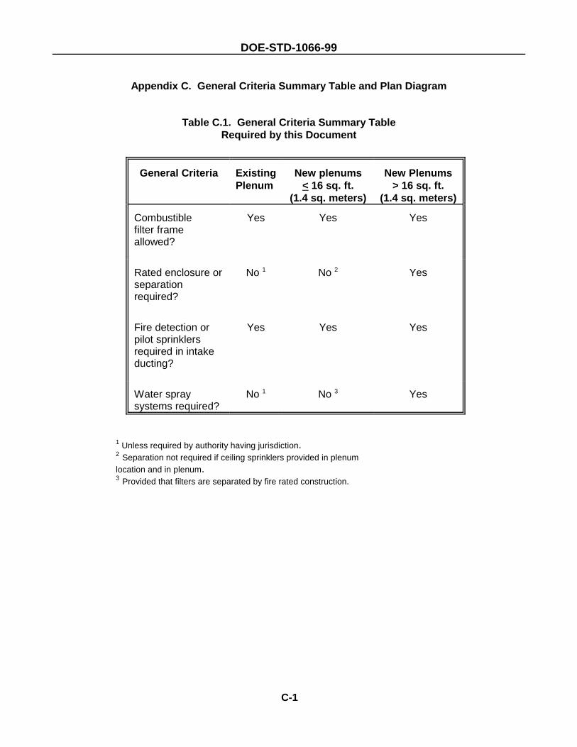
DOE-STD-1066-99
C-1
Appendix C. General Criteria Summary Table and Plan Diagram
Table C.1. General Criteria Summary TableRequired by this Document
General Criteria ExistingPlenum
New plenums< 16 sq. ft.
(1.4 sq. meters)
New Plenums> 16 sq. ft.
(1.4 sq. meters)
Combustiblefilter frameallowed?
Yes Yes Yes
Rated enclosure orseparationrequired?
No 1 No 2 Yes
Fire detection orpilot sprinklersrequired in intakeducting?
Yes Yes Yes
Water spraysystems required?
No 1 No 3 Yes
1 Unless required by authority having jurisdiction.2 Separation not required if ceiling sprinklers provided in plenumlocation and in plenum.3 Provided that filters are separated by fire rated construction.
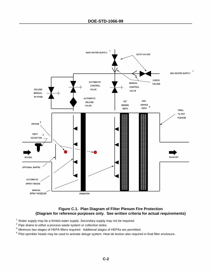
DOE-STD-1066-99
C-2
Figure C.1. Plan Diagram of Filter Plenum Fire Protection(Diagram for reference purposes only. See written criteria for actual requirements)
1 Water supply may be a limited water supply. Secondary supply may not be required.2 Pipe drains to either a process waste system or collection tanks.3 Minimum two stages of HEPA filters required. Additional stages of HEPAs are permitted.4 Pilot sprinkler heads may be used to activate deluge system. Heat de tection also required in final filter enclosure.
DOE-STD-1066-99
C-3
User Guidance for Selection, Use and Testing of Fire Protection Features for High Efficiency Air Filtration Systems
Filtration systems are designed to remove radioactive and other hazardous particulate from air handlingsystems before recirculation or discharge to the outside. A fire in a nuclear facility may result in anappreciable quantity of radioactive material becoming airborne in a form that is easily dispersed. Severaldesign measures are used to assure the survivability of the filtration system long enough for skilledfirefighters to attack and extinguish all but the most serious fires.
Table C.1 summarizes the general selection criteria for filters and filter enclosures. Combustible framesare allowed in all cases and in fact wood frames are commonly used. Although the wood frames mayhave a fire retardant treatment to delay ignition, they still burn once ignited. Other combustibles includethe organic binder that holds together the fiber filter media, sealants that attach the media to the frame,as well as accumulations of dust and particulate. Some filters may have noncombustible frames that aresubject to melting or distortion when heated. The glass fibers in the “paper” media curl and melt whenexposed to sufficient heat. Appendix B summarizes the effects of heat on the filter media. Althoughnuclear ventilation HEPA filters are qualified to assure a filter efficiency of at least 97% after exposureto air at 700 plus or minus 50 degrees F for 5 minutes, they may fail after longer exposures to lowertemperatures or more rapidly at higher temperatures. A typical fire produces temperatures more thandouble the temperature used in the qualification test.
The recommended arrangement for fire protection systems protecting HEPA filters is illustrated in FigureC.1. There are two separate water-based fire suppression systems. One is designed to protect the filtersfrom fire and the other to extinguish a fire that has reached the filters. The first system is an automaticdeluge spray system located in the plenum upstream of the filters and separated from the filters by ademister. The second is a manual deluge spray system directed at the first stage of filters. Theautomatic system is usually a deluge sprinkler system designed to meet the requirements of NFPAStandard 13. The manual system is usually a fixed water spray system designed in accordance withNFPA Standard 15. However, the reverse may be suitable in certain circumstances, provided that theperformance parameters are met. The term "deluge spray system" is used throughout this standard toprovide flexibility for the cognizant fire protection engineer to select the appropriate system.
Operation of the automatic deluge spray system is initiated by heat detectors located in the ducting. Thedetection system opens a deluge valve, allowing water flow to the nozzles. The spray nozzles are eitheropen sprinkler heads from which the fusible link has been removed or special purpose nozzles designedto produce a particular pattern. The automatic system is also equipped with a locked bypass valve thatcan be manually opened if the detection system or the deluge valve fail to operate. The purpose of theautomatic system is to cool the air stream so that the filters can continue to function during a fire in thefacility. The demister is intended to protect the filters from water damage. Closed head pilot sprinklersare sometimes used in place of an electrically operated heat detection system to open the deluge valveto the nozzles. In this case, the pilot sprinklers serve only as temperature sensors and do not spraywater.
Wetting is a particular problem for filters. Unlike qualification tests for some other fire resistant materials,the test standards used to qualify HEPA filter media do not require multiple wettings. In fact, the mediais permitted to lose up to 50% of its strength after a single 15 minute soaking period. There is norequirement for the media to return to full strength after drying and no limitation on further reduction instrength after subsequent soakings. Testing of both new and used filters verifies that they do lose
DOE-STD-1066-99
C-4
strength after thorough soaking and that subsequent soakings may produce further incrementalreductions in strength. As illustrated in Figure C.1, a high efficiency demister is installed downstream ofthe automatic deluge spray system to prevent water from soaking the filters. Section 14.8.2 of thisstandard provides efficiency criteria for the demister.
Fires produce smoke that can cause rapid clogging of filters. Since the automatic spray deluge systemfunctions much like the scrubbers that are used to clean smoke stack exhaust, there is an expectationthat the automatic system may also reduce smoke clogging. However, the nozzles are not optimized forsmoke reduction. In limited research with spray nozzles it was found that smoke clogging was reducedin some cases but increased in others. Therefore, premature manual activation of the spray delugesystem to knock down smoke is not recommended without further research to quantify results for specificarrangements and combustible contents. Procedures, such as shutting down or throttling back theblowers to prevent rupture of clogged filters during a fire, should be addressed in the authorization basisdocuments.
The second fire suppression system is a manual deluge spray system. This system is employed onlyif the filters begin to burn - it discharges water directly onto the first filter stage. Burning can not onlybreach the filters but may also release particulate that has accumulated on the filters over time. Facilitieswithout this manual system must rely on firefighters to attack HEPA filter fires with high pressure hosestreams. The manual deluge system is intended to avoid unnecessary exposure of firefighters who mustotherwise enter the hazardous environment within the plenum and also to assure a more gentleapplication of water, with the possibility that some filter stages may survive. The manual control valveis normally locked in the closed position and only accessible to firefighters. Fire Department trainingprograms should address operating procedures for these valves.
Periodic testing of the fire suppression systems is needed to assure that all components remainfunctional and to verify that debris has not blocked the nozzles, particularly those with a small orifice. Themost accurate method of testing would be to flow water periodically and observe the flow pattern fromthe nozzles. However, the sensitivity of the filters to water damage makes this approach unsuitable forthe manual deluge spray system and undesirable for the automatic deluge spray system in the absenceof experimental data to set facility specific guidelines. Alternative nozzle tests may use a gas such asair or carbon dioxide. If air is used, flow at the nozzle can be verified by deflection of a ribbon hangingin front of the nozzle. Carbon dioxide “fog” may be directly visible at the nozzle but requires a morerobust piping design. Where existing designs and limited future use of a facility make modificationsimpractical, then testing the automatic deluge spray system with water for up to one minute per quarteris not expected to be detrimental to downstream filters over a period of several years provided:
o it is verified that there is no gross water carryover through the demister, ando there is no significant increase in differential pressure across the first downstream HEPA filter during
or immediately after the test.
In any case, testing of both systems with water should be considered at the time of scheduledreplacement of filters.
DOE-STD-1066-99
4 Gewain, R., J. Shanley, P. DiNenno, J. Scheffey, B. Campbell. August 1991. Evaluation of Duct Opening Protectionin Two-hour Fire Walls and Partitions, Fire Technology, National Fire Protection Association, Quincy, Massachusetts. 5 Gewain, R. G., B. G. Campbell. J. H. Shanley Jr., J. L. Scheffey, May 1990. Protection of duct openings in two-hourfire resistant walls and partitions, ASHRAE JOURNAL, American Society of Heating, Refrigerating and Air-ConditioningEngineers, Inc., Atlanta.
D-1
Appendix D. Discussion on Evaluating Duct Openings When Penetrating 2-Hour Fire Walls
It is recognized by fire protection practices that fire dampers are not required in all cases when HVACducting penetrates fire rated construction. In NFPA 90A, Standard for the Installation of Air Conditioningand Ventilating Systems, 1989 Edition, Section 3-3.1, fire dampers are not required when ducts penetratefire rated barriers that have a resistance rating less than 2 hours.
However, NFPA 90A (Sections 3-3.1.1 and 3-4.1) requires 1 1/2-hour fire-rated dampers in ducts whichpenetrate fire barriers of 2 hours fire resistance or greater (but less than 3 hours). Section 3-4.2 of NFPA90A requires 3-hour fire-rated dampers in ducts which penetrate barriers having a fire resistance of 3hours or more.
The listing criteria for fire dampers, specified in UL 555, requires fire dampers to be tested in an assemblywith a standard time temperature fire exposure. The criteria for a damper passing the UL 555 testrequires that the damper remains closed during the duration of the fire test following a hose stream testwhere no flaming on the damper materials and no through openings that would allow flames to penetratethe fire wall occur.
In the UL 555 test, no duct work is connected to either side of the fire wall where the damper is testedbecause it is assumed that in a worst case situation the duct work will structurally fail, fall away from thedamper, and only the fire damper and housing will remain.
Using the passing criteria defined in UL 555, researchers4 5 have proposed equivalent protection of ductopenings with no fire damper installed where the duct remains intact near the wall opening creating abarrier to flames passing through the opening at the end of a 2-hour fire test.
The research has demonstrated that the most important factors in maintaining the integrity of the ductingthat prevents flaming through the duct opening after a one hour fire exposure is the quality of the ductconstruction and installation, a design which prevents gaps between the fire wall opening and the duct,and the design and protection of the duct hangers so that the ducts are supported throughout the fireperiod and hose stream test near the wall opening where the penetration occurs.
Full scale fire testing has demonstrated that specific size and design detailed for both rectangular andround ducts, installed per HVAC Duct Construction Standards, Metal and Flexible, will remain in placeover a 2-hour standard time temperature fire exposure.
The cited research addresses other methods to analyze duct penetrations in fire walls where fire dampersare excluded so that qualified engineers and designers can assess and qualify by engineering analysisother design scenarios for ducts not tested in the full scale tests performed by the researchers.
The research did not rely on trade-offs such as sprinkler protection as a method for qualifying the ducts.It was based on quantitative engineering equations and tools and fire test data. The research is notapplicable to ducts that contain combustible loading and did not address protection of openings in smokebarriers.

DOE-STD-1066-99
D-2
Users of the design criteria found in this Standard are encouraged to utilize the information obtained fromthe cited research for qualifying ducts for a 2-hour fire-rated exposure when a fire damper is not desirablein a confinement ventilation system. However, when qualifying duct configurations not fire tested by theresearch, users are cautioned to apply the research results only when applicable designs are supportedby engineering calculations performed by qualified engineers competent in the technology.
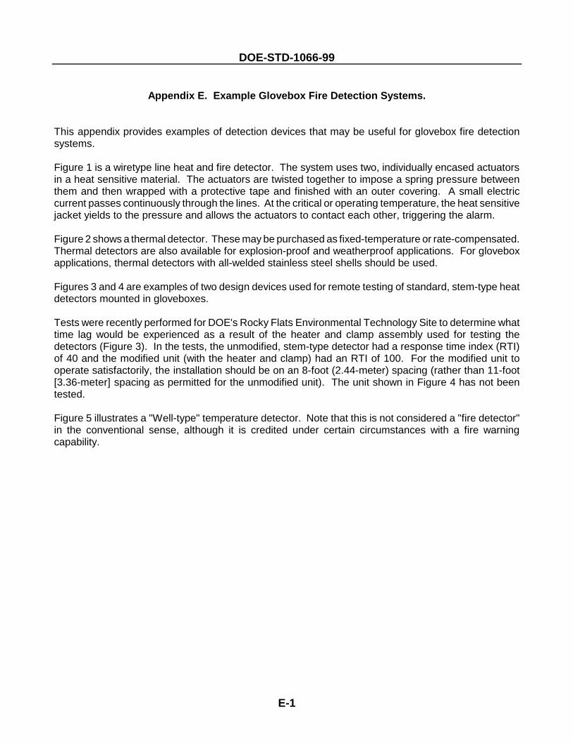
DOE-STD-1066-99
E-1
Appendix E. Example Glovebox Fire Detection Systems.
This appendix provides examples of detection devices that may be useful for glovebox fire detectionsystems.
Figure 1 is a wiretype line heat and fire detector. The system uses two, individually encased actuatorsin a heat sensitive material. The actuators are twisted together to impose a spring pressure betweenthem and then wrapped with a protective tape and finished with an outer covering. A small electriccurrent passes continuously through the lines. At the critical or operating temperature, the heat sensitivejacket yields to the pressure and allows the actuators to contact each other, triggering the alarm.
Figure 2 shows a thermal detector. These may be purchased as fixed-temperature or rate-compensated.Thermal detectors are also available for explosion-proof and weatherproof applications. For gloveboxapplications, thermal detectors with all-welded stainless steel shells should be used.
Figures 3 and 4 are examples of two design devices used for remote testing of standard, stem-type heatdetectors mounted in gloveboxes.
Tests were recently performed for DOE's Rocky Flats Environmental Technology Site to determine whattime lag would be experienced as a result of the heater and clamp assembly used for testing thedetectors (Figure 3). In the tests, the unmodified, stem-type detector had a response time index (RTI)of 40 and the modified unit (with the heater and clamp) had an RTI of 100. For the modified unit tooperate satisfactorily, the installation should be on an 8-foot (2.44-meter) spacing (rather than 11-foot[3.36-meter] spacing as permitted for the unmodified unit). The unit shown in Figure 4 has not beentested.
Figure 5 illustrates a "Well-type" temperature detector. Note that this is not considered a "fire detector"in the conventional sense, although it is credited under certain circumstances with a fire warningcapability.
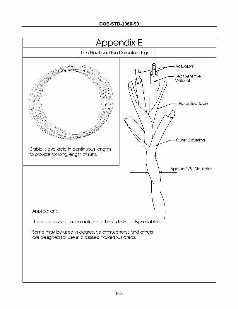
DOE-STD-1066-99
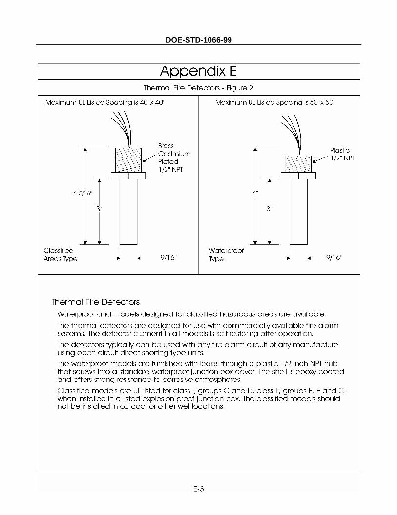
DOE-STD-1066-99
DOE-STD-1066-99
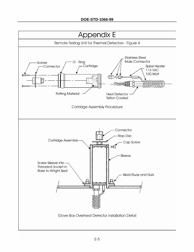
DOE-STD-1066-99
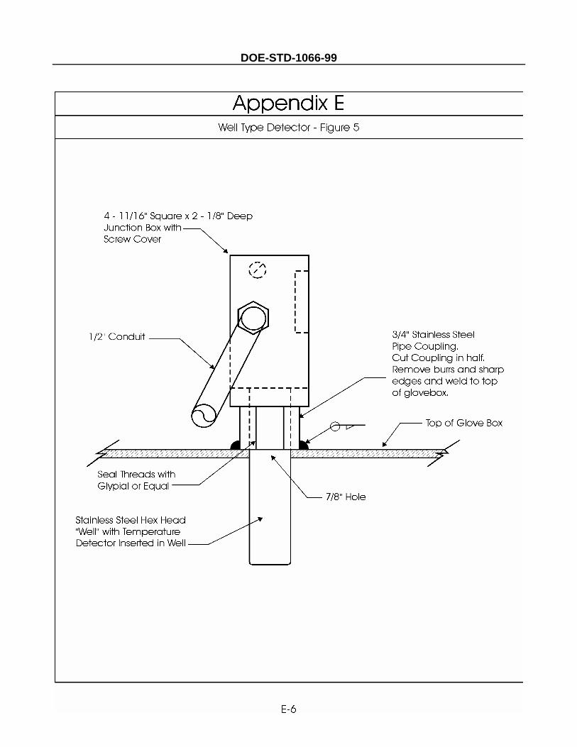
DOE-STD-1066-99
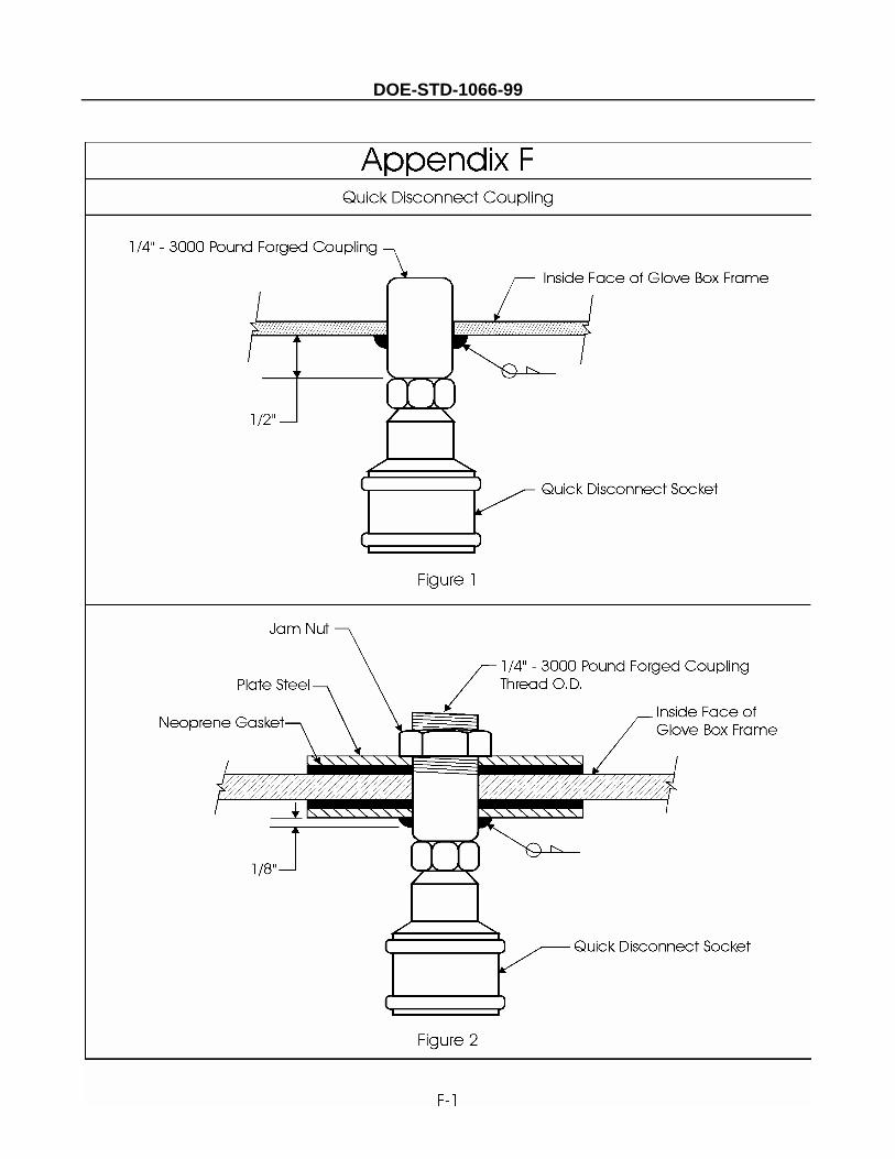
DOE-STD-1066-99

DOE-STD-1066-99
F-2
INTENTIONALLY BLANK
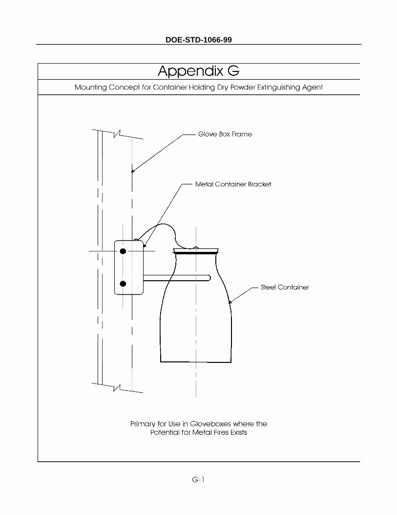
DOE-STD-1066-99
DOE-STD-1066-99
G-2
INTENTIONALLY BLANK
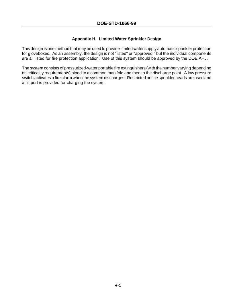
DOE-STD-1066-99
H-1
Appendix H. Limited Water Sprinkler Design
This design is one method that may be used to provide limited water supply automatic sprinkler protectionfor gloveboxes. As an assembly, the design is not "listed" or "approved," but the individual componentsare all listed for fire protection application. Use of this system should be approved by the DOE AHJ.
The system consists of pressurized-water portable fire extinguishers (with the number varying dependingon criticality requirements) piped to a common manifold and then to the discharge point. A low pressureswitch activates a fire alarm when the system discharges. Restricted orifice sprinkler heads are used anda fill port is provided for charging the system.
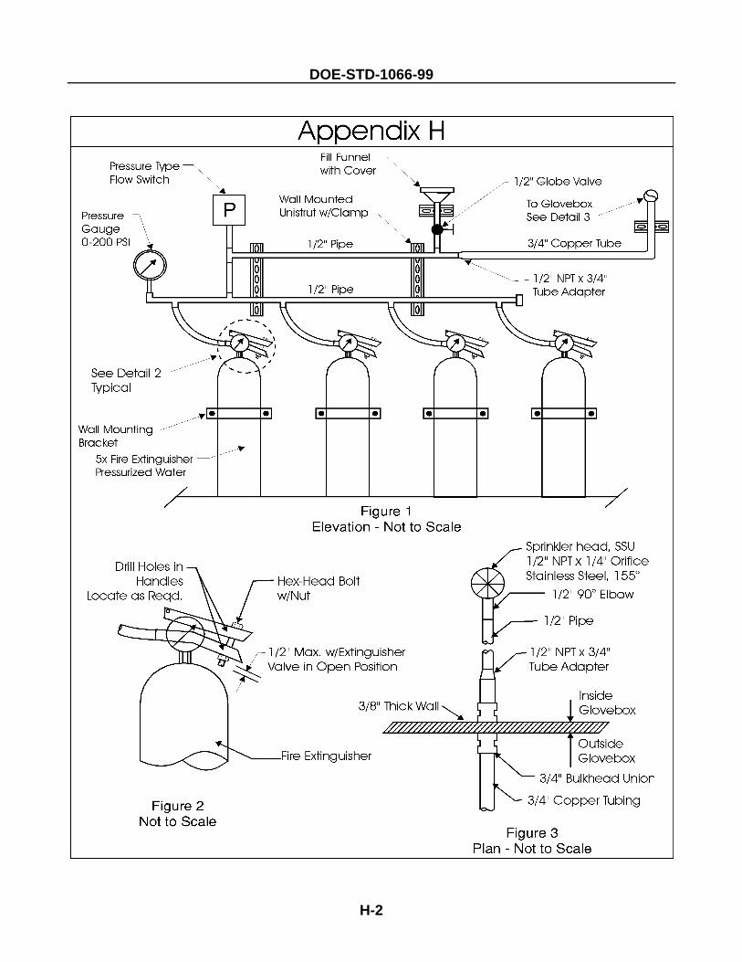
DOE-STD-1066-99
H-2
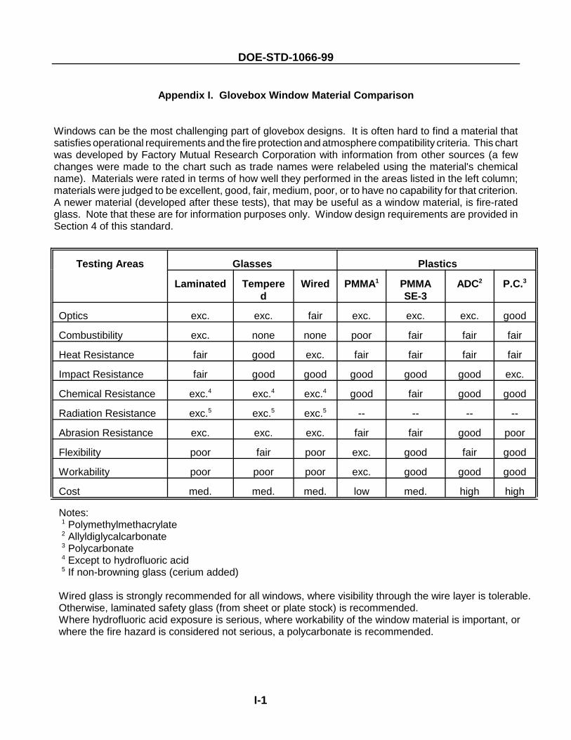
DOE-STD-1066-99
I-1
Appendix I. Glovebox Window Material Comparison
Windows can be the most challenging part of glovebox designs. It is often hard to find a material thatsatisfies operational requirements and the fire protection and atmosphere compatibility criteria. This chartwas developed by Factory Mutual Research Corporation with information from other sources (a fewchanges were made to the chart such as trade names were relabeled using the material's chemicalname). Materials were rated in terms of how well they performed in the areas listed in the left column;materials were judged to be excellent, good, fair, medium, poor, or to have no capability for that criterion.A newer material (developed after these tests), that may be useful as a window material, is fire-ratedglass. Note that these are for information purposes only. Window design requirements are provided inSection 4 of this standard.
Testing Areas Glasses Plastics
Laminated Tempered
Wired PMMA1 PMMASE-3
ADC2 P.C.3
Optics exc. exc. fair exc. exc. exc. good
Combustibility exc. none none poor fair fair fair
Heat Resistance fair good exc. fair fair fair fair
Impact Resistance fair good good good good good exc.
Chemical Resistance exc.4 exc.4 exc.4 good fair good good
Radiation Resistance exc.5 exc.5 exc.5 -- -- -- --
Abrasion Resistance exc. exc. exc. fair fair good poor
Flexibility poor fair poor exc. good fair good
Workability poor poor poor exc. good good good
Cost med. med. med. low med. high high
Notes: 1 Polymethylmethacrylate 2 Allyldiglycalcarbonate 3 Polycarbonate 4 Except to hydrofluoric acid 5 If non-browning glass (cerium added)
Wired glass is strongly recommended for all windows, where visibility through the wire layer is tolerable. Otherwise, laminated safety glass (from sheet or plate stock) is recommended.Where hydrofluoric acid exposure is serious, where workability of the window material is important, orwhere the fire hazard is considered not serious, a polycarbonate is recommended.
DOE-STD-1066-99
I-2
INTENTIONALLY BLANK

DOE-STD-1066-99
J-1
Appendix J. Glovebox Overpressure Protection Valves
These diagrams demonstrate the basic operating principles of dump/relief valves. These valves maybe useful in avoiding glovebox pressurization and maintaining exhaust ventilation. The Rocky FlatsEnvironmental Technology Site has used these valves in their glovebox lines for this purpose.
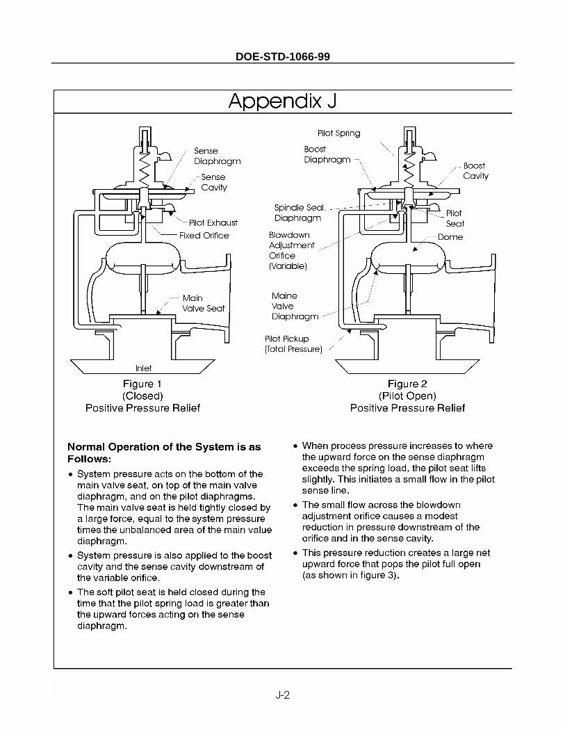
DOE-STD-1066-99
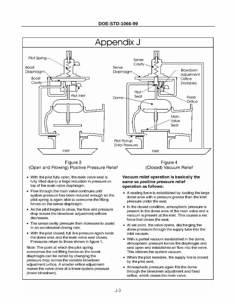
DOE-STD-1066-99

DOE-STD-1066-99
J-4
INTENTIONALLY BLANK
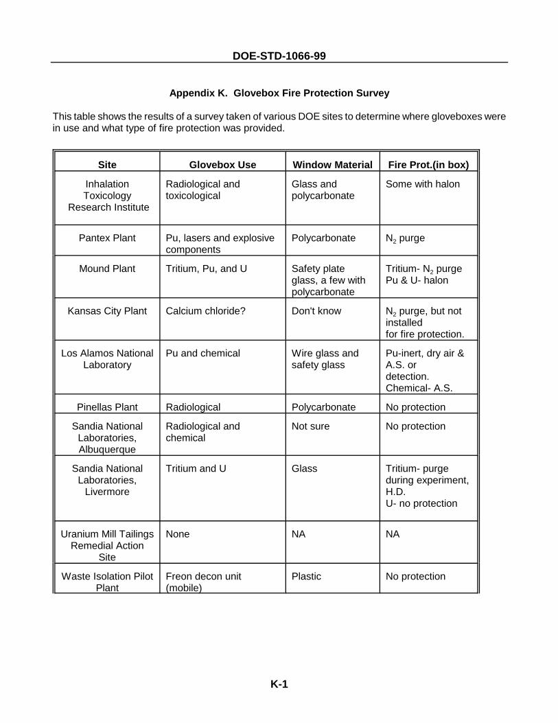
DOE-STD-1066-99
K-1
Appendix K. Glovebox Fire Protection Survey
This table shows the results of a survey taken of various DOE sites to determine where gloveboxes werein use and what type of fire protection was provided.
Site Glovebox Use Window Material Fire Prot.(in box)
InhalationToxicology
Research Institute
Radiological andtoxicological
Glass andpolycarbonate
Some with halon
Pantex Plant Pu, lasers and explosivecomponents
Polycarbonate N2 purge
Mound Plant Tritium, Pu, and U Safety plateglass, a few withpolycarbonate
Tritium- N2 purgePu & U- halon
Kansas City Plant Calcium chloride? Don't know N2 purge, but notinstalledfor fire protection.
Los Alamos NationalLaboratory
Pu and chemical Wire glass andsafety glass
Pu-inert, dry air &A.S. ordetection.Chemical- A.S.
Pinellas Plant Radiological Polycarbonate No protection
Sandia NationalLaboratories,Albuquerque
Radiological andchemical
Not sure No protection
Sandia NationalLaboratories,
Livermore
Tritium and U Glass Tritium- purgeduring experiment,H.D.U- no protection
Uranium Mill TailingsRemedial Action
Site
None NA NA
Waste Isolation PilotPlant
Freon decon unit(mobile)
Plastic No protection
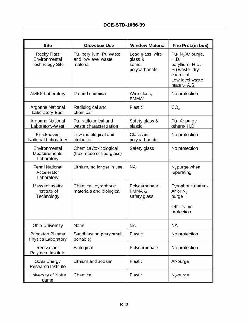
DOE-STD-1066-99
Site Glovebox Use Window Material Fire Prot.(in box)
K-2
Rocky FlatsEnvironmental
Technology Site
Pu, beryllium, Pu wasteand low-level wastematerial
Lead glass, wireglass &somepolycarbonate
Pu- N2/Ar purge,H.D.beryllium- H.D.Pu waste- drychemicalLow-level wastemater.- A.S.
AMES Laboratory Pu and chemical Wire glass,PMMA1
No protection
Argonne NationalLaboratory-East
Radiological andchemical
Plastic CO2
Argonne NationalLaboratory-West
Pu, radiological andwaste characterization
Safety glass &plastic
Pu- Ar purgeothers- H.D.
BrookhavenNational Laboratory
Low radiological andbiological
Glass andpolycarbonate
No protection
EnvironmentalMeasurements
Laboratory
Chemical/toxicological(box made of fiberglass)
Safety glass No protection
Fermi NationalAcceleratorLaboratory
Lithium, no longer in use. NA N2-purge when operating.
MassachusettsInstitute ofTechnology
Chemical, pyrophoricmaterials and biological
Polycarbonate,PMMA &safety glass
Pyrophoric mater.-Ar or N2purge
Others- noprotection
Ohio University None NA NA
Princeton PlasmaPhysics Laboratory
Sandblasting (very small,portable)
Plastic No protection
RensselaerPolytech. Institute
Biological Polycarbonate No protection
Solar EnergyResearch Institute
Lithium and sodium Plastic Ar-purge
University of Notredame
Chemical Plastic N2-purge
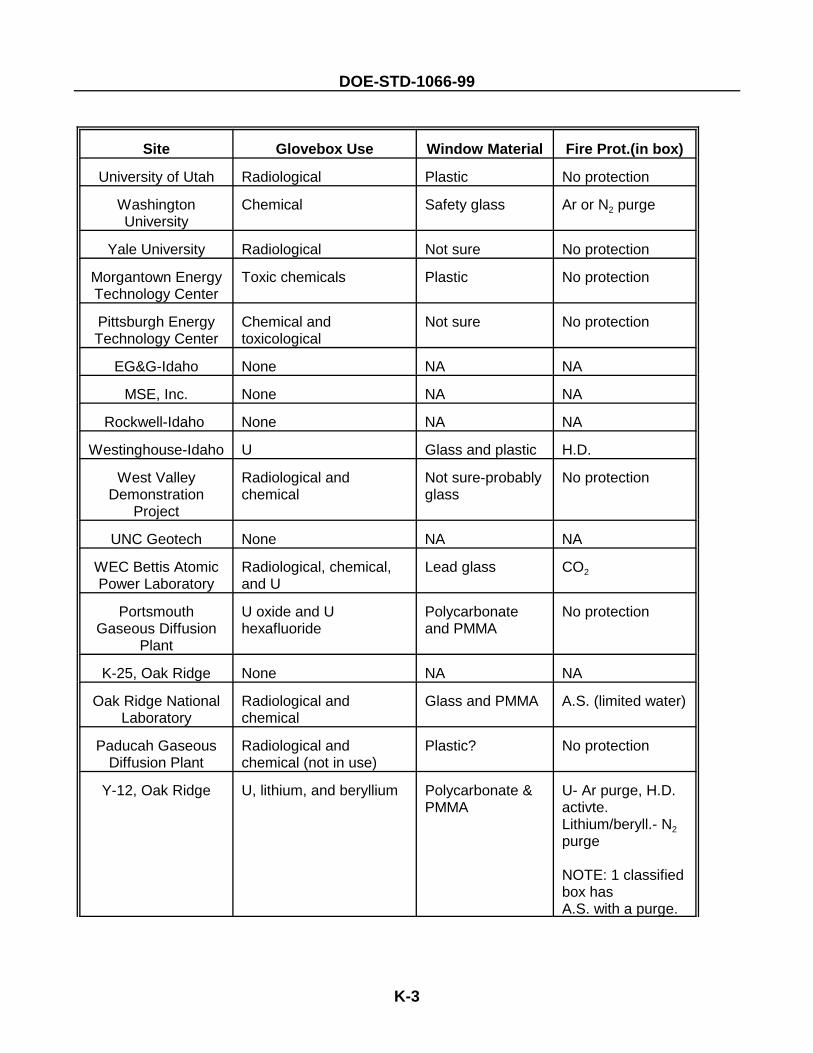
DOE-STD-1066-99
Site Glovebox Use Window Material Fire Prot.(in box)
K-3
University of Utah Radiological Plastic No protection
WashingtonUniversity
Chemical Safety glass Ar or N2 purge
Yale University Radiological Not sure No protection
Morgantown EnergyTechnology Center
Toxic chemicals Plastic No protection
Pittsburgh EnergyTechnology Center
Chemical andtoxicological
Not sure No protection
EG&G-Idaho None NA NA
MSE, Inc. None NA NA
Rockwell-Idaho None NA NA
Westinghouse-Idaho U Glass and plastic H.D.
West ValleyDemonstration
Project
Radiological andchemical
Not sure-probablyglass
No protection
UNC Geotech None NA NA
WEC Bettis AtomicPower Laboratory
Radiological, chemical,and U
Lead glass CO2
PortsmouthGaseous Diffusion
Plant
U oxide and Uhexafluoride
Polycarbonateand PMMA
No protection
K-25, Oak Ridge None NA NA
Oak Ridge NationalLaboratory
Radiological andchemical
Glass and PMMA A.S. (limited water)
Paducah GaseousDiffusion Plant
Radiological andchemical (not in use)
Plastic? No protection
Y-12, Oak Ridge U, lithium, and beryllium Polycarbonate &PMMA
U- Ar purge, H.D.activte.Lithium/beryll.- N2purge
NOTE: 1 classifiedbox hasA.S. with a purge.
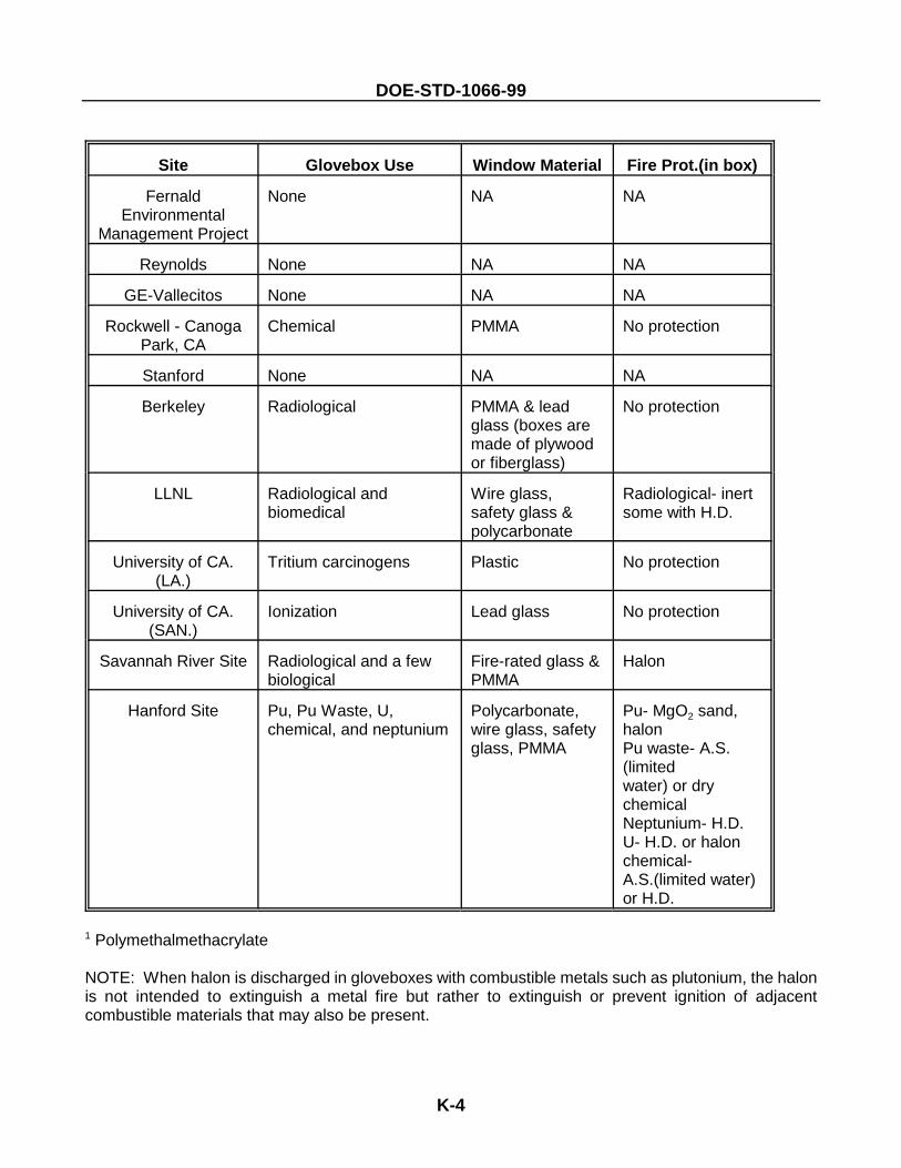
DOE-STD-1066-99
Site Glovebox Use Window Material Fire Prot.(in box)
K-4
FernaldEnvironmental
Management Project
None NA NA
Reynolds None NA NA
GE-Vallecitos None NA NA
Rockwell - CanogaPark, CA
Chemical PMMA No protection
Stanford None NA NA
Berkeley Radiological PMMA & leadglass (boxes aremade of plywoodor fiberglass)
No protection
LLNL Radiological andbiomedical
Wire glass, safety glass &polycarbonate
Radiological- inertsome with H.D.
University of CA.(LA.)
Tritium carcinogens Plastic No protection
University of CA.(SAN.)
Ionization Lead glass No protection
Savannah River Site Radiological and a few biological
Fire-rated glass &PMMA
Halon
Hanford Site Pu, Pu Waste, U,chemical, and neptunium
Polycarbonate,wire glass, safetyglass, PMMA
Pu- MgO2 sand,halonPu waste- A.S.(limited water) or drychemicalNeptunium- H.D.U- H.D. or halonchemical-A.S.(limited water)or H.D.
1 Polymethalmethacrylate
NOTE: When halon is discharged in gloveboxes with combustible metals such as plutonium, the halonis not intended to extinguish a metal fire but rather to extinguish or prevent ignition of adjacentcombustible materials that may also be present.
DOE-STD-1066-99
L-1
Appendix L. References
Filter Plenum References
Alvares, N., D. Beason, V. Bergman, J. Creighton, H. Ford, and A. Lipska. 1980. Fire ProtectionCountermeasures for Containment Ventilation, UCID-1878, Lawrence Livermore National Laboratory,Livermore, California.
American Society of Heating, Refrigeration and Air-Conditioning Engineers, Inc., 1988 ASHRAEHandbook Equipment, Atlanta, 1988.
American Society of Heating, Refrigeration and Air-Conditioning Engineers, Inc., 1991 ASHRAEHandbook Heating, Ventilation and Air-Conditioning Applications, Atlanta, 1991.
ANSI N304-1986, American National Standard for Nuclear Fuel Facilities - Facilities for ReprocessingFuel - Fire Protection, American National Standards Institute, Inc., 1986.
ASME N510, Testing of Nuclear Air Treatment Systems, The American Society of Mechanical Engineers,New York, 1989.
Bergman, W. G. Larson, R. Lopez, K. Williams, and C. Violet, High Efficiency Steel Filters for NuclearAir Cleaning, Proc. 21th DOE/NRC Nuclear Air Cleaning Conference, Boston, August 22-25, 1989.
Burchsted, C.A., J.E. Kahn and A.B. Fuller. 1976. Nuclear Air Cleaning Handbook, EDRA 76-21. OakRidge National Laboratory. Oak Ridge, Tennessee.
Campbell, B.G., Fire Protection for Filter Plenums at a Nuclear Facility, International Fire ProtectionEngineering Institute, May 30, 1989.
Carbaugh, E.H., Survey of HEPA Filter Applications and Experiences at Department of Energy Sites,Pacific Northwest Laboratory, Richland, November 1981.
Cartwright, D.R., C.M. Johnson, M.A. Thompson, Filter Plenum Fire Tests, The Dow Chemical CompanyRocky Flats Division, Golden, Colorado, September 3, 1970.
DOE Order 5480.7, Fire Protection, U.S. Department of Energy, Washington, D.C., Rev. November 1987.
DOE Order 5480.7A, Fire Protection, U.S. Department of Energy, Washington, D.C., Rev. Dec 1992.
DOE Order 6430.1A, General Design Criteria, U.S. Department of Energy, Washington, D.C., April 1989.
Domning, W.E., New Fire Protection Systems for Filter Plenums, 11th Proc. AEC Air CleaningConference, Richland, August 31-September 3, 1970.
Factory Mutual Research Corporation, Approval Guide 1991, Boston, 1991.Fluor Daniel, A Conceptual Study of Metal Fiber Filters for Nuclear Air Cleaning in the HWVP, U.S.Department of Energy, Richland, January 1991.Gaskill, J.R. and M.W. Magee, The HEPA-Filter Smoke Plugging Problem, Proc. 13th AEC Air CleaningConference, San Francisco, August 12-15, 1974.
DOE-STD-1066-99
L-2
Gewain, R. G., B. G. Campbell. J. H. Shanley Jr., J. L. Scheffey, May 1990. Protection of duct openingsin two-hour fire resistant walls and partitions, ASHRAE JOURNAL, American Society of Heating,Refrigerating and Air-Conditioning Engineers, Inc., Atlanta.
Gewain, R., J. Shanley, P. DiNenno, J. Scheffey, B. Campbell.August 1991. Evaluation of Duct Opening Protection in Two-hour Fire Walls and Partitions, FireTechnology, National Fire Protection Association, Quincy, Massachusetts.
Gregory, W.S., R.A. Martin, P.R. Smith, and D.E. Fenton, Response of HEPA Filters to SimulatedAccident Conditions, Proc. 17th DOE Air Cleaning Conference, Denver, August 2-5, 1982.
Hackney, S., Fire Testing of HEPA Filters Installed in Filter Housings, Proc. 17th DOE Air CleaningConference, Denver, August 2-5, 1982.
Hill, A.J., Fire Prevention and Protection in Hot Cells and Canyons, DP-1242, Savannah River Laboratory,Aiken, South Carolina, April 1977, pg 12.
Holmes, W.D., A Current Evaluation of Fire Loss Control Systems for Charcoal Media, Proc. 19thDOE/NRC Nuclear Air Cleaning Conference, Seattle, August 17-21, 1986.
Kovach, J.L., Review of Fire and Fire Control Methods for Nuclear Air Cleaning Systems, Proc. 19thDOE/NRC Nuclear Air Cleaning Conference, Seattle, August 17-21, 1986.
Lee, H.A., Final Report - Program for Fire Protection, Caves, Canyons, and Hot Cells, ARH-ST-104,Atlantic Richfield Hanford Company, Richland, August 1974.
Lee, H.A., Guide to Fire Protection in Caves, Canyons, and Hot Cells, ARH-3020, Atlantic RichfieldHanford Company, Richland, July 1974.
Mathewes, W., Conclusions from Fire Tests in Activated Carbon Filled Adsorbers, Proc. 19th DOE/NRCNuclear Air Cleaning Conference, Seattle, Washington, August 17-21, 1986.
NFPA 69, Explosion Prevention Systems, National Fire Protection Association, Vol 2, Boston, 1986.
NFPA 90A, Installation of Air Conditioning and Ventilation Systems, National Fire Protection Association,Vol 4, Boston, 1989.
NFPA 90B, Warm Air Heating and Air Conditioning Systems, National Fire Protection Association, Vol4, Boston, 1989.
NFPA 91, Blower and Exhaust Systems for Dust, Stock, and Vapor Removal or Conveying, National FireProtection Association, Vol 4, Boston, 1990.
NFPA 801, Facilities Handling Radioactive Materials, National Fire Protection Association, Vol 11,Boston, 1991.
NFPA 803, Fire Protection for Light Water Nuclear Power Plants, National Fire Protection Association,Vol 7, Boston, 1988.
DOE-STD-1066-99
L-3
Nuclear Standard NE F3-43, Quality Assurance Testing of HEPA Filters, U.S. Department of Energy, OakRidge, Tennessee, February 1990.
Nuclear Standard NE F3-45, Specifications for HEPA Filters Used By DOE Contractors, U.S. Departmentof Energy, Oak Ridge, Tennessee, October 1988.
Regulatory Guide 3.12, General Design Guide for Ventilation Systems of Plutonium and Fuel FabricationPlants, U.S. Atomic Energy Commission, Washington, D.C., 1973.
Regulatory Guide 3.32, General Design Guide for Ventilation Systems for Fuel Reprocessing Plants, U.S.Atomic Energy Commission, Washington, D.C., 1975.
Rockwell Hanford Operations Specification Number HWS 10278 Rev A000, Gaseous Effluent HEPAFilter System, In-Place Efficiency Testing of, Rockwell International, June 1981.
Rocky Flats Plant Standard No. SE-804, Standard for Deluge Fire Suppression Control System, RockwellInternational, September 1988.
Rocky Flats Plant Standard No. SE-805, Standard for GloveBox Overheat Detector Assembly (PushThrough Type), Rockwell International, August 11, 1989.
Rocky Flats Plant Standard No. SF-100, Fire Protection Standards, Rockwell International, Rev. October17, 1988.
Rüdinger, V., C.I. Ricketts, and J.G. Wilhelm, High-Strength High-Efficiency Particulate Air Filters forNuclear Applications, Nuclear Technology, Vol. 92, pp. 11-29 (October 1990).
Savornin, J., Means Used to Make Sure That the Confinement is Maintained in Case of Fire, Proc. 19thDOE/NRC Nuclear Air Cleaning Conference, Seattle, Washington, August 17-21, 1986.
Scowen, P.A., Still No Consensus On Containment Filter Venting, Nuclear Engineering International,February 1989.
UBC 1988, Uniform Building Code, International Conference of Building Officials, Whittier, California,1988.
Underwriters Laboratories, Inc., Building Materials Directory, Northbrook, Illinois, 1991.
Underwriters Laboratories, Inc., Fire Protection Equipment Directory, Northbrook, Illinois, 1991.
DOE-STD-1066-99
L-4
Glovebox References
C. A. Burchsted, J. E. Kahn, and A. B. Fuller. Nuclear Air Cleaning Handbook. ERDA 76-21. Oak Ridge,Tennessee. March 1976.
Factory Mutual Research Corporation. Glovebox Fire Safety. Norwood, Massachusetts. 1967.
J. D. Rapoza and F. E. Corning. Glovebox Fire Tests Using Pyrophoric Metal. Atomics International.Report No. AI-65-MEMO-209. October 1965.
National Fire Protection Association. NFPA 801, Recommended Fire Protection Practices for FacilitiesHandling Radioactive Materials. Quincy, Massachusetts. 1991 Edition.
Rocky Flats Plant Standard No. SE-802. Standard for Glovebox Overheat Detector Assembly (Self-Contained Testing). September 1990
Rocky Flats Plant Standard No. SE-805. Standard for Glovebox Overheat Detector Assembly (Push-Through Type). August 1989.
R. R. King Jr. Interim Report on the Glovebox Fire Control Studies. General Electric Company, (HW-67074). Richland, Washington. October 1960.
U.S. Atomic Energy Commission. Regulatory Guide 3.12. August 1973.
U.S. Department of Energy. DOE 6430.1A, General Design Criteria. April 1989.
W. E. Domning and R. W. Woodard. Glovebox Fire Tests. The Dow Chemical Company. Golden,Colorado. November 1970.
DOE-STD-1066-99
Concluding Material
Review Activity: Preparing Activity:DOE Field Offices DOE-EH-51
DP AL
EE CH
EH GO Project Number:EM ID FIRP-0001
NE NV
NN OR
ER RL
SF
SR
Fernald
National Laboratories
BNL
LLNL
LANL
NREL
PNL
Sandia
Area Offices
Amarillo Area Office
Kirtland Area Office
Princeton Area Office
Rocky Flats Area Office