Embed Size (px)
Citation preview

Juggler’s
Slide Rule
Instructions For Use
Advanced Rule
A2
By C Tombeur
SYSTEM
TOMBEUR

J
uggling is a physical skill involving the manipulation of objects for recreation, entertainment or
sport. It can be the manipulation of one object or many objects at the same time, using one or many hands, and has been in recorded history for 4000 years. The most recognizable form of juggling is toss juggling where props, usually balls or clubs and outnumbering the hands used, are thrown and caught so that at least one object is always in the air. Juggling is often described as an art, it can be performed anywhere, and everyone can learn to do it. Verylonggshsghsfghwordprintedinwhite

- 1 -
Contents
Introduction ....................................................................................... 2
Juggling Basics – Speed, Height & Weight ................................................... 3
Advanced Juggling Concepts ................................................................... 4
Hold Time ...................................................................................... 4
Throw Angle & Object Velocity............................................................ 6
Variables & Formulas ......................................................................... 7
Layout and Scales ................................................................................. 8
Juggling Calculations ............................................................................ 10
Pattern Speed, Height & Throw Weight ................................................. 10
Pattern Speed .............................................................................. 10
Speed & Height Calculations ............................................................ 11
Height & Weight/Hold Time Comparisons ......................................... 13
Patten Speed & Weight/Hold Time Comparisons .................................. 15
Relative Comparisons .................................................................... 16
Throw Angle & Object Velocity........................................................... 18
Throw Angle .............................................................................. 18
Object Velocity ........................................................................... 20
Basic Conventional Slide Rule Calculations ................................................. 22
Multiplication ............................................................................. 22
Division..................................................................................... 23
Squares and Square Roots ............................................................... 23
Reciprocals ................................................................................ 24
Sine’s ........................................................................................ 24
Example Problems .............................................................................. 25
Care of the Slide Rule .......................................................................... 32

- 2 -
Introduction
Juggler’s Slide Rules are simple, tactile calculating devices designed to help calculate and compare the complex mechanics behind common ball juggling patterns.
All Juggler’s Slide Rules make it possible to explore basic juggling concepts, such as pattern speed and throw characteristics, using specially designed SYSTEM TOMBEUR juggling scales. The enhanced juggling scales and layout of the Advanced Juggler’s Slide Rule offer great flexibility and ease of operation in performing these calculations and comparisons. They also accommodate more advanced juggling concepts for analysis of ‘real life’ juggling and pattern distortion, and calculation of additional pattern characteristics.
A further benefit of the Advanced Juggler's Slide Rule is making the standard A, B, C and D scales found on a Mannheim slide rule, supplemented by an S scale and a reciprocal CI scale, part of the overall Advanced scale layout. These scales allow normal slide rule calculations such as multiplication, division, squares, roots and some trigonometric calculations to be performed. The inclusion of these conventional scales also provides familiarity to all slide rule users.
Combining the juggling and conventional scales enables an exhaustive range of calculations and analysis to be performed on a single device.
This guide describes the mechanics of juggling and how to use the Advanced Juggler’s Side Rule to calculate and compare juggling characteristics.
It is assumed that the reader is familiar with the mechanics of using a slide rule. Brief instructions on basic, conventional slide rule calculations are included, but the reader is encouraged to refer to existing, comprehensive slide rule literature for further guidance.
No prior aptitude for juggling is needed, but it is recommended that the reader first becomes familiar with juggling concepts and terminology described in these instructions before using the slide rule, so that its full potential can be realised.

- 3 -
Juggling Basics – Speed, Height & Weight
Common juggling patterns usually consist of a number of balls all thrown to the same height, or a sequence of throws of different heights which lock into a repeating pattern. Throws are made from two hands alternately and regularly to a beat. The time between each beat in seconds is known as the Beat Time and determines the speed of the pattern. Pattern speed can also be expressed as number of throws per second which is the inverse of the Beat Time. The Weight of the throw of a ball, measured in beats, indicates when that ball will be next thrown in the pattern.
In patterns where all the balls in the pattern are consistently thrown the same, the weight of each throw is the number of balls in the pattern. Patterns like this that are based on an odd number of balls are known as ‘cascades’, whereas those based on an even number of balls are known as ‘fountains’.
For example, in a 3-ball cascade (Fig. 1), each hand throws a ball alternately once per beat and all the balls are thrown are the same. Since there are three balls, then each ball is next thrown three beats later, so the weight of each throw is called a ‘three’ (or ‘3’). Similarly, in a 4-ball fountain, all throws are the same so the weight of each throw is a ‘4’.
The pattern ‘534’, has four balls thrown with the repeating weights ‘5’ then ‘3’ then ‘4’. More complex patterns like this are usually named with the repeating part of the sequence, in this case ‘534’ from 534534534534…
In a theoretically neat pattern the hands trace small circles at a constant rate. When a ball is thrown by one hand another ball is caught by the other hand. Each hand is full for one beat and empty for one beat. The length of time a ball is held in the hand (between being caught and thrown) is called its Hold Time, and is measured in beats.
The weight of each throw determines the airtime in beats of the ball thrown as its weight minus one, since each ball is held in a hand for one beat. The flight of the ball is predictable according to the laws of projectile motion, and its maximum height can be determined from its airtime. Hence for different throw rates, heights for different weights can be calculated or compared. Similarly, throw rates for different weights and heights can be calculated or compared.
Fig. 1 : 3-ball cascade (beats in brackets show position of ball A).

- 4 -
Advanced Juggling Concepts
To use and appreciate the Advanced model slide rule it is necessary to expand upon certain aspects of basic juggling. ‘Hold Time’ describes this concept in greater detail and how it affects pattern speed and height. ‘Throw Angle & Object Velocity’ introduces these characteristics and how they can be determined. ‘Variables & Formulas’ provides a reference of equations and terms for calculations.
Hold Time
In theory the smoothest patterns are achieved when juggling with hold times of one beat. This is called the Base of the weight. In practice juggling with one beat hold times does not normally produce a smooth comfortable rhythm for the juggler. This is usually achieved with hold times of around 1.5 beats, depending on the pattern. When juggling with 2 hands throwing alternately to a regular beat, it is theoretically possible to have hold times of anywhere between 0 and 2 beats.
For example, Fig. 2a & b show a 3-ball cascade with hold times of approaching 0 beats, 1 beat and nearly 2 beats. Fig. 2a shows this from the jugglers perspective, Fig. 2b shows the position of the balls relative to the hands over time. In each case, each ball is still thrown every third beat and each hand throws every other beat. With a hold time of one beat each ball is in the air for two beats, and each hand is full for one beat and empty for one beat. In the case of zero beat hold time, each ball is thrown as soon as it is caught, so the hands are almost always empty and each ball is in the air for all three beats. When the pattern has a two beat hold time, each hand only throws a ball when it needs to catch its next ball. In this case the hands are almost always full and each ball is in the air for only one beat.
Fig. 2a : 3-ball cascade with 0, 1 & 2 beat hold times, from jugglers perspective (beats in brackets show position of ball A).
0 Beats 1 Beat 2 Beats

- 5 -
Hold time for a throw weight cannot go below zero beats or over 2 beats in regular patterns. Below zero hold time would mean the ball is thrown before it is caught, or it misses its beat and effectively becomes a different throw weight. Hold times over 2 beats would mean hands would either have to manipulate more than one ball at a time or throw off-beat, both situations making the pattern irregular.
The balls start and finish their flight at the same level, so if throws of the same weight and to the same beat are made with different hold times, then the maximum heights of the throws will be different because their airtime is different. Shorter hold times mean longer airtime, which mean higher throws. Longer hold times mean shorter airtime and therefore lower throws. So a weight can have a range of heights for the same beat time, thanks to the hold time. Conversely, weights thrown to a set height have a set range of possible beat speeds dependent on the hold time. Counter-intuitively, holding onto the balls for longer appears to produce a faster and more frantic pattern at the same beat because the airtime is less and the pattern lower.
Since the airtime of a ball is its weight minus its hold time, it can be seen that at the same beat, a weight 3 throw with zero hold time has the same airtime of 3 beats as a weight 4 throw with 1 beat hold time, and also a weight 5 throw with 2 beats hold time. Consequently their heights would all be the same. The table in Fig. 3 shows comparisons of airtimes for different weights and hold times.
0 Beats 1 Beat 2 Beats
Fig. 2b : 3-ball cascade with 0, 1 & 2 beat hold times, showing balls relative to hands over time (position of first throw of each ball marked).
Beat Left Right
6
1
2
3
4
5
B
C
A
Beat Left Right
1
2
3
4
5
6
A
B
C
Beat Left Right
5
6
1
2
3
4
A
B
C
3 4 5 6 7 8 9
0 3 4 5 6 7 8 9
1 2 3 4 5 6 7 8 Base
2 1 2 3 4 5 6 7
Throw Weight
Ho
ld T
ime
Fig. 3 : Airtimes (in beats) for given throw weights and hold times.

- 6 -
Jugglers can use different hold times in a pattern to create pattern distortions, which can then become new patterns in their own right. A simple example of this is an ‘over the top’ throw, thrown during a 3-ball cascade. The throw is still a weight 3 thrown to the same beat as the rest of the pattern, but the ball is thrown over the top of the other balls. To achieve this extra height, the hold time of the ball is reduced and hence its airtime increased.
A more extreme example of this is the 3-ball pattern ‘Arches’ (Fig. 4), which is a shape distortion of the 3-ball reverse cascade. A reverse cascade is simply a cascade where all the throws are made from the outside of the pattern towards the centre, the opposite direction to a normal cascade. In ‘Arches’ the first ball is thrown low, the second ball is thrown ‘over the top’ of the first, and the third ball is thrown ‘over the top’ of the second. This pattern then repeats and a steady beat maintained. Each of the 3 balls is thrown to a distinctly different ascending height, to great effect, by shortening the hold times.
Not only does hold time more accurately describe actual juggling, but hold times are a powerful tool for the juggler and they can easily be incorporated into calculations and comparisons of pattern speed, height and throw weight.
Throw Angle & Object Velocity
When an object is launched into the air, the laws of projectile motion dictate that due to the Earth’s gravity the vertical speed of the object will decrease to zero, and then the object will accelerate towards the Earth (Fig. 5). The rate of deceleration and acceleration due to gravity is a known fixed value at the Earth’s surface, regardless of the weight or size of the object. In a normal juggling environment, where the props are relatively small, slow moving and unaffected by wind, air resistance is negligible and can be ignored. Gravity has no effect on the horizontal speed of an object.
Usually when a juggling ball is thrown in a pattern its throw and catch heights are approximately the same, or offset equally from the centre of the circles described by the hands such that the effects cancel themselves out (Fig. 1). These conditions mean that the angle of trajectory of the throw of a juggling ball can be calculated simply
Fig. 4 : “Arches” (coloured beat numbers in brackets indicate ball position).

- 7 -
from the ball’s airtime (in seconds) and the horizontal distance it travels from hand to hand (throw width). It has been shown in previous sections that the airtime can easily be determined from the speed of the pattern or the throw height, and the weight and hold time of the throw. The throw width can be measured.
The maximum vertical velocity of a ball (when it leaves the hand and again when it is caught) can be calculated from just the maximum height it achieves, which can be either set or determined. Using the vertical velocity and the angle of trajectory the actual maximum object velocity can be calculated.
Different combinations of throw rate, weight, height, hold time, angle, velocity and throw width can be calculated and compared from different starting points. Formulas for calculations of throw angle and velocity are provided for reference in the following section.
Variables & Formulas
Fig. 5 shows the parabolic path of a ball thrown. The definitions of the variables used and juggling formulas are described below.
h = maximum height achieved (metres) Beat time :
d = throw width (metres)
t = airtime (seconds) Airtime :
θ = throw angle (degrees)
g = acceleration due to gravity (9.81 ms-1) Height :
v = maximum velocity (ms-1)
vy = maximum vertical velocity (ms-1) Throw angle :
n = throw weight
bt = beat time (seconds) :
f = throw rate (throws per second)
wb = hold time (beats) Velocity :
fb
1
)( bwnbt
8
2 gth
hgv y 2
d
gt
2tan
2
sin
yvv
Vertical Velocity
Fig. 5 : Flight path of a ball.

- 8 -
Layout and Scales
The single sided closed frame slide rule has 9 scales – two on each of the top and bottom front faces of the stock, and five on the front of the single sided slide. A cursor with single central hairline aids calculations and comparisons.
Six of the scales are standard logarithmic slide rule scales (A, B, C, D, S & CI) and 3
are custom juggling scales (X, n(wb) & ). The standard scales are printed in black with the exception of the red CI scale and green S scale. The SYSTEM TOMBEUR
juggling scales are printed in blue with the exception of the green scale (consistent with S, the other angle scale).
The scales are described here from top to bottom.
Above the slide on the front face:
‘X’ scale, blue, 2(1.097)-10(0.97) and 11(1.97)-11(1), also labelled ‘n(wb)’. Logarithmic throw weight juggling scale for weights (n) 2 to 11. Weights 2 and 11 share the same graduation mark. Weights are marked at the base of the weight where hold time (wb) is 1 beat. Graduations for hold times from (2) to (0) beats are marked between the weights. Note that the weight/hold ranges overlap and share the same graduations, and hold times (2) to (0) run in reverse direction to the weights (2 to 11).
‘A’ scale, black, 1-100, also labelled ‘h, d x 10-2m’. Standard slide rule logarithmic A scale, also used to represent throw height (h) in centimetres or metres, and throw width (d) in centimetres.
Slide:
‘B’ scale, black, 1-100. Standard slide rule logarithmic B scale.
‘S’ scale, green, 5°44’-90°. Standard slide rule logarithmic Sine scale, referenced against the C scale.
‘CI’ scale, red, 10-1, also labelled ‘bs-1’. Standard slide rule logarithmic reciprocal scale, also used to represent throw rate in beats per second.
‘n(wb)’ scale, blue, 2(1)-11(1). Logarithmic throw weight juggling scale for weights (n) 2 to 11, similar to the ‘X’ scale. The scale uses the tick marks/graduations of the lower ‘C’ scale. Weights are marked at the base of the weight where hold time (wb) is 1 beat. Graduations for hold times from (2) to (0) beats are marked between the weights. Note that the weight (hold) ranges overlap and share the same graduations, and hold times (2) to (0) run in reverse direction to the weights (2 to 10).

- 9 -
‘C’ scale, black, 1-10, also labelled ‘t, bt x10-1s’. Standard slide rule logarithmic C scale, also used to represent airtime (t) and beat time (bt) in seconds x10-1.
Below the slide on the front face:
‘D’ scale, black, 1-10, also labelled ‘v’. Standard slide rule logarithmic D scale, also used to represent maximum velocity (v).
‘ ’ scale, 2 ranges, upper 89°53’-78°30’, lower 78°30’-2°50’.
Logarithmic juggling scale to represent throw angle to the horizontal ( .
In general, the scales only have value labels at the major tick mark divisions. In most cases the major divisions are then graduated with tick marks to two further levels, allowing 3 significant figures to be accurately represented in calculations. However, due to the logarithmic nature of the scales, graduations are not necessarily consistent within or across the scales. With practice the user will quickly become familiar with the scale layouts and graduations, but care should always be taken that values are correctly set and read.
Decimal points and trailing zeros are ignored when performing calculations. For example 1.25 x 250 and 12.5 x 25 are calculated in the same way as 125 x 25. The correct magnitude is determined once the result has been obtained.
The left and right-hand end value marks of the conventional scales are used as indexes in calculations. The most commonly used are those on the slide, they are the aligned “1” values (B, CI & C scales) at the left-hand end and aligned “100”, “1” and “10” values (B, CI & C scales respectively) at the right-hand end. The indexes on the stock are the aligned “1” values (A & D scales) at the left-hand end and “100” and “10” values (A & D scales respectively) at the right-hand end.
The scales feature a number of gauge marks to assist in calculations:
(3142) on A, B, C & D scales.
C (1128) on C scale.
C1 (3568) on C scale.
vy (4429) on C scale.
g (981) on C scale.
Variables, formulas, summary instructions and methods for determining magnitudes are printed on the back of the stock, with a blind stamped production date (MM & YYYY) on the left and a blind stamped serial number (nnn) on the right.

- 10 -
Juggling Calculations
This section describes how to perform juggling calculations and comparisons using the Advanced SYSTEM TOMBEUR slide rule, with a possible accuracy of up to 3 significant figures. When practicing, learning new techniques or developing new patterns, this degree of accuracy is unnecessary for a juggler, who juggles largely by feel, intuition and experience. However, when using these calculations to describe what is happening in juggling patterns, this level of accuracy can be insightful and also highlight how small changes can have a large impact on a pattern, demonstrating what a precise art juggling can be when performed well.
The section is divided into two logical parts – ‘Pattern Speed, Height & Throw Weight’ and ‘Throw Angle & Velocity’. In each part the operations required to determine and compare values are described, with examples given throughout.
Pattern Speed, Height & Throw Weight
Pattern speed, height and throw weight are fundamentally interconnected. In order to understand the relationship of the variables and their use in calculations, this section has been further divided into topics. However, the reader is encouraged to study and refer to these topics within the context of this section as a whole.
Pattern Speed
Pattern speed can either be represented on the C scale or the CI scale. The C scale represents the beat time in seconds. The CI scale, being the reciprocal of the C scale, represents beats (and therefore throws) per second.
Usually the speed of a pattern is such that the beat time is between 0.1 and 1 second and this is represented on the C scale by using the values 1 to 10. Beats or throws per second can be directly read on the CI scale against beat time values on the C scale, or vice versa. The cursor hairline can be used to determine equivalents with greater accuracy if required.
Example 1 : What is the beat time equivalent to throwing 6 balls per second?
First ensure that all the scales are aligned under one another at the left-hand index end. Set the cursor hairline to the “6” tick mark on the CI scale, representing 6 throws per second. Read off the corresponding beat time of 0.167 seconds under the hairline on the C scale (Fig. 6).
The C and CI scales can also represent beat times of 1 to 10 seconds (1 to 0.1 throws per second) or higher, but the resulting calculations must be factored accordingly.
1 9 8 7 6 5
1 21.1 1.91.2 1.3 1.4 1.5 1.6 1.7 1.8
3 (1)(1.5)(2)2 (1) (0.5) (0) (2)
8 976 10
n (wb)
S
Ct, bt x10-1s
CIbs-1
C Fig. 6
CI
C

- 11 -
Speed & Height Calculations
Calculations involving pattern speed, height, throw weights and hold times primarily use the X (weight/hold), A (height), CI (throw rate), and C (beat time) scales.
The X (throw weight) scale is labelled with throw weights (2 to 11) at the base of the weight, that is where the hold time is one beat. For example weight 3 hold 1 beat is labelled as 3(1). Hold times from 0 beats to 2 beats can be found by using the graduations on the scale between the labelled weights. Arrows from each weight base to the left and right indicate increasing and decreasing hold times to their maximum of 2 beats and minimum of 0 beats for the weight. Care should be taken since whereas the weights increase from left to right, the hold times increase from right to left. Also the weight hold ranges overlap, for example 3(0) = 4(1) = 5(2) or 3(0.5) = 4(1.5).
To determine the maximum height achieved by a ball thrown at a certain weight and hold time, and at a particular beat time or throw rate in seconds, first find the weight and hold time value on the X scale and set the cursor hairline to it. Next set either the left or right-hand index of the slide to the cursor hairline. Find the pattern speed value on either the C or CI scale, and set the cursor hairline to it. If the pattern speed value is such that its position on the slide is physically outside of the scale ranges on the stock, use the other index end of the slide. Read off the height on the A scale underneath the cursor hairline.
Magnitudes for height are determined as follows for beat times of 0.1 to 1 second (10 to 1 throws per second):
For throw weights up to 10, and when the slide protrudes from the stock to the right, then the height is in centimetres.
For throw weights up to 10, and when the slide protrudes from the stock to the left, then the height is in metres.
For throw weights 11 and above, and when the slide protrudes from the stock to the right, then the height is in metres.
For throw weights 11 and above, and when the slide protrudes from the stock to the left, then the height is in metres times 100.
If the beat time is in the range 1 to 10 seconds, the same rules are used and the resulting height is factored again by 100 (since height is proportional to the square of the time).
Once an index end of the slide is set to a weight/hold time value on the throw weight (X) scale, corresponding heights can be read for all pattern speed values on

- 12 -
the C or CI scales that are in the A scale range. Setting the other index end of the slide to the weight/hold time enables heights to be read against pattern speeds that were previously off the scale.
Similarly, pattern speeds can be read on the C or CI scales for specific heights on the A scale, and setting the correct index end on the slide to the weight/hold time mark on the X scale will ensure that values can always be read.
Example 2 : To what respective heights would the balls in a theoretically neat 5-ball cascade (with hold times of 1 beat) have to be thrown to achieve a rhythm of 3 balls per second, and then a throwing beat of 0.5 seconds?
Set the cursor hairline over the “5(1)” weight tick mark on the X scale representing a weight 5 throw with a hold time of 1 beat. Now set the right-hand index end of the slide under the cursor hairline. Next position the cursor hairline over the “3” tick mark on the CI scale on the slide to indicate 3 throws per second. Using the hairline the corresponding throw height of 2.18 metres can now be read off on the A scale on the bottom of the upper stock face. Simply repositioning the cursor hairline over the “5” tick mark on the C scale gives the alternative throw height of 4.91 metres on the A scale for a beat time of 0.5 seconds (Fig. 7).
Example 3 : What throwing beat or rhythm is needed to sustain a 6-ball fountain when the balls are juggled/thrown to a height of 3 metres using a comfortable 1.5 beat hold time?
Set the cursor hairline over the “6(1.5)” weight tick mark on the X scale representing a weight 6 throw with a hold time of 1.5 beats. Set the right-hand index end of the slide under the cursor hairline. This time place the cursor hairline over the “3” tick mark on the A scale to indicate 3 metres. The corresponding throwing beat or rhythm of 0.348 seconds is under the hairline on C scale, or 2.88 throws per second on the CI scale (Fig. 8).
1 2 3 4 5 76 8 9 10 20
(1.5)
(0.5)
3 (1) 5 (1)(1.5)(2) (0.5) (0)11 (1)
2 (1) 4 (1)(0.5) (1.5)(0) (2)
(2) (0.5)
(0) (1.5)(2)(0)(2)
X n (wb)
Ah, d x10-2m π
5 4 3 2 11.11.9 1.21.31.41.51.61.71.8
108 94 65 72 3
4 5 76 8 9 10 20 30 40 50 60 70 80 90 100
(1.5)(0.5)
3 (1) 5 (1)(0.5) (0) 7 (1) 9 (1) 114 (1)(1.5)(2)
(2) (0.5) (0)(0) 6 (1)(1.5)(2) (0.5) (0) 8 (1)(2) (0) 10 (1)(2) (0)
(1.5)(2) (0) (2) (0) (2)
90706050403020
π vygC1 Fig. 7
2 3 4 5 76 8 9 10 20 30
(1.5)
(0.5)
3 (1) 5 (1)(1.5)(2) (0.5) (0)11 (1)
2 (1) 4 (1)(0.5) (1.5)(0) (2)
(2) (0.5) (0)
(0) 6 (1)(1.5)(2)(0)
(2)
π
4 3 2 11.11.9 1.21.31.41.51.61.71.8
108 94 65 73
5 76 8 9 10 20 30 40 50 60 70 80 90 100
(1.5)(0.5)
5 (1)(0.5) (0) 7 (1) 9 (1) 114 (1)(1.5)
(2) (0.5) (0)(0) 6 (1)(1.5)(2) (0.5) (0) 8 (1)(2) (0) 10 (1)(2) (0)
(1.5)(2) (0) (2) (0) (2)
90706050403020
π vygC1 Fig. 8
X
A
CI
C
X
A
CI
C

- 13 -
Height & Weight/Hold Time Comparisons
The weight/hold time scale on the slide, n(wb), is the same scale as the weight/hold time scale (X) at the top of the upper face of the stock. However, the weights have been positioned to make use of the graduations on the C scale, and the values run from 2(1) to 11(1). Care should be taken when using the n(wb) scale on the slide, that the n(wb) scale value labels and corresponding C scale graduations are used correctly, and the inherent C scale values are ignored.
When a height has either been set or determined for a particular weight and hold time, it is very easy to quickly find all heights for all hold times (0 to 2 beats) for that weight/hold time and pattern speed by using the n(wb) scale on the slide.
Position the cursor hairline over the starting height on the A scale. Move the slide so that the weight/hold marker on the n(wb) scale on the slide for the initial weight/hold time is underneath the cursor hairline. Heights can then be read on the A scale against all values of hold time on the n(wb) scale for the chosen weight, using the cursor to read across the scales. Further, for any height value on the A scale, any weight/hold time on the n(wb) scale can be set to it and heights read on the A scale against all weight/hold times on the n(wb) scale.
If values are out of range on the slide, use the cursor hairline to mark the index end of the slide and then align the other index end to the hairline. Values can now be read but may need to be factored as appropriate.
Example 4 : A juggler comfortably juggles a 4-ball fountain with a hold time of 1.5 beats to a height of 1.2 metres. To demonstrate the pattern at the same speed with lower hold times of 1 beat and 0.5 beats, what respective heights would the balls have to be thrown to?
Set the cursor hairline over the “1.2” tick mark on the A scale representing the height in metres. Move the slide so that the “4(1.5)” weight tick mark on the n(wb) scale is underneath the hairline, setting the weight of 4 with the initial 1.5 beat hold time. Now position the hairline over the “4(1)” weight tick mark on the n(wb) scale and read off the corresponding height of 1.73 metres underneath the hairline on the A scale for a 1 beat hold time. Next move the cursor hairline over the “4(0.5)” weight tick mark on the n(wb) scale for a 0.5 beat hold time, and read off the corresponding height underneath the hairline on the A scale of 2.35 metres (Fig 9).
1 2 3 4 5
3(1.5)(2)11 (1)
2 (1) (0.5) (0)(0)(2)
X n (wb)
Ah, d x10-2m π
5 4 3 2
4 52 31.91.8
4 5 76 8 9 10 20
(1.5)(0.5)
3 (1) 5 (1)(0.5) (0)4 (1)(1.5)(0) (2)
(2) (0.5) (0)(0) 6 (1)(1.5)(2)
3020
π vy
π
C1 Fig. 9
A
n(wb)
- 14 -
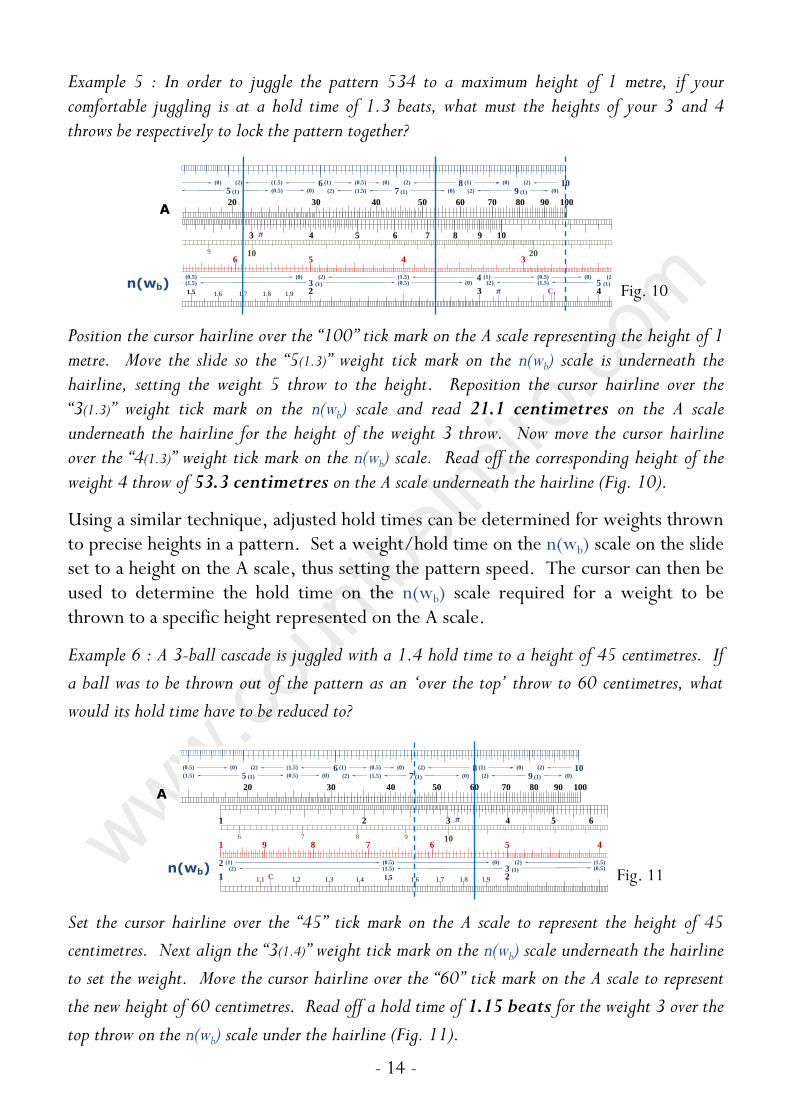
Example 5 : In order to juggle the pattern 534 to a maximum height of 1 metre, if your comfortable juggling is at a hold time of 1.3 beats, what must the heights of your 3 and 4 throws be respectively to lock the pattern together?
Position the cursor hairline over the “100” tick mark on the A scale representing the height of 1 metre. Move the slide so the “5(1.3)” weight tick mark on the n(wb) scale is underneath the hairline, setting the weight 5 throw to the height. Reposition the cursor hairline over the “3(1.3)” weight tick mark on the n(wb) scale and read 21.1 centimetres on the A scale underneath the hairline for the height of the weight 3 throw. Now move the cursor hairline over the “4(1.3)” weight tick mark on the n(wb) scale. Read off the corresponding height of the weight 4 throw of 53.3 centimetres on the A scale underneath the hairline (Fig. 10).
Using a similar technique, adjusted hold times can be determined for weights thrown to precise heights in a pattern. Set a weight/hold time on the n(wb) scale on the slide set to a height on the A scale, thus setting the pattern speed. The cursor can then be used to determine the hold time on the n(wb) scale required for a weight to be thrown to a specific height represented on the A scale.
Example 6 : A 3-ball cascade is juggled with a 1.4 hold time to a height of 45 centimetres. If
a ball was to be thrown out of the pattern as an ‘over the top’ throw to 60 centimetres, what
would its hold time have to be reduced to?
Set the cursor hairline over the “45” tick mark on the A scale to represent the height of 45
centimetres. Next align the “3(1.4)” weight tick mark on the n(wb) scale underneath the hairline
to set the weight. Move the cursor hairline over the “60” tick mark on the A scale to represent
the new height of 60 centimetres. Read off a hold time of 1.15 beats for the weight 3 over the
top throw on the n(wb) scale under the hairline (Fig. 11).
20 30 40 50 60 70 80 90 100
(1.5)
(0.5)
5 (1) 7 (1) 9 (1)(0.5) (0)
(0) 6 (1)(1.5)(2) (0.5) (0) 8 (1)(2) (0) 10(2)
(1.5)(2) (0) (2) (0)
1 9 8 7 6 5 4
1 21.1 1.91.2 1.3 1.4 1.5 1.6 1.7 1.8
1 2 3 4 5 6
3 (1)(1.5)(2) (0.5)2 (1) (0.5) (1.5)(0) (2)
8 976 10
n (wb)
S
Ct, bt x10-1s
B
CIbs-1
π
C Fig. 11
A
n(wb)
20 30 40 50 60 70 80 90 100
5 (1) 7 (1) 9 (1)(0.5) (0)
(0) 6 (1)(1.5)(2) (0.5) (0) 8 (1)(2) (0) 10(2)
(1.5)(2) (0) (2) (0)
6 5 4 3
42 31.91.5 1.6 1.7 1.8
3 4 5 76 8 9 10
(1.5)(0.5)
3 (1) 5 (1)(1.5) (0.5) (0)4 (1)(0.5) (1.5)(0) (2)
(2)(0) (2)
209 10
π
π
C1 Fig. 10
A
n(wb)

- 15 -
Patten Speed & Weight/Hold Time Comparisons
When a pattern speed has either been set or determined for a particular weight and hold time, it is very easy to quickly find all the pattern speeds for all the hold times (0 to 2 beats) for that weight and height by using the X scale (weight/hold time).
To do this the C or CI scales are used for pattern speed, however due nature of the calculation their functions are reversed. The C scale is used to represent the pattern speed in throws per second, and the CI scale is used to represent the beat time in seconds. Care should be taken that the correct scale is used. It is useful to remember that longer hold times produce slower patterns and shorter hold times produce faster patterns to the same height.
Position the cursor hairline over the initial weight/hold time value on the X scale and move the slide so that the initial pattern speed on either the CI or C is underneath the cursor hairline. Pattern speeds can then be read on either the CI scale (beat time) or C scale (throws per second) against all values of the hold time on the X scale for the chosen weight, using the cursor to read across the scales. In fact, any pattern speed can be set to any weight/hold time on the X scale and the pattern speeds read off the C or CI scales against all the weight/hold times on the X scale.
If values are out of range on the slide, use the cursor hairline to mark the index end of the slide and then realign the other index end to the hairline. Values can now be read off but may need to be factored as appropriate.
Example 7 : The height of a 5-ball cascade with a hold time of 0.5 beats and thrown at 2 beats per second is 6.21 metres. What would the rhythm need to be to maintain this height with a 4-ball fountain at 1 beat hold time, and an 11-ball cascade with 1.5 beat hold time?
Set the cursor hairline over the “5(0.5)” tick mark on the X scale, representing the reference weight and hold time. Align the pattern speed of 2 throws per second to the weight/hold time by moving the slide so the “2” tick mark on the C scale is underneath the hairline. To find the pattern speed of the 4-ball fountain with hold times of 1 beat, reposition the cursor hairline over the “4(1)” tick mark on the X scale. Read off the throw rate of 1.33 balls per second on the C scale under the hairline (Fig. 12a).
1 2 3 4 5 76 8 9 10 20 30
(1.5)
(0.5)
3 (1) 5 (1)(1.5)(2) (0.5) (0)11 (1)
2 (1) 4 (1)(0.5) (1.5)(0) (2)
(2) (0.5) (0)
(0) 6 (1)(1.5)(2)(0)
(2)(2)
π
1 9 8 7 6 5
1 21.1 1.91.2 1.3 1.4 1.5 1.6 1.7 1.8
1 2 3 4 5
3 (1)(1.5)(2)2 (1) (0.5) (0) (2)
8 976 10
n (wb)
S
Ct, bt x10-1s
B
CIbs-1
π
C
Fig. 12a
X
C

- 16 -
The cursor should then be repositioned over the weight/hold time mark on the X scale for the 11-ball cascade in order to read its pattern speed. However the weight 11 tick marks are not within the range of the scales on the slide, so the slide must be re-positioned first. Set the cursor hairline over the left-hand index end of the slide and then move the slide so the right-hand index end is underneath the hairline. Now position the cursor hairline over the “11(1.5)” tick mark on the X scale representing the weight 11 throws with 1.5 beat hold time. Underneath the hairline on the C scale, read off the pattern speed of 4.22 throws per second (Fig. 12b).
Relative Comparisons
Multiples of beat time or throw height for different throw weights and hold times can easily be determined using the n(wb), A and D scales, for weight/hold, height multiples and speed multiples respectively.
Position the slide so the left-hand index of the D scale below the slide on the front face of the stock is aligned to the lower weight/hold time mark on the n(wb) scale on the slide. Set the cursor hairline to any higher weight/hold time mark on the n(wb) scale and read off the corresponding value on the D scale. This value is the beat time multiple when these two different weight/hold times are thrown to the same height, that is, how many times faster the second pattern would be compared to the first. The value on the A scale at the cursor hairline is the height multiple for these two weight/hold times if they are thrown at the same pattern speed, that is, how many times higher the second weight/hold time throw would be compared to the first.
The same results can be determined by indexing the left-hand end of the slide to the X scale for the weight/hold times, and using the B and C scales for height multiples and speed multiples respectively.
1 2 3 4 5 76
3 (1)(1.5)(2) (0.5)11 (1)
2 (1) (0.5) (1.5)(0) (2)(0)(2)
b)
Am π
2 11.11.9 1.21.31.41.51.61.71.8
108 94 65 7
20 30 40 50 60 70 80 90 100
5 (1) 7 (1) 9 (1) 11(0.5) (0)(0) 6 (1)(1.5)(2) (0.5) (0) 8 (1)(2) (0) 10 (1)(2) (0)
(1.5)(2) (0) (2) (0) (2)
907060504030
vyg Fig. 12b
X
C

- 17 -
Example 8 : How many times faster than a 4-ball fountain would a 5-ball cascade and 8-ball fountain need to be juggled if their heights were all kept the same and they were all juggled at their base weight?
Set the slide so the “4(1)” weight tick mark on the n(wb) scale, representing the weight 4 throws with 1 beat hold time, is aligned with the left-hand index end of the D scale. Position the cursor hairline over the “5(1)” weight tick mark on the n(wb) scale and read 1.33 times under the hairline on the D scale for the weight 5, hold time 1 beat throws. Now move the cursor hairline over the “8(1)” weight tick mark on the n(wb) scale and read 2.33 times on the D scale under the hairline for the weight 8 throws with a hold time of 1 beat (Fig. 13).
Example 9 : In the pattern ‘534’ with a hold time of 1.25 beats, how many times higher than the ‘3’ would the ‘4’ and ‘5’ have to be thrown respectively?
This time position the slide so the left-hand index of the D scale is aligned to the “3(1.25)” weight tick mark on the n(wb) scale, representing the weight 3 throws with hold times of 1.25 beats. All the weights have the same hold time, so now set the cursor hairline over the “4(1.25)” weight tick mark on the n(wb) scale and under the hairline on the A scale read 2.47 times higher for the weight 4 throws. Reposition the cursor hairline over the “5(1.25)” weight tick mark on the n(wb) scale and read 4.59 times higher for the weight 5 throws on the A scale under the hairline (Fig. 14).
1 2 3 4 5 76
3 (1)(1.5)(2)11 (1)
2 (1) (0.5) (0) (2)(0)(2)
X n (wb)
Ax10-2m π
3 2 1.9 1.31.41.51.61.71.8
84 65 73
8 9 10 20 30 40 50 60
(1.5)(0.5)
5 (1)(0) 7 (1) 9 (1)4 (1)
(2) (0.5) (0)(0) 6 (1)(1.5)(2) (0.5) (0) 8 (1)(2) (0)
(1.5)(2) (0) (2)
50403020
π vyC1
1 21.1 1.91.2 1.3 1.4 1.5 1.6 1.7 1.8Dv
θ 70 60 50 40 Fig. 13
1 2 3 4 5 76
3 (1)(1.5)(2)11 (1)
2 (1) (0.5) (0) (2)(0)(2)
X n (wb)
Ax10-2m π
6 5 4 3
42 31.91.7 1.8
3 4 5 76 8 9 10 20
(1.5)(0.5)
3 (1) 5 (1)(0.5) (0)4 (1)(1.5)(0) (2)
(2) (0.5)(0) (1.5)(2)
2010
π vy
π
C1
1 21.1 1.91.2 1.3 1.4 1.5 1.6 1.7 1.8Dv
θ 70 60 50 40
Fig. 14
A
n(wb)
D
A
n(wb)
D

- 18 -
Throw Angle & Object Velocity
Calculation of throw angle and object velocity are made simple using the special scales and gauge marks. The methods used are described here by their respective topics.
Throw Angle
The angle of throw of a ball to the horizontal is calculated from its airtime and the horizontal distance it travels between being thrown and caught. This is accomplished
using the C (airtime), A (distance) and (angle) scales.
First the airtime of the ball must be determined. This is simply its throw weight minus its hold time (both in beats), and either multiplied by the beat time or divided by the throw rate (in seconds or throws per second respectively). This calculation can be performed either mentally or by using the C or CI and D scales in conventional slide rule multiplication or division (for more details see the section ‘Basic Conventional Slide Rule Calculations’).
Once the airtime has been determined, set the cursor hairline to the horizontal distance in either centimetres or metres on the A scale. Position the slide so that the value for the airtime on the C scale is aligned to the cursor hairline. Move the cursor so the hairline is aligned with either the left or right-hand index end of the slide,
whichever is within the bounds of the scale. The throw angle can then be read at
the cursor hairline on either the upper or lower scale ranges. The rules to
determine which of the scale ranges to use are as follows:
Airtimes between 0 and 1 second
For distance in centimetres, and when the slide protrudes from the stock to the left, then use the upper angle range.
For distance in centimetres, and when the slide protrudes from the stock to the right, then use the lower angle range.
For distance in metres, and when the slide protrudes from the stock to the left, then use the lower angle range.
For distance in metres, and when the slide protrudes from the stock to the right, then the throw angle is outside of the scale ranges.

- 19 -
Airtimes between 1 and 10 seconds
For distance in centimetres, and when the slide protrudes from the stock to the left, then the throw angle is outside of the scale ranges.
For distance in centimetres, and when the slide protrudes from the stock to the right, then use the upper angle range.
For distance in metres, and when the slide protrudes from the stock to the left, then use the upper angle range.
For distance in metres, and when the slide protrudes from the stock to the right, then use the lower angle range.
Similarly, using the same scales airtimes can be determined for known throw angles and displacements, or displacements calculated from throw angles and airtimes.
Example 10 : What is the throw angle of a base weight 5-ball cascade juggled at 5 balls per second with the hands 40 centimetres apart?
First determine the airtime in seconds. The throw weight is 5 beats and base weight means one beat of hold time per throw, so the airtime is 4 beats. At a rate of 5 balls per second, the beat time is 0.2 seconds. Therefore the airtime of each ball is 0.8 seconds. Set the cursor hairline over the “40” tick mark on the A scale to represent the horizontal distance of 40 centimetres travelled by the ball. Position the slide so that the “8” tick mark on the C scale, representing the airtime of 0.8 seconds, is underneath the hairline. Now move the cursor so the hairline is over the right-hand index end of the slide.
Read off the angle to the horizontal off the scale under the hairline. Since the horizontal distance is in centimetres, the airtime is below 1 second and the slide is protruding to the left, then according to the rules the upper throw angle range must be used. Read 82°44’ underneath the hairline on the upper angle range (Fig. 15).
Example 11 : What are the airtimes for throws made at a 55° angle if they were caught 30 and 60 centimetres away respectively?
Continues overleaf…
30 40 50 60 70 80 90 100
7 (1) 9 (1)(0)6 (1) (0.5) (0) 8 (1)(2) (0) 10(2)
(1.5)(2) (0) (2) (0)
11.11.21.31.41.5
108 97
50 60 70 80 90 100
9 (1) 118 (1) (0) 10 (1)(2) (0)
(0) (2) (0) (2)
9070605040
g
108 96 7
80818384858687 82
10 9 8 7 6 5 4 3
Fig. 15
A
C

- 20 -
Set the cursor hairline over the “55” tick mark on the scale representing the throw angle. Align the left-hand index end of the C scale underneath the hairline. Reposition the cursor hairline over the “30” tick mark on the A scale and read off the corresponding airtime of 0.247 seconds underneath the hairline on the C scale for a displacement of 30 centimetres. Move the cursor hairline over the “60” tick mark on the A scale and read 0.35 seconds airtime underneath the hairline on the C scale corresponding to a 60 centimetre displacement (Fig. 16).
Object Velocity
The maximum vertical velocity of a ball thrown to a certain height is calculated from the height it achieves and acceleration due to gravity (g), using the A (height) and D (velocity) scales and the vy gauge mark on the C scale.
Set the left or right-hand index end of the slide to the throw height on the A scale. Use the index end that ensures that the vy gauge mark on the C scale lies within the range of the D scale. At the vy gauge mark on the C scale, read off the corresponding velocity on the D scale. The magnitude of the velocity is determined using the following rules:
For height in centimetres, and when the slide protrudes from the stock to the left, velocity is in metres per second (ms-1).
For height in centimetres, and when the slide protrudes from the stock to the right, velocity is 10-1 x metres per second (ms-1).
For height in metres, and when the slide protrudes from the stock to the left, velocity is in 10 x metres per second (ms-1).
For height in metres, and when the slide protrudes from the stock to the right, velocity is in metres per second (ms-1).
The calculation is easily reversed to find the maximum height achieved by a throw with a known initial vertical velocity. Align the vy mark on the C scale to the velocity on the D scale and read off the height on the A scale at the appropriate index end of the C scale.
3 4 5 76 8 9 10 20 30 40 50 60 70
(1.5)
(0.5)
3 (1) 5 (1)(0.5) (0) 7 (1)
4 (1)(1.5)(0) (2)
(2) (0.5) (0)
(0) 6 (1)(1.5)(2) (0.5) (0) 8 (1)(2)
(1.5)(2) (0) (2)
π
1 9 8 7 6 5 4 3
1 2 31.1 1.91.2 1.3 1.4 1.5 1.6 1.7 1.8
1 2 3 4 5 76 8 9 10
(1.5)(0.5)
3 (1)(1.5)(2) (0.5) (0)2 (1) 4 (1)(0.5) (1.5)(0) (2)
(2)
208 976 10
π
n (wb)
S
Ct, bt x10-1s
B
CIbs-1
π
C C1
84 65 72 31.91.8
8384858687 828889
π
50 40 30 20 10 9 8 7 6 5 Fig. 16
A
C

- 21 -
Example 12 : If a ball is thrown to a height of 50 centimetres, what is the vertical component of its velocity when it caught?
Align the right-hand index end of the slide to the “50” tick mark on the A scale, representing a height of 50 centimetres. Find the vy gauge mark on the C scale, and at this gauge mark read off the vertical velocity of 3.13 metres per second on the adjacent D scale (Fig. 17).
The actual maximum velocity of a ball thrown is calculated from the angle of the throw to the horizontal and its maximum vertical velocity, using the S (angle) and D (velocity) scales.
Set the cursor hairline to the vertical velocity on the D scale. Position the slide so the throw angle on the S scale is aligned with the cursor hairline. Read off the actual maximum velocity on the D scale at either the left or right-hand index end of slide, whichever is within the D scale range.
The magnitude of the actual velocity is easily determined by common sense – it is always at least that of the vertical velocity, and not more than 10 times it if the throw angle is over 6°.
Example 13 : If a ball thrown at 45° to the horizontal is caught having reached a vertical velocity of 5 metres per second, what was its actual velocity when it was thrown?
Set the cursor hairline over the “5” tick mark on the D scale, representing the vertical velocity. Position the slide so that the “45” tick mark on the S scale, representing the throw angle, is aligned underneath the hairline. Read off the actual velocity of the ball when launched of 7.07 metres per second on the D scale at the right-hand index of the slide (Fig. 18).
The velocity calculations can easily be reworked to find any missing third variable from the other two known values.
7 8 9 10 20 30 40 50 60 70
(1.5)
(0.5)
5 (1)(0.5) (0) 7 (1)
4 (1)(1.5)
(2) (0.5) (0)
(0) 6 (1)(1.5)(2) (0.5) (0) 8 (1)(2)
(1.5)(2) (0) (2)
2 11.11.9 1.21.31.41.51.61.71.8
108 94 65 7
20 30 40 50 60 70 80 90 100
5 (1) 7 (1) 9 (1) 11(0.5) (0)(0) 6 (1)(1.5)(2) (0.5) (0) 8 (1)(2) (0) 10 (1)(2) (0)
(1.5)(2) (0) (2) (0) (2)
907060504030
vyg
84 65 73
8384858687 828889
π
30 20 10 9 8 7 6 5 Fig. 17
11.11.21.31.41.51.6
108 97
40 50 60 70 80 90 100
7 (1) 9 (1) 118 (1)(2) (0) 10 (1)(2) (0)
(0) (2) (0) (2)
9070605040
g
865 7
8384858687 82
10 9 8 7 6 5 4
Fig. 18
A
D C
S
D

- 22 -
Basic Conventional Slide Rule Calculations
This section provides a brief reference of the basic slide rule calculations that can be
performed on the Advanced Jugglers Slide Rule. These operations can be performed
as standalone calculations, or in conjunction with juggling calculations to solve more
complex problems.
A slide rule with the standard logarithmic A, B, C and D scales is designed to easily
perform calculations such as multiplication, division, squares and square roots. The
inclusion of a reciprocal C scale (CI) makes many of these operations, including
calculating reciprocals, easier. An additional Sine scale makes some trigonometric
calculations possible.
The reader is encouraged to seek further insight on slide rule conventions and
calculations from other existing publications.
Multiplication
Multiplication is usually performed using the C and D scales.
To perform multiplication of two numbers, move the slide so either the left or right-
hand index end (either the 1 or 10 marker respectively of the C scale) is aligned to
the value mark on the D scale of the first number in the calculation. Locate the value
mark on the C scale of the second number. Read off the product of the two numbers
as value on the D scale aligned to the number located on the C scale. The left or
right-hand index end of the slide is chosen such that the value mark on the C scale
physically falls within the D scale range.
There are many ways to determine the magnitude of the result, the simplest being a
common sense inspection of the numbers involved in the calculation.
Example 14 : 2 x 3 = 6
Align the left-hand index end of the slide (the “1” tick mark on the C scale) to the “2” tick mark
on the D scale. Find the “3” tick mark on the C scale and read off the result value of 6 on the D
scale aligned to it (Fig. 19).
1 2 31.1 1.91.2 1.3 1.4 1.5 1.6 1.7 1.8
(1.5)3 (1)(1.5)(2) (0.5) (0) (2)
π
n (wb)
Ct, bt x10-1s C
4 65 72 31.91.8 πFig. 19 D
C

- 23 -
It can be seen that once an index end is set to the first number on the D scale, the
product of it and any value on the C scale can be found on the adjacent D scale where
values on the C scale physically fall within the D scale range. Using the opposite
index end will bring into range those values previously off the scale.
Division
The process for division is the reverse of multiplication also using the C and D scales.
On the D scale, find the value mark number to be divided. Locate the value mark of
the divisor on the C scale and move the slide so that these two value marks are
aligned. Read off the result of the division on the D scale at whichever index end of
the slide falls within the D scale range.
Example 15 : 7 ÷ 2 = 3.5
Find the “7” tick mark on the D scale. Find the “2” tick mark on the C scale and move the slide
so that the two marks are precisely aligned. At the left-hand index end of the slide (the “1” tick
mark on the C scale), read off the answer on the adjacent D scale of 3.5 (Fig. 20).
Squares and Square Roots
Squares and square roots are found using the scale pairs of either A & D or B & C
when aligned with either the left or right hand end index lines.
To find the square of a number locate its value mark on the lower range scale (either
the D or C). Use the cursor hairline to project this value to the paired higher range
scale (A or B respectively), where the square is read underneath the cursor hairline.
Example 16 : What is the square of 4?
Align all the scales at the left-hand index
end. Set the cursor hairline over the “4”
tick mark on the D scale. On the A scale
read off the square to be 16 (Fig. 21).
Finding a square root is the opposite of this process. The value mark of the number
to square root is found on the higher range scale. The cursor hairline is then used to
project this value mark to the lower scale range where the square root value is read.
1 21.1 1.91.2 1.3 1.4 1.5 1.6 1.7 1.8
3 (1)(1.5)(2)n (wb)
Ct, bt x10-1s C
4 65 73 πFig. 20
A
B
D C
Fig. 21
8 9 10 20 30
(1.5)
(0.5)
5 (1)(0.5) (0)4 (1)(1.5)
(2) (0.5) (0)
(0) 6 (1)(1.5)(2)
(2)
3 2 1.9 1.8
4 53
8 9 10 20 30
(1.5)(0.5)
5 (1)(0)4 (1)
(2) (0.5) (0)(0) 6 (1)(1.5)(2) (0.5)
(1.5)(2)
3020
π vyC1
4 53
878889
π
30 20 10 9
D C

- 24 -
Reciprocals
The CI scale is an inverse C scale, or reciprocal scale. Reading directly across from
one scale to the other gives the reciprocal of the value. The cursor hairline can be
used for greater accuracy.
Example 17 : What is the reciprocal of 2?
Align all the scales at the left-hand index
end. Position the cursor hairline over the “2”
tick mark on the C scale. On the CI scale
underneath the hairline read off the reciprocal value of 0.5 (Fig. 22).
The CI scale can be used with the D scale (instead of the C scale) to perform
multiplication and division, except the processes are swapped. Using the
multiplication process above but substituting the CI scale for the C scale performs a
division, using the division process with the CI scale replacing the C scale performs a
multiplication.
Sine’s
The S scale is a logarithmic Sine scale, representing angles in degrees. This scale can
be paired directly with the C scale to convert an angle to its Sine or vice versa. To
fine the Sine of an angle, or an angle from its Sine, simply read from one scale to the
other using the cursor hairline for greater accuracy.
The Sine scale can also be used directly in trigonometric calculations representing the
Sine of angle values, instead of the C scale.
Example 18 : What is the value of 5 x sin 30°?
Move the slide so that the right-hand index end is aligned with the “5” tick mark on the D
scale. Position the cursor hairline over the “30” tick mark on the S scale to represent 30°.
Read off the answer of 2.5 on the D scale underneath the hairline (Fig. 23). (Note that the
value of sin 30° can be read on the C scale underneath the hairline as 0.5).
7 6 5 4
21.91.4 1.5 1.6 1.7 1.8
3 (1)(1.5) (0.5)(0.5) (1.5)(0) (2)
8 9 10
CI
C
Fig. 22
2 11.11.9 1.21.31.41.51.61.71.8
108 965 7
30 40 50 60 70 80 90 100
7 (1) 9 (1) 11(0)6 (1) (0.5) (0) 8 (1)(2) (0) 10 (1)(2) (0)
(1.5)(2) (0) (2) (0) (2)
907060504030
g
4 53 πFig. 23
S
D C

- 25 -
Example Problems
Problem 1
In the pattern ‘Arches’ juggled with 5 balls, is there a maximum multiple of height of throws between the first and fifth ball, after which it is impossible to juggle the pattern to a regular rhythm? If so what is it?
Arches is juggled to a regular beat where each ball in the cycle, apart from the first, is juggled ‘over the top’ of the previous ball thrown. The increases in height are achieved by increasing the airtime of each subsequent throw, which is achieved by shortening their hold times.
In theory, in a regular pattern the hold time can be varied between zero and 2 beats for maximum and minimum airtime respectively. The hold time cannot go below zero beats or above 2 beats for a weight (see ‘Hold Time’).
So if the first ball of the 5-ball arches pattern is thrown with a hold time of 2 beats (weight/hold of 5(2)) and the last ball is thrown with a hold time of 0 beats (weight/hold of 5(0)), there will be a maximum ratio of heights, regardless of the pattern speed. To find this simply index the weight/hold times against the A scale to multiple of their heights (Fig. 24).
Move the slide so that the tick mark of the lower weight/hold time, “5(2)”, on the n(wb) scale is aligned to the left-hand index end of the stock (the “1” tick mark on the D scale). Position the cursor hairline over the tick mark of the higher weight/hold time, “5(0)”, on the n(wb) scale. Read off the multiple of height between these two weights of 2.78 times on the A scale underneath the hairline.
Problem 2
A juggler juggles the pattern 345 at a comfortable speed of 3.5 throws per second, keeping his weight 3 throws at a manageable height of 30 centimetres. The pattern looks a little unbalanced, so keeping the same rhythm the juggler adjusts the height so that the weight 4 is twice the height of the weight 3, and the weight 5 is twice the height of the weight 4. What are the hold times of each weight in the final pattern, and what were the heights of the original weight 4 and weight 5 throws?
1 2 3
(1.5)(2)
Ah, d x10-2m π
3 2 1.9 1.8
4 53
7 8 9 10 20 30
(1.5)(0.5)
5 (1)(0)4 (1)
(2) (0.5) (0)(0) 6 (1)(1.5)(2) (0.5)
(1.5)(2)
3020
π vyC1
1 1.1 1.91.2 1.3 1.4 1.5 1.6 1.7 1.8Dv
Fig. 24
A
n(wb)
D

- 26 -
To find the hold times in the final pattern simply set the throw rate to each of the heights and read off the corresponding hold times.
First set the cursor hairline to the “30” tick mark on the A scale to represent the height of 30 centimetres for the weight 3 throw. Move the slide to align the “3.5” tick mark on the CI scale underneath the hairline, representing 3.5 throws per second. Now move the cursor hairline over the left-hand index end of the slide. Underneath the hairline on the X scale read off the value of 3(1.27), giving a hold time of 1.27 beats for the weight 3 throw (Fig. 25a).
Reposition the cursor hairline over the “60” tick mark on the A scale representing the height of the weight 4 throw at 60 centimetres. Move the slide so the “3.5” value mark on the CI scale is underneath the hairline. Set the cursor hairline over the left-hand index end of the slide, read off a hold time of 1.55 beats underneath it on the X scale for the weight 4 throw (Fig. 25b).
Finally, set the cursor hairline over the “1.2” tick mark on the A scale representing the 1.2 metre height of the weight 5 throw. Move the slide so the “3.5” tick mark on the CI scale is underneath the hairline. Set the cursor hairline over the right-hand index end of the slide and underneath it read off the weight 5 hold time value of 1.54 beats on the X scale (Fig. 25c).
Now determine the original heights of the weight 4 and 5 throws. Once again set the cursor hairline over the “30” tick mark on the A scale to represent the height of the weight 3 throws. Position the slide so that the “3(1.27)” value mark on the n(wb) scale is underneath the hairline, representing the weight/hold time of the weight 3 throws determined before. Both the weight 4 and weight 5 throws in the original pattern will also have hold times of 1.27 beats.
Fig. 25a
3 4 5 76 8 9 10 20 30 40
(1.5)
(0.5)
3 (1) 5 (1)(1.5) (0.5) (0) 7 (1)
4 (1)(0.5) (1.5)(0) (2)
(2) (0.5) (0)
(0) 6 (1)(1.5)(2) (0.5) (0)
(1.5)(2)
π
1 9 8 7 6 5 4 3
1 2 3 4 5 76 8 9 10
(0.5)2 (1) 4 (1)(0.5) (1.5)(0) (2)
208 976 10
n
S
B
CIbs-1
π
5 76 8 9 10 20 30 40 50 60 70 80 90
(1.5)
(0.5)
(1) 5 (1)(0.5) (0) 7 (1) 9 (1)
4 (1)(1.5)(2)
(2) (0.5) (0)
(0) 6 (1)(1.5)(2) (0.5) (0) 8 (1)(2) (0) (2)
(1.5)(2) (0) (2)
1 9 8 7 6 5 4 3
1 2 3 4 5 76 8 9 10
(0.5)2 (1) 4 (1)(0.5) (1.5)(0) (2)
208 976 10
n
S
B
CIbs-1
π
Fig. 25b
1 2 3 4 5 76 8 9 10 20
(1.5)
(0.5)
3 (1) 5 (1)(1.5)(2) (0.5) (0)11 (1)
2 (1) 4 (1)(0.5) (1.5)(0) (2)
(2)
(0) (2)(0)(2)
b)
Am π
3 2 11.11.9 1.21.31.41.51.61.71.8
7 8 9 10 20 30 40 50 60 70 80 90 100
(0.5)4 (1) (0) 6 (1)(1.5)(2) (0.5) (0) 8 (1)(2) (0) 10 (1)(2) (0)
90706050403020 Fig. 25c
X
A
CI
X
A
CI
X
A
CI

- 27 -
Set the cursor hairline over the “4(1.27)” tick mark on the n(wb) scale, and read off the corresponding height on the A scale of 74.7 centimetres for the weight 4 throw. (Fig. 25d).
The height corresponding to the “5(1.27)” tick mark on the n(wb) scale, representing the weight 5 throw, is out of the range of the A scale. To overcome this, set the cursor hairline over the left-hand index end of the slide and then move the slide so that the right-hand index end is underneath the hairline, taking care not to move the cursor. Now reposition the cursor so the hairline is over the “5(1.27)” tick mark on the n(wb) scale. Underneath the hairline on the A scale read off the height of the weight 5 throw to be 1.39 metres (Fig. 25e).
Problem 3
A juggler juggles a 5-ball cascade to a height of 80 centimetres to a rhythm with a 1.25 beat hold time. During the pattern the juggler throws a flash pirouette and then continues seamlessly with the cascade. (A flash pirouette is when all the balls are thrown high for one cycle, the juggler spins around underneath and then either catches all the balls, continues the original pattern or changes to a different one). The juggler needs at least ¾ second to do the pirouette. What is the minimum weight that each high throw must be to keep the pattern smooth, and how high will these throws be?
In order to calculate the required weight of the high throws, the number of whole beats that the juggler is free to perform the pirouette must be worked out.
Fig. 25d
9 10 20 30 40 50 60 70 80 90 100
5 (1) 7 (1) 9 (1)(1.5)(2) (0) (2) (0)
1 9 8 7 6 5 4
1 2 31.1 1.91.2 1.3 1.4 1.5 1.6 1.7 1.8
1 2 3 4 5 76 8 9 10
3 (1)(1.5)(2) (0.5) (0)2 (1) 4 (1)(0.5) (1.5)(0) (2)
(2)
8 976 10
π
n (wb)
S
Ct x10-1s
B
CIbs-1
π
C
1 2 3 4 5 76 8 9 10
3 (1)(1.5)(2)
Am π
3 2 11.11.9 1.21.31.41.51.61.71.8
108 94 65 7
10 20 30 40 50 60 70 80 90 100
(1.5)(0.5)
5 (1) 7 (1) 9 (1) 11(2) (0.5) (0)(0) 6 (1)(1.5)(2) (0.5) (0) 8 (1)(2) (0) 10 (1)(2) (0)
(1.5)(2) (0) (2) (0) (2)
90706050403020
π vygC1 Fig. 25e
A
n(wb)
20 30 40 50 60 70 80 90 100
(1.5)
(0.5)
5 (1) 7 (1) 9 (1)(0.5) (0)
(0) 6 (1)(1.5)(2) (0.5) (0) 8 (1)(2) (0) 10(2)
(1.5)(2) (0) (2) (0)
1 9 8 7 6 5 4
1 21.1 1.91.2 1.3 1.4 1.5 1.6 1.7 1.8
1 2 3 4 5 6
3 (1)(1.5)(2) (0.5)2 (1) (0.5) (1.5)(0) (2)
8 976 10
n (wb)
S
Ct, bt x10-1s
B
CIbs-1
π
C Fig. 26a
A
n(wb)
X
A
C

- 28 -
First calculate the beat time of the 5-ball cascade. Set the cursor hairline over the “5(1.25)” tick mark on the X scale to represent the weight 5 throws of the cascade with 1.25 beat hold times. Move the slide so the left-hand index end is underneath the hairline. Reposition the cursor hairline so it is over the “80” tick mark on the A scale, representing the height of the cascade to 80 centimetres. On the C scale underneath the hairline, read off the beat time of the cascade to be 0.215 seconds (Fig. 26a).
Next work out how many beats are in the ¾ second that the juggler needs to perform the pirouette. Divide 0.75 seconds by the beat time of 0.215 seconds by aligning the “2.15” tick mark on the C scale with the “7.5” tick mark on the D scale. Read off the answer of 3.48 beats on the D scale corresponding to the left-hand index end of the slide (Fig. 26b).
3.48 beats is rounded to a minimum of 4 beats to keep the pattern smooth. The table in Fig. 26c shows the pattern of throws and catches for a 5-ball cascade with a 4 beat gap for the pirouette. The question marks indicate the unknown weights of the high throws. The weight of a throw is defined as the number of beats until the ball is next thrown. From the table, ball A is thrown high on beat 6 and thrown again on beat 16, making the throw a weight 10 (16-6 = 10). The 5-ball cascade is made of odd numbered weight 5 throws which cross from one hand to the other, whereas a weight 10 throw is an even weight which would normally be thrown and caught by the same hand. While possible, throwing weight 10’s like this would change the look of the pattern. However since all of the 5 balls are thrown consecutively as weight 10, they can be thrown as crossing throws and the 5-ball cascade can continue without disruption (apart from the strict alternate throw hand to beat on resumption of the cascade), as is seen from the table. Therefore each of the high throws must be a minimum weight of 10. (If the pattern was to adhere to strict alternate hand throwing to the beat, the high throws would be weight 11).
5 76 8 9 10 20 30 40 50 60 70 80 90 100
(1) 5 (1) 7 (1) 9 (1)(1.5)(2) (0) (2) (0)
1 9 8 7 6 5 4 3
1 42 31.1 1.91.2 1.3 1.4 1.5 1.6 1.7 1.8
1 2 3 4 5 76 8 9 10 20
(1.5)(0.5)
3 (1) 5 (1)(1.5)(2) (0.5) (0)2 (1) 4 (1)(0.5) (1.5)(0) (2)
(2) (0.5)(0) (1.5)(2)
208 976 10
π vy
n (wb)
S
Ct x10-1s
B
CIbs-1
π
C C1
Fig. 26d
Fig. 26c
Beat 1 2 3 4 5 6 7 8 9 10 11 12 13 14 15 16 17 18 19 20 …
Ball Caught B C D E A B C D E - - - - - A B C D E A …
Catch Hand L R L R L R L R L - - - - - R L R L R L …
Ball Thrown A B C D E A B C D E - - - - - A B C D E …
Throw Weight 5 5 5 5 5 ? ? ? ? ? - - - - - 5 5 5 5 5 …
Throw Hand R L R L R L R L R L - - - - - R L R L R …
1 2 31.1 1.91.2 1.3 1.4 1.5 1.6 1.7 1.8
3 (1)(1.5)(2) (0.5) (0) (2)n (wb)
Ct, bt x10-1s C
108 94 65 73 πFig. 26b
A
n(wb)
D C

- 29 -
Find the height that the weight 10 throws must be thrown to. First position the cursor hairline over the “80” tick mark on the A scale, representing the height of the weight 5 throws. Move the slide so that the “5(1.25)” tick mark on the n(wb) scale is underneath the hairline, representing the weight 5 throws with hold times of 1.25 beats (Fig. 26d).
The juggler will continue the established rhythm with the weight 10 throws so they will also have a hold time of 1.25 beats. The “10(1.25)” tick mark on the n(wb) scale representing the weight/hold time of the high throws is out of the range of the A scale. To overcome this, position the cursor hairline over the left-hand index end of the slide and then move the slide so the right-hand index end is underneath the hairline. Now position the cursor hairline over the “10(1.25)” tick mark on the n(wb) scale. Read off the height of the weight 10 throws as 4.46 metres on the A scale underneath the hairline (Fig. 26e).
Problem 4
From a photo, it is determined that a juggler is juggling a 7 ball cascade with throw heights of 2.4 metres and widths of ½ metre. What is the pattern speed and hold time? What is the throw angle and velocity of the hand when a ball is thrown?
From the height of a throw it is possible to determine the airtime of the ball, which is also a combination of the throw weight, hold time and pattern speed. However since both pattern speed and hold time are unknown, it is impossible to determine them precisely in this case. It is possible to determine the range of pattern speeds for the weight with hold times from 0 beats to 2 beats, and a typical hold time of 1.5 beats.
First find the pattern speed of one weight/hold time combination (Fig. 27a). Set the cursor hairline over the “7(2)” tick mark on the X scale representing a weight 7 throw with a 2 beat hold time. Move the slide so the right-hand index end is underneath the hairline. Reset the cursor so the hairline is over the “2.4” tick mark on the A scale representing the throw height. On the CI scale underneath the hairline read off a pattern speed of 3.57 throws per second.
1 2 3 4 5 76
3 (1)(1.5)(2)
Ax10-2m π
2 11.11.9 1.21.31.41.51.61.71.8
108 94 65 7
20 30 40 50 60 70 80 90 100
5 (1) 7 (1) 9 (1) 11(0.5) (0)6 (1)(1.5)(2) (0.5) (0) 8 (1)(2) (0) 10 (1)(2) (0)
(1.5)(2) (0) (2) (0) (2)
907060504030
vyg
5 76 8 9 10 20 30 40 50 60 70 80 90 100
(1) 5 (1) 7 (1) 9 (1)(1.5)(2) (0) (2) (0)
1
10
90 100
11(0)
9070
g
Fig. 26e
X
A
CI
2 3 4 5 76 8 9 10 20 30 40
(1.5)
(0.5)
3 (1) 5 (1)(1.5) (0.5) (0) 7 (1)
4 (1)(0.5) (1.5)(0) (2)
(2) (0.5) (0)
(0) 6 (1)(1.5)(2) (0.5) (0) (2)
(1.5)(2)
π
4 3 2 11.11.9 1.21.31.41.51.61.71.8
108 94 65 73
76 8 9 10 20 30 40 50 60 70 80 90 100
(1.5)(0.5)
5 (1)(0.5) (0) 7 (1) 9 (1) 114 (1)(1.5)
(2) (0.5) (0)(0) 6 (1)(1.5)(2) (0.5) (0) 8 (1)(2) (0) 10 (1)(2) (0)
(1.5)(2) (0) (2) (0) (2)
90706050403020
π vygC1
Fig. 27a
A
n(wb)

- 30 -
Now find the pattern speeds for hold times of zero and 1.5 to the same height by using the 2 beat hold time as a reference (Fig. 27b). Set the cursor hairline over the “7(2)” tick mark on the X scale. Using the C scale (instead of the usual CI) to represent the pattern speed in throws per second, move the slide so that the “3.57” tick is underneath the hairline, representing the weight 7 throw with a hold time of 2 beats at a pattern speed of 3.57 balls per second. Reposition the cursor hairline over the “7(0)” tick mark on the X scale and read off the pattern speed of 5 throws per second under the hairline on the C scale for the zero beat hold time. Then move the cursor hairline over the “7(1.5)” tick mark on the X scale to find the pattern speed for the 1.5 beat hold time. Read off the pattern speed of 3.93 throws per second on the C scale underneath the hairline.
Therefore the pattern speed could be between about 3.6 and 5 throws per second with a typical value of about 3.9 throws per second.
The throw angle can be determined from the horizontal displacement of the ball and its airtime. Regardless of the pattern speed and hold time, the airtime of each ball will be constant for the height of 2.4 metres. The airtime is calculated from any of the speed/hold times as the weight minus the hold time, divided by the pattern speed in throws per second. Using weight 7, hold time 0 and the pattern speed of 5 throws per second determined above, calculate (7-0)÷5 by aligning the “5” tick mark on the C scale with the “7” tick mark on the D scale, and read off the result of 1.4 on the D scale at the left-hand index of the slide (Fig. 27c).
20 30 40 50 60 70 80 90 100
5 (1) 7 (1) 9 (1)(0.5) (0)6 (1)(1.5)(2) (0.5) (0) 8 (1)(2) (0) 10(2)
(1.5)(2) (0) (2) (0)
3 2 1.9 1.51.61.71.8
4 65 73
9 10 20 30 40
(1.5)(0.5)
5 (1)(0) 7 (1)4 (1)
(2) (0.5) (0)(0) 6 (1)(1.5)(2) (0.5) (0) (2)
(1.5)(2) (0)
403020
π vyC1 Fig. 27b
X
A
C
1 9 8 7 6 5 4 3 2 1.9
1 4 52 31.1 1.91.2 1.3 1.4 1.5 1.6 1.7 1.8
1 2 3 4 5 76 8 9 10 20 30
(1.5)(0.5)
3 (1) 5 (1)(1.5)(2) (0.5) (0)2 (1) 4 (1)(0.5) (1.5)(0) (2)
(2) (0.5) (0)(0) 6 (1)(1.5)(2) (0.5)
(1.5)(2)
30208 976 10
π vy
n (wb)
S
Ct, bt x10-1s
B
CIbs-1
π
C C1
1 4 65 72 31.1 1.91.2 1.3 1.4 1.5 1.6 1.7 1.8
848586878889
π
70 60 50 40 30 20 10 9 8 7 6 5Fig. 27c
20 30 40 50 60 70 80 90 100
5 (1) 7 (1) 9 (1)(0.5) (0)6 (1)(1.5)(2) (0.5) (0) 8 (1)(2) (0) 10(2)
(1.5)(2) (0) (2) (0)
1 9 8 7 6 5
1 21.1 1.91.2 1.3 1.4 1.5 1.6 1.7 1.8
1 2 3 4
3 (1)(1.5)(2)2 (1) (0.5) (0) (2)
8 976 10
n (wb)
S
Ct, bt x10-1s
B
CIbs-1
π
C
108 965 7
80818384858687 82
10 9 8 7 6 5 4 3 Fig. 27d
D C
A
C
- 31 -
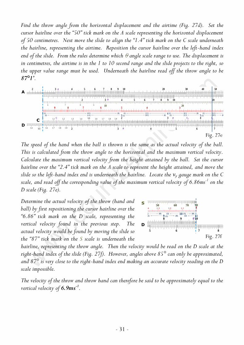
Find the throw angle from the horizontal displacement and the airtime (Fig. 27d). Set the cursor hairline over the “50” tick mark on the A scale representing the horizontal displacement of 50 centimetres. Next move the slide to align the “1.4” tick mark on the C scale underneath the hairline, representing the airtime. Reposition the cursor hairline over the left-hand index
end of the slide. From the rules determine which angle scale range to use. The displacement is in centimetres, the airtime is in the 1 to 10 second range and the slide projects to the right, so the upper value range must be used. Underneath the hairline read off the throw angle to be 87°1’.
The speed of the hand when the ball is thrown is the same as the actual velocity of the ball. This is calculated from the throw angle to the horizontal and the maximum vertical velocity. Calculate the maximum vertical velocity from the height attained by the ball. Set the cursor hairline over the “2.4” tick mark on the A scale to represent the height attained, and move the slide so the left-hand index end is underneath the hairline. Locate the vy gauge mark on the C scale, and read off the corresponding value of the maximum vertical velocity of 6.86ms-1 on the D scale (Fig. 27e).
Determine the actual velocity of the throw (hand and ball) by first repositioning the cursor hairline over the “6.86” tick mark on the D scale, representing the vertical velocity found in the previous step. The actual velocity would be found by moving the slide so the “87” tick mark on the S scale is underneath the hairline, representing the throw angle. Then the velocity would be read on the D scale at the right-hand index of the slide (Fig. 27f). However, angles above 85° can only be approximated, and 87° is very close to the right-hand index end making an accurate velocity reading on the D scale impossible.
The velocity of the throw and throw hand can therefore be said to be approximately equal to the vertical velocity of 6.9ms-1.
2 3 4 5 76 8 9 10 20 30 40 50
3 (1) 5 (1)(1.5) 7 (1)(1.5)(2) (0)
π
1 9 8 7 6 5 4 3
1 42 31.1 1.91.2 1.3 1.4 1.5 1.6 1.7 1.8
1 2 3 4 5 76 8 9 10 20
(1.5)(0.5)
3 (1) 5 (1)(1.5)(2) (0.5) (0)2 (1) 4 (1)(0.5) (1.5)(0) (2)
(2) (0.5) (0)(0) (1.5)(2)
208 976 10
π vy
n (wb)
S
Ct, bt x10-1s
B
CIbs-1
π
C C1
4 65 72 31.91.4 1.5 1.6 1.7 1.8 π
Fig. 27e
11.11.21.31.4
108 9
50 60 70 80 90 100
9 (1) 118 (1) (0) 10 (1)(2) (0)
(2) (0) (2)
90706050
g
865 7
Fig. 27f
S
D
A
D C

- 32 -
Care of the Slide Rule
The life span of your slide rule can be greatly extended by observing the following simple guidelines.
When using the slide rule, hands should be clean, dry and grease free. Care should be taken not to put undue pressure on the moving parts. Avoid knocking or dropping the slide rule. The slide rule should not be subjected to extreme changes in temperature and humidity, and prolonged exposure to direct sunlight avoided. Ideally the slide rule should be kept in a case when not in use. Do not use the slide rule for anything other than its intended purpose.
Cleaning should only be done using a soft damp cloth; the rule must not get wet and detergents should not be used. The slide can be lightly lubricated with a dry lubricant such as unscented talcum powder if necessary.

Slide rules were invented in the early 17th century, but the first slide rule for jugglers was not designed until September 2011. The first Juggler’s rule has been refined into the models listed below. All models are constructed from seasoned hardwood, either mahogany or walnut, feature precision printed paper scales faced with perspex, and a wood and perspex cursor.
S2 Simple Juggler’s rule; 3-scale SYSTEM TOMBEUR,
9 inch scale length, hairline cursor. For quick
calculations and comparisons of the basic juggling concepts of speed and height at different throw weights.
S3 Simple Juggler’s rule, 3-scale SYSTEM TOMBEUR,
5 inch scale length. Pocket version of the S2.
A2 Advanced Juggler’s rule, 9-scale SYSTEM
TOMBEUR, 9 inch scale length, hairline cursor.
Allows advanced juggling calculations and comparisons of speed and height for different throw weights incorporating variable hold times, with additional scales to calculate of angles of trajectory and object velocities in relation to pattern width. Inclusion of the conventional Mannheim scales (A, B, C & D) offers standard slide rule calculation and familiarity to all slide rule users.
All Juggler’s slide rules are handmade to order, for more information see :
www.countbelmiro.com

A2-04/2013-1