Embed Size (px)
Citation preview

Steriflow by Jordan Valve
3170 Wasson Road • Cincinnati, OH 45209
513.533.5600 • 800.543.7311 • 513.871.0105 (f)
[email protected] • www.steriflowvalve.com
JSRLFLP Series
Pressure Reducing Valves for Low Flow and Low Pressure
Biopharmaceutical and Parenteral process Gas
JSRLFLP is a high purity low flow, regulator designed and built
specifically for very low pressure hygienic, ASME BPE gas ap-
plications.
The JSRLFLP has been designed specifically for very low pres-
sure clean gas regulation in Stainless and Single Use Disposable
applications. Whether it's precise regulation for sparging, blanket-
ing, motive force, or SUD bag inflation, the JSRLFLP was built for
the job!
The durable valve body and metal trim components are machined
from ASTMA479 316L SST barstock and finished to ASME BPE
SF5, 20Ra micro-inch, (0.5 Ra micrometer) electropolished as
standard.
The valve is outfitted with a sensitive PTFE Jorlon diaphragm and
Teflon, PEEK and EPDM seats and seals that are all FDA approved,
USP Class VI compliant materials. These materials of construction
enable JSRLFLP to withstand the rigors of an autoclave if required.
Features
• Stable outlet pressure setpoints at very low pressure
• Very low set point offset (droop) especially at higher inlet
pressures
• Top entry design facilitates in-line cleaning and maintenance
• Barstock construction guarantees material integrity and
quality surface finish
• Four Cv's from 0.01 to 0.2 guarantee a valve that will fit your
specific application
• Optimized internal volume
• Proprietary Jorlon diaphragm material provides exception-
ally long life
• Soft seat material for ANSI Class VI shutoff
Documentation
The following documentation is shipped at no charge:
• Steriflow Unicert, a QC signed Certificate of Compliance for:
- Material, listing heat numbers with attached MTR’s
- Surface Finish
- FDA/USP Class VI - for all thermoplastic and elastomers
• Traceability:
- Each individual product serial number is traceable
to the Unicert serial number, heat numbers and
attached MTR’s
Other documents must be requested at time of RFQ, or order:
- ADI/TSE Free, Certified Test reports, Certificate of Origin.
applications
The JSRLFLP is a Pressure Regulating valve
ideal for low flow, low pressure precision
regulation of clean compressed air and gas
used in pharmaceutical and biopharmaceu-
tical R&D, Pilot, and Production facilities.
It is designed specifically for use on tradi-
tional Stainless Steel and Single Use Dispos-
able applications including:
• Small sterile vessels:
- Gas overlay (blanketing)
- Sparging
- SUD bag integrity testing/inflation
• Incubators
• Lyophilizers
• Time/pres filling machine product hold
vessels
Suitable for clean compressed gas, includ-
ing:
• Air
• Nitrogen
• Carbon Dioxide
• Oxygen
• Argon
• Custom gas mixtures
Sanita
ry Valv
es
JS
RLFLP S
erie
s L
ow
Flo
wLo
w P
ressure
Gas R
ed
ucin
g V
alv
es
New Options!
- Air Augment Option
- EDPM seat for low lockup and
tight shutoff

-2-
JSRLFLP SERIES LOW FLOW LOW PRESSURE REDUCING VALVE
speciFications
Sizes: 1/4" (DN8), 3/8" (DN10), 1/2" (DN15)
End Connections: ASME BPE, DIN, ISO Tri-clamp, or
Tube Weld end; NPT
Gauge Ports: 1/4" FNPT is standard. Contact Factory for
Tri-Clamp, VCR, or other alternatives.
Soft Seat Materials for ANSI Class VI Shut-off
• PTFE to +252°F (122°C) continuous or 275°F (135°C)
intermittent [not to exceed 15 min. in a one hour pe-
riod] FDA, USP Class VI
• PEEK to +350°F (177°C), FDA & USP Class VI
• EPDM to +275°F (135°C), FDA & USP Class VI
Body and Trim Material
• ASME SA479 316L (UNS 31603) is standard. EN
10272:2000 GR 1.4435, AL-6XN®, Hastelloy®C-22
and others are optional.
Diaphragm Material: Jorlon - PTFETM, FDA & USP Class VI
Maximum Inlet Pressure:
• Tube End & Tri-Clamp: 150 psig (10,3 bar)
• NPT: 150 psig (10,3 bar)
Optional Cleaning Specifications
• Clean for Oil-Free
• O2 Cleaning complying with ASTM G93-03 2011
and CGA G-4.1-2009
Pressure at Maximum Temperature:
• Tube End and Tri-Clamp: 150 psi @ 350°F (10,3 bar @
177°C) with PEEK seats; 150 psi @ 150°F (10,3 bar @
66°C) with PTFE seats; 150 psi @ 275°F (10,3 bar @
135°C) with EPDM seats
• NPT: 150 psi @ 350°F (10,3 bar @ 177°C) with PEEK
seats; 150 psi @ 150°F (10,3 bar @ 66°C) with PTFE
seats; 150 psi @ 275°F (10,3 bar @ 135°C) with EPDM
seats
Surface Finish:
• Wetted Internal surface finish: Mechanically pol-
ished, and electropolished to ASME BPE SF5, 20 Ra
μin (0.5 Ra μm) as standard
• Exterior surface finish: Mechanically polished to 40
Ra μin (1.0 Ra μm) as standard
• Other finishes available upon request
Maximum Pressure Drop:
• Tube End and Tri-Clamp: 150 psi (10,3 bar)
• NPT: 150 psi (10,3 bar)
Spring Ranges: 1 – 75 psi (0,07 – 5,2 bar), 25 - 100 psi
(1,7 - 6,9 bar)
Flow Capacities: Cv 0.012, Cv 0.03, Cv 0.08, Cv 0.20
(Kv 0,010, Kv 0,026, Kv 0,069, Kv 0,173)
Options
• Oxygen cleaning and certification
• Panel Mounting
• Captured Vent
• Self Relieving
• Gauge Ports, Pressure Gauges
• Air Augment
Note: For a complete ancillary list of all wetted and un-wetted
material specifications, please contact Steriflow Valve.

option illustrations
Panel Mount Option Captured Vent Option (1/8" NPT)
JSRLFLP SERIES LOW FLOW LOW PRESSURE REDUCING VALVE
-3-
Self-Relieving Option
option DeFinition
Captured Venting
The captured vent option provides a means to vent downsteam, self-relieved gas. To enable this function, a 1/8" FNPT
collar is installed on the spring housing. This feature provides a means to safely transport toxic or hazardous, self-
relieved downstream gas away from the spring housing via tubing to a safe area.
!VIP! This option must be specified with the Self-Relieving* option if the user wishes to transport self-relieved
vented gas to a safe location.
Air Augment
The air augment option provides a means for air loading the valve spring housing for automated control. To enable
this function a 1/8" FNPT collar is installed on the spring housing (the same one used for the captured vent option),
and a Teflon seal nut is included to seal the adjusting screw threads to prevent leakage. The 1/8" FNPT port is used
as the input fitting for loading the spring housing with instrument air to completely automate or augment manual
regulator control. An I/P transducer, or a small, self-relieving air set PRV regulator is required (ordered separately) to
regulate the instrument air pressure.
*Self-Relieving The self-relieving option provides an internal mechanism to vent downstream pressure increase (above the set-point)
though the spring housing and out a vent hole in the spring housing. If the gas is toxic, or dangerous - the Captured-
Vent option (above) must also be specified. The Self-Relieving option allows for immediate pressure reduction when
reducing the set point, provides a means to automatically relieve downstream pressure build-up when flow stops and
the valve starts to close (sometimes called Lock-up), and alleviates pressure equalization across the orifice when the
regulator is not operating.
!VIP! If selecting the Self-relieving option for a Toxic or Hazardous gas - the Captured Vent option must be
selected. You cannot Air-Load if the Self-Relieving option is specified.
Panel Mount The panel mounted regulator option illustrated on the next page requires a panel cut out of 1-1/2". When this option is
specified, the regulator comes fitted with a threaded spring housing, and a panel mounting ring to secure the regula-
tor to the panel.
Gauge Ports - Pressure Gauge For inlet and outlet pressure gauges (and the gauges) are available as standard options
JSRLFLP SERIES LOW FLOW LOW PRESSURE REDUCING VALVE
-4-
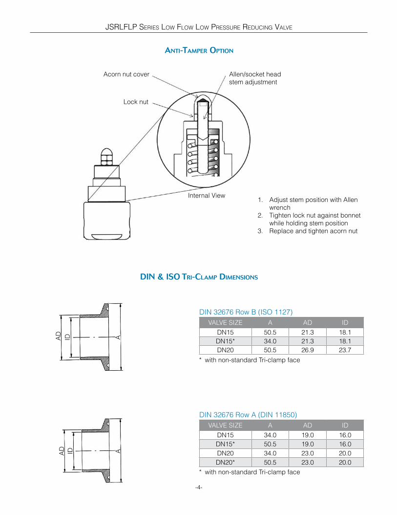
anti-tamper option
AD
ID A
AD ID A
DIN 32676 Row B (ISO 1127)
VALVE SIZE A AD ID
DN15 50.5 21.3 18.1
DN15* 34.0 21.3 18.1
DN20 50.5 26.9 23.7
DIN 32676 Row A (DIN 11850)
VALVE SIZE A AD ID
DN15 34.0 19.0 16.0
DN15* 50.5 19.0 16.0
DN20 34.0 23.0 20.0
DN20* 50.5 23.0 20.0
Din & iso tri-clamp Dimensions
Acorn nut cover
Lock nut
Allen/socket head
stem adjustment
Internal View1. Adjust stem position with Allen
wrench
2. Tighten lock nut against bonnet
while holding stem position
3. Replace and tighten acorn nut
* with non-standard Tri-clamp face
* with non-standard Tri-clamp face
JSRLFLP SERIES LOW FLOW LOW PRESSURE REDUCING VALVE
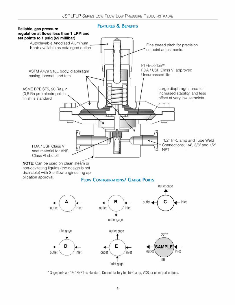
Features & BeneFits
-5-
Fine thread pitch for precision
setpoint adjustments.
ASTM A479 316L body, diaphragm
casing, bonnet, and trim
ASME BPE SF5, 20 Ra µin
(0,5 Ra µm) electropolish
finish is standard
FDA / USP Class VI
seat material for ANSI
Class VI shutoff
1/2" Tri-Clamp and Tube Weld
Connections; 1/4", 3/8" and 1/2"
NPT
PTFE-JorlonTM
FDA / USP Class VI approved
Unsurpassed life
Flow conFigurations/ gauge ports
outlet inlet
outlet gage
inlet gage
* Gage ports are 1/4" FNPT as standard. Consult factory for Tri-Clamp, VCR, or other port options.
A B
D E
outlet inlet
outlet inlet outlet inlet
inlet gage outlet gage
outlet gage
outlet inlet
SAMPLE
C
outlet inlet
270°
90°
Autoclavable Anodized Aluminum
Knob available as cataloged option
Reliable, gas pressure
regulation at flows less than 1 LPM and
set points to 1 psig (69 millibar)
Large diaphragm area for
increased stability, and less
offset at very low setpoints
NOTE: Can be used on clean steam or
non-cavitating liquids (the design is not
drainable) with Steriflow engineering ap-
plication approval.

JSRLFLP SERIES LOW FLOW LOW PRESSURE REDUCING VALVE
-6-
• JSRLFLP Series with ASME BPE Tri-Clamp
Ends, Inches (Metric)
VALVE SIZE A
1/2" (DN15) 4.07 (103,4)
3/4" (DN20) 4.07 (103,4)
Dimensions
5.10* (129,5)5.93
(150,6)
A
• JSRLFLP Series with FNPT/SW Ends, Inches
(Metric)
VALVE SIZE A
1/4" (DN8) 2.00 (50,8)
3/8" (DN10) 2.00 (50,8)
1/2" (DN15) 2.75 (69,9)
• JSRLFLP Series with ASME BPE Tube Ends,
Inches (Metric)
VALVE SIZE A
1/2" (DN15) 8.85 (224,8)
3/4" (DN20) 8.85 (224,8)
Ø5.7 (144,8)
Ø5.70
(144,8)
5.93(150.6)
5.10(129.5)
A
*Add 0.75" (19,1) for easy removal

JSRLFLP SERIES LOW FLOW LOW PRESSURE REDUCING VALVE
-7-
Dimensions, in (mm)- Dn15,20 For Din 32676 row B (iso 1127)
cV trim selection instructions
anD Din 32676 row a (iso 11850)
Ø5.70
(144,8)
5.83
(148.2)5.00
(126.9)
7.48
(190)
JSRLFLP:Body Dimensions for:
DN15, DN20
DIN 32676 Row B (ISO 1127)
DIN 32676 Row A (DIN 11850)
To select a valve with the proper Cv:
1. Select a graph on the following twelve pages that best represents your outlet pressure set point and flow range
2. Looking at that graph, select the closest inlet pressure line (horizontal sloped line, P1) that best reflects your ap-
plication's actual inlet pressure. That line indicates the Pressure/Flow capabilities and offset (droop) of the trim
(Flow Coefficient, Cv) under flowing conditions.
Note: If your exact outlet pressure set point or inlet pressure is not listed you will have to interpolate.
- Your particular inlet pressure line will be very similar in length and slope to the line chosen on any
particular graph.
- The same is true for your outlet pressure set point, simply shift the line up or down.
3. The Cv is listed in bold at the upper left of the page of your chosen graph. You will need that for model number
selection (See page 20).

Flow Data For cV trim selection
The graphs illustrate the change or "droop" in outlet pressures as the flow rate increases, and the lockup (setpoint rise) as flow decreases and approaches zero.
Flow Coefficient: 0.012
Maximum inlet pressure: 150 psig (10,3 bar)
-8-
Pressure Control Range
Range Spring: 0-75 psig (0-5,2 bar)
Set Point: 15 psig
Pressure Control Range
Range Spring: 0-75 psig (0-5,2 bar)
Set Point: 5 psig
Pressure Control Range
Range Spring: 0-75 psig (0-5,2 bar)
Set Point: 1 psig
Pressure Control Range
Range Spring: 0-75 psig (0-5,2 bar)
Set Point: 2 psig
Pressure Control Range
Range Spring: 0-75 psig (0-5,2 bar)
Set Point: 10 psig
0.2
0
0.4
0.6
0.8
1
1.2
0
0 0.40
0.09
0.121.8
1.61.41.2
1
0
0 1.5
0.3
0.70.8
8
6
4
0
0.5
10
12
0
0.05
0.1
1
0.5
0
0.152
2.5
0.2
Out
let P
ress
ure
(psi
)O
utle
t Pre
ssur
e (p
si)
Out
let P
ress
ure
(psi
)
Out
let P
ress
ure
(psi
)O
utle
t Pre
ssur
e (p
si)
Out
let P
ress
ure
(bar
)O
utle
t Pre
ssur
e (b
ar)
Out
let P
ress
ure
(bar
)O
utle
t Pre
ssur
e (b
ar)
Out
let P
ress
ure
(bar
)
Air Flow (L/min)
Air Flow (L/min)
Air Flow (L/min)Air Flow (L/min)
Air Flow (SCFM)
Air Flow (SCFM) Air Flow (SCFM)
Air Flow (SCFM)Air Flow (SCFM)0.1
Pressure Control Range
Range Spring: 0-75 psig (0-5,2 bar)
Set Point: 20 psig
0
0.2
1
1.2
5
0
0.8
1.4
10
15
1.6
Out
let P
ress
ure
(psi
)
Out
let P
ress
ure
(bar
)
Air Flow (L/min)
Air Flow (SCFM)
0.6
8642 10 12 14
5 15 20 35 40302510
4
3
2
1
5
6
0
0.2
0.1
0.25
0 0.50
86
42
1012
1416
P1=50 psiP1=75 psiP1=100 psi
P1=50 psiP1=75 psi
P1=100 psi
P1=75 psi
P1=100 psi
1.5
0.5
5 10 15 20 25 30 35 40
0.4
P1=75 psi P1=100 psi
P1=50 psiP1=75 psi P1=100 psi
P1=35 psi
P1=50 psi
P1=75 psiP1=100 psi0.03
P1=10 psi
1
0.15
0.05
5 15 30 35 40252010
5 45 15 35 40302010Air Flow (L/min)
1
0.4
0.6
0 0.5 1 1.5
0.8
0.2 0.3 0.5
1.5
18
20
0 10.5 1.5
2015105 25 30 35 403
2
0.60.40.2
JSRLFLP SERIES LOW FLOW LOW PRESSURE REDUCING VALVE
0.07
0.05
0.01P1=25 psi
P1=35 psi
0 1.50.5 1
0.3
0.350.4
P1=35 psi
P1=10 psi
P1=25 psi
P1=50 psiP1=35 psi
P1=25 psi
0.20.1
0
P1=35 psiP1=25 psi
P1=25 psi
P1=10 psi
P1=50 psi
P1=35 psi
P1=25 psi

Flow Data For cV trim selection
-9-
The graphs illustrate the change or "droop" in outlet pressures as the flow rate increases, and the lockup (setpoint rise) as flow decreases and approaches zero.
Flow Coefficient: 0.012
Maximum inlet pressure: 150 psig (10,3 bar)
Pressure Control Range
Range Spring: 0-75 psig (0-5,2 bar)
Set Point: 45 psig
Pressure Control Range
Range Spring: 0-75 psig (0-5,2 bar)
Set Point: 35 psig
Pressure Control Range
Range Spring: 0-75 psig (0-5,2 bar)
Set Point: 25 psig
Pressure Control Range
Range Spring: 0-75 psig (0-5,2 bar)
Set Point: 30 psig
Pressure Control Range
Range Spring: 0-75 psig (0-5,2 bar)
Set Point: 40 psig
0.5
0
1
1.5
2
2.5
3
0 10
1
230
25
20
15
10
5
0
1.5
0
0
Out
let P
ress
ure
(psi
)O
utle
t Pre
ssur
e (p
si)
Out
let P
ress
ure
(psi
)
Out
let P
ress
ure
(psi
)O
utle
t Pre
ssur
e (p
si)
Out
let P
ress
ure
(bar
)
Out
let P
ress
ure
(bar
)O
utle
t Pre
ssur
e (b
ar)
Out
let P
ress
ure
(bar
)
Air Flow (L/min)
Air Flow (L/min)
Air Flow (L/min)Air Flow (L/min)
Air Flow (SCFM)
Air Flow (SCFM) Air Flow (SCFM)
Air Flow (SCFM)Air Flow (SCFM)
1.5
15105 20 30 35 40
0 0.50
2
1
2.5
00
3025201510
35404550
P1=75 psiP1=100 psi
P1=75 psi
P1=100 psi
P1=100 psi
P1=75 psi P1=100 psi
P1=35 psiP1=50 psi P1=75 psi
P1=100 psi
0.5
1
1
1.5
0.5
Air Flow (L/min)
0.5
3530
25201510
0
5
40
1.5
1.5
00
JSRLFLP SERIES LOW FLOW LOW PRESSURE REDUCING VALVE
25
P1=50 psiP1=35 psi
P1=50 psi
15105 20 30 35 4025
15105 20 30 35 4025
P1=75 psi
0.5
15105 20 30 35 4025
15105 20 30 35 4025
15105 20 30 35 4025
0.5
0
11.522.53
0.5
0
1
1.5
2
2.5
3
0.5 1 1.5
0 0.5 1 1.5
353025201510
05
4045
P1=50 psi
Out
let P
ress
ure
(bar
)
1
2
1.5
0.5
3.5
4
Out
let P
ress
ure
(bar
)
Air Flow (SCFM)
Air Flow (L/min)
Pressure Control Range
Range Spring: 0-75 psig (0-5,2 bar)
Set Point: 50 psig
P1=100 psiP1=75 psi
0
20
10
30
40
50
60
Out
let P
ress
ure
(psi
)1 1.50.5
3530
25
20
15
10
5

Flow Data For cV trim selection
The graphs illustrate the change or "droop" in outlet pressures as the flow rate increases, and the lockup (setpoint rise) as flow decreases and approaches zero.
Flow Coefficient: 0.012
Maximum inlet pressure: 150 psig (10,3 bar)
-10-
Pressure Control Range
Range Spring: 0-75 psig (0-5,2 bar)
Set Point: 75 psig
Pressure Control Range
Range Spring: 0-75 psig (0-5,2 bar)
Set Point: 65 psig
Pressure Control Range
Range Spring: 0-75 psig (0-5,2 bar)
Set Point: 55 psig
Pressure Control Range
Range Spring: 0-75 psig (0-5,2 bar)
Set Point: 60 psig
Pressure Control Range
Range Spring: 0-75 psig (0-5,2 bar)
Set Point: 70 psig
0 1.5
Out
let P
ress
ure
(psi
)O
utle
t Pre
ssur
e (p
si)
Out
let P
ress
ure
(psi
)
Out
let P
ress
ure
(psi
)O
utle
t Pre
ssur
e (p
si)
Out
let P
ress
ure
(bar
)O
utle
t Pre
ssur
e (b
ar)
Out
let P
ress
ure
(bar
)O
utle
t Pre
ssur
e (b
ar)
Out
let P
ress
ure
(bar
)
Air Flow (L/min)
Air Flow (L/min)
Air Flow (L/min)Air Flow (L/min)
Air Flow (SCFM)
Air Flow (SCFM) Air Flow (SCFM)
Air Flow (SCFM)Air Flow (SCFM)
0
0 0.5
P1=75 psi
P1=100 psi
P1=75 psi
P1=100 psi
P1=100 psi
0.5
P1=75 psi P1=100 psi
P1=75 psiP1=100 psi
1
Air Flow (L/min)
1
1.5
0 10.5 1.5
JSRLFLP SERIES LOW FLOW LOW PRESSURE REDUCING VALVE
0 1.50.5 1
15105 20 30 35 4025
15105 20 30 35 4025
15105 20 30 35 4025
15105 20 30 35 4025
15105 20 30 35 4025
0 1.50.5 1
0.511.522.533.54
0.50
1
1.522.533.5
4
0
1
2
3
4
5
0
1
2
3
4
5
0.50
11.522.533.545
4.5
0
20
10
30
40
50
60
0
20
10
30
40
50
60
70
0
20
10
30
40
50
60
70
0
2010
30
4050
60
7080
80
0
2010
3040
5060
70

Flow Data For cV trim selection
-11-
The graphs illustrate the change or "droop" in outlet pressures as the flow rate increases, and the lockup (setpoint rise) as flow decreases and approaches zero.Flow Coefficient: 0.03
Maximum inlet pressure: 150 psig (10,3 bar)
Pressure Control Range
Range Spring: 0-75 psig (0-5,2 bar)
Set Point: 15 psig
Pressure Control Range
Range Spring: 0-75 psig (0-5,2 bar)
Set Point: 5 psig
Pressure Control Range
Range Spring: 0-75 psig (0-5,2 bar)
Set Point: 1 psig
Pressure Control Range
Range Spring: 0-75 psig (0-5,2 bar)
Set Point: 2 psig
Pressure Control Range
Range Spring: 0-75 psig (0-5,2 bar)
Set Point: 10 psig
0 20
0.4
0.6
1
0.8
1.21618
1412
1086
420
0
0.05
0
0.10.15
0.35
0.46
5
3
2
0
00
0.04
0.06
2015105
1.61.4
0.8
0.60.4
01.5
1.8
0.02
0
0.1
0.30.4
0.812
0
0.2
8
2
0
0.05
2
1.5
1
0.5
2.5
3 0.2
Out
let P
ress
ure
(psi
)O
utle
t Pre
ssur
e (p
si)
Out
let P
ress
ure
(psi
)
Out
let P
ress
ure
(psi
)O
utle
t Pre
ssur
e (p
si)
Out
let P
ress
ure
(bar
)O
utle
t Pre
ssur
e (b
ar)
Out
let P
ress
ure
(bar
)O
utle
t Pre
ssur
e (b
ar)
Out
let P
ress
ure
(bar
)
Air Flow (L/min)
Air Flow (L/min) Air Flow (L/min)
Air Flow (L/min)Air Flow (L/min)
Air Flow (SCFM)
Air Flow (SCFM) Air Flow (SCFM)
Air Flow (SCFM)Air Flow (SCFM)
P1=10 psi
P1=25 psi P1=75 psi P1=100 psi
25
1
4
0
10
4
6
30 35
10.5
0.5 1 1.5
P1=75 psiP1=100 psi
0.5
P1=100 psi
P1=75 psi
P1=100 psi
P1=75 psi
P1=100 psi
0.08
0.12
0.10.15
0.1
Pressure Control Range
Range Spring: 0-75 psig (0-5,2 bar)
Set Point: 20 psig
40
1.21
0.2
2015105 25 30 35 40 45
0.3
0.25
0.2
P1=35 psi P1=50 psi
P1=35 psi
P1=25 psiP1=10 psi
P1=50 psi
2015105 25 30 35 40 45 50 55
1 1.5
0.2
P1=35 psi
P1=25 psi P1=50 psiP1=75 psi
0 1.510.5
201510 25 30 35 405
P1=10 psi
P1=25 psi
P1=35 psi
P1=50 psi
2015105 25 30 35 40 45 50 55
0 0.5 1 1.5
0.7
0.6
0.5P1=25 psi
P1=35 psi
P1=50 psi
P1=75 psi P1=100 psi
P1=25 psi
P1=35 psi
P1=50 psi
20
15
10
5
00
Air Flow (SCFM)0.5 1 1.5 2
0
0.4
0.6
1
0.8
1.2
Out
let P
ress
ure
(bar
)
0.2
1.41.6
20155 55Air Flow (L/min)
10 25 30 5035 40 45
Out
let P
ress
ure
(psi
)
JSRLFLP SERIES LOW FLOW LOW PRESSURE REDUCING VALVE
Flow Data For cV trim selection
-12-
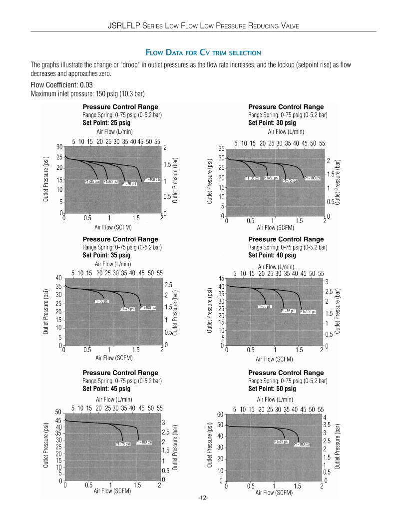
The graphs illustrate the change or "droop" in outlet pressures as the flow rate increases, and the lockup (setpoint rise) as flow decreases and approaches zero.
Flow Coefficient: 0.03
Maximum inlet pressure: 150 psig (10,3 bar)
Pressure Control Range
Range Spring: 0-75 psig (0-5,2 bar)
Set Point: 45 psig
Pressure Control Range
Range Spring: 0-75 psig (0-5,2 bar)
Set Point: 35 psig
Pressure Control Range
Range Spring: 0-75 psig (0-5,2 bar)
Set Point: 25 psig
Pressure Control Range
Range Spring: 0-75 psig (0-5,2 bar)
Set Point: 30 psig
Pressure Control Range
Range Spring: 0-75 psig (0-5,2 bar)
Set Point: 40 psig
0.5
0
1
1.5
2
2.5
3
0
0 1 20
1
230
25
20
15
10
5
0
1.5
0.5
00
0.5
1.5
235302520
0
1
2.540
453
00
0.5
1
20
15
10
0
1.5
30
35
2
Out
let P
ress
ure
(psi
)O
utle
t Pre
ssur
e (p
si)
Out
let P
ress
ure
(psi
)
Out
let P
ress
ure
(psi
)O
utle
t Pre
ssur
e (p
si)
Out
let P
ress
ure
(bar
)O
utle
t Pre
ssur
e (b
ar)
Out
let P
ress
ure
(bar
)O
utle
t Pre
ssur
e (b
ar)
Out
let P
ress
ure
(bar
)
Air Flow (L/min)
Air Flow (L/min) Air Flow (L/min)
Air Flow (L/min)Air Flow (L/min)
Air Flow (SCFM)
Air Flow (SCFM) Air Flow (SCFM)
Air Flow (SCFM)Air Flow (SCFM)
0.5 1.5
Pressure Control Range
Range Spring: 0-75 psig (0-5,2 bar)
Set Point: 50 psig
0
0.5
2.5
340
30
20
0
2
3.550
60 4
Out
let P
ress
ure
(psi
)
Out
let P
ress
ure
(bar
)
Air Flow (L/min)
Air Flow (SCFM)0
1.5
2015105 25 30 35 40 45 50 55
15105 25 30 45 50 55403520
30
25
2015
10
5
35
40
0 10.5 1.50
1
2
1.5
0.5
2
2.5
0 10.5 1.5 20
3025201510
5
354045
5015105 45 50 55403520 25 30
P1=35 psi P1=50 psiP1=75 psi
P1=100 psi
P1=50 psi
P1=75 psi P1=100 psi
P1=75 psi P1=100 psi
2015105 25 30 35 40 45 50 55
25
5
1 20.5 1.5
1 20.5 1.5
1 20.5 1.5
2015105 25 30 35 40 45 50 55
2015105 25 30 35 40 45 50 55
15
105
110
P1=75 psiP1=100 psi
P1=50 psiP1=75 psi P1=100 psi
P1=35 psi P1=50 psiP1=75 psi
P1=100 psi
JSRLFLP SERIES LOW FLOW LOW PRESSURE REDUCING VALVE

Flow Data For cV trim selection
The graphs illustrate the change or "droop" in outlet pressures as the flow rate increases, and the lockup (setpoint rise) as flow decreases and approaches zero.
Flow Coefficient: 0.03
Maximum inlet pressure: 150 psig (10,3 bar)
Pressure Control Range
Range Spring: 0-75 psig (0-5,2 bar)
Set Point: 75 psig
Pressure Control Range
Range Spring: 0-75 psig (0-5,2 bar)
Set Point: 65 psig
Pressure Control Range
Range Spring: 0-75 psig (0-5,2 bar)
Set Point: 55 psig
Pressure Control Range
Range Spring: 0-75 psig (0-5,2 bar)
Set Point: 60 psig
Pressure Control Range
Range Spring: 0-75 psig (0-5,2 bar)
Set Point: 70 psig
1
0
2
3
4
5
6
0
0 1 2 0
1
460
50
40
30
10
0
1.5
0.5
00
2
3
70
6050
40
0
1
4
805
000.51
40
30
20
0
460
70 4.5
Out
let P
ress
ure
(psi
)O
utle
t Pre
ssur
e (p
si)
Out
let P
ress
ure
(psi
)
Out
let P
ress
ure
(psi
)O
utle
t Pre
ssur
e (p
si)
Out
let P
ress
ure
(bar
)O
utle
t Pre
ssur
e (b
ar)
Out
let P
ress
ure
(bar
)O
utle
t Pre
ssur
e (b
ar)
Out
let P
ress
ure
(bar
)
Air Flow (L/min)
Air Flow (L/min) Air Flow (L/min)
Air Flow (L/min)Air Flow (L/min)
Air Flow (SCFM)
Air Flow (SCFM) Air Flow (SCFM)
Air Flow (SCFM)Air Flow (SCFM)
0.5 1.5
2015105 25 30 35 40 45 50 55
15105 25 30 45 50 55403520
4030
20
10
50
60
0 10.5 1.50
3
4
2
2
5
0 10.5 1.5 20
302010
50
708090
15105 45 50 55403520 25 30
P1=75 psi
P1=100 psi
P1=75 psi P1=100 psi
P1=100 psi
2015105 25 30 35 40 45 50 55
50
10
1 20.5 1.5
1 20.5 1.5
2015105 25 30 35 40 45 50 55
3020
10
P1=75 psiP1=100 psi
P1=75 psiP1=100 psi
20
3.5
3
2.52
70
80
1
40
60
1.5
22.533.5
-13-
JSRLFLP SERIES LOW FLOW LOW PRESSURE REDUCING VALVE

JSRLFLP SERIES LOW FLOW LOW PRESSURE REDUCING VALVE
Flow Data For cV trim selection
-14-
The graphs illustrate the change or "droop" in outlet pressures as the flow rate increases, and the lockup (setpoint rise) as flow decreases and approaches zero.
Flow Coefficient: 0.08
Maximum inlet pressure: 150 psig (10,3 bar)
Pressure Control Range
Range Spring: 0-75 psig (0-5,2 bar)
Set Point: 15 psig
Pressure Control Range
Range Spring: 0-75 psig (0-5,2 bar)
Set Point: 5 psig
Pressure Control Range
Range Spring: 0-75 psig (0-5,2 bar)
Set Point: 1 psig
Pressure Control Range
Range Spring: 0-75 psig (0-5,2 bar)
Set Point: 2 psig
Pressure Control Range
Range Spring: 0-75 psig (0-5,2 bar)
Set Point: 10 psig
0.2
0
0.4
0.6
0.8
1
1.2
0
0 10
0.08
0.121.81.6
1.41.2
1
0.8
0
0.1
0.04
000.1
0.5
0.68
6
4
2
0
0.3
0.710
12 0.8
00
0.05
0.11.5
1
0
0.152.5
3 0.2
Out
let P
ress
ure
(psi
)O
utle
t Pre
ssur
e (p
si)
Out
let P
ress
ure
(psi
)
Out
let P
ress
ure
(psi
)O
utle
t Pre
ssur
e (p
si)
Out
let P
ress
ure
(bar
)O
utle
t Pre
ssur
e (b
ar)
Out
let P
ress
ure
(bar
)O
utle
t Pre
ssur
e (b
ar)
Out
let P
ress
ure
(bar
)
Air Flow (L/min)
Air Flow (L/min)
Air Flow (L/min)Air Flow (L/min)
Air Flow (SCFM)
Air Flow (SCFM) Air Flow (SCFM)
Air Flow (SCFM)Air Flow (SCFM)
0.5 1.5
Pressure Control Range
Range Spring: 0-75 psig (0-5,2 bar)
Set Point: 20 psig
00.2
11.2
15
10
5
0
0.8
1.420
251.6
Out
let P
ress
ure
(psi
)
Out
let P
ress
ure
(bar
)
Air Flow (L/min)
Air Flow (SCFM)
0.6
2015105 25 30 35 40
15 45 60 105120 135907530
5
4
3
2
1
6
7
0 31 50
0.15
0.4
0.3
0.1
0.45
0 21 3 40
10
86
4
2
12141618
P1=10 psi P1=50 psi
P1=75 psi
P1=100 psi
P1=50 psiP1=75 psi P1=100 psi
P1=75 psi P1=100 psi
2
0.5
1 32
2 41 3
20 40 60 80 100 120 140 160
0.4
P1=75 psi P1=100 psi
P1=50 psi P1=75 psi
P1=100 psi
P1=35 psiP1=50 psi
P1=75 psiP1=100 psi
0.60.40.2
0.06
0.02
P1=35 psi
P1=25 psi
5
2 4
P1=35 psi
P1=25 psiP1=10 psi
0.35
0.250.2
0.05
15 45 60 105120 135907530
15 45 60 105120 135907530
P1=50 psi
P1=35 psi
P1=25 psi
2010 30 40 6050
P1=25 psi
P1=10 psi
Air Flow (L/min)
5
0.2
0.4
P1=35 psi
P1=25 psi
0 21 3 4 5 6
P1=50 psi
P1=35 psi
P1=25 psi
JSRLFLP SERIES LOW FLOW LOW PRESSURE REDUCING VALVE
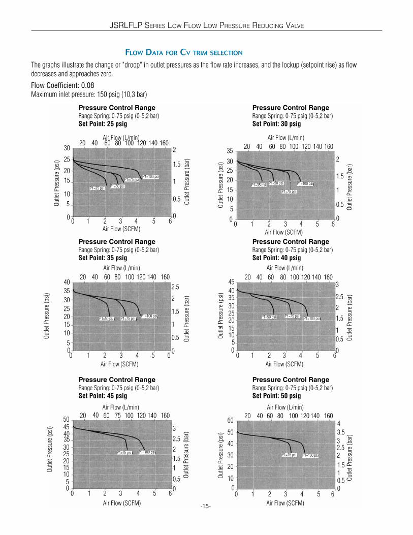
Flow Data For cV trim selection
The graphs illustrate the change or "droop" in outlet pressures as the flow rate increases, and the lockup (setpoint rise) as flow decreases and approaches zero.
Flow Coefficient: 0.08
Maximum inlet pressure: 150 psig (10,3 bar)
-15-
Pressure Control Range
Range Spring: 0-75 psig (0-5,2 bar)
Set Point: 45 psig
Pressure Control Range
Range Spring: 0-75 psig (0-5,2 bar)
Set Point: 35 psig
Pressure Control Range
Range Spring: 0-75 psig (0-5,2 bar)
Set Point: 25 psig
Pressure Control Range
Range Spring: 0-75 psig (0-5,2 bar)
Set Point: 30 psig
Pressure Control Range
Range Spring: 0-75 psig (0-5,2 bar)
Set Point: 40 psig
0.5
0
1
1.5
2
2.5
3
0
0 40
1
230
25
20
15
10
0
1.5
00
0.5
2.5
3
35
302520
0
1.5
40
45
0
0.5
115
10
0
1.525
30 2
Out
let P
ress
ure
(psi
)
Out
let P
ress
ure
(psi
)O
utle
t Pre
ssur
e (p
si)
Out
let P
ress
ure
(psi
)O
utle
t Pre
ssur
e (p
si)
Out
let P
ress
ure
(bar
)O
utle
t Pre
ssur
e (b
ar)
Out
let P
ress
ure
(bar
)O
utle
t Pre
ssur
e (b
ar)
Out
let P
ress
ure
(bar
)
Air Flow (L/min)
Air Flow (L/min)
Air Flow (L/min)Air Flow (L/min)
Air Flow (SCFM)
Air Flow (SCFM) Air Flow (SCFM)
Air Flow (SCFM)Air Flow (SCFM)
1 5
Pressure Control Range
Range Spring: 0-75 psig (0-5,2 bar)
Set Point: 50 psig
00.5
2.53
30
20
10
0
2
3.5
40
50
4
Out
let P
ress
ure
(psi
)
Out
let P
ress
ure
(bar
)
Air Flow (L/min)
Air Flow (SCFM)
1.5
80604020 100 120 140 160
20 60 80 140 16012010040
30
252015
10
35
40
0 31 50
2
1
2.5
0 21 3 40
252015105
30354045
P1=50 psi
P1=75 psiP1=100 psi
P1=50 psi P1=75 psiP1=100 psi
P1=75 psi P1=100 psi
20
5
2 41 3
20 40 60 80 100 120 140 160
1
P1=75 psi P1=100 psi
P1=50 psi P1=75 psiP1=100 psi
P1=35 psi P1=50 psi
P1=75 psi
P1=100 psi
0.5
P1=35 psi
5
2 4
1.5
0.5
20 60 120 140 1601007540
20 60 120 140 1601008040
Air Flow (L/min)
5
1
2
0 21 3 4 5 6
5
2 3 6
5
6
6
50 60
6
0 2 41 3 5 6
80604020 100 120 140 16035
1510
5
Flow Data For cV trim selection
-16-
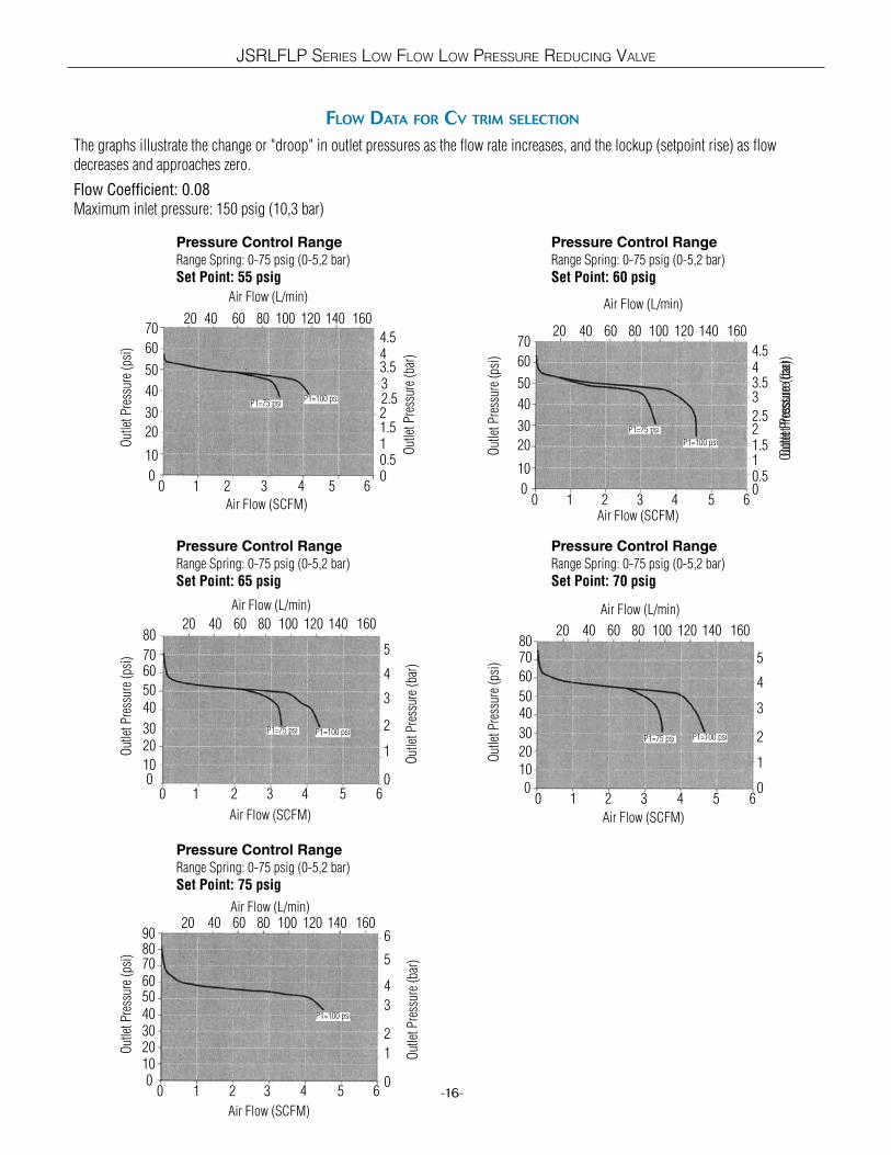
The graphs illustrate the change or "droop" in outlet pressures as the flow rate increases, and the lockup (setpoint rise) as flow decreases and approaches zero.
Flow Coefficient: 0.08
Maximum inlet pressure: 150 psig (10,3 bar)
Pressure Control Range
Range Spring: 0-75 psig (0-5,2 bar)
Set Point: 75 psig
Pressure Control Range
Range Spring: 0-75 psig (0-5,2 bar)
Set Point: 65 psig
Pressure Control Range
Range Spring: 0-75 psig (0-5,2 bar)
Set Point: 55 psig
Pressure Control Range
Range Spring: 0-75 psig (0-5,2 bar)
Set Point: 60 psig
Pressure Control Range
Range Spring: 0-75 psig (0-5,2 bar)
Set Point: 70 psig
1
0
2
3
4
5
6
0 50
3.5
4.570
60
50
40
30
20
0
4
2.5
0
40
30
20
10
0
50
60
0
Out
let P
ress
ure
(psi
)O
utle
t Pre
ssur
e (p
si)
Out
let P
ress
ure
(psi
)
Out
let P
ress
ure
(psi
)O
utle
t Pre
ssur
e (p
si)
Out
let P
ress
ure
(bar
)O
utle
t Pre
ssur
e (b
ar)
Out
let P
ress
ure
(bar
)O
utle
t Pre
ssur
e (b
ar)
Out
let P
ress
ure
(bar
)
Air Flow (L/min)
Air Flow (L/min)
Air Flow (L/min)Air Flow (L/min)
Air Flow (SCFM)
Air Flow (SCFM) Air Flow (SCFM)
Air Flow (SCFM)Air Flow (SCFM)
2 6
80604020 100 120 140 160
0 31 50
4
2
5
0 21 3 40
5040302010
60708090
P1=75 psiP1=100 psi
P1=75 psi P1=100 psi
P1=100 psi
1 32
2 41 3
P1=75 psi P1=100 psi
P1=75 psi
P1=100 psi
10
3
2
5
2 4
3
1
Air Flow (L/min)
5
1.510.5
431
80604020 100 120 140 160
7060
5040
3020
010
80
6
80604020 100 120 140 160
80604020 100 120 140 160
80604020 100 120 140 160
6
6
7080
0
4
2
5
3
1
0
4.54
3
21.510.5
2.5
3.5
5 64
70
60
50
40
30
20
0
10
JSRLFLP SERIES LOW FLOW LOW PRESSURE REDUCING VALVE
JSRLFLP SERIES LOW FLOW LOW PRESSURE REDUCING VALVE
Flow Data For cV trim selection
-17-
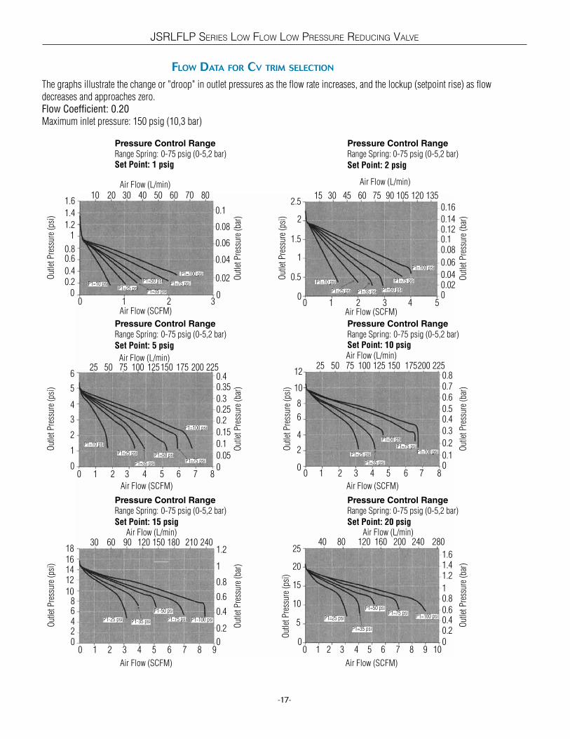
The graphs illustrate the change or "droop" in outlet pressures as the flow rate increases, and the lockup (setpoint rise) as flow decreases and approaches zero.Flow Coefficient: 0.20
Maximum inlet pressure: 150 psig (10,3 bar)
Pressure Control Range
Range Spring: 0-75 psig (0-5,2 bar)
Set Point: 15 psig
Pressure Control Range
Range Spring: 0-75 psig (0-5,2 bar)
Set Point: 5 psig
Pressure Control Range
Range Spring: 0-75 psig (0-5,2 bar)Set Point: 1 psig
Pressure Control Range
Range Spring: 0-75 psig (0-5,2 bar)
Set Point: 2 psig
Pressure Control Range
Range Spring: 0-75 psig (0-5,2 bar)Set Point: 10 psig
0 3 7 8 9
0.2
0
0.4
0.6
0.8
1
1.21801209030
18161412
1086420
0 2 5 8
0.05
0
0.1
0.15
0.2
0.3
0.35
200125100256
5
4
3
2
1
0
0.25
0.4
0 1 2 30
0.04
0.06
0.08
0.1
80502010
1.21
0.80.6
0.40.2
0
1.4
0.02
0 1 3 600.1
0.2
0.3
0.5
0.6
100755025
8
6
4
2
0
0.4
0.7
4 5 7
10
12125 150 175 225
0.8
0 200.020.04
0.06
0.10.12
6015
1.5
1
0.5
0
0.08
0.14
4
2
2.5105 135
0.16
Out
let P
ress
ure
(psi
)O
utle
t Pre
ssur
e (p
si)
Out
let P
ress
ure
(psi
)
Out
let P
ress
ure
(psi
)O
utle
t Pre
ssur
e (p
si)
Out
let P
ress
ure
(bar
)O
utle
t Pre
ssur
e (b
ar)
Out
let P
ress
ure
(bar
)O
utle
t Pre
ssur
e (b
ar)
Out
let P
ress
ure
(bar
)
Air Flow (L/min)
Air Flow (L/min) Air Flow (L/min)
Air Flow (L/min)Air Flow (L/min)
Air Flow (SCFM)
Air Flow (SCFM) Air Flow (SCFM)
Air Flow (SCFM)Air Flow (SCFM)
P1=10 psiP1=25 psi
P1=35 psi
P1=50 psiP1=75 psi
P1=100 psi
1 3 5
Pressure Control Range
Range Spring: 0-75 psig (0-5,2 bar)
Set Point: 20 psig
100.20.4
1
1.2
1601208040
15
10
5
0
0.8
1.4
6 9 10
20
25200 240 280
1.6
Out
let P
ress
ure
(psi
)
Out
let P
ress
ure
(bar
)
Air Flow (L/min)
Air Flow (SCFM)
0
150
P1=10 psi
P1=25 psi
P1=35 psi
P1=50 psiP1=75 psi
P1=100 psi
P1-25 psi P1-100 psiP1-75 psi
P1-50 psi
P1-35 psi
P1=10 psi
P1=25 psi P1=35 psi P1=50 psi
P1=100 psi
P1=75 psi
P1=100 psiP1=75 psi
P1=50 psi
P1=35 psi
P1=25 psi
P1=100 psiP1=75 psi
P1=50 psi
P1=35 psi
P1=25 psi
0.6
30 40 60 701.6
30 45 75 90 120
1 3 4 6 7
50 75 150 175 225
65421
60 210 240
200
2 8
2 3 4 5 7 8

JSRLFLP SERIES LOW FLOW LOW PRESSURE REDUCING VALVE
Flow Data For cV trim selection
-18-
The graphs illustrate the change or "droop" in outlet pressures as the flow rate increases, and the lockup (setpoint rise) as flow decreases and approaches zero.Flow Coefficient: 0.20
Maximum inlet pressure: 150 psig (10,3 bar)
Pressure Control Range
Range Spring: 0-75 psig (0-5,2 bar)
Set Point: 45 psig
Pressure Control Range
Range Spring: 0-75 psig (0-5,2 bar)
Set Point: 35 psig
Pressure Control Range
Range Spring: 0-75 psig (0-5,2 bar)
Set Point: 25 psig
Pressure Control Range
Range Spring: 0-75 psig (0-5,2 bar)
Set Point: 30 psig
Pressure Control Range
Range Spring: 0-75 psig (0-5,2 bar)
Set Point: 40 psig
0
0.5
0
1
1.5
2.5
2
3
2001208040
4045
353025201510
50
0 1 4 7
0.5
0
1
1.5
2
2.5
2402001208040
35
25
20
105
0
0 5 8 9
1
0
1.5
21601208040
25
20
15
10
5
010
30
0.5
00
0.5
1
1.5
2.5
3
2015105
0
22530
0
1
1.525
20
15
10
30
35
2
Out
let P
ress
ure
(psi
)O
utle
t Pre
ssur
e (p
si)
Out
let P
ress
ure
(psi
)
Out
let P
ress
ure
(psi
)O
utle
t Pre
ssur
e (p
si)
Out
let P
ress
ure
(bar
)O
utle
t Pre
ssur
e (b
ar)
Out
let P
ress
ure
(bar
)O
utle
t Pre
ssur
e (b
ar)
Out
let P
ress
ure
(bar
)
Air Flow (L/min)
Air Flow (L/min) Air Flow (L/min)
Air Flow (L/min)Air Flow (L/min)
Air Flow (SCFM)
Air Flow (SCFM) Air Flow (SCFM)
Air Flow (SCFM)Air Flow (SCFM)
P1=35 psi
P1=50 psi
P1=75 psi
P1=100 psi
Pressure Control Range
Range Spring: 0-75 psig (0-5,2 bar)
Set Point: 50 psig
0
0.5
1
2
2.530
20
10
0
1.5
340
50 3.5
Out
let P
ress
ure
(psi
)
Out
let P
ress
ure
(bar
)
Air Flow (L/min)
Air Flow (SCFM)
160
200
40
15
30
50
5
0
0.5
35
4045
60 4
240 280
762 431
280160
2 3 5 6 8 9 10
240 280
P1=50 psi
P1=75 psi P1=100 psi
1 6 9 102 3 4 5 7 8
1601208040 200 240 280
0 5 8 1062 431 7 9
40 280160 24020012080
1 4 72 3 5 6 8 9 10
P1=75 psi
P1=100 psi
P1-35 psi P1-50 psi
P1-75 psi P1-100 psi
P1=50 psi
P1=75 psi
P1=100 psi
0 1 6 92 3 4 5 7 8 10
20012080 160 24040 280
P1=75 psi
P1=100 psi
Flow Data For cV trim selection
-19-
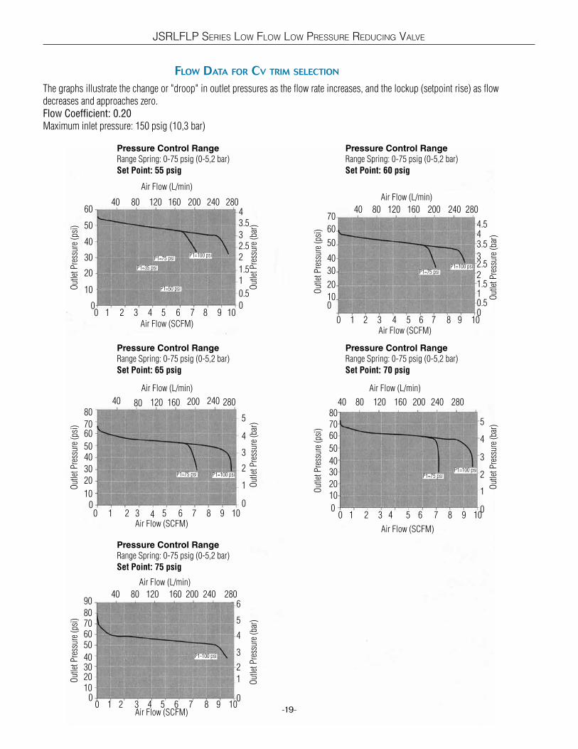
The graphs illustrate the change or "droop" in outlet pressures as the flow rate increases, and the lockup (setpoint rise) as flow decreases and approaches zero.Flow Coefficient: 0.20
Maximum inlet pressure: 150 psig (10,3 bar)
Pressure Control Range
Range Spring: 0-75 psig (0-5,2 bar)
Set Point: 75 psig
Pressure Control Range
Range Spring: 0-75 psig (0-5,2 bar)
Set Point: 65 psig
Pressure Control Range
Range Spring: 0-75 psig (0-5,2 bar)
Set Point: 55 psig
Pressure Control Range
Range Spring: 0-75 psig (0-5,2 bar)
Set Point: 60 psig
Pressure Control Range
Range Spring: 0-75 psig (0-5,2 bar)
Set Point: 70 psig
0
1
0
2
3
5
4
62001208040
80
90
706050
40302010
0
0 1 4 7
1
0
2
3
4
5
2402001208080
70
5040
20
100
0 5 8 9
1
0
1.5
2
1601208040
50
40
30
20
10
010
60
0.5
00
1
3
4
5
20
80
10
0
2
60
30
0
2.5
1.5
50
40
30
20
60
704.5
Out
let P
ress
ure
(psi
)O
utle
t Pre
ssur
e (p
si)
Out
let P
ress
ure
(psi
)
Out
let P
ress
ure
(psi
)O
utle
t Pre
ssur
e (p
si)
Out
let P
ress
ure
(bar
)O
utle
t Pre
ssur
e (b
ar)
Out
let P
ress
ure
(bar
)O
utle
t Pre
ssur
e (b
ar)
Out
let P
ress
ure
(bar
)
Air Flow (L/min)
Air Flow (L/min) Air Flow (L/min)
Air Flow (L/min)Air Flow (L/min)
Air Flow (SCFM)
Air Flow (SCFM)Air Flow (SCFM)
Air Flow (SCFM)Air Flow (SCFM)
P1=35 psi
P1=50 psi
P1=75 psiP1=100 psi
160
200
40
30
60
100 0.5
70
40
50
240 280
762 431
280160
2 3 5 6 8 9 10
240 280
P1=75 psi P1=100 psi
1 6 9 102 3 4 5 7 8
1601208040 200 240 280
0 5 8 1062 431 7 9
40 280160 24020012080
1 4 72 3 5 6 8 9 10
P1-100 psi
P1=75 psiP1=100 psi
P1=75 psiP1=100 psi
2.53
43.5
43.5
3
2
1
JSRLFLP SERIES LOW FLOW LOW PRESSURE REDUCING VALVE

JSRLFLP SERIES LOW FLOW LOW PRESSURE REDUCING VALVE
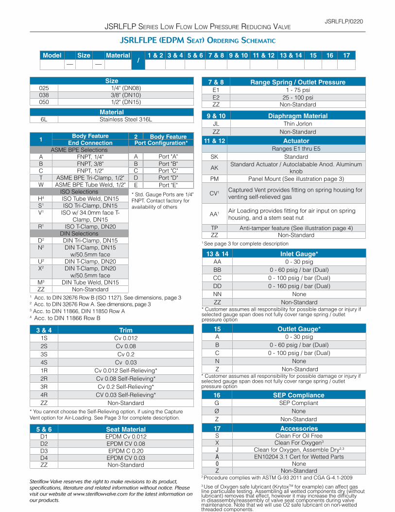
JsrlFlp orDering scHematic (see pg 22 For JsrlFlpe (epDm seat) orDering scHematic)
Model Size Material/
1 & 2 3 & 4 5 & 6 7 & 8 9 & 10 11 & 12 13 & 14 15 16 17
— —
ModelJSRLFLP Low Flow Low Pressure Reducing Valve
Size025 1/4" (DN08)038 3/8" (DN10)050 1/2" (DN15)
Material6L ASTM A479, 316L
1Body Feature
End Connection
ASME BPE SelectionsA FNPT, 1/4"B FNPT, 3/8"C FNPT, 1/2"T ASME BPE Tri-Clamp, 1/2"W ASME BPE Tube Weld, 1/2"
ISO SelectionsH4 ISO Tube Weld, DN15S1 ISO Tri-Clamp, DN15V1 ISO w/ 34.0mm face T-
Clamp, DN15R1 ISO T-Clamp, DN20
DIN SelectionsD2 DIN Tri-Clamp, DN15N2 DIN T-Clamp, DN15
w/50.5mm faceU2 DIN T-Clamp, DN20X2 DIN T-Clamp, DN20
w/50.5mm faceM3 DIN Tube Weld, DN15ZZ Non-Standard
1 Acc. to DIN 32676 Row B (ISO 1127). See dimensions, page 32 Acc. to DIN 32676 Row A. See dimensions, page 33 Acc. to DIN 11866, DIN 11850 Row A 4 Acc. to DIN 11866 Row B
3 & 4 Trim1S Cv 0.012 (Kv 0,010)
4S* Cv 0.03 (Kv 0,026)
2S Cv 0.08 (Kv 0,069)
3S Cv 0.2 (Kv 0,173)
1R Cv 0.012 Self-Relieving**
4R* CV 0.03 Self-Relieving**
2R Cv 0.08 Self-Relieving**
3R Cv 0.2 Self-Relieving**
ZZ Non-Standard
* Though out of sequence, "4S" and "4R" are the correct order codes
for Cv 0.03
** You cannot choose the Self-Relieving option, if using the Capture
Vent option for Air-Loading. See Page 3 for complete description.
5 & 6 Seat Material - FDA & USP Class VIT1 PTFE Cv 0.012 P2 PEEK Cv 0.08
T2 PTFE Cv 0.08 P3 PEEK Cv 0.2
T3 PTFE Cv 0.2 P4 PEEK Cv 0.03
T4 PTFE Cv 0.03ZZ Non-Standard
P1 PEEK Cv 0.012
-20-
2 Body FeaturePort Configuration*
A Port "A"
B Port "B"
C Port "C"
D Port "D"E Port "E"
* Std. Gauge Ports are 1/4"
FNPT. Contact factory for
availability of others
11 & 12 ActuatorRanges E1 thru E5
SK Standard
CV1 Captured Vent provides fitting on spring housing for
venting self-relieved gas
AA1 Air Loading provides fitting for air input on spring
housing, and a stem seat nut
PM Panel Mount
TP Anti-tamper feature (See illustration page 4)
AK Anod. Alum.
ZZ Non-Standard
13 & 14 Inlet Gauge*AA 0 - 30 psi / bar (Dual)
BB 0 - 60 psig / bar (Dual)
CC 0 - 100 psig / bar (Dual)
DD 0 - 160 psig / bar (Dual)
NN None
ZZ Non-Standard
7 & 8 Range Spring / Outlet PressureE1 1 - 75 psi
E2 25 - 100 psi
ZZ Non-Standard
9 & 10 Diaphragm MaterialJL JorlonTM PTFE, FDA & USP Class VI
ZZ Non-Standard
1 See page 3 for complete description
15 Outlet Gauge*
A 0 - 30 psig/bar (Dual)
B 0 - 60 psig / bar (Dual)
C 0 - 100 psig / bar (Dual)
N None
Z Non-Standard
16 SEP ComplianceG SEP Compliant
Ø None
Z Non-Standard
* Customer assumes all responsibility for possible damage or injury if selected gauge span does not fully cover range spring / outlet pressure option
* Customer assumes all responsibility for possible damage or injury if selected gauge span does not fully cover range spring / outlet pressure option
Continued on next page...

2 Procedure complies with ASTM G-93 2011 and CGA G-4.1-2009
3 Use of Oxygen safe lubricant (KrytoxTM for example) can affect gas
line particulate testing. Assembling all wetted components dry
(without lubricant) removes that effect, however it may increase the
difficulty in disassembly/reassembly of valve seat components during
valve maintenance. Note that we will use O2 safe lubricant on non-
wetted threaded components.
JSRLFLP SERIES LOW FLOW LOW PRESSURE REDUCING VALVE
JsrlFlp orDering scHematic (cont. pg 22 For JsrlFlpe (epDm seat) orDering scHematic)
Model Size Material/
1 & 2 3 & 4 5 & 6 7 & 8 9 & 10 11 & 12 13 & 14 15 16 17
— —
-21-
17 AccessoriesS Clean For Oil Free
X Clean For Oxygen3
J Clean for Oxygen, Assemble Dry2,3
A EN10204 3.1 Cert for Wetted Parts
Ø None
Z Non-Standard
JSRLFLP/0220
Steriflow Valve reserves the right to make revisions to its product,
specifications, literature and related information without notice. Please
visit our website at www.steriflowvalve.com for the latest information on
our products.
JSRLFLP SERIES LOW FLOW LOW PRESSURE REDUCING VALVE
JsrlFlpe (eDpm seat) orDering scHematic
Model Size Material/
1 & 2 3 & 4 5 & 6 7 & 8 9 & 10 11 & 12 13 & 14 15 16 17
— —
2 Body FeaturePort Configuration*
A Port "A"
B Port "B"C Port "C"
D Port "D"
E Port "E"
* Std. Gauge Ports are 1/4"
FNPT. Contact factory for
availability of others
11 & 12 ActuatorRanges E1 thru E5
SK Standard
AKStandard Actuator / Autoclabable Anod. Aluminum
knob
PM Panel Mount (See illustration page 3)
CV1 Captured Vent provides fitting on spring housing for
venting self-relieved gas
AA1 Air Loading provides fitting for air input on spring
housing, and a stem seat nut
TP Anti-tamper feature (See illustration page 4)ZZ Non-Standard
7 & 8 Range Spring / Outlet PressureE1 1 - 75 psi
E2 25 - 100 psiZZ Non-Standard
9 & 10 Diaphragm MaterialJL Thin Jorlon
ZZ Non-Standard
2 Procedure complies with ASTM G-93 2011 and CGA G-4.1-2009
3 Use of Oxygen safe lubricant (KrytoxTM for example) can affect gas line particulate testing. Assembling all wetted components dry (without lubricant) removes that effect, however it may increase the difficulty in disassembly/reassembly of valve seat components during valve maintenance. Note that we will use O2 safe lubricant on non-wetted threaded components.
Size025 1/4" (DN08)038 3/8" (DN10)050 1/2" (DN15)
Material6L Stainless Steel 316L
1Body Feature
End Connection
ASME BPE SelectionsA FNPT, 1/4"B FNPT, 3/8"C FNPT, 1/2"T ASME BPE Tri-Clamp, 1/2"W ASME BPE Tube Weld, 1/2"
ISO SelectionsH4 ISO Tube Weld, DN15S1 ISO Tri-Clamp, DN15V1 ISO w/ 34.0mm face T-
Clamp, DN15R1 ISO T-Clamp, DN20
DIN SelectionsD2 DIN Tri-Clamp, DN15N2 DIN T-Clamp, DN15
w/50.5mm faceU2 DIN T-Clamp, DN20X2 DIN T-Clamp, DN20
w/50.5mm faceM3 DIN Tube Weld, DN15ZZ Non-Standard
1 Acc. to DIN 32676 Row B (ISO 1127). See dimensions, page 32 Acc. to DIN 32676 Row A. See dimensions, page 33 Acc. to DIN 11866, DIN 11850 Row A 4 Acc. to DIN 11866 Row B
3 & 4 Trim1S Cv 0.012
2S Cv 0.08
3S Cv 0.2
4S Cv 0.03
1R Cv 0.012 Self-Relieving*
2R Cv 0.08 Self-Relieving*
3R Cv 0.2 Self-Relieving*
4R CV 0.03 Self-Relieving*
ZZ Non-Standard
* You cannot choose the Self-Relieving option, if using the Capture
Vent option for Air-Loading. See Page 3 for complete description.
5 & 6 Seat Material D1 EPDM Cv 0.012
D2 EPDM CV 0.08
D3 EPDM C 0.20
D4 EPDM CV 0.03ZZ Non-Standard
1 See page 3 for complete description
13 & 14 Inlet Gauge*AA 0 - 30 psig
BB 0 - 60 psig / bar (Dual)
CC 0 - 100 psig / bar (Dual)
DD 0 - 160 psig / bar (Dual)
NN None
ZZ Non-Standard
15 Outlet Gauge*A 0 - 30 psig
B 0 - 60 psig / bar (Dual)
C 0 - 100 psig / bar (Dual)
N None
Z Non-Standard
16 SEP ComplianceG SEP Compliant
Ø None
Z Non-Standard
17 AccessoriesS Clean For Oil Free
X Clean For Oxygen3
J Clean for Oxygen, Assemble Dry2,3
A EN10204 3.1 Cert for Wetted Parts
0 None
Z Non-Standard
* Customer assumes all responsibility for possible damage or injury if selected gauge span does not fully cover range spring / outlet pressure option
* Customer assumes all responsibility for possible damage or injury if selected gauge span does not fully cover range spring / outlet pressure option