Embed Size (px)
Citation preview

Journal of Sustainable Architecture and Civil Engineering 2019/1/2452
*Corresponding author: [email protected]
Low Energy Consumption Façade Pilot Project
Received 2018/12/09
Accepted after revision 2019/02/13
Journal of Sustainable Architecture and Civil EngineeringVol. 1 / No. 24 / 2019pp. 52-60DOI 10.5755/j01.sace.24.1.22170
Low Energy Consumption Façade Pilot Project
JSACE 1/24
http://dx.doi.org/10.5755/j01.sace.24.1.22170
Karlis Bumanis, Karlis Pugovics*Forest and Wood Research and Development Institute, Latvia
Introduction
Methods
Retrofitting existing buildings with prefabricated insulation panels provides not only considerably faster construction rates, greater insulation layer thicknesses, but also more finishing options and optimal window placement, when compared to traditional method for retrofitting façades. Considering the variety of buildings in need of renovation, more knowledge of implementation of this type of renovation is of an great importance both for contractors and future manufacturers. A pilot project, retrofitting of a facede, made in 1970’s with an area of approximatelt 135 m2 was done and equipped with a variety of sensors in order to provide insight for the performance of the insulation panels.
Keywords: façade, energy efficiency, renovation, timber-based element system.
Retrofitting existing buildings is a mayor concern within building sector, however current building stock renewal rates in Europe are around 1…1.5% a year (EC, 2010), the potential for faster and more effective means of retrofitting existing building stock is obvious.
Current method of façade retrofitting with additional heat insulation is time consuming and does not always prove the desired efficiency levels, also the options for using different finishing solu-tions for facades is limited, thus rendering often poor aesthetic qualities for the retrofitted facades.
Since prefabricated timber-based panel system provided more flexibility not only in finishing and insulation options, but also in production planning (Jensen. et. al., 2012). Also, considering the fact, that other pilot projects have proven the transferability of the principles of timber frame building for prefabricated timber insulation panels (Lattke F. et. al., 2011), existing manufacturers in Latvia have a great potential for manufacturing prefabricated timber-based insulation panels.
The goal of this project was to create pilot research object based on experiences acquired mainly from international project “TES (Timber Element System) Energy Façade” which studied timber based element system for improving energy efficiency of building envelope mainly for renovation projects to monitor its performance in longer run and exposure to the real service conditions.
Existing facadeThe building in question is a two-storey university building, built in 1970’s from hollow clay bricks with a total area of approximately 135 m2.
The façade had three major aspects that caused additional problem solving during the de-sign phase, first being brick and concrete window casings around each of the 10 windows (see Fig. 1), second – reinforced concrete reinforcing elements constructed later in order to support testing equipement and third being an open gas line protruding about 300 mm from the existing façade.
53Journal of Sustainable Architecture and Civil Engineering 2019/1/24
Design approachTaking into account interna-tional experience and prac-tical considerations, a de-cision to design the panels based upon 3D scan mea-surements was made early on in the design process. 3D model, based upon data from the point cloud (see Fig. 2), was used as a basis for dimensions.
Design process was done in 3D, using CAD software, creating a 3D model of the panels, insulation materi-al, connections, windows and cladding, ensuring pre-cision both in dimensions and material quantities. For bigger projects, work using BIM solutions is a favour-able condition, however, due to scale of this project and competences of involved partners, this solution was not extensively used.
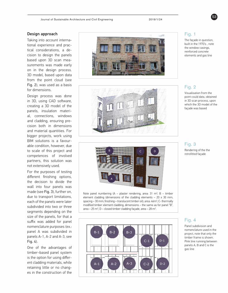
For the purposes of testing different finishing options, the decision to divide the wall into four panels was made (see Fig. 3), further on, due to transport limitations, each of the panels were later subdivided into two or three segments depending on the size of the panels, for that a suffix was added for panel nomenclature purposes (ex.: panel A was subdivided in panels A-1, A-2 and A-3, see Fig. 4).
One of the advantages of timber–based panel system is the option for using differ-ent cladding materials, while retaining little or no chang-es in the construction of the
Fig. 1The façade in question, built in the 1970’s , note the window casings, reinforced concrete elements and gas line
1. Forum Wood Building Baltic 2019
Title | First name and surname
2
Figure 1 The façade in question, built in the 1970’s , note the window casings, reinforced concrete elements and gas line.
2.2. Design approach Taking into account international experience and practical considerations, a decision to design the panels based upon 3D scan measurements was made early on in the design process. 3D model, based upon data from the point cloud (see Figure 2), was used as a basis for dimensions.
Figure 2 visualisation from the point could data, obtained in 3D scan process, upon which the 3D model of the façade was based. Design process was done in 3D, using CAD software, creating a 3D model of the panels, insulation material, connections, windows and cladding, ensuring precision both in dimensions and material quantities. For bigger projects, work using BIM solutions is a favourable condition, however, due to scale of this project and competences of involved partners, this solution was not extensively used. For the purposes of testing different finishing options, the decision to divide the wall into four panels was made (see Figure 3), further on, due to transport limitations, each of the panels were later subdivided into two or three segments depending on the size of the panels, for that a suffix was added for panel nomenclature purposes (ex.: panel A was subdivided in panels A-1, A-2 and A-3, see Figure 4).
Fig. 4Panel subdivision and nomenclature used in the project, note that only the timber frame is shown. Pink line running between panels A, B and C is the gas line
Fig. 2 Visualisation from the point could data, obtained in 3D scan process, upon which the 3D model of the façade was based
1. Forum Wood Building Baltic 2019
Title | First name and surname
2
Figure 1 The façade in question, built in the 1970’s , note the window casings, reinforced concrete elements and gas line.
2.2. Design approach Taking into account international experience and practical considerations, a decision to design the panels based upon 3D scan measurements was made early on in the design process. 3D model, based upon data from the point cloud (see Figure 2), was used as a basis for dimensions.
Figure 2 visualisation from the point could data, obtained in 3D scan process, upon which the 3D model of the façade was based. Design process was done in 3D, using CAD software, creating a 3D model of the panels, insulation material, connections, windows and cladding, ensuring precision both in dimensions and material quantities. For bigger projects, work using BIM solutions is a favourable condition, however, due to scale of this project and competences of involved partners, this solution was not extensively used. For the purposes of testing different finishing options, the decision to divide the wall into four panels was made (see Figure 3), further on, due to transport limitations, each of the panels were later subdivided into two or three segments depending on the size of the panels, for that a suffix was added for panel nomenclature purposes (ex.: panel A was subdivided in panels A-1, A-2 and A-3, see Figure 4).
1. Forum Wood Building Baltic 2019
Title | First name and surname
3
Figure 3 Rendering of the the retrofitted façade. Note panel numbering (A – plaster rendering, area: 31 m2; B – timber element cladding (dimensions of the cladding elements – 20 x 30 mm, spacing – 30 mm; finishing – translucent timber oil), area: 46m2; C- thermally modified timber element cladding, dimensions – the same as for panel “B”, area – 25 m2; D – closed timber cladding façade, area – 28 m2.
Figure 4 Panel subdivision and nomenclature used in the project, note that only the timber frame is shown. Pink line running between panels A, B and C is the gas line. One of the advantages of timber–based panel system is the option for using different cladding materials, while retaining little or no changes in the construction of the panel. For the purposes of this project, two basic panel designs were used: one for plaster rendering, second – for timber cladding solutions (see Figure 5).
A
B C D
B-1 B-2 B-3
A-1 A-2 A-3
C-1
C-2
D-1
D-2
Note panel numbering (A – plaster rendering, area: 31 m2; B – timber element cladding (dimensions of the cladding elements – 20 x 30 mm, spacing – 30 mm; finishing – translucent timber oil), area: 46m2; C- thermally modified timber element cladding, dimensions – the same as for panel “B”, area – 25 m2; D – closed timber cladding façade, area – 28 m2.
1. Forum Wood Building Baltic 2019
Title | First name and surname
3
Figure 3 Rendering of the the retrofitted façade. Note panel numbering (A – plaster rendering, area: 31 m2; B – timber element cladding (dimensions of the cladding elements – 20 x 30 mm, spacing – 30 mm; finishing – translucent timber oil), area: 46m2; C- thermally modified timber element cladding, dimensions – the same as for panel “B”, area – 25 m2; D – closed timber cladding façade, area – 28 m2.
Figure 4 Panel subdivision and nomenclature used in the project, note that only the timber frame is shown. Pink line running between panels A, B and C is the gas line. One of the advantages of timber–based panel system is the option for using different cladding materials, while retaining little or no changes in the construction of the panel. For the purposes of this project, two basic panel designs were used: one for plaster rendering, second – for timber cladding solutions (see Figure 5).
A
B C D
B-1 B-2 B-3
A-1 A-2 A-3
C-1
C-2
D-1
D-2
Fig. 3 Rendering of the the retrofitted façade

Journal of Sustainable Architecture and Civil Engineering 2019/1/2454
Fig. 5Designs for
panels
1. Forum Wood Building Baltic 2019
Title | First name and surname
4
Figure 5 Designs for panels A – with plaster rendering finish (used in panel A); B – with different cladding options (used for panels B, C and D), the structure of the panels is as following, for panel type “A” – compensation layer, wood fibre plate, timber frame, filled with rockwool, plasterboard layer, additional insulation layer and plaster rendering, this structure results in thermal transmittance value of 0.123 W/m2K, for panel type “B” the structure is: compensation layer, wood fibre plate, timber frame, filled with rockwool, additional insulation layer with wind protection and timber cladding, this structure resulted in thermal transmittance value of 0.125 W/m2K. Due to the fact, that decision to retain protrusions in the existing façade was made early on, cavities in panels had to be manufactured in order to accommodate them, this was done as shown on Figure 6.
Figure 6 Cross sectional cut of the panels, showing cavities, designed to accommodate concrete reinforcement and window casings (A) and just the window casing: a – window sill; b – window casing; c – concrete reinforcement. A running gas line was a major challenge during the design process. In order to achieve minimal changes in the existing façade, thus reducing construction time and legal process involved in retrofitting the existing wall, the decision not to change the line in any way was made. The panels were designed around the gas line and a trench between panels A, B and C was left in order to do so, to minimize heat loses, back side of the trench was lined with heat insulation. The gas line was covered with ventilated and rapidly removable cladding frame for reducing the risk of potential gas pocket formation and for providing a fast way for gas line maintenance, cross sectional view of gas line trench is given in Figure 7.
A B
A – with plaster rendering finish (used in panel A); B – with different cladding options (used for panels B, C and D), the structure of the panels is as following, for panel type “A” – compensation layer, wood fibre plate, timber frame, filled with rockwool, plasterboard layer, additional insulation layer and plaster rendering, this structure results in thermal transmittance value of 0.123 W/m2K, for panel type “B” the structure is: compensation layer, wood fibre plate, timber frame, filled with rockwool, additional insulation layer with wind protection and timber cladding, this structure resulted in thermal transmittance value of 0.125 W/m2K.
panel. For the purposes of this project, two basic panel designs were used: one for plaster render-ing, second – for timber cladding solutions (see Fig. 5).
Due to the fact, that decision to retain protrusions in the existing façade was made early on, cav-ities in panels had to be manufactured in order to accommodate them, this was done as shown on Fig. 6.
Fig. 6Cross sectional cut of
the panels, showing cavities, designed to
accommodate concrete reinforcement and
window casings (A) and just the window casing:
a – window sill; b – window casing;
c – concrete reinforcement
A running gas line was a major challenge during the design process. In order to achieve minimal changes in the existing façade, thus reducing construction time and legal process involved in retrofitting the existing wall, the decision not to change the line in any way was made. The panels were designed around the gas line and a trench between panels A, B and C was left in order to
1. Forum Wood Building Baltic 2019
Title | First name and surname
4
Figure 5 Designs for panels A – with plaster rendering finish (used in panel A); B – with different cladding options (used for panels B, C and D), the structure of the panels is as following, for panel type “A” – compensation layer, wood fibre plate, timber frame, filled with rockwool, plasterboard layer, additional insulation layer and plaster rendering, this structure results in thermal transmittance value of 0.123 W/m2K, for panel type “B” the structure is: compensation layer, wood fibre plate, timber frame, filled with rockwool, additional insulation layer with wind protection and timber cladding, this structure resulted in thermal transmittance value of 0.125 W/m2K. Due to the fact, that decision to retain protrusions in the existing façade was made early on, cavities in panels had to be manufactured in order to accommodate them, this was done as shown on Figure 6.
Figure 6 Cross sectional cut of the panels, showing cavities, designed to accommodate concrete reinforcement and window casings (A) and just the window casing: a – window sill; b – window casing; c – concrete reinforcement. A running gas line was a major challenge during the design process. In order to achieve minimal changes in the existing façade, thus reducing construction time and legal process involved in retrofitting the existing wall, the decision not to change the line in any way was made. The panels were designed around the gas line and a trench between panels A, B and C was left in order to do so, to minimize heat loses, back side of the trench was lined with heat insulation. The gas line was covered with ventilated and rapidly removable cladding frame for reducing the risk of potential gas pocket formation and for providing a fast way for gas line maintenance, cross sectional view of gas line trench is given in Figure 7.
A B

55Journal of Sustainable Architecture and Civil Engineering 2019/1/24
do so, to minimize heat loses, back side of the trench was lined with heat insulation. The gas line was covered with ventilated and rap-idly removable cladding frame for reducing the risk of potential gas pocket formation and for provid-ing a fast way for gas line mainte-nance, cross sectional view of gas line trench is given in Fig. 7.
WindowsIn order to achieve optimal place-ment of the windows within the cross-section of the façade and to accommodate window casings, windows were placed in win-dow sills, placed outwards form the panel as given in Fig. 8 and Fig. 6.
Double-paned windows with tim-ber frames (profile IV90, frame thickness – 90 mm, thermal trans-mittance under 1.0 W/m2K).
Insulation materialFor all panels, three sheets of in-sulation material were used (in order from inside outwards): com-pensation layer with thickness of 30 mm, main insulation layer with thickness of 200 mm and additional layer with wind stop-ping membrane with thickness of 50 mm, covering all of the panel. Rendering of the cross-section of the panel, showing insulation lay-ers is given in Fig. 5, detailed in-formation on insulation materials is given in Fig. 5.
Panel mounting to the existing façadeFor this project, a mixed type of mounting was used: panel A was 100% storey-wise mounted, while for panels B, C and D a combination of storey-wise and hanging solu-tion was used as seen in Fig. 9.
Fig. 7 Cross-sectional cut, showing the gas line trench, with additional insulation material and cladding over the gas line visible
Fig. 8Window in the near-completed façade, outward placement is clearly visible
1. Forum Wood Building Baltic 2019
Title | First name and surname
5
Figure 7 Cross-sectional cut, showing the gas line trench, with additional insulation material and cladding over the gas line visible.
2.3. Windows In order to achieve optimal placement of the windows within the cross-section of the façade and to accommodate window casings, windows were placed in window sills, placed outwards form the panel as given in Figure 8 and Figure 6.
Figure 8 Window in the near-completed façade, outward placement is clearly visible. Double-paned windows with timber frames (profile IV90, frame thickness – 90 mm, thermal transmittance under 1.0 W/m2K).
1. Forum Wood Building Baltic 2019
Title | First name and surname
6
2.4. Insulation material For all panels, three sheets of insulation material were used (in order from inside outwards): compensation layer with thickness of 30 mm, main insulation layer with thickness of 200 mm and additional layer with wind stopping membrane with thickness of 50 mm, covering all of the panel. Rendering of the cross-section of the panel, showing insulation layers is given in Figure 5, detailed information on insulation materials is given in Figure 5.
2.5. Panel mounting to the existing façade. For this project, a mixed type of mounting was used: panel A was 100% storey-wise mounted, while for panels B, C and D a combination of storey-wise and hanging solution was used as seen in Figure 9.
Figure 9 Panel mounting solutions. Right – solution for panels A and B, left – panels C and D. Red line represents position of fixing elements.
2.6. Monitoring For the purposes of this study, two types of monitoring were done: real-time monitoring of different atmospheric parameters and visual monitoring of the cladding elements. Real-time monitoring of atmospheric conditions was done for two basic panel types: plaster rendering finished panel A and timber cladding finished panel B, placement of measurement devices is given in Figure 10.
Fig. 9 Panel mounting solutions. Right – solution for panels A and B, left – panels C and D. Red line represents position of fixing elements

Journal of Sustainable Architecture and Civil Engineering 2019/1/2456
MonitoringFor the purposes of this study, two types of monitoring were done: real-time monitoring of differ-ent atmospheric parameters and visual monitoring of the cladding elements.
Real-time monitoring of atmospheric conditions was done for two basic panel types: plaster ren-dering finished panel A and timber cladding finished panel B, placement of measurement devices is given in Fig. 10.
Figure 10Placement of
measurement devices
1. Forum Wood Building Baltic 2019
Title | First name and surname
6
2.4. Insulation material For all panels, three sheets of insulation material were used (in order from inside outwards): compensation layer with thickness of 30 mm, main insulation layer with thickness of 200 mm and additional layer with wind stopping membrane with thickness of 50 mm, covering all of the panel. Rendering of the cross-section of the panel, showing insulation layers is given in Figure 5, detailed information on insulation materials is given in Figure 5.
2.5. Panel mounting to the existing façade. For this project, a mixed type of mounting was used: panel A was 100% storey-wise mounted, while for panels B, C and D a combination of storey-wise and hanging solution was used as seen in Figure 9.
Figure 9 Panel mounting solutions. Right – solution for panels A and B, left – panels C and D. Red line represents position of fixing elements.
2.6. Monitoring For the purposes of this study, two types of monitoring were done: real-time monitoring of different atmospheric parameters and visual monitoring of the cladding elements. Real-time monitoring of atmospheric conditions was done for two basic panel types: plaster rendering finished panel A and timber cladding finished panel B, placement of measurement devices is given in Figure 10.
a – measurement point inside the building; b – measurement point on the interior wall; c – measurement pint between the panel and the old wall; d – measurement point within the panel; e – measurement point on the outside of the panel; f – measurement point between the panel and the cladding; e – measurement point on the outside of the panel
Types of measurement devices used, are given in Fig. 11.
Fig. 11Types of
measurement devices
1. Forum Wood Building Baltic 2019
Title | First name and surname
7
Figure 10 placement of measurement devices: a – measurement point inside the building; b – measurement point on the interior wall; c – measurement pint between the panel and the old wall; d – measurement point within the panel; e – measurement point on the outside of the panel; f – measurement point between the panel and the cladding; e – measurement point on the outside of the panel. Types of measurement devices used, are given in Figure 12.
Figure 12 Types of measurement devices: 1, 3, 4, 5, 7 – air temperature and relative humidity sensor; 2, 8 – surface temperature sensor; 6 – material temperature sensor. Data from all measurement sensors are collected in real-time and accessible via internet as seen in Figure 13.
Figure 13 Real-time data monitoring of the façade, accessed via internet. Visual monitoring of cladding elements is done by means of photo fixation in order to spot delamination and fungal damage originating from façade being exposed to elements.
Data from all measurement sensors are collected in real-time and accessible via internet as seen in Fig. 12.
1. Forum Wood Building Baltic 2019
Title | First name and surname
7
Figure 10 placement of measurement devices: a – measurement point inside the building; b – measurement point on the interior wall; c – measurement pint between the panel and the old wall; d – measurement point within the panel; e – measurement point on the outside of the panel; f – measurement point between the panel and the cladding; e – measurement point on the outside of the panel. Types of measurement devices used, are given in Figure 12.
Figure 12 Types of measurement devices: 1, 3, 4, 5, 7 – air temperature and relative humidity sensor; 2, 8 – surface temperature sensor; 6 – material temperature sensor. Data from all measurement sensors are collected in real-time and accessible via internet as seen in Figure 13.
Figure 13 Real-time data monitoring of the façade, accessed via internet. Visual monitoring of cladding elements is done by means of photo fixation in order to spot delamination and fungal damage originating from façade being exposed to elements.
Fig. 12Real-time data
monitoring of the façade, accessed via
internet
1, 3, 4, 5, 7 – air temperature and relative humidity sensor; 2, 8 – surface temperature sensor; 6 – material temperature sensor.

57Journal of Sustainable Architecture and Civil Engineering 2019/1/24
Visual monitoring of cladding elements is done by means of photo fixation in order to spot delam-ination and fungal damage originating from façade being exposed to elements.
Figure 13Data monitoring results from June, 2015 till June, 2016
Results and discussion
Real-time monitoringResults for the real-time monitoring are given in Fig. 13, 14 and 15.
Figure 14Data monitoring results from June, 2016 till June, 2017, note, that at this point 06ttf sensor malfunctioned and was not able to provide reliable data
1. Forum Wood Building Baltic 2019
Title | First name and surname
8
3. Results and discussion 3.1. Real-time monitoring Results for the real-time monitoring are given in Figure 14, 15 and 16.
Figure 15 Data monitoring results from June, 2015 till June, 2016. Nomenclature for the sensors is as following: first two numbers indicate the number of the sensor (see Figure 13), the following two letters denote the type of sensor (hh and th being sensors for temperature and relative humidity, tt – surface temperature), last letter “f” denoted that these sensors are mounted on the façade. Note data gaps at around third segment from left on the horizontal axis and incorrect data from 05hhf and 03hhf sensors due to equpement malfunction.
Figure 16 Data monitoring results from June, 2016 till June, 2017, note, that at this point 06ttf sensor malfunctioned and was not able to provide reliable data.
Nomenclature for the sensors is as following: first two numbers indicate the number of the sensor (see Fig. 13), the following two letters denote the type of sensor (hh and th being sensors for temperature and relative humidity, tt – surface temperature), last letter “f” denoted that these sensors are mounted on the façade. Note data gaps at around third segment from left on the horizontal axis and incorrect data from 05hhf and 03hhf sensors due to equpement malfunction

Journal of Sustainable Architecture and Civil Engineering 2019/1/2458
Fig. 15Data monitoring
results from June, 2017 till June, 2018,
note, that at this point 06ttf sensor
malfunctioned and was not able to
provide reliable data
1. Forum Wood Building Baltic 2019
Title | First name and surname
9
Figure 17 Data monitoring results from June, 2017 till June, 2018, note, that at this point 06ttf sensor malfunctioned and was not able to provide reliable data.
3.2. Visual monitoring After three years of exposure to the environment, the following defects were observed:
Fungal development on thermally modified cladding (see Figure 17).
Figure 17 Fungal development at around 1400 mm from ground level as observed on November, 2018.
Discoloration around fixing element on thermally modified timber cladding (see Figure 18)
Visual monitoringAfter three years of exposure to the environment, the following defects were observed:
_ Fungal development on thermally modified cladding (see Fig. 16).
_ Discoloration around fixing element on thermally modified timber cladding (see Fig. 17)
_ Fungal development and delamination of cladding elements, treated with white, semi-trans-lucent façade paint (see Fig. 18 and 19)
_ Discoloration of thermally modified cladding elements (see Fig. 20).
For plaster rendered panel and unmodified timber cladding no significant damages were observed on November, 2018 other than the noted fungal development and delamination on larger ele-ments, covering corners and panel gaps.
The fungal development in thermally modified cladding elements can be explained with possi-
Fig. 16 Fungal development at around 1400 mm from
ground level as observed on November, 2018
Fig. 17Discoloration around
fixing element on thermally modified timber
cladding as observed on November, 2018
1. Forum Wood Building Baltic 2019
Title | First name and surname
9
Figure 17 Data monitoring results from June, 2017 till June, 2018, note, that at this point 06ttf sensor malfunctioned and was not able to provide reliable data.
3.2. Visual monitoring After three years of exposure to the environment, the following defects were observed:
Fungal development on thermally modified cladding (see Figure 17).
Figure 17 Fungal development at around 1400 mm from ground level as observed on November, 2018.
Discoloration around fixing element on thermally modified timber cladding (see Figure 18)
1. Forum Wood Building Baltic 2019
Title | First name and surname
10
Figure 18 Discoloration around fixing element on thermally modified timber cladding as observed on November, 2018.
Fungal development and delamination of cladding elements, treated with white, semi-translucent façade paint (see Figures 19 and 20)
Figure 19 Fingal development and delamination of timber cladding elements at around 200 mm from ground level as observed on November, 2018.
16 17

59Journal of Sustainable Architecture and Civil Engineering 2019/1/24
Fig. 18Fingal development and delamination of timber cladding elements at around 200 mm from ground level as observed on November, 2018
Fig. 19Delamination of timber cladding element at around 1400 mm from ground level as observed on November, 2018
Fig. 20Discoloration of thermally modified cladding elements is clearly visible, when removing cladding part, covering the gas line as observed on November, 2018, note the lack of discoloration around fixing elements
1. Forum Wood Building Baltic 2019
Title | First name and surname
10
Figure 18 Discoloration around fixing element on thermally modified timber cladding as observed on November, 2018.
Fungal development and delamination of cladding elements, treated with white, semi-translucent façade paint (see Figures 19 and 20)
Figure 19 Fingal development and delamination of timber cladding elements at around 200 mm from ground level as observed on November, 2018.
1. Forum Wood Building Baltic 2019
Title | First name and surname
11
Figure 20 Delamination of timber cladding element at around 1400 mm from ground level as observed on November, 2018.
Discoloration of thermally modified cladding elements (see Figure 21).
Figure 21 Discoloration of thermally modified cladding elements is clearly visible, when removing cladding part, covering the gas line as observed on November, 2018, note the lack of discoloration around fixing elements. For plaster rendered panel and unmodified timber cladding no significant damages were observed on November, 2018 other than the noted fungal development and delamination on larger elements, covering corners and panel gaps. The fungal development in thermally modified cladding elements can be explained with possible shortcoming in the thermal modification process, however more aggressive thermal modification would compromise the structural integrity of the cladding member, thus rendering it unusable in this application, for this a cladding member with greater dimensions should be considered, however this would not be feasible due to economic aspect, so some form of translucent oil treatment should be considered in order to preserve the thermally modified timber cladding elements.
ble shortcoming in the thermal modification process, however more aggressive thermal modification would compromise the structur-al integrity of the cladding member, thus ren-dering it unusable in this application, for this a cladding member with greater dimensions should be considered, however this would not be feasible due to economic aspect, so some form of translucent oil treatment should be considered in order to preserve the thermally modified timber cladding elements.
18 19
20
Delamination of the larger cladding elements, covering corners and panel gaps can mainly be attributed to dimensions of the cladding element, while fungal development in the corner (see Fig. 18) is most likely due to incorrect execution of element fixing – the timber element is touching the metal drainage element, which makes it more susceptible to damage caused by excessive moisture.
ConclusionsRetrofitting of existing building, using timber-based panels can be feasible provided that high-er thermal transmittance properties, more complex architectural solutions and faster assembly time is desired.
Price per square meter of timber-based panels is highly dependent on chosen cladding material, since cladding material constituted around 25% of total panel costs.
After three years of service it is visible, that conditions within the panel and between the panel and existing wall are optimal and no formation of dew point was observed.
Fungal development and discoloration of thermally modified cladding material suggests prob-lems with untreated thermally modified timber caused by factors to be researched further on.
Acknow-ledgment
Research was carried out within the project “Research of wood materials with increased eco-logical value” Investment and Development Agency of Latvia, project No.L-KC-11-0004 co-fi-nanced by the European Union within the project framework of the European Regional Devel-opment Fund.
EC. Energy-Efficient Buildings PPP, Multi-Annu-al Roadmap and Longer Term Strategy; European Commission: Brussels, Belgium, 2010.
Lattke, F., Ott, S., Winter, S.: TES EnergyFacade – Vorfertigung bei der energetischen Sanierung. Bau-technik – Innovative Fassadentechnik, vol. 88(9). Ernst & Sohn Verlag, Berlin.
References

Journal of Sustainable Architecture and Civil Engineering 2019/1/2460
Jensen, P., Olofsson, T., Johnsson, H.: Configuration through the parameterization of building compo-
nents. Automation Construction 23, 1–8 (2012).https://doi.org/10.1016/j.autcon.2011.11.016
KARLIS BUMANIS
Vice director
Forest and wood research and development institute
Main research area
Wood mechanical properties, Biofuels
Address
Dobeles str. 41, Jelgava, LV-3001, LatviaTel. +371 63010605E-mail: [email protected]
KARLIS PUGOVICS
Engineer
Forest and wood research and development institute
Main research area
Timber structures
Address
Dobeles str. 41, Jelgava, LV-3001, LatviaTel. +371 26893016E-mail: [email protected]
About the Authors