Embed Size (px)
Citation preview

JPL Studies in Support of the SWOT Mission
Ernesto RodriguezJPL/CalTech
Washington, October 28, 2007
JPL Internal Investment on SWOT
• JPL “Team-X” end-to-end mission assessment, including cost– Preliminary assessment: no show stoppers, but several risk items
identified• Experiment to determine near-nadir scattering characteristics of
rivers (D. Moller, PI)• Studies to assess feasibility of next-generation radiometer
corrections of wet tropospheric delays (S. Brown)• Internal studies and contract to Ball Aerospace to assess one of
the primary risk areas: power generation with minimal attitudecontrol system disturbance
• JPL will submit an IIP proposal (L-L Fu, PI) to further addressoutstanding technology risk areas


The marriage penalty…• Ocean + land data collection >double required transmit energy• Non-sun synchronous orbit is harder than 6am/6pm sun sync
– Solar panel size must increase to compensate for eclipse time– Optimal solar panel orientation requires continuoius solar panel
rotation about 2 axes, but solar panel rotation disturbs thespacecraft attitude, leading to measurement errors
– Battery size must increase⇒ Need new approach to power generation
• Data collection over land and ocean increases data volume anddownlink rate beyond currently affordable capabilities⇒ Need onboard processing of ocean data to reduce downlink spatial
resolution to 1 km x 1 km• Higher orbit + higher solar panel mass requires a bigger
launcher- Launcher probably in the Delta-II, Ariane class- Minotaur IV or Taurus launch may not be feasible
A joint power-attitude/control strategy
• Solar panel motion can couple directly to the attitudecontrol system knowledge error, leading tosystematic (i.e., not random) height and slope errors⇒An optimal ACS strategy must restrict solar panel motion to
just a few times/orbit• For stationary solar panels, the angle between the
sun and the solar panel must be adjusted as fewtimes per orbit as possible- For a 78 deg inclination orbit, it is best to adjust solar panel
orientation at higher latitudes, since higher latitudes arevisited preferentially

SWOT Mission Solar Array Sizing
• Spacraft assumption: Ball BCP-2000 (used for QuikSCAT, CloudSat,…)• Orbit Parameters
– Altitude: 993 km (not critical)– Inclination: 78˚– Period: 105 minutes– Beta Angle: 0˚ to ±90˚– Eclipse Duration: 0 to 35 minutes– Sun Range (min): 0.983 AU (near winter solstice)– Sun Range (max): 1.016 AU (near summer solstice)
• Loads– Bus: 750W (varies depending on data and telecom requirements)– Payload: 562W
• Vehicle Attitude– Nadir-pointed, maintaining interferometer payload baseline orthogonal to velocity– No sun-nadir (a.k.a., yaw) steering
• Caveats– Thermal behavior of the various options not modeled; could have second-order affects on
sizing analyses– Analyses assume no shadow affects on the solar array at any point in the orbit

SWOT Solar Array Configuration #1Single-Axis Articulation
• Flat panel, trailing bus, conventional solar array technology
• Single-axis articulation, articulate only over polar regions
• Worst-case orbit– Beta angle = 0˚– Eclipse duration = 35 minutes
• Description of operation– Assume conventional stowage and deployment methods– Over polar regions, solar array rotates about the x-axis (velocity vector) to preposition into fixed orientation for optimal power generation during subsequent pole-to-pole pass.– Array off-sun angle reaches 0 degrees as vehicle passes over equator and is near 90 degrees while vehicle is
over polar regions.
• Solar Array capability (raw) meets end of life requirements with 25% margin using two solar panels,each of which is smaller than solar panels considered for the NPOES Preparatory Project (NPP)being built at Ball Aerospace.
• Using conventional solar panel technology, a mass penalty > 200 kg will be incurred.• Potential data loss during panel rotation.• Battery sizing -- 32 Amp-hour sufficient for worst case eclipse; bus can accommodate larger
battery.
S/V bus
Solar array (flat panel, leading &trailing bus, single-axis articulation,S/A angle adjusted only during polar
passes with articulation angleremaining fixed during
pole-to-pole portion of orbit)
nadir
velocity
Solar array

SWOT Array Configuration #2Fixed Differential Orientation, No Articulation
• Two flat panels, trailing bus (beta = 0 to +90) & leading bus (beta = 0 to -90), conventional solar array technology
• Worst-case orbit– Beta angle = 0˚– Eclipse duration = 35 min.
• Panels off-set by fixed angle of XX (ITAR sensitive?), no articulation (XX is the optimal off-set), sun vector bisects the panel off-set angle when beta = 90˚
• Description of operation– Assume conventional stowage and deployment methods– Individual panel off-sun angles vary from XX (ITAR sensitive?) degrees to 90 degrees and above (i.e., back side illuminated) during pole-to-pole passes.
• Solar Array capability (raw) meets end of life requirements with 25% margin using two solar panels, eachof which is about 2x the size of the solar panels considered for the NPOES Preparatory Project (NPP)being built at Ball Aerospace.
• No data loss in incurred at any point in the orbit.• Using conventional solar panels, a total mass penalty > 400 kg will be incurred• Battery sizing -- 32 Amp-hour sufficient for worst case eclipse; bus can accommodate larger battery.
Solar array (two flat panels, leading &trailing bus, non-articulated,
determine optimum angle between panels to maximize power generation)
S/V bus
nadir
velocity
Solar array
notionalviewfrom back
aft array
bus
forwardarray
nadir
SWOT Array Configuration #3Two-Axis Articulation
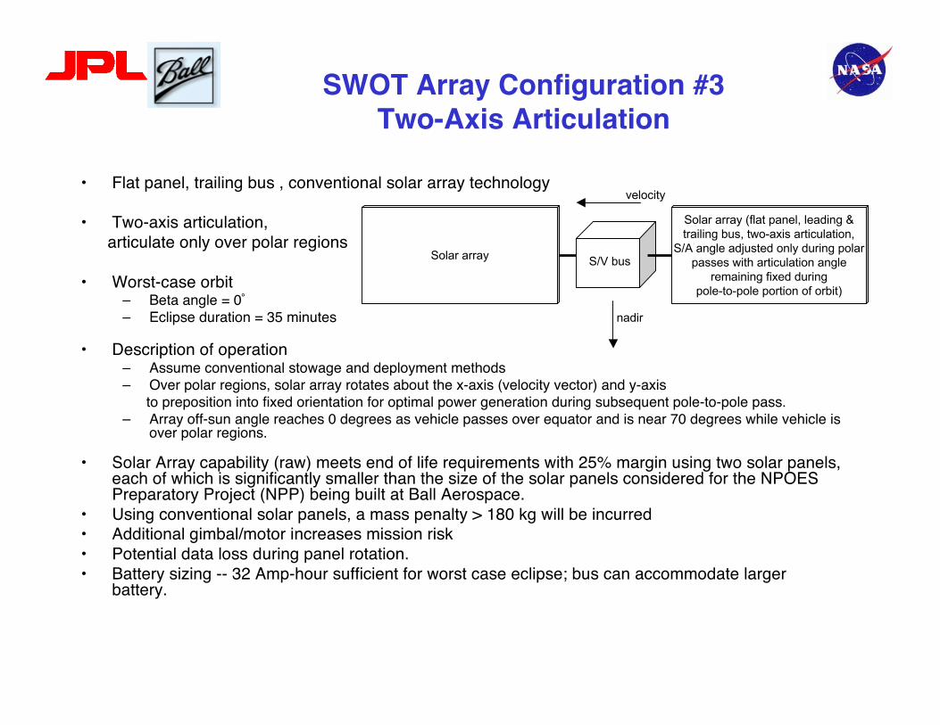
• Flat panel, trailing bus , conventional solar array technology
• Two-axis articulation, articulate only over polar regions
• Worst-case orbit– Beta angle = 0˚– Eclipse duration = 35 minutes
• Description of operation– Assume conventional stowage and deployment methods– Over polar regions, solar array rotates about the x-axis (velocity vector) and y-axis to preposition into fixed orientation for optimal power generation during subsequent pole-to-pole pass.– Array off-sun angle reaches 0 degrees as vehicle passes over equator and is near 70 degrees while vehicle is
over polar regions.
• Solar Array capability (raw) meets end of life requirements with 25% margin using two solar panels,each of which is significantly smaller than the size of the solar panels considered for the NPOESPreparatory Project (NPP) being built at Ball Aerospace.
• Using conventional solar panels, a mass penalty > 180 kg will be incurred• Additional gimbal/motor increases mission risk• Potential data loss during panel rotation.• Battery sizing -- 32 Amp-hour sufficient for worst case eclipse; bus can accommodate larger
battery.
S/V bus
Solar array (flat panel, leading &trailing bus, two-axis articulation,
S/A angle adjusted only during polarpasses with articulation angle
remaining fixed duringpole-to-pole portion of orbit)
nadir
velocity
Solar array


ATK Ultraflex solar panels are being flown as part of the JPLPhoenix Mars lander mission.

S/V bus
nadir
velocity UltraFlex solar array(leading & trailing bus,single-axis articulation,
S/A angle adjustedonly during polar passes
with articulationangle remaining fixed
during pole-to-poleportion of orbit)
UltraFlex solar array
SWOT Solar Array Configuration #4ATK UltraFlex Technology, Single-Axis Articulation
• Flat panel, trailing bus, ATK UltraFlex solar array technology -- significant mass & MOI reduction Heritage: Mars Phoenix, NMP ST-8, & baselined for CEV/Orion
• Single-axis articulation, articulate only over polar regions
• Worst-case orbit– Beta angle = 0˚– Eclipse duration = 35 minutes
• Description of operation– Compact stowage volume and motor-driven deployment w/ staging, unfurling, tensioning, & latching
operations.– Over polar regions, solar array rotates about the x-axis (velocity vector) to preposition into fixed orientation for optimal power generation during subsequent pole-to-pole pass.– Array off-sun angle reaches 0 degrees as vehicle passes over equator and is near 90 degrees while vehicle is
over polar regions.
• Solar Array capability (raw) meets end of life requirements with 25% margin using two solar panels.• Panel area within Ultraflex capabilities.• Using conventional solar panel technology, a mass penalty < ~70 kg will be incurred.• Potential data loss during panel rotation.• Battery sizing -- 32 Amp-hour sufficient for worst case eclipse; bus can accommodate larger
battery.

Spacecraft Bus Accommodates Wide Range ofArticulation Rates for SWOT Solar Arrays
• Typical BCP2000 momentum exchange actuators sufficient ICESat & CloudSat RWAs: XX N-m-s & XX N-m QuickBird II RWAs: XX N-m-s & XX N-m
• Solar Array Articulation Analysis Results -- Angular Momentum Exchanged
Achieving 5-minute data outage produceslarge angular momentum exchange.
Worst casereorientation
scenarios
Case 1: Flat-panel, conventional S/A technology, single-axis articulation 180 degrees about x-axis MOI (kilogram-meters^2) 208 max. ang. accel. (degrees per second^2) 0.028
Case 3: Flat-panel, conventional S/A technology, two-axis articulation 90 degrees about y-axis MOI (kilogram-meters^2) 781 max. ang. accel. (degrees per second^2) 0.007
Case 4: Flat-panel, UltraFlex S/A technology, single-axis articulation 180 degrees about x-axis MOI (kilogram-meters^2) 71 max. ang. accel. (degrees per second^2) 0.081
Articulate above latitude (degrees) 60 65 70 75 77Available articulation time (minutes) 23.2 19.6 15.3 9.3 5.0
Case 1: max. ang. momentum (N-m-s) OK OK OK OK OK
Case 3: max. ang. momentum (N-m-s) OK OK OK OK NO
Case 4: max. ang. momentum (N-m-s) OK OK OK OK OK

Summary
• The SWOT power requirements can be achieved using abalanced configuration using present day buses and a feasibleextension of current solar panel array technology– These requirements are met with minimal impact on the attitude
control system, and with minimal systematic errors• Upcoming Ultraflex solar panel technology looks like a potential
candidate to satisfy both power and weight constraints• The power generation strategy proposed here has concentrated
on the Ball BCP 2000 bus, but could probably be adapted toother medium sized buses
• Further analysis is currently underway to further validate theseconclusions