Embed Size (px)
Citation preview

Journal of Solar Energy Research Updates, 2019, 6, 43-50 43
E-ISSN: 2410-2199/19 © 2019 Zeal Press
Multi-Factorial Comparison for Twenty-Four Distinct Transposition Models for Inclined Surface Solar Irradiance Forecasting, Study Case: Palestine State
Yasser Fathi Nassar1, Samer Yassin Alsadi2,*, Khalid Amer Ali1, Abdalaziz Hassan Yousef1, and Massoud Ali Fakher1
1Mechanical Engineering Department, Engineering and Technology Faculty, Sebha University, Brack, Libya 2Electrical Engineering Department, Faculty of Engineering and Technology, Palestine Technical University, Tulkarm, Palestine
Abstract: This paper presents a practical design of combination solar photovoltaic panel (PV) and an ordinary flat-plate air heating solar collector (FPSC. (The offered collector generated both electrical and thermal power for many applications such as (drying, heating, cooling, etc...). The PV cells are placed in the entrance of the (FPSC), the design avoids the temperature increasing of the PV. In this paper the photovoltaic thermal (PV/T) collector energy analysis were carried out. A mathematical model has been built in order to determine the optimum contribution ratio of the PV cells in the offered collector. The model takes into account the variation of the electrical characteristics with solar radiation and the PV cell's temperature. The obtained results have shown that for a (PV/T) collector of 3m long, the maximum energy extracted from the collector, when the length of the PV panel is 2.4 m and the rest of the collector is ordinary FPSC. Furthermore, the electrical efficiency and the thermal efficiency of the PV/T system was found to be higher than that of the conventional separated systems.
Keywords: Optimum area contribution ratio of PV, PV/T solar collector, Electrical efficiency, Thermal efficiency, PV/T efficiency, Heat transfer coefficients.
1. INTRODUCTION
As any solar system the efficiency of the PV cells increases with increasing the solar radiation, but also brings overheating problem. Since we know that, the power generated from the PV cells decreases when the is determining the optimum contribution of the PV area cell temperature increases, as it illustrated in Figure 1 [1]. Hence, a new technology combining thermal and photovoltaic together in one unit is named photovoltaic - thermal (PV/T) system to produce simultaneously thermal and electrical energy. There are many designs of (PV/T) collectors, important design parameters are identified [2]. In [3] a thorough review of the available literature on photovoltaic/thermal (PV/T) systems is presented. Many researchers discussed R&D aspects of (PV/T) technologies such as air-type [4-6], liquid-type (PV/T) systems [6-8], and even both air and water-type [9], collector design and performance, experimental and theoretical studies and building-integrated installations [10-12]. Besides of all these researches, no one studied the optimum length of the PV cells in the PV/T solar collector. The new hybrid (PV/T) described in this paper is a novel approach to maximize the total efficiency of both thermal and electrical conversion with lower cost compared to traditional hybrid collectors, the objective of this paper *Address correspondence to this author at the Electrical Engineering Department, Faculty of Engineering and Technology, Palestine Technical University-Kadoorie, Tulkarm, Palestine; E-mail: [email protected]
in the solar collector by modelling of the new collector through the determination of temperature for each layer and its instantaneous thermal and electrical efficiency. To achieve this purpose a computer program has been created, the analysis adopted the implicit finite difference technique under real climatic conditions and operation and design parameters recommended by [13].
This paper is further organized as follows: Section 2 describes the construction of the proposed PV/T collector. Section 3 prescribed the mathematical modelling of the PV/T collector. While section 4 demonstrates the obtained results. Finally, section 5 outlines some conclusions drawn fromthe results obtained in the present work.
Figure 1: The effect of the irradiance and cell's temperature on the electrical characteristics of the PV cell.

44 Journal of Solar Energy Research Updates, 2019, Vol. 6 Nassar et al.
2. THE PV/T COLLECTOR CONSTRUCTION
The structure of the offered collector is shown in Figure 2. Every model of solar panel has unique performance characteristics which can be graphically represented in a chart. The graph is called an “I-V curve”, and it refers to the module’s output relationship between current (I) and voltage (V) under prevailing conditions of sunlight and temperature [14]. Using air as a working fluid in the PV/T has many advantage.
Figure 2: The construction of the novel PV/T air collector, the airstream flowing up and down sides the absorber plate (covered-suspended flat-plate solar collector).
3. MATHEMATICAL MODELLING
The heat transfer treatment of this unsteady thermal-electrical problem is not classical specially for the portion of the absorber plate that contained PV cells, because multi-variables involved in the energy
balance (thermal and electrical). Furthermore, the numerical model presented in this work differs from other models in that the convective heat transfer coefficients associate with air flowing through the channels are function in both distance and temperatures of the upper and lower sides of the channel. Figure 3 presents a schematic of heat transfer processes and coefficients over the PV/T collector considered in this study. The model is based on the analysis of the energy balance which includes the photoelectric conversion and the thermal conduction, convection and radiation. The implicit finite difference technique is performed over a differential element having a surface area (width x length) W dx, where dx is a differential element in the x direction (m). After making the following assumptions:
1. Heat transfer is one dimension in the direction of the flow (x);
2. The thermal properties of all collector's components and the air flows are constants;
3. No absorption of solar radiation through the glass cover;
4. No heat losses from the sides of the collector;
5. The view factors between the collector's components and between the collector and the sky are equal to one;
6. The part of solar radiation which is not converted into electrical energy is absorbed by the PV cells as thermal energy;
7. The front and the back sides of the PV cells are at the same temperature;
Figure 3: The construction of the covered-suspended PV- flat plate solar collector and the heat transfer coefficients.

Multi-Factorial Comparison for Twenty-Four Distinct Transposition Journal of Solar Energy Research Updates, 2019, Vol. 6 45
Accordingly, the energy balance equations for the elements of the collector are as follows:
3.1. Temperature of the Glass Cover,
(1)
Where is the wind convective coefficient in, , and V! is the wind
speed in [m / s] [15]; is the irradiative coefficient in is the irradiative coefficient between the cell's surface and the glass cover in is the convective coefficient between the glass cover and the upper airstream in [W / m2K], !t is the time interval in are the density, the thickness and the heat capacity of the glass cover, respectively.
3.2. Temperature of the Air Upstream, :
(2)
Where, is the convective coefficient between the absorber plate and the upper airstream in
[W / m2K]; !m is the mass flow rate of the air in [ kg / s] , !Ax is the differential area !Ax =W!x ,W is the width of the collector in [m], and !x is the differential distance in the flow direction in [m]; !a ," a and ca are the density, thickness andheat capacity of the airstream, respectively.
In this paper, two conditions for the finite difference technique are considered as following:
at x=0, !Ax =W!x2
and Tuairx!"x
t+"t = Taint+"t , and for x=L,
also !Ax =W!x2
and Tuairx
t+!t = Taoutt+!t
3.3. Temperature of the absorber plate,
In case of no PV cells in the differential element , otherwise calculated from
equation (4).
Tpxt+!t =
I t+!t "a( ) # Pcellxt+!t + $rpb Tb
t+!t + $rpg Tgxt+!t +
$cp1 Tuairxt+!t + $cp2 Tlairx
t+!t +% p" pcp
!tTpxt
$rpb + $rpg + $cp1 + $cp2 +% p" pcp
!t
(3)
Where is the solar radiation incident on the solar collector in is the optical efficiency of the solar collector : is the irradiative coefficient between the cell's surface and the back plate in
are the density, thickness and heat capacity of the PV cell or the absorber plate, respectively.
is the instantaneous electrical power generated by the PV cells in , which is equal to:
(4)
Where is the nominal electrical power at standard test condition (STC), is the power temperature coefficient;
is the STC cell's temperature which often equal to 25oC.
3.4. The lower airstream temperature,
(5)
Where: and are the convective heat transfer coefficients of the lower surface of the absorber plate and the back plate, respectively, with the same conditions as in the upper air stream temperature
3.5. The back plate temperature,
(6)
Where is the back heat transfer loss coefficient in are the thermal
conductivity, density, thickness and heat capacity of the back plate, respectively.
3.6. Heat Transfer Coefficients
Heat transfer plays crucial rule in solar collectors.

46 Journal of Solar Energy Research Updates, 2019, Vol. 6 Nassar et al.
The radiation and convection heat transfer process in the solar collector depends on the temperatures of the collector components and on the hydrodynamics characteristics of the working fluid.
The forced convective heat transfer coefficients between the airstream and both sides of the absorber plate and , the glass cover ( ) and the bottom plate ( ) are calculated according to the correlations developed by Nassar [15]:
(7)
(8)
(9)
(10)
where are the local Nusselt’s numbers of the glass cover, upper side and lower side of the absorber plate and the back plate, respectively and is the local Nusselt’s number and is taken from appropriate correlation [16]:
(11)
Where is the Reynolds number, is the distance travelled by the air from
the channel entrance and is the air viscosity, and is the Prandtl number.
The radiation heat transfer coefficient ( ) between the glass cover and the sky is calculated by:
(12)
Where the equivalent sky temperature is evaluated by the simple relation [15]:
(13)
The radiation heat transfer coefficients between the absorber plate and both glass cover ( ) and bottom plate ( ) are calculated by the formula of two infinite parallel plates with unit view factor:
(14)
(15)
Where, , is Stefan-Boltzmann constant, is the emissivity of the glass cover, and are the emissivity of the upper and lower side of the absorber plate, respectively, and is the emissivity of the back plate.
3.7. Efficiency of the PV/T Collector
Efficiency is considered as an important evidence that must be presented in any study, because it indicates the behaviour of the system under certain operating and designing conditions. The instantaneous useful heat gained by the airflow through PV/T from the two sides is computed as [17]:
(16)
Where is the useful thermal energy extracted from the PV/T collector [W] and n is the number of the differential elements. With two air streams (u) and (l) upper and lower the absorber, respectively, the instantaneous thermal energy is evaluated by:
(17)
In contrast, the instantaneous PV energy generated by any collector is determined as:
(18)
There are Three kinds of average efficiencies are defined for a PV/T collector. The first one is the daily thermal efficiency:
(19)

Multi-Factorial Comparison for Twenty-Four Distinct Transposition Journal of Solar Energy Research Updates, 2019, Vol. 6 47
While the second one is the daily PV efficiency:
(20)
Where F is the area contribution ratio of the PV panel area in the whole PV/T solar collector :
(21)
And finally the daily combined efficiency of the PV/T collector is calculated by:
(22)
As it appears from equation (22) the overall efficiency is not simply the summation of the thermal
and electrical efficiencies, because the PV panel is not occupied all absorber plate of the PV/T solar collector. All computations are performed over the same period of time between sunrise tr and sunset ts.
4. RESULTS AND DISCUSSION
The Results obtained in accordance with the climatic data which presented in Figure 4. The dimensions and thermal characteristics of the collector are presented in Table 1 [18]. The electrical data of the PV module under standard test conditions (STC – 1000 W/m2, AM 1.5, cell temperature 25 °C) is provided in Table 2 [19]. According to the recommendations of Nassar [13] about the optimum length of solar collectors and optimum mass flow through the flat-plate solar air heating collectors, this study deals with the system dimensions as: 1mx3m (WxL), and the mass flow rate is 30 kg/hr through each channel.
Figure 4: Solar radiation incident on a horizontal surface (I) [W/m2] and the ambient air temperature (Tamb) [°C] for an average day [20]. Table 1: Thermal and Physical Characteristics PV/T Collector
Layer Thickness (m) Thermal Conductivity (W/mK) Density (kg/m3) Heat Capacity (J/kgK) Emissivity
1. Glass cover 0.004 1.8 3000 500 0.8
2. Upper air-stream channel 0.012 0.03 0.9950 1.009 -
3. PV cell 0.000225 148 2330 677 0.91/0.85*
4. Absorber plate 0.00125 401 8933 385 0.1/0.95**
5. Lower air-stream channel 0.012 0.03 0.9950 1.009 -
6. Back plate 0.00125 401 8933 385 0.85
7. Insulation layer 0.05 0.045 -
*Emissivity of the PV cells from upside 0.91 and from backside 0.85. **Emissivity of the absorber plate from upside 0.1 and from backside 0.95.

48 Journal of Solar Energy Research Updates, 2019, Vol. 6 Nassar et al.
Table2: Thermal-Electrical Characteristics of the Module [21]
Area of single module Am 0.625m2
Nominal Power (Pmax) 85 W
PV generator reference efficiency 14%
Temperature coefficient of Isc 0.08 (%/oC)
Temperature coefficient of Imp 0.02 (%/oC)
Temperature coefficient of Voc -0.34 (%/oC)
Temperature coefficient of Vmp -0.47 (%/oC)
Temperature coefficient of power -0.49 (%/oC)
Temperature coefficient of efficiency -0.005 (/oC)
Standard Test Conditions: 1000W/m2, 25oC, AM1.5.
Figures 5 to 8 illustrate the temperature variations of the components of the solar collector along the length of the system when the PV panel occupies 0, 1, 2 and 3 meters from the entrance of a 3 m long solar collector at the solar noon . The x abscissa in the figures presents the distance along the flow direction. It is obviously from the figures the change in the path of the temperature curves at the point when the PV panel is finished; circuits were drawn at these positions. While Figure 9 presents the variation of the solar collector components temperature along the day length at a distance of 2.4 m for the collector of 3 m long and the PV cell occupied 3 m of the solar collector.
Figure 5: Temperature variations of the components of the solar collector along the length of the system without PV cells in the collector at the solar-noon.
Figure 10 presents the total daily energy (thermal and electrical) which are extracted from the PV/T solar collector with different contribution of PV cells in the solar collector. As shown in Figure 10, the electrical energy is increased by increasing the PV area that is merged in the collector, while the thermal energy is decreased because part of the absorbed solar radiation is converted into electrical power, and the optical
properties of the PV is thermally worse than the absorber plate in ordinary flat-plate solar heating collector. Obviously, and out of the same figure, it is worthless to increase the contribution of the PV cells in the collector for more than 2.4 meters because there is
Figure 6: Temperature variations of the components of the solar collector along the length of the system with PV cells length equal to 1m at the solar-noon.
Figure 7: Temperature variations of the components of the solar collector along the length of the system with PV cells length equal to 2m at the solar-noon.
Figure 8: Temperature variations of the components of the solar collector along the length of the system with PV cells length equal 3m at the solar-noon.
Multi-Factorial Comparison for Twenty-Four Distinct Transposition Journal of Solar Energy Research Updates, 2019, Vol. 6 49
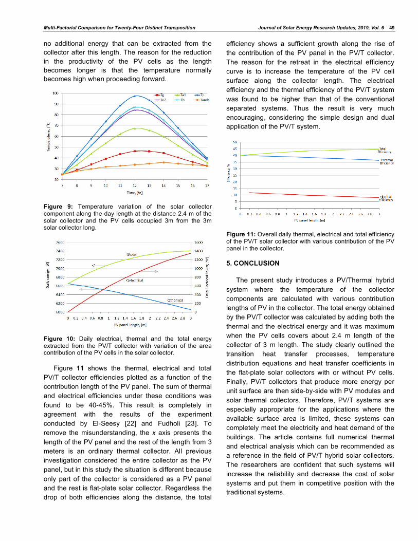
no additional energy that can be extracted from the collector after this length. The reason for the reduction in the productivity of the PV cells as the length becomes longer is that the temperature normally becomes high when proceeding forward.
Figure 9: Temperature variation of the solar collector component along the day length at the distance 2.4 m of the solar collector and the PV cells occupied 3m from the 3m solar collector long.
Figure 10: Daily electrical, thermal and the total energy extracted from the PV/T collector with variation of the area contribution of the PV cells in the solar collector.
Figure 11 shows the thermal, electrical and total PV/T collector efficiencies plotted as a function of the contribution length of the PV panel. The sum of thermal and electrical efficiencies under these conditions was found to be 40-45%. This result is completely in agreement with the results of the experiment conducted by El-Seesy [22] and Fudholi [23]. To remove the misunderstanding, the x axis presents the length of the PV panel and the rest of the length from 3 meters is an ordinary thermal collector. All previous investigation considered the entire collector as the PV panel, but in this study the situation is different because only part of the collector is considered as a PV panel and the rest is flat-plate solar collector. Regardless the drop of both efficiencies along the distance, the total
efficiency shows a sufficient growth along the rise of the contribution of the PV panel in the PV/T collector. The reason for the retreat in the electrical efficiency curve is to increase the temperature of the PV cell surface along the collector length. The electrical efficiency and the thermal efficiency of the PV/T system was found to be higher than that of the conventional separated systems. Thus the result is very much encouraging, considering the simple design and dual application of the PV/T system.
Figure 11: Overall daily thermal, electrical and total efficiency of the PV/T solar collector with various contribution of the PV panel in the collector.
5. CONCLUSION
The present study introduces a PV/Thermal hybrid system where the temperature of the collector components are calculated with various contribution lengths of PV in the collector. The total energy obtained by the PV/T collector was calculated by adding both the thermal and the electrical energy and it was maximum when the PV cells covers about 2.4 m length of the collector of 3 m length. The study clearly outlined the transition heat transfer processes, temperature distribution equations and heat transfer coefficients in the flat-plate solar collectors with or without PV cells. Finally, PV/T collectors that produce more energy per unit surface are then side-by-side with PV modules and solar thermal collectors. Therefore, PV/T systems are especially appropriate for the applications where the available surface area is limited, these systems can completely meet the electricity and heat demand of the buildings. The article contains full numerical thermal and electrical analysis which can be recommended as a reference in the field of PV/T hybrid solar collectors. The researchers are confident that such systems will increase the reliability and decrease the cost of solar systems and put them in competitive position with the traditional systems.

50 Journal of Solar Energy Research Updates, 2019, Vol. 6 Nassar et al.
REFERENCES
[1] Nassar YF, Salem AA. The reliability of the photovoltaic utilization in southern cities of Libya, Desalination 209 (2007); 86-90. https://doi.org/10.1016/j.desal.2007.04.013
[2] Salem AA, Nassar YF, Yousif SA. The Choice of Solar Energy in the Field of Electrical Generation -Photovoltaic or Solar Thermal - For Arabic Region, World Renewable Energy Congress VIII (WREC 2004). Copyright 2004. Published by Elsevier Ltd.
[3] Chow TT. A review on photovoltaic/thermal hybrid solar technology, Applied Energy 2010; 87(2): 365-379. https://doi.org/10.1016/j.apenergy.2009.06.037
[4] Al-Waeli AHA, Sopian K, Kazem HA, Chaichan MT. Photovoltaic/Thermal (PV/T) systems: Status and future prospects, Renewable and Sustainable Energy Reviews 2017; 77: 109-130. https://doi.org/10.1016/j.rser.2017.03.126
[5] Hamid SA, Othman MY, Sopian K and Zaidi SH. An over view of photovoltaic thermal combination (PV/T) technology, Science Direct, Renewable and Sustainable Energy Reviews 2014; 38: 212-222. https://doi.org/10.1016/j.rser.2014.05.083
[6] Hegazy AA. Comparative study of the performances of four photovoltaic/thermal solar air collectors, Energy Conservation & Managemant 2000; 41: 861-881. https://doi.org/10.1016/S0196-8904(99)00136-3
[7] Singh BSS, Yen CH, Zaidi SH, Sopian K. Enhanced performance of concentrating photovoltaic- thermal air collector with fresnel lens and compound parabolic concentrator, Journal of Advanced Research in Fluid Mechanics and Thermal Sciences 2018: 16-24.
[8] Mohd YHj, Othman FH, Kamaruzzman S, Baharuddin Y, and Hafidz R. Design of various hybrid single-pass photovoltaic-thermal (PV/T) solar collector, Renewable energy in the service of mankind, Springer international publishing Switzerland 2016; 2(56): 625-634. https://doi.org/10.1007/978-3-319-18215-5_56
[9] Niccolò A, Fabrizio L and Claudio P. Design, modelling and performance monitoring of a photovoltaic-thermal (PVT) water collector, Solar Energy 2015; 112: 85-99. https://doi.org/10.1016/j.solener.2014.11.025
[10] Hasila J, Mohd NA, Norain AM, Mahmod O and Mahadzir H. Investigation on the thermal characteristics of a Bi-fluid-type hybrid photovoltaic/thermal (PV/T) solar collector, Renewable energy in the service of mankind, Springer international publishing Switzerland, 2016; 2(87): 973-982.
https://doi.org/10.1007/978-3-319-18215-5_87 [11] Theoretical and experimental study of new configuration of
PVT collector, Journal of Solar Energy Engineering 2017; 139(2): 1-7 https://doi.org/10.1115/1.4035328
[12] Michael JJ and Selvarasan I. Experimental investigation of a copper sheet - laminated solar photovoltaic thermal water collector, Energy Efficiency 2016; 1-12. https://doi.org/10.1007/s12053-016-9443-x
[13] Nassar YF, and Sharif MA. Economic and energetic analysis for optimizing the length of flat-plate solar air heating collectors. Specialized Collections, Solar Energy: Engineering of Solar Energy Systems 2015; 2378-2385.
[14] Elbreki AM, Alghoul MA, Al-Shamani AN, Ammara AA, Bita Y, Alsanossi MA et al. The role of climatic-design-operational parameters on combined PV/T collector performance: A critical review, Science Direct, Renewable and Sustainable Energy Reviews 2016; 57: 602-647. https://doi.org/10.1016/j.rser.2015.11.077
[15] Nassar YF and Sergievsky ED. Heat transfer in flat-plate solar air-heating collectors, WIT Press, the 6th international conference on advanced computational methods in heat transfer, Madrid, Spain, 26-28 June 2000; 575-584.
[16] Incropera FP, David PD, Theodore LB and Adrienne SL. Fundamentals of Heat and Mass Transfer, John Wiley & Sons, Inc, 6th edition, USA, 2007.
[17] Allan J. The development and characterisation of enhanced hybrid solar photovoltaic thermal systems, PhD thesis, (May 2015), Brunel University, UK.
[18] Khamooshi M, Salati H, Egelioglu F, Hooshyar F, Tarabishi J and Babadi S. A review of solar photovoltaic concentrators, International Journal of Photoenergy 2014; 214: 1-17. https://doi.org/10.1155/2014/958521
[19] http://www.solarprofessional.com [20] Nassar YF. Thermodynamics analysis and optimization
procedure for domestic solar water heating system, AASCIT, American Journal of Energy and Power Engineering 2015; 2(6): 92-99. [online] available: www.aascit.org/ journal/ajepe.
[21] Nassar YF. Solar energy engineering active applications, Sebha University, Libya 2006. "Arabic language"
[22] El-Seesy IE, Khalil T and Ahmed MH. Experimental investigations and developing of photovoltaic-thermal system, World Applied Sciences Journal 2012; 19(9): 1342-1347.
[23] Fudholi AR & D in photovoltaic thermal (PVT) systems, Peer review journal of solar & photoenergy systems 2018; 1-2.
Received on 5-6-2019 Accepted on 24-6-2019 Published on 12-7-2019 DOI: http://dx.doi.org/10.15377/2410-2199.2019.06.5
© 2019 Nassar et al.; Zeal Press. This is an open access article licensed under the terms of the Creative Commons Attribution Non-Commercial License (http://creativecommons.org/licenses/by-nc/3.0/), which permits unrestricted, non-commercial use, distribution and reproduction in any medium, provided the work is properly cited.


