Embed Size (px)
Citation preview

lable at ScienceDirect
Journal of Nuclear Materials 466 (2015) 179e186
Contents lists avai
Journal of Nuclear Materials
journal homepage: www.elsevier .com/locate/ jnucmat
Microstructural evolution in NF616 (P92) and Fee9Cre0.1C-modelalloy under heavy ion irradiation
Cem Topbasi a, *, Djamel Kaoumi b, Arthur T. Motta a, c, Mark A. Kirk d
a Department of Materials Science and Engineering, Pennsylvania State University, University Park, 16802 PA, USAb Department of Mechanical and Nuclear Engineering, University of South Carolina, 300 Main St., Columbia, SC 29208, USAc Department of Mechanical and Nuclear Engineering, Pennsylvania State University, University Park, 16802 PA, USAd Materials Science Division, Argonne National Laboratory, Argonne, IL 60439, USA
a r t i c l e i n f o
Article history:Received 26 October 2014Received in revised form22 June 2015Accepted 2 July 2015Available online 7 July 2015
Keywords:Generation-IV nuclear reactorsSodium-cooled fast reactorHeavy ion irradiationIn situ techniqueTransmission electron microscopyFerritic-martensitic alloysModel alloys
* Corresponding author.E-mail address: [email protected] (C. Topbasi).
http://dx.doi.org/10.1016/j.jnucmat.2015.07.0030022-3115/© 2015 Elsevier B.V. All rights reserved.
a b s t r a c t
In this comparative study, in situ investigations of the microstructure evolution in a Fee9Cr ferriticemartensitic steel, NF616, and a Fee9Cre0.1C-model alloy with a similar ferriticemartensitic micro-structure have been performed. NF616 and Fee9Cre0.1C-model alloy were irradiated to high doses (upto ~10 dpa) with 1 MeV Kr ions between 50 and 673 K. Defect cluster density increased with dose andsaturated in both alloys. The average size of defect clusters in NF616 was constant between 50 and 573 K,on the other hand average defect size increased with dose in Fee9Cre0.1C-model alloy around ~1 dpa. Atlow temperatures (50e298 K), alignment of small defect clusters resulted in the formation of extensivedefects in Fee9Cre0.1C-model alloy around ~2e3 dpa, while similar large defects in NF616 started toform at a high temperature of 673 K around ~5 dpa. Interaction of defect clusters with the lathboundaries were found to be much more noticeable in Fee9Cre0.1C-model alloy. Differences in themicrostructural evolution of NF616 and Fee9Cre0.1C-model alloy are explained by means of the defectcluster trapping by solute atoms which depends on the solute atom concentrations in the alloys.
© 2015 Elsevier B.V. All rights reserved.
1. Introduction
High chromium (9e12 wt.%) ferritic-martensitic (FeM) steelsare amongst the candidate in-core structural materials for futurefusion energy systems and one of the Generation IV (GEN-IV)fission energy systems, the Sodium Fast Reactor (SFR) [1]. FeMsteels are considered for fuel cladding and internal applications inSFR, as well as first wall and blanket materials in future fusionconcepts due to their high resistance to irradiation induced voidswelling, good microstructural stability and good thermal proper-ties [2]. For these applications the FeM steels are envisioned tooperate at high temperatures (573e873 K) and have to withstandhigh levels of radiation damage (150e200 dpa) [1].
Normalized and tempered 9e12 wt.% FeM steels typicallyexhibit the tempered martensite structure characterized by finelaths and sub-grains with a high dislocation density [2]. Majorimprovements in the high temperature creep resistance of9e12 wt.% Cr FeM steels were established through alloying in the
last century [2]. The modifications in the composition of the FeMsteels include fine adjustments in solid solution and precipitationstrengthening elements, the combination of which resulted insignificant improvements in material properties outside irradiation[2].
The high-energy neutrons produced during fusion and fissioncause displacement damage. A distribution of interstitial and va-cancy defect clusters of various sizes forms as a result of high en-ergy displacement cascades [3,4]. The fate of these defects plays adetermining role in radiation effects such as hardening, embrit-tlement, growth, creep and swelling. The mechanisms of radiationdamage and irradiation-induced microstructural evolution havebeen extensively studied in pure Fe and binary FeeCr alloys [4e7].Jenkins et al. reported results of both in situ and ex situ irradiationsof pure Fe and Fe-(5e18)Cr alloys with 100e150 keV Fe and Xe ionsat 298 K, 573 K and 773 K [6e8]. Ultra-high purity Fe and binaryFeeCr alloys exhibited a ferritic structure with large grains and alow density of pre-existing dislocations and precipitates. At earlydoses, the irradiation damage in these systems appeared as small(2e4 nm) defect clusters (assumed to be loops) [7] while at higherdoses strings of defect clusters and resolvable loops were observed[8]. Defect analysis showed that a mixed population of dislocation
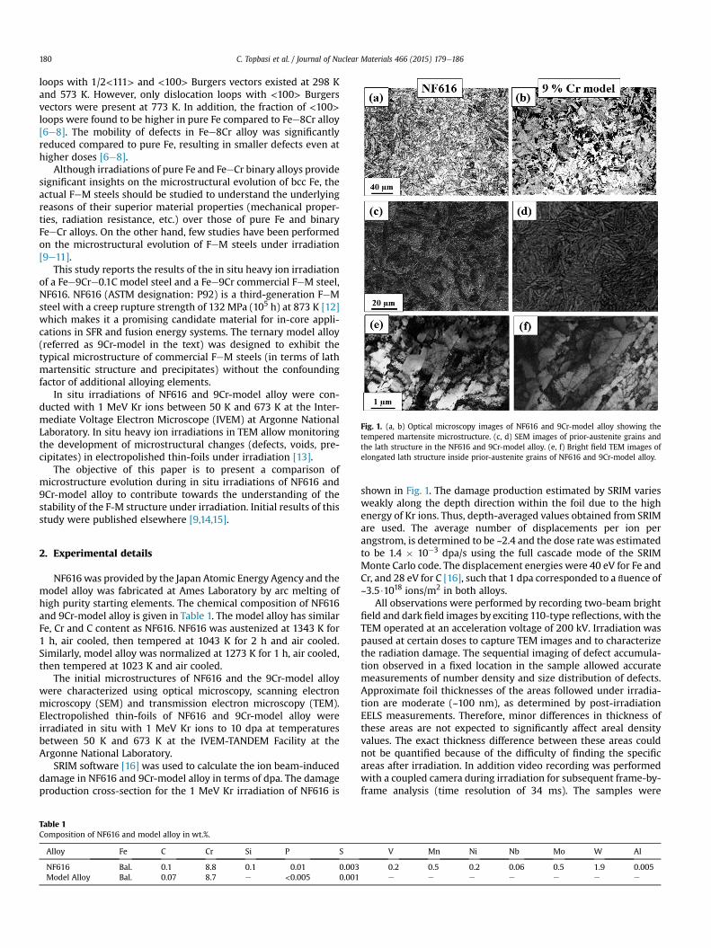
Fig. 1. (a, b) Optical microscopy images of NF616 and 9Cr-model alloy showing thetempered martensite microstructure. (c, d) SEM images of prior-austenite grains andthe lath structure in the NF616 and 9Cr-model alloy. (e, f) Bright field TEM images ofelongated lath structure inside prior-austenite grains of NF616 and 9Cr-model alloy.
C. Topbasi et al. / Journal of Nuclear Materials 466 (2015) 179e186180
loops with 1/2<111> and <100> Burgers vectors existed at 298 Kand 573 K. However, only dislocation loops with <100> Burgersvectors were present at 773 K. In addition, the fraction of <100>loops were found to be higher in pure Fe compared to Fee8Cr alloy[6e8]. The mobility of defects in Fee8Cr alloy was significantlyreduced compared to pure Fe, resulting in smaller defects even athigher doses [6e8].
Although irradiations of pure Fe and FeeCr binary alloys providesignificant insights on the microstructural evolution of bcc Fe, theactual FeM steels should be studied to understand the underlyingreasons of their superior material properties (mechanical proper-ties, radiation resistance, etc.) over those of pure Fe and binaryFeeCr alloys. On the other hand, few studies have been performedon the microstructural evolution of FeM steels under irradiation[9e11].
This study reports the results of the in situ heavy ion irradiationof a Fee9Cre0.1C model steel and a Fee9Cr commercial FeM steel,NF616. NF616 (ASTM designation: P92) is a third-generation FeMsteel with a creep rupture strength of 132 MPa (105 h) at 873 K [12]which makes it a promising candidate material for in-core appli-cations in SFR and fusion energy systems. The ternary model alloy(referred as 9Cr-model in the text) was designed to exhibit thetypical microstructure of commercial FeM steels (in terms of lathmartensitic structure and precipitates) without the confoundingfactor of additional alloying elements.
In situ irradiations of NF616 and 9Cr-model alloy were con-ducted with 1 MeV Kr ions between 50 K and 673 K at the Inter-mediate Voltage Electron Microscope (IVEM) at Argonne NationalLaboratory. In situ heavy ion irradiations in TEM allow monitoringthe development of microstructural changes (defects, voids, pre-cipitates) in electropolished thin-foils under irradiation [13].
The objective of this paper is to present a comparison ofmicrostructure evolution during in situ irradiations of NF616 and9Cr-model alloy to contribute towards the understanding of thestability of the F-M structure under irradiation. Initial results of thisstudy were published elsewhere [9,14,15].
2. Experimental details
NF616was provided by the Japan Atomic Energy Agency and themodel alloy was fabricated at Ames Laboratory by arc melting ofhigh purity starting elements. The chemical composition of NF616and 9Cr-model alloy is given in Table 1. The model alloy has similarFe, Cr and C content as NF616. NF616 was austenized at 1343 K for1 h, air cooled, then tempered at 1043 K for 2 h and air cooled.Similarly, model alloy was normalized at 1273 K for 1 h, air cooled,then tempered at 1023 K and air cooled.
The initial microstructures of NF616 and the 9Cr-model alloywere characterized using optical microscopy, scanning electronmicroscopy (SEM) and transmission electron microscopy (TEM).Electropolished thin-foils of NF616 and 9Cr-model alloy wereirradiated in situ with 1 MeV Kr ions to 10 dpa at temperaturesbetween 50 K and 673 K at the IVEM-TANDEM Facility at theArgonne National Laboratory.
SRIM software [16] was used to calculate the ion beam-induceddamage in NF616 and 9Cr-model alloy in terms of dpa. The damageproduction cross-section for the 1 MeV Kr irradiation of NF616 is
Table 1Composition of NF616 and model alloy in wt.%.
Alloy Fe C Cr Si P S
NF616 Bal. 0.1 8.8 0.1 0.01 0.003Model Alloy Bal. 0.07 8.7 e <0.005 0.001
shown in Fig. 1. The damage production estimated by SRIM variesweakly along the depth direction within the foil due to the highenergy of Kr ions. Thus, depth-averaged values obtained from SRIMare used. The average number of displacements per ion perangstrom, is determined to be ~2.4 and the dose rate was estimatedto be 1.4 � 10�3 dpa/s using the full cascade mode of the SRIMMonte Carlo code. The displacement energies were 40 eV for Fe andCr, and 28 eV for C [16], such that 1 dpa corresponded to a fluence of~3.5$1018 ions/m2 in both alloys.
All observations were performed by recording two-beam brightfield and dark field images by exciting 110-type reflections, with theTEM operated at an acceleration voltage of 200 kV. Irradiation waspaused at certain doses to capture TEM images and to characterizethe radiation damage. The sequential imaging of defect accumula-tion observed in a fixed location in the sample allowed accuratemeasurements of number density and size distribution of defects.Approximate foil thicknesses of the areas followed under irradia-tion are moderate (~100 nm), as determined by post-irradiationEELS measurements. Therefore, minor differences in thickness ofthese areas are not expected to significantly affect areal densityvalues. The exact thickness difference between these areas couldnot be quantified because of the difficulty of finding the specificareas after irradiation. In addition video recording was performedwith a coupled camera during irradiation for subsequent frame-by-frame analysis (time resolution of 34 ms). The samples were
V Mn Ni Nb Mo W Al
0.2 0.5 0.2 0.06 0.5 1.9 0.005e e e e e e e
C. Topbasi et al. / Journal of Nuclear Materials 466 (2015) 179e186 181
electropolished by using a 5% HClO4 and 95% CH3OH solutioncooled down to 233 K by liquid nitrogen. Details of the samplepreparation and of the in situ heavy-ion irradiation experimentwere published elsewhere [9,14,15].
3. Results
3.1. Microstructure of NF616 and 9Cr-model alloy
The as-received microstructures of NF616 and 9Cr-model alloyare shown in Fig.1. Fig.1(a) and (b) show optical microscopy imagesof themicrostructure observed in the twomaterials. Because NF616and 9Cr-model are positioned within the fully martensitic domainof the SchaefflereSchneider Diagram [17]. Fig. 1(c) and (d) displaysecondary electron SEM images of the lath structures inside thelarge prior austenite grains in the two materials. A high density ofM23C6 and M(C,N) precipitates (where M denotes a metallicelement) are present along lath boundaries and prior austeniteboundaries in NF616 [18]. The density of precipitates is lower in the9Cr-model alloy due to the lower concentration of carbide stabi-lizers in this alloy. Fig. 1(e) and (f) show TEM images of both ma-terials showing similar elongated lath structure observed in NF616and 9Cr-model alloy. In NF616 a high density of pre-existing dis-locations formed during the martensitic transformation in theNF616 that are inhomogeneously distributed within the laths isobserved. NF616 exhibits the tempered martensite structure typi-cally observed in 9e12 Cr F-M steels. As shown in Fig. 1, themicrostructure of the 9Cr-model alloy replicates the F-M structure(lath/subgrain and prior-austenite grain boundaries) of NF616reasonably well.
3.2. Irradiation induced microstructure evolution
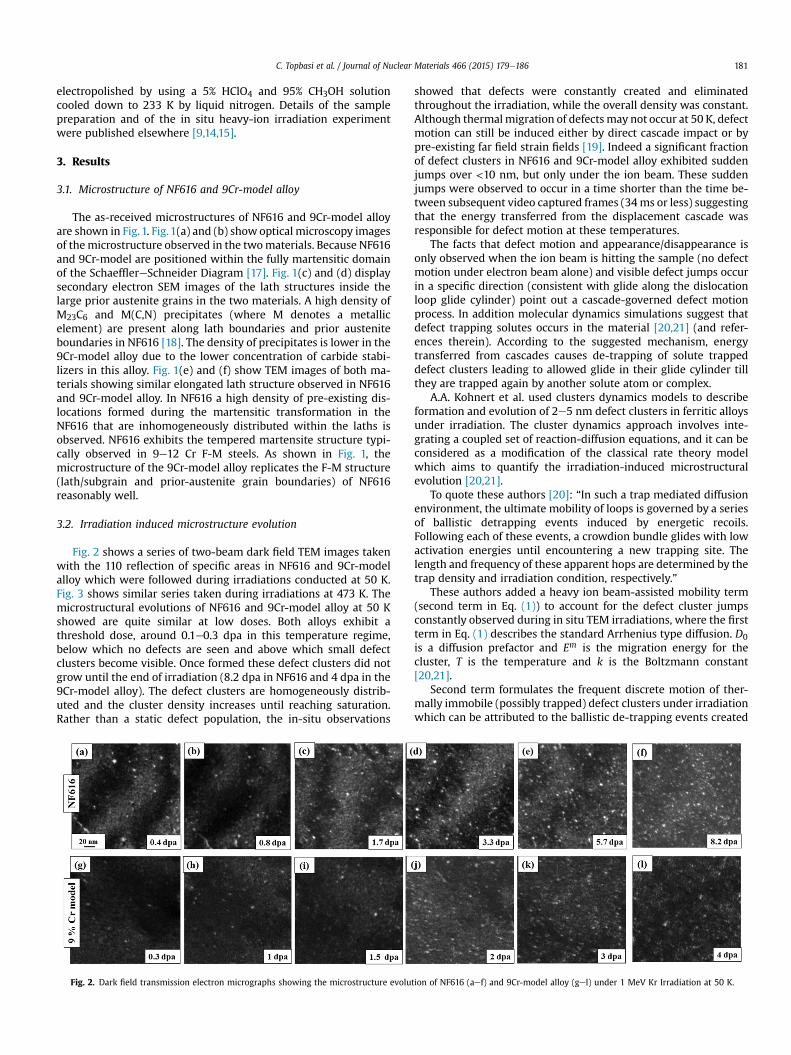
Fig. 2 shows a series of two-beam dark field TEM images takenwith the 110 reflection of specific areas in NF616 and 9Cr-modelalloy which were followed during irradiations conducted at 50 K.Fig. 3 shows similar series taken during irradiations at 473 K. Themicrostructural evolutions of NF616 and 9Cr-model alloy at 50 Kshowed are quite similar at low doses. Both alloys exhibit athreshold dose, around 0.1e0.3 dpa in this temperature regime,below which no defects are seen and above which small defectclusters become visible. Once formed these defect clusters did notgrow until the end of irradiation (8.2 dpa in NF616 and 4 dpa in the9Cr-model alloy). The defect clusters are homogeneously distrib-uted and the cluster density increases until reaching saturation.Rather than a static defect population, the in-situ observations
Fig. 2. Dark field transmission electron micrographs showing the microstructure evolu
showed that defects were constantly created and eliminatedthroughout the irradiation, while the overall density was constant.Although thermalmigration of defects may not occur at 50 K, defectmotion can still be induced either by direct cascade impact or bypre-existing far field strain fields [19]. Indeed a significant fractionof defect clusters in NF616 and 9Cr-model alloy exhibited suddenjumps over <10 nm, but only under the ion beam. These suddenjumps were observed to occur in a time shorter than the time be-tween subsequent video captured frames (34ms or less) suggestingthat the energy transferred from the displacement cascade wasresponsible for defect motion at these temperatures.
The facts that defect motion and appearance/disappearance isonly observed when the ion beam is hitting the sample (no defectmotion under electron beam alone) and visible defect jumps occurin a specific direction (consistent with glide along the dislocationloop glide cylinder) point out a cascade-governed defect motionprocess. In addition molecular dynamics simulations suggest thatdefect trapping solutes occurs in the material [20,21] (and refer-ences therein). According to the suggested mechanism, energytransferred from cascades causes de-trapping of solute trappeddefect clusters leading to allowed glide in their glide cylinder tillthey are trapped again by another solute atom or complex.
A.A. Kohnert et al. used clusters dynamics models to describeformation and evolution of 2e5 nm defect clusters in ferritic alloysunder irradiation. The cluster dynamics approach involves inte-grating a coupled set of reaction-diffusion equations, and it can beconsidered as a modification of the classical rate theory modelwhich aims to quantify the irradiation-induced microstructuralevolution [20,21].
To quote these authors [20]: “In such a trap mediated diffusionenvironment, the ultimate mobility of loops is governed by a seriesof ballistic detrapping events induced by energetic recoils.Following each of these events, a crowdion bundle glides with lowactivation energies until encountering a new trapping site. Thelength and frequency of these apparent hops are determined by thetrap density and irradiation condition, respectively.”
These authors added a heavy ion beam-assisted mobility term(second term in Eq. (1)) to account for the defect cluster jumpsconstantly observed during in situ TEM irradiations, where the firstterm in Eq. (1) describes the standard Arrhenius type diffusion. D0is a diffusion prefactor and Em is the migration energy for thecluster, T is the temperature and k is the Boltzmann constant[20,21].
Second term formulates the frequent discrete motion of ther-mally immobile (possibly trapped) defect clusters under irradiationwhich can be attributed to the ballistic de-trapping events created
tion of NF616 (aef) and 9Cr-model alloy (gel) under 1 MeV Kr Irradiation at 50 K.
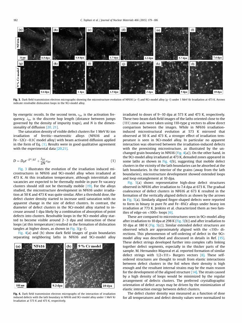
Fig. 3. Dark field transmission electron micrographs showing the microstructure evolution of NF616 (aef) and 9Cr-model alloy (gel) under 1 MeV Kr Irradiation at 473 K. Arrowsindicate resolvable dislocation loops in the 9Cr-model alloy.
C. Topbasi et al. / Journal of Nuclear Materials 466 (2015) 179e186182
by energetic recoils. In the second term, yirr is the activation fre-quency, lirr is the discrete hop length (distance between jumpsgoverned by the density of impurity traps), and N is the dimen-sionality of diffusion [20, 21].
The saturation density of visible defect clusters for 1 MeV Kr ionirradiation of ferriticemartensitic alloys (NF616 and aFee12Cre0.1C model alloy) with beam activated diffusion appliedin the form of Eq. (1). Results were in good qualitative agreementwith the experimental data [20,21].
D ¼ D0e�Em=kT þ lirr
2Nyirr (1)
Fig. 3 illustrates the evolution of the irradiation induced mi-crostructures in NF616 and 9Cr-model alloy when irradiated at473 K. At this irradiation temperature, although interstitials andvacancies are expected to be thermally mobile in pure Fe vacancyclusters should still not be thermally mobile [19]. For the alloysstudied, the microstructure development in NF616 under irradia-tion at 50 K and 473 K was quite similar. After a threshold dose, thedefect cluster density started to increase until saturation with noapparent change in the size of defect clusters. In contrast, thediameter of defect clusters in the 9Cr-model alloy started to in-crease around 1 dpa likely by a combination of absorption of pointdefects into clusters. Resolvable loops in the 9Cr-model alloy star-ted to become visible around 2e3 dpa and interaction of theseloops (at this temperature) resulted in the formation of dislocationtangles at higher doses, as shown in Fig. 3(gel).
Fig. 4(a) and (b) show dark field images of grain boundariesseparating neighboring laths in NF616 and 9Cr-model alloy
Fig. 4. Dark field transmission electron micrographs of the interaction of irradiationinduced defects with the lath boundary in NF616 and 9Cr-model alloy under 1 MeV KrIrradiation at 573 K and 473 K, respectively.
irradiated to doses of 9e10 dpa at 573 K and 473 K, respectively.These two-beam dark field images of the laths oriented close to the(111) zone axis were taken using 110-type g vectors to allow directcomparison between the images. While in NF616 irradiation-induced microstructural evolution at 573 K mirrored thatobserved at 50 K and 473 K, a stronger effect of irradiation tem-perature is seen in 9Cr-model alloy. In particular no apparentinteraction was observed between the irradiation-induced defectswith the preexisting microstructure, as illustrated by the un-changed grain boundary in NF616 (Fig. 4(a)). On the other hand, inthe 9Cr-model alloy irradiated at 473 K, denuded zones appeared insome laths as shown in Fig. 4(b), suggesting that mobile defectclusters in the vicinity of the lath boundaries can be absorbed at thelath boundaries. In the interior of the grains (away from the lathboundaries), microstructure development showed extended loopsand loop entanglement at 10 dpa.
Fig. 5(a) shows representative high-dose defect structuresobserved in NF616 after irradiation to 7.4 dpa at 673 K. The gradualcoalescence of defect clusters in NF616 at 673 K resulted in theformation of the vertically aligned defects as shown by the arrowsin Fig. 5(a). Similarly aligned finger-shaped defects were reportedto form in binary in pure Fe and Fee8%Cr alloys under heavy ionirradiation at 773 K. Jenkins et al. characterized them as two fam-ilies of edge-on <100> loops [6].
These are compared to microstructures seen in 9Cr-model alloyafter irradiation to 10 dpa at 298 K (Fig. 5(b)) and after irradiation to10 dpa at 180 K (Fig. 5(c)). Similar extended defect structures areobserved which are approximately aligned with the <110> di-rections. This phenomenon of self-ordering of defect in the 9Cr-model alloy was described and discussed in details in Ref. [15].These defect strings developed further into complex rafts linkingtogether defect segments, especially in the thicker parts of thesample. M. Hernandez-Mayoral et al. reported formation of similardefect strings with 1/2<111> Burgers vectors [8]. These self-ordered structures are thought to result from elastic interactionsbetween defect clusters in the foil when their density is highenough and the resultant internal strains may be the main reasonfor the development of the aligned structure [14]. The strain causedby a high density of loops would be minimized by the regulararrangement of defects clusters. The preferred crystallographicorientation of defect arrays may be driven by the minimization ofelastic interaction energy between defect clusters.
The defect cluster density was measured as a function of dosefor all temperatures and defect density values were normalized to

Fig. 5. Bright field transmission electron micrographs of extended defects observed in NF616 and 9Cr-model alloy under 1 MeV Kr irradiations performed at 673 K (a), 298 K (b) and180 K (c), respectively. Arrows indicate approximate directions of defect alignment in NF616 and 9Cr-model alloy.
C. Topbasi et al. / Journal of Nuclear Materials 466 (2015) 179e186 183
the highest value acquired for each alloy, plus the error bar. Fig. 6shows the normalized defect cluster density with increasing dosefor NF616 during irradiation at 50 K, 473 K and 673 K to 8 dpa andof the defect cluster density ion the 9Cr-model alloy when irra-diated at 50 K and 473 K to 2 dpa. The measured defect clusterdensity in NF616 at ~6 dpa, while that for the 9Cr-model alloysaturates earlier in dose. The defect cluster density in both alloysdecreased with increasing temperature. Between 50 K (highestdensity) and 473 K the decrease in saturation density of NF616was ~10% while for the 9Cr-model alloys showed a decrease of~70%, in its saturation defect cluster density. In NF616 the irradi-ation at 673 K shows a large decrease in defect cluster density,suggesting the onset of a thermally driven regime at that tem-perature. This onset of thermally driven regime was seen alreadyat 473 K for the 9Cr0-model alloy.
Fig. 7(a) shows the average defect cluster size in NF616 at 50 K,473 K and 673 K. It is clear that the defect size does not change witheither dose or temperature, except at 673 K. For the 9Cr-model alloythe defect size is approximately constant at these low doses forirradiations at 50 K and 473 K. The average defect size in NF616 wasaround 3e4 nm at 50 K and 473 K, while it almost doubled at 673 K.On the other hand, the average defect size was 35e38% larger in thematerial irradiated at 473 K than that measured at 50 K in the 9Cr-model alloy.
There was no evidence of void formation or precipitation ineither alloy at the irradiation doses and temperatures studied.
Fig. 6. Normalized defect cluster areal density of (a) NF616 and (b) 9Cr-model alloy as a funhighest value acquired at 50 K (~0.005 defects.nm�2 at 5.5 dpa for NF616 and ~0.006 defec
4. Discussion
The common characteristics and dissimilarities between theirradiation induced microstructural evolution in NF616 and in 9Cr-model alloy are as follows:
(i) Defect formation and visibility: The initial visible damage(2e4 nm sized white dots in DF TEM images) under the1 MeV Kr irradiations appeared at cascade overlap doses.This indicates formation of defect clusters in cascade eventsby the impact of cascades on a volume which contains abackground density of defects created by prior ion collisionsthat are not visible in TEM (i.e. under TEM resolution). This isin agreement with previous studies of the onset of defectaccumulation in bcc Fe under ion irradiation. The collapse ofindividual, isolated cascades to visible defects in Fe did notoccur under heavy-ion irradiations however visible damagewas observed at relatively high irradiation doses [7,11,22]. Atcryogenic temperatures (50 K) irradiation-induced defectclusters do not become visible until higher doses. This sug-gests that TEM-invisible defects become visible/detectableonly when they have grown to a size larger than the TEMresolution limit, by cascade induced defect cluster motion ordirect overlap. It was not possible to determine the nature ofthe nanometer sized defects observed in our in situ irradia-tions since size of the defect clusters is too small to apply
ction of dose at 50 K, 473 K and 673 K. The defect cluster density is normalized to thets.nm�2 at 2 dpa for 9Cr-model alloy) was calculated, plus the error bar.

Fig. 7. Average defect cluster size of (a) NF616 and (b) 9Cr-model alloy as a function of dose at 50 K, 473 K and 673 K.
C. Topbasi et al. / Journal of Nuclear Materials 466 (2015) 179e186184
inside-outside contrast method. Nevertheless, previousstudies about the irradiation-induced defects in Fe showedthat defects that were large enough to characterize werehighly mobile interstitials. On the other hand, relativelyimmobile vacancy clusters remain themicrostructure as sub-visible (<2 nm) defect clusters that are not observable byTEM. The interstitial clusters are likely created directly incascades and trapped by impurities in the material.
(ii) Defect motion/jumps: The defect clusters constantlyappeared anddisappearedunder the ion beam. Flickering andsudden jumps of white dots in DF TEM imageswere observedearly on during the irradiations and continued above thesaturation dose resulting in a dynamic picture under irradi-ation. The one-dimensional jumps of clusters were observedin both alloys. However, “to-and-fro hops” of clusters (i.e.sudden back and forth (1D) movements about the same po-sition) often observed in ultra-high purity iron systems [8]were more rarely seen in these more complex alloys and thedefect jumps had a smaller rattling frequency; the jump dis-tances in the current alloyswere less than the jumpsobservedby others in pure iron [8]. When such cluster hops occurredduring irradiation, the cluster could spend a few secondsbefore jumping back to the previous position, suggesting thatimpurity trapping slows down themotion of these clusters. Inaddition mobile interstitial clusters may interact with otherinterstitial and vacancy clusters during their glide betweentraps (solute atoms and complexes). These interactions canchange the size of the interstitial clusters (increase in the caseof interstitial and decrease in the case of a vacancy). The effectof these coalescence events on the mobility of interstitialclusters is unknown and requires further investigation.
(iii) Defect density dependence on dose: The areal density ofthe TEM-visible defect clusters increased with dose,approaching an apparent dynamic saturation, in which de-fects are constantly created and destroyed at the same rate. Itis expected that, with increasing irradiation dose, the va-cancy cluster concentration will steadily increase such thatinterstitial clusters will increasingly gather vacancies as theyglide between solute traps. This will cause saturation indefect density and limit the interstitial cluster size. In thisscenario, a steady state could be established inwhich a stableconcentration of interstitial clusters of fixed size is formedwhich will coexist with a high density of vacancies whichwill preclude further growth.
(iv) Defect size: The constant defect size in NF616 between 50 Kand 573 K indicates a significant reduction in the mobility ofdefects in this wide temperature range, likely caused byimpurity trapping. On the other hand, larger defects form inthe 9Cr-model alloy at 473 K. In addition the decrease in thedensity of defects between 50 K and 473 K was more pro-nounced in the 9Cr-model alloy compared to NF616. This canbe attributed to the higher mobility of defects in the modelalloy which can result in a higher rate of recombination anddefect loss to the sinks. In accordance, defect-denuded zonesalong the grain boundaries were observed only in the 9Cr-model alloy, indicating enhanced transport of defects to sinksin the model alloy relative to NF616 whose chemicalcomposition indicates higher solute content.
The exact mechanisms of loop growth are expected to affect thedose dependence of the average loop size (as well as the loopdensity), i.e. whether loop growth happens by (i) diffusion andabsorption of single point defects, (ii) by diffusion and absorption ofsmaller clusters (iii) by cascade overlap, or (iv) by loop coalescence.In contrast with what is seen in pure Fe, loop coalescence was notobserved in either alloy likely because of impurity trapping; how-ever small black dots were seen decorating larger loops in 9Cr-model alloy suggesting that the larger loops can grow by absorptionof smaller clusters and point defects. These can be small clustersformed in the direct vicinity of the loops, either swept there bycascade impact at the lowest temperatures or by thermal migrationat the highest temperatures above stage II.
The differences in the microstructural evolution of NF616 and9Cr-model alloy including the formation of denuded zones, theeffect of temperature on average defect size and defect densitycould be explained within the framework of the trapping ofdefects by solute atoms due to the difference in solute concen-tration between the two alloys. Molecular dynamics simulations[3,23,24] showed that interstitial and substitutional point defectsand their clusters can form directly in cascades and interstitialdefect clusters (<100 member) diffuse with activation energiescomparable to one of single self-interstitials in the absence ofsolute atoms by exhibiting a collective motion of interstitialcrowdions [25]. The distribution of solute atoms in NF616 and9Cr-model alloy and the magnitude of the binding energy be-tween solute atoms an defects may strongly affect their mobilitytherefore controlling processes such as defect coalescence andmigration to sinks.

C. Topbasi et al. / Journal of Nuclear Materials 466 (2015) 179e186 185
The concentration of alloying elements in NF616 is considerablyhigher than in the 9Cr-model alloy. Although a fraction of thesesolute atoms precipitate as carbides and other particles at lath andprior austenite boundaries in NF616 during the tempering treat-ment, a fraction of these alloying elements remain in the matrixand may form Cottrell atmospheres that can pin dislocations andcan reduce the mobility of defect clusters [2,26]. Arakawa et al.reported one-dimensional thermal motion of isolated interstitialdefect clusters (6e20 nm) towards <111> direction in pure Fe, inthe absence of stress [27]. The immobilization of defects below450 K in samples with 0.8 ppm Cwas attributed to the formation ofthe Cottrell atmosphere around the defects by the authors [27]. Therelatively lowdensity of C and N (~0.8 ppm) in Fe necessitated theseslow moving interstitials to diffuse towards the defect clusters (orvice versa) to immobilize them. In addition substitutional soluteatoms can act as barriers to defect motion by creating strain fieldsin the matrix, depending on their misfit factor [28]. In situ electronirradiations conducted by T. Hamaoka et al. showed a significantdecrease in the mobility of defect clusters in Fe upon addition of50 appm oversized Cu and undersized Si [28].
A high density of solute atoms in the matrix of NF616 can trapirradiation induced point defects once they are created. This is inagreement with our observations of no temperature dependence ofmicrostructure evolution in NF616 up to 673 K in contrast with the9Cr-model alloy for which a temperature effect was noticed above180 K. A higher density of matrix solute atoms can also explain theshorter length of ion beam induced sudden jumps in NF616 than in9Cr-model alloy. The ion beam induced sudden jumps in 9Cr-modelalloy were in turn found to be shorter than those seen duringirradiation of pure Fe [8]. That is, as the solute concentration in-creases, the ion beam induced jumps become shorter.
Results indicate a wide non-thermally controlled temperatureregime (50 K < T < 573 K) in NF616 which is characterized byconstant defect size and restricted defect motion. On the otherhand, this “cascade-governed regime” in 9Cr-model alloy seems tobe limited to lower temperatures (T < 298 K). Dislocation loopgrowth and formation of extended defect structures involvingresolvable loops could be observed in the 9Cr-model alloy at 473 Kand 573 K, whereas these were only seen in NF616 at 673 K and to alesser degree. We note however that the gradual coalescence ofdefects into extended defects was only observed under the ionbeam (i.e. not under thermal annealing) which indicates that irra-diation enhanced thermal diffusion or cascade driven diffusion isnecessary at 673 K.
(v) The alignment of defects: Rafts of defects formed alignedalong <110> directions at high doses in 9Cr-model alloybetween 50 K and 573 K (Fig. 5). These extended defects canform as a result of a high density of evenly distributed defectclusters in 9Cr-model alloys which can result in short-rangeelastic interactions between defect clusters in close vicinityto each other causing them to align and thus minimize strainenergy. Kinetic Monte Carlo simulations conducted by M.Wen et al. suggest that mutual strain fields between inter-stitial clusters can cause them to move in their glide cylinder[29]. There was less indication of defect alignment in NF616likely because of solute pinning.
5. Conclusions
In situ irradiations of NF616 and 9Cr-model alloy were per-formed with 1 MeV Kr ions between 50 K and 673 K to investigatemicrostructure evolution in these alloys using identical samplepreparation and in situ irradiation setup to enable direct
comparison. The main results are as follows:
1. Quantitative analysis indicates that defect cluster density in-creases with dose and saturates in both alloys during irradia-tions conducted between 50 and 673 K.
2. The average size of irradiation-induced defect clusters in NF616does not vary with dose or temperature between 50 and 573 Kwhereas the average defect size increases moderately with dosein 9Cr-model alloy.
3. Extended defect structures resulting from the alignment ofsmall defect clusters were observed at high doses in the 9Cr-model alloy for irradiations conducted between 50 and 298 Kwhereas larger defect structures started to form in NF616 only at673 K. These “self-ordered” defect structures were finer in scaleand less aligned than in the 9Cr-model alloy.
4. Interaction of the irradiation induced defects with the pre-existing lath boundaries was observed in the 9Cr-model alloybut not in NF616.
5. No voids or irradiation-induced precipitates were observed ineither alloy for the irradiation temperatures and doses studied.
6. In general the results were consistent with increased defectcluster trapping by solutes in NF616 than in 9Cr-model alloy,leading to a wider temperature range where thermal effectswere less significant in NF616, which emphasizes the impact ofsolutes on the evolution of irradiation induced microstructureeven when the pre-existing (lath/precipitate) microstructure issimilar.
Acknowledgments
This work was funded by the Nuclear Energy University Pro-grams (NEUP) under Award number DE-FG07-07ID14894 from theU.S. Department of Energy. The research conducted in the IVEM-Accelerator facility at Argonne National Laboratory, which is sup-ported as a User Facility by the U.S. Department of Energy, BasicEnergy Sciences, under contract W-31-109-ENG-38. We thank PeteBaldo and Ed Ryan of Argonne National Lab for his help in per-forming the irradiations. We also thank Brian Wirth and AaronKohnert for helpful discussions.
References
[1] A Technology Roadmap for Generation IV Nuclear Energy Systems, US DOENERAC and Generation IV International Forum, 2002. GIF-002-00.
[2] R.L. Klueh, D.R. Harries, High Chromium Ferritic and Martensitic Steels forNuclear Applications, American Society for Testing and Materials, West Con-shohocken, PA, 2001.
[3] D.J. Bacon, Y.N. Osetsky, R. Stoller, R.E. Voskoboinikov, J. Nucl. Mater. 323(2003) 11.
[4] A.F. Calder, D.J. Bacon, A.V. Barashev, Y.N. Osetsky, Phil. Mag. Lett. 88 (2008)43.
[5] M.R. Gilbert, Z. Yao, M.A. Kirk, M.L. Jenkins, S.L. Dudarev, J. Nucl. Mater. 388(2009) 36.
[6] M.L. Jenkins, Z. Yao, M. Hern�andez-Mayoral, M.A. Kirk, J. Nucl. Mater. 389(2009) 197.
[7] Z. Yao, M. Hern�andez-Mayoral, M.L. Jenkins, M.A. Kirk, Philos. Mag. 88 (2008)2851.
[8] M. Hern�andez-Mayoral, Z. Yao, M.L. Jenkins, M.A. Kirk, Philos. Mag. 88 (2008)2881.
[9] C. Topbasi, A.T. Motta, M.A. Kirk, J. Nucl. Mater. 425 (2012) 48.[10] T.R. Allen, L. Tan, J. Gan, G. Gupta, G.S. Was, E.A. Kenik, S. Shutthanandan,
S. Thevuthasan, J. Nucl. Mater. 351 (2006) 174.[11] H. Fukushima, Y. Shimomura, H. Yoshida, J. Nucl. Mater. 141e143 (1986) 938.[12] D. Coutsouradis, Materials for advanced power engineering part 1, in: Proc.
Int. Conf. Li�ege 1994, Dordrecht, Netherlands, 1994.[13] M.A. Kirk, P.M. Baldo, A.C. Liu, E.A. Ryan, R.C. Birtcher, Z. Yao, S. Xu,
M.L. Jenkins, M. Hernandez-Mayoral, D. Kaoumi, A.T. Motta, Microsc. Res.Tech. 72 (2009) 182.
[14] D. Kaoumi, J. Adamson, J. Nucl. Mater. 448 (2014) 233.[15] D. Kaoumi, J. Adamson, M.A. Kirk, J. Nucl. Mater. 445 (2014) 12.[16] J.F. Ziegler, SRIM-2008, 2008. http://www.srim.org.[17] H. Schneider, Foundry Trade J. 108 (1960) 562.

C. Topbasi et al. / Journal of Nuclear Materials 466 (2015) 179e186186
[18] P.J. Ennis, A. Zielinska-Lipiec, O. Wachter, A. Czyrska-Filemonowicz, ActaMater. 45 (1997) 4901.
[19] P. Ehrhart, P. Jung, H. Schultz, H. Ullmaier, in: H. Ullmaier (Ed.), Atomic Defectsin Metals, Landolt-B€ornstein, New Series, Group III, vol. 25, Springer-Verlag,Berlin, 1991.
[20] A.A. Kohnert, B.D. Wirth, J. Appl. Phys. 117 (2015) 154305.[21] B.D. Wirth, X. Hu, A. Kohnert, D. Xu, J. Mater. Res. 30 (2015) 1440.[22] M.A. Kirk, M. Robertson, J.S. Vetrano, M.L. Jenkins, L.L. Funk, in: F.H. Garner,
N.H. Packan, A.S. Kumar (Eds.), Radiation-induced Changes in Microstructure:13th International Symposium, ASTM STP 955, American Society for Testingand Materials, Philadelphia, PA, 1987, p. 48.
[23] A.F. Calder, D.J. Bacon, A.V. Barashev, Y.N. Osetsky, J. Nucl. Mater. 382 (2008)91.
[24] B.D. Wirth, Science 318 (2007) 923.[25] Y.N. Osetsky, D.J. Bacon, A. Serra, B.N. Singh, S.I. Golubov, Philos. Mag. 83
(2003) 61.[26] A.H. Cottrell, B. Bilby, Proc. Phys. Soc. A 62 (1949) 49.[27] K. Arakawa, K. Ono, M. Isshiki, K. Mimura, M. Uchikoshi, H. Mori, Science 318
(2007) 956.[28] T. Hamaoka, Y. Satoh, H. Matsui, J. Nucl. Mater. 433 (2013) 180.[29] M. Wen, N.M. Ghoniem, B.N. Singh, Phil. Mag. 85 (2005) 2561.