Embed Size (px)
Citation preview

ISSN 1801-2108 Volume 3, Number 1-3, 2005
Journal of .NET Technologies
An international journal on software components, large-scale software, software correctness and security, object-oriented techniques, programming paradigms, multi-language programming, multithreading and distributed applications, high-performance computing, web services and virtual machines, algorithms, data structures and techniques, human computer interfaces with .NET, related projects with .NET, educational software and teaching object-oriented paradigms with .NET
EDITOR - IN - CHIEF
Václav Skala University of West Bohemia

Journal of .NET Technologies Editor-in-Chief: Vaclav Skala University of West Bohemia, Univerzitni 8, Box 314 306 14 Plzen Czech Republic [email protected] Managing Editor: Vaclav Skala Author Service Department & Distribution:
Vaclav Skala - UNION Agency Na Mazinach 9 322 00 Plzen Czech Republic Reg.No. (ICO) 416 82 459 Hardcopy: ISSN 1801-2108 ISBN 80-86943-01-1

The 3rd International Conference on .NET Technologies
.NET Technologies 2005
Conference proceedings
held at University of West Bohemia
Plzen, Czech Republic
May 30 – June 1, 2005
Edited by
Vaclav Skala, University of West Bohemia, Plzen, Czech Republic Piotr Nienaltowski, ETH Zurich, Switzerland

Preface
This volume contains the proceedings of the 3rd International Conference on .NET Technologies held in Pilsen, Czech Republic, from May 30 to June 1, 2005. The purpose of the .NET Technologies conference series (http://dotnet.zcu.cz) is to bring together practitioners and researchers from academia and the industry to discuss the latest developments in .NET and to advance the state of the art in the research on related technologies. Interest in these topics has been continuously growing as a consequence of the importance and the ubiquity of object-oriented technologies. For .NET Technologies 2005, papers describing theoretical and practical results were solicited in the following areas: software engineering, programming languages and techniques, parallel and distributed computing, virtual machines and bytecode, educational aspects of .NET, support for .NET on non-Windows platforms. Out of 42 papers submitted this year, the Programme Committee has selected 16 full papers and 6 short papers for presentation at the conference. Each paper has been reviewed by three referees, including at least two Programme Committee members. All selected papers are included in this volume. May 2005 Piotr Nienaltowski Vaclav Skala


Conference Committees Co-chairs Vaclav Skala University of West Bohemia, Pilsen, Czech Republic Piotr Nienaltowski ETH Zurich, Switzerland Programme Committee Mike Barnett Microsoft Research, Redmond, USA Judith Bishop University of Pretoria, South Africa Antonio Cisternino University of Pisa, Italy Kurt Geihs University of Kassel, Germany Wolfgang Grieskamp Microsoft Research, Redmond, USA Nigel Horspool University of Victoria, Canada Atsushi Igarashi Kyoto University, Japan Richard E. Jones University of Kent, U.K. Brian T. Lewis Intel, USA Peter Mueller ETH Zurich, Switzerland Piotr Nienaltowski ETH Zurich, Switzerland Nigel Perry University of Canterbury, New Zealand Wolfram Schulte Microsoft Research, Redmond, USA Vaclav Skala University of West Bohemia, Czech Republic Don Syme Microsoft Research, Cambridge, U.K. Clemens Szyperski Microsoft Research, Redmond, USA Peter Wentworth Rhodes University, South Africa Reviewers Dario Alvarez Gutierrez Peter Andersen Giuseppe Attardi Mark Van der Brand Alex Buckley Paul Kelly Francisco Ortin Frank Piessens Peter Sturm Kapil Vaswani Luis Veiga

Contents
Keynotes Meijer,E.: Language Design: Helping Programmers Program Better Benton,N.: Concurrency in Cω De Icaza,M.: Mono: Building an Open Source CLI Implementation Full papers Pages Smans,J., Jacobs,B., Piessens,F.: Static Verification of Code Access Security Policy Compliance of
.NET Applications 1
Ravindar,A., Srikant,Y.N.: Static Analysis for Identifying and Allocating Clusters of Immortal Objects
13
Bishop,J., Worrall,B.: Towards platform independence: retargeting GUI libraries on .NET 23 Vanhooff,B., Preuveneers,D., Berbers,Y.: Using Web Services on Mobile Devices to Transparently
Access .NET Remoting Objects 35
Bilicki,V.: LanStore: a highly distributed reliable file storage system 47 Strein,D., Kratz,H.: Design and Implementation of a high-level multi-language .NET Debugger 57 Fruja,N.G., Börger,E.: Analysis of the .NET CLR Exception Handling Mechanism 65 De Rosa,F., Mecella,M.: Designing and Implementing a MANET Network Service Interface with
Compact .NET on Pocket PC 77
Gefflaut,A., van Megen,F., Siegemund,F., Sugar,R.: Porting the .NET Compact Framework to Symbian Phones - A Feasibility Assessment
87
Perez,J., Ali,N., Costa,C., Carsi,J.A., Ramos,I.: Executing Aspect-Oriented Component-Based Software Architectures on .NET Technology
97
Montelatici,R., Chailloux,E., Pagano,B.: Objective Caml on .NET: The OCamIL Compiler 109 Lengyel,L., Levendovszky,T., Charaf,H.: Implementing an OCL Compiler for .NET 121 Boronat,A., Carsi,J.A., Ramos,I., Pedrós,J.: An Approach to Cross-Model Semantic Transformation
on the .NET Framework 131
Pocza,K., Biczo,M., Porkolab,Z.: Cross-language Program Slicing in the .NET Framework 141 Ortin,F., Redondo,J., Vinuesa,L., Cueva,J.M.: Adding Structural Reflection to the SSCLI 151 Anthony,D., Leung,M., Srisa-an,W.: To JIT or not to JIT: The Effect of Code Pitching on the
Performance of .NET Framework 163
Short papers Albert,I.: Type-safe data binding on modern object-oriented platforms 171 Crous,T., Danzfuss,T.W., Liebenberg,A., Moolman,A.: Adaptive object modeling using the .NET
Framework 177
Barreto,J., Ferreira,P.: A Highly Available Replicated File System for Resource-Constrained Windows CE .Net Devices
183
Gutknecht,J., Romanov,V., Zueff,E.: The Zonnon Project: A .NET Language and Compiler Experiment
189
Fick,D., Kourie,D.G., Watson,B.W.: A Virtual Machine Framework for Domain Specific Languages 195 Lorez,M., Schneble,A.: Java DataSet 201

Language Design: Helping Programmers Program Better
Erik Meijer
MSR Redmond, USA [email protected]
ABSTRACT One of the greatest challenges programmers face is translating the concepts in their head into a form that is suitable for a machine to execute. When designing programming languages there is a natural tension between what the machine can do and what a human can comprehend, a tension between program efficiency and programmer productivity. We will discuss various advancements in programming languages geared towards simplifying the development of three-tier distributed and data intensive applications. In particular we will concentrate on ways to bridge the impedance mismatches between objects, relation data, and XML and the importance of dynamism in this trend.
Concurrency in Cω
Nick Benton MSR Cambridge, U.K. [email protected]
ABSTRACT As well as extensions for data integration, Cω extends the C# programming language with new asynchronous concurrency abstractions, based on the join calculus. The language presents a simple and powerful model of concurrency which is applicable both to multithreaded applications running on a single machine and to the orchestration of asynchronous, event-based applications communicating over a wide area network. I'll describe the theoretical underpinning of the Cω concurrency model, explain the language design issues in combining that with objects and threads, and give examples of concurrent programming in Cω.
Mono: Building an Open Source CLI Implementation
Miguel de Icaza XIMIAN
ABSTRACT The Mono project: the challenges, the state and the research areas.


Static Verification of Code Access Security Policy Compliance of .NET Applications
Jan Smans
Dept. of Computer Science Katholieke Universiteit Leuven
Celestijnenlaan 200A 3001 Leuven, Belgium
Bart Jacobs Dept. of Computer Science
Katholieke Universiteit Leuven Celestijnenlaan 200A 3001 Leuven, Belgium
Frank Piessens Dept. of Computer Science
Katholieke Universiteit Leuven Celestijnenlaan 200A 3001 Leuven, Belgium
ABSTRACT The base class library of the .NET Framework makes extensive use of the Code Access Security system to ensure that partially trusted code can be executed securely. Imperative or declarative permission demands indicate where permission checks have to be performed at run time to make sure partially trusted code does not exceed the permissions granted to it in the security policy. In this paper we propose expressive method contracts for specifying required security permissions, and a modular static verification technique for Code Access Security based on these method contracts. If a program verifies, it will never fail a run time check for permissions, and hence these run time checks can be omitted. Advantages of our approach include improved run time performance, and improved and checkable documentation for security requirements. Our system builds on the Spec# programming language and its accompanying static verification tool.
Keywords static verification, code access security, stack inspection, Spec#
1. INTRODUCTION Nowadays, most software is created by combining components from various sources. Some programs can even be extended at run time with new components. For example, by extending a media player with a new codec, additional content can be displayed. However, not all parts of a composed program are necessarily equally trusted. For instance, a codec, embedded in a media player, may not be trusted to create network connections while the player itself does have that permission. Nonetheless, all parts, whether they are trusted or not, share the same process space, i.e. memory, processor etc.
To allow execution of heterogeneous programs (i.e. programs composed from parts with different permissions), the Common Language Runtime (CLR)
and the Java Virtual Machine (JVM) offer a fine-grained access control mechanism called stack inspection [Gon02a, Fou02a]. The CLR uses the term Code Access Security (CAS) to refer to the stack inspection machinery. A trusted library can rely on this mechanism to protect the resources it encapsulates. The basic idea is to prevent unauthorized access to resources by guarding every sensitive operation by an access control check. This check determines whether the requested operation is allowed by inspecting (every frame on) the call stack. The Base Class Library makes extensive use of CAS to protect access to files, network resources, and so forth.
While stack inspection has proven its usefulness in the past, it also has a number of shortcomings [Wal00a, Aba03a, Pot01a]. First of all, run time checking is used to enforce the security policy. These run time checks can incur a substantial performance overhead. Secondly, since access control checks are part of the implementation of library code, and since such checks are scattered throughout the implementation, it is hard to understand what is actually enforced. This is an issue for the developers of the library code: it is hard to validate that no access checks have been omitted, and that a
Permission to make digital or hard copies of all or part of this work for personal or classroom use is granted without fee provided that copies are not made or distributed for profit or commercial advantage and that copies bear this notice and the full citation on the first page. To copy otherwise, or republish, to post on servers or to redistribute to lists, requires prior specific permission and/or a fee.
.NET Technologies’2005 conference proceedings, ISBN 80-86943-01-1 Copyright UNION Agency – Science Press, Plzen, Czech Republic
1

consistent security policy is enforced [Bes04a]. It is also an issue for developers of client code that calls the library: they will have to rely on informal documentation to infer what permissions their code will actually need to run properly [Kov02a]. Moreover, the risk that documentation becomes stale as library code evolves is real.
In this paper, we propose formal method contracts specifying the CAS related behavior of methods, and we propose a modular static verification technique. For a library developer, successful static verification of a library method ensures that the implementation respects the method contract. Hence, the method contract can be seen as an improved and checkable documentation for possible security exceptions. For the developer of client code, successful static verification of a program (under an assumed minimal permission set for the client code) ensures that no run time check for permissions will ever fail. Successful static verification by the CLR at load time (under the actual permission set for the client code) proves that it is safe to turn off run time checks.
Our system builds on the Spec# programming language (itself an extension of C#) [Bar04a] and its accompanying static verification tool.
The rest of this paper is structured as follows: in section 2 we briefly review the mechanism of Code Access Security, and the Spec# programming system. In section 3 we discuss the abovementioned problems of CAS in more detail, and we define the goal of this paper. Next, we present our proposed solution in detail (section 4), and discuss its advantages and disadvantages (section 5). Finally, we compare with related work and conclude.
2. BACKGROUND Code Access Security Code Access Security (CAS) defines code access rights by means of permissions. A permission is a first-class object that represents a right to access certain resources. A FileIOPermission object for instance represents the right to perform certain operations (read, write, ...) on certain files. Permission objects actually represent sets of more primitive permissions, and it is always possible to take the union or intersection of two permission objects of the same type. A PermissionSet object groups permissions of different types.
Permissions are assigned to assemblies based on evidence. Examples of evidence include: location where the assembly was downloaded from, or the code publisher that digitally signed the assembly. The security policy is a configurable function that maps evidence to permission sets. The resulting permission
set for a given assembly is called the static permission set. In this paper, we assume static permission sets can be approximated sufficiently, so we don't elaborate on evidence and the security policy evaluation process. In particular, when verifying client code for which the static permission set is not yet known, we will rely on a CAS assembly level attribute that the developer of client code can set to indicate the minimal static permission set his code needs to run properly.
The CLR maintains for every thread an associated dynamic permission set that represents the actual access rights that the thread has at this point in its execution. The dynamic permission set is not represented explicitly in the CLR, but is computed by stack inspection: it defaults to the intersection of the static permission sets of all code that is currently on the call stack, but trusted library code can influence the stack inspection process as discussed below.
Library code can control access to protected resources by means of the following operations on permission objects:
• Calling Demand on a permission object p checks if p is in the dynamic permission set. This operation initiates a stack walk: all frames on the stack (from top to bottom) are checked for permission p. If a frame is encountered that doesn't have permission p in its static permission set, a Security-Exception is thrown. Otherwise, Demand just terminates normally without any side-effects. This method is used by library code to guard sensitive operations from being accessed by semi-trusted code.
• When calling Assert on a permission object p, the current stack frame is marked privileged for permission p. If such a frame is encountered during stack inspection for permission p, Demand returns normally. Hence, asserting a permission makes the dynamic permission set grow. Asserting a permission is used by highly trusted code to allow less trusted code to access some resource in a well-defined, secure way.
Our analysis of the Rotor BCL, a partial, shared-source implementation of the BCL [Stu03a], has shown that other operations on permission objects, such as Deny and PermitOnly, occur only rarely. Therefore, we do not consider them in this paper.
Operations on permissions can be done imperatively: they are just method calls on objects. However, the Code Access Security system also supports a limited form of declarative operations on permission objects:
2

an attribute can be placed on a method to indicate that a specific operation on a specific permission must be performed before execution of the method. Declarative CAS can be seen as a first step towards making the CAS behavior of a method more explicit. In their current form, declarative demands have limited expressive power: permissions that depend on the state of the program cannot be demanded in a declarative fashion. For example, to demand FileIOPermission for a path that was given as a parameter to the method, one must resort to imperative demands.
The CAS system has numerous other features such as link demands and inheritance demands that we do not discuss here. We refer the reader to [Fre03a] for full details.
Spec#/Boogie The Spec# Programming System [Bar04a] consists of three parts: an object-oriented language called Spec#, a compiler, and a program verifier, called Boogie. The language Spec# is an extension of C#. It extends C# with non-null types, checked exceptions, and constructs for writing specifications, such as object invariants and pre- and post-conditions for methods. Our proposed system builds on Spec#'s support for writing specifications.
The Spec# compiler emits run-time checks for these specifications, and adds specification information as metadata to the generated assembly. The static verifier, Boogie, takes such an assembly with specification metadata, and statically verifies the consistency between the implementation and the specification. The verification is sound, but not complete.
3. PROBLEM STATEMENT Problems with CAS While Code Access Security is a usable and essential part of the .NET security infrastructure, it has a number of well-known shortcomings. These can be summarized as follows:
1. Code Access Security is implemented using dynamic checks, which can have a substantial impact on performance. Moreover, being based on stack inspection, Code Access Security can hinder optimizations that affect the execution stack.
2. Security checks are typically part of the implementation of a method and as such, their effect is not visible in the signature of the method: the (informal) documentation has to specify under what circumstances security exceptions will be thrown. Writing
and maintaining precise documentation is error-prone. While declarative security demands partly deal with this problem, they do not have the same expressive power as imperative demands, and our analysis of the Rotor BCL shows that approximately 60% of all demands are imperative demands.
3. Not only are security checks part of the implementation, they are scattered throughout the BCL. Our analysis of the Rotor BCL found 183 demands scattered across 40 classes. This makes it very hard to understand what the Code Access Security system actually enforces.
4. Finally, stack inspection tries to protect against luring attacks, where partially trusted code uses trusted but naive code to accomplish an attack. But stack inspection only addresses luring attacks based on method calls from semi-trusted to trusted code, and does not deal with other potential interactions, such as the reliance on results from semi-trusted code, or exceptions thrown from such code.
Many researchers have recognized these shortcomings of sandboxing based on stack inspection, and have proposed partial solutions [Pot01a, Aba03a,Wal00a, Fou02a, Bes04a]. We refer to the related work section for a detailed discussion.
This paper builds on these existing solutions and on the Spec# specification and verification infrastructure to propose a new solution that addresses (at least in part) the first three disadvantages identified above. In the discussion section, we also briefly indicate how our approach could be extended to deal also with the last disadvantage.
Goal Our goal is to define method contracts for CAS that support modular static verification of an assembly with a known static permission set.
Figure 1 concretizes this goal in the form of a tool called casverify. To verify an assembly (i.e. verify whether it could ever throw a Security-Exception) for a given set of static permissions, we input that assembly, together with the specifications of all referenced assemblies, to casverify. The tool then determines whether execution of the given assembly could ever cause a demand to fail.
3

Note that we use the term Spec#perm to indicate that the input consists of assemblies annotated with the permission-preconditions proposed in this paper.
Our tool casverify is sound, but incomplete. In order to be useful, it requires method contracts and hence introduces annotation overhead.
casverify
Spec # perm specs of referenced assemblies
Spec # perm assembly
Error messages
Static Permissions
Figure 1: casverify
We envision three use cases:
Library developers must invest the effort to write precise method contracts. These contracts can be seen as a formal kind of documentation. A successful static verification ensures that the documentation is correct, in the sense that any method in the library assembly will never throw any security exceptions if it is called with a dynamic permission set that respects the preconditions.
Developers of client code need not invest the effort of writing precise method contracts. We assume they just specify the requested minimum permission set for each assembly, using assembly level declarative security attributes. Each method in the assembly then gets a (overly conservative) precondition that requires this declared minimum permission set. If client assemblies can be statically verified under these method contracts, one can be sure that no security exceptions will be thrown at run time.
At assembly load time, the CLR can input an assembly (together with its corresponding static permissions and referenced assemblies) to casverify to determine whether it is safe to turn off run time checking for that assembly.
4. APPROACH To verify an assembly for a given set of static permissions, we first input that assembly, together with the specifications of all referenced assemblies, to a program transformer. This program transformer
implements a transformation similar to Wallach’s Security-passing Style (SPS) transformation [Wal00a]. The output of this transformation is a Spec# assembly (plus corresponding specifications for referenced methods) that can be verified by Boogie. If Boogie can show that the transformed assembly is correct, the original assembly will never raise a SecurityException when executed with the given static permissions (or more). Figure 2 shows how all this translates to an implementation for casverify.
casverify
Spec#perm specs of referenced assemblies
Spec#perm assembly
Error messages
Static Permissions
(SPS) Program Transformation
Boogie
Figure 2: Implementation of casverify
In this section we first illustrate the basic idea behind our approach using a very simple example. Secondly, we show how to extend this idea towards more complex scenarios.
The Basic Idea To keep our explanation as clear and simple as possible, we make some assumptions about the programs we consider in this subsection. First of all, we assume that only one permission type is used, namely XPermission. An assembly either has this permission or has no permission at all. Secondly, we do not consider permissions that take parameters, so XPermission objects have no parameters.
To be able to prove that for a given policy no permission demand will ever fail in a certain assembly, we require each of its methods and all referenced methods to be annotated using preconditions specifying the minimal required dynamic permission set of the method’s callers. For libraries, we expect developers to write these annotations; for client code, these preconditions correspond to the requested minimum permission set.
4

A method execution may (directly or indirectly) raise a SecurityException if its caller violates a permission-precondition1, i.e. if the dynamic permission set of its caller does not include the minimal dynamic permission set specified in the precondition. In order to prove that no method in a certain assembly will ever throw such an exception, we have to show that 1) no method implementation violates a callee’s permission-precondition and that 2) each method’s permission-precondition is sufficiently strong to make every demand in its body succeed.
In a Spec# program, the dynamic permission set is not represented explicitly in the CLR in a separate data structure, but is computed by stack inspection. However, to be able to mention it in our specifications, we assume every method has access to a variable s2 that represents the dynamic permission set of its caller. Because we assumed that the programs we are verifying use only one permission type, namely XPermission, it suffices to give s the type bool. s is true if and only if the dynamic permission set includes XPermission.
Figure 3: Class LibraryClass Consider the class LibraryClass of Figure 3. This class contains two methods: DoSensitive and SafeDoSensitive. The former method performs a sensitive operation after demanding XPermission. The sensitivity of the operation depends on the parameter level: if level is large, the operation becomes more “dangerous”. The latter method, SafeDoSensitive, allows any code, even code that doesn’t have XPermission in its
1 From now on, we will use the term permission-
precondition to refer to any precondition that constrains the caller’s dynamic permission set.
2 This variable is only needed for verification purposes and is not present at run-time.
static permission set, to perform the sensitive operation, but only for level equal to two. We assume that LibraryClass is part of a trusted library and that the static permission set of that library contains XPermission. The developer of that class has annotated the method DoSensitive with a precondition, specifying that it should only be called when s is true. In other words, the developer specified that the dynamic permission set of callers of DoSensitive should contain XPermission. Note that giving XPermission to a piece of code, allows it to perform the sensitive operation for any value of level. SafeDoSensitive has no real precondition: it can be called by any code, in any context.
Figure 4: (SPS) program transformation Next, we discuss the SPS program transformation. Operations that modify the call stack, such as method calls and permission assertions, also (potentially) modify the dynamic permission set. For example, when XPermission is successfully asserted, s becomes true. To make these modifications explicit, the SPS program transformation inserts additional operations to update s. Figure 4 shows what transformations have to be applied to each part of the program3. Note that the transformed program is used only for static verification; the original program is executed. Furthermore, note that this transformation can be entirely automated and that no user interaction is required. When reading the transformation rules, keep in mind the difference between Assert() (i.e. calling the Assert() method on a permission object), and assert (the assertion of a boolean invariant that the static verifier will have to prove). For instance, rule (3) says that at a program point where a Demand() is done, the verifier should prove that s is true (i.e. XPermission is in the dynamic permission set).
3 Note that the SPS-transformation shown in Figure 4
could be applied to IL-code to make it language independent.
class LibraryClass{
void DoSensitive(int level)
requires s==true;
{
new XPermission().Demand();
//do sensitive operation
}
void SafeDoSensitive()
requires true;
{
new XPermission().Assert();
DoSensitive(2);
}
}
SPS(m(a1,…,an){Body}) � (1)
m(a1,…,an,bool s){
s = s && StaticPerm();
SPS(Body)
}
SPS(o.m(x1,…,xn);) � (2)
o.m(x1,…,xn,s);
SPS(p.Demand();) � (3)
assert s;
SPS(p.Assert();) � (4)
assert StaticPerm();
s = true;
5

Figure 5: LibraryClass after transformation Figure 5 shows the result of the program transformation for LibraryClass. During verification, we assume that the policy assigns XPermission to this class. This is encoded via the method StaticPerm: this method returns true if the static permission set of its class contains XPermission; otherwise, it returns false.
Figure 6: Class ClientClass Using a static program verifier, such as Boogie, we can verify LibraryClass. Boogie checks (among others) that preconditions hold at every call-site and that every assert-statement will succeed at run time. If we can prove the correctness of the transformed class, we know that using the original class under a dynamic permission set that satisfies the precondition will never result in a SecurityException. In other words, clients can provably rely on the formal method contract. If, for instance, the developer would
leave out the precondition on the DoSensitive() method, verification would fail.
After having verified the correctness of LibraryClass, we can write a client for it. The class ClientClass of Figure 6 is a client of LibraryClass: it calls methods of the library in its implementation.
For client code, we cannot (always) expect developers to write permission-preconditions. We assume they just specify the requested minimum permission set for each assembly, using assembly level declarative security attributes. Each method in the assembly then gets an (overly conservative) precondition that requires this declared minimum permission set. The PermissionSetAttribute for ClientClass indicates that the developer expects that its code can potentially be executed without any static permission (except for the permission to execute, which we ignore for this example). So, for ClientClass methods, permission-preconditions default to true (i.e. no conditions on s). Therefore, anyone can call ClientClass’s methods without needing to hold XPermission.
Figure 7: ClientClass after transformation After (automatically) adding preconditions, the program transformation described in Figure 4 is applied to ClientClass. The result of this transformation is shown in Figure 7. Note that StaticPerm returns false this time because the static permission set of ClientClass does not contain XPermission.
class LibraryClass{
void DoSensitive(int level, bool s)
requires s == true;
{
s = s && StaticPerm();
assert s;
//do sensitive operation
}
void SafeDoSensitive(bool s)
{
s = s && StaticPerm();
assert StaticPerm();
s = true;
DoSensitive(2, s);
}
static bool StaticPerm()
ensures result == true;
{
return true;
}
}
class ClientClass{
LibraryClass! t;
void m1(bool s)
requires true;
{
s = s && StaticPerm();
t.DoSensitive(5, s);
}
void m2(bool s)
requires true;
{
s = s && StaticPerm();
t.SafeDoSensitive(s);
}
static bool StaticPerm()
ensures result == false;
{
return false;
}
}
[assembly:PermissionSetAttribute(
RequestMinimum, Name = "Execution")]
class ClientClass{
LibraryClass! t;
void m1()
{
t.DoSensitive(5);
}
void m2()
{
t.SafeDoSensitive();
}
}
6

The transformed program and the specification of LibraryClass (a referenced assembly) are then “fed” to Boogie:
• The static verifier detects that m1 violates the precondition of DoSensitive. This indicates a SecurityException might be thrown as part of the execution of m1 (where a method execution includes nested method executions).
• The static verifier proves that m2 will never raise a SecurityException because it does not violate a precondition or assert.
Extending the Basic Idea In the previous section we discussed the basic ideas behind our approach. However, we considered only programs using a single, atomic permission. In this section we show how programs using multiple, parameterized permissions can be verified.
Figure 8: (SPS) program transformation- revised When considering programs using multiple permissions, a dynamic permission set can no longer be represented by a Boolean variable. Instead we will represent dynamic permission sets by objects of the class PermissionSet4. This modification makes the rules for program transformation a bit more complex: instead of manipulating simple boolean variables, we now have to interact with dynamic permission sets by means of PermissionSet methods (see Figure 8).
4 The class PermissionSet used in this paper differs
slightly from the one in the BCL in order to make it more amenable to static verification. The details of the differences are irrelevant for this paper, and hence are not discussed.
We illustrate the extended approach using the trusted library method ReadUri of Figure 9. This method creates a stream to read from a given universal resource identifier (uri). Firstly, notice that the parameter uri determines which permissions are required: if the uri refers to a file, we need permission to access the file system; if it refers to a website, we need permission to access the web. Using preconditions, we can clearly state this in the interface of the method. Secondly, our approach supports permissions with parameters, given their precise specification.
Figure 9: Method ReadUri In general, to verify a method, the verifier needs a precise specification of PermissionSet and of all involved permissions, in particular the constructor and the methods Equals, Intersect, Union and IsSubsetOf need to be carefully specified for each permission type. In the appendices we give detailed specifications for PermissionSet and for a permission class. Furthermore, we show what ReadUri looks like after program transformation in appendix C.
5. DISCUSSION AND FUTURE WORK Our system partially addresses the first three disadvantages of CAS discussed in section 3.
If static verification of an assembly succeeds, run time checks can be turned off, improving performance.
SPS(m(a1,…,an){Body}) � (1’)
m(a1,…,an, PermissionSet! s){
s = s.Intersect(StaticPerm());
SPS(Body)
}
SPS(o.m(x1,…,xn);) � (2’)
o.m(x1,…,xn, s.Copy());
SPS(p.Demand();) � (3’)
assert SPS(allows(s,p));
SPS(p.Assert();) � (4’)
assert SPS(allows(StaticPerm(),p);
s = s.AddPermission(p);
SPS(allows(s,p)) � (5)
p.IsSubsetOf(
s.GetPermission(p.GetType()));
public Stream ReadUri(Uri! uri)
requires uri.Scheme == "file" ==>
allows(s, newFileIOPermission(
uri.AbsolutePath));
requires uri.Scheme == "http" ==>
allows(s,
newWebPermission(uri.Host));
{
String p = uri.AbsolutePath;
String h = uri.Host;
Stream stream = null;
if(uri.Scheme == "file"){
stream = File.Open(p);
}
if(uri.Scheme == "http"){
new WebPermission(h).Demand();
new SocketPermission(h,80).Assert();
Socket socket = new Socket(h, 80);
stream = new NetworkStream(socket);
}
return stream;
}
7

By making security requirements explicit as preconditions, formal documentation for the CAS related behavior of methods is provided, and if the method verifies, one can be sure that the documentation is correct in the sense that if the client security context satisfies the precondition, there will definitely be no security exceptions.
The declarative nature of the preconditions makes it easier to understand what a library actually enforces: one does not need to look at the implementation to understand the security requirements of a method.
Hence we believe the proposed system is valuable as it stands. Still, we envisage a number of adaptations and extensions that have not yet been explored completely, and will be the subject of future work.
Supporting history based access control To deal with the fourth disadvantage listed in section 3, our system could be adapted to verify history based access control [Aba03a] instead of standard stack inspection. To support history based access control, the SPS transformation needs small changes, and methods do not only need preconditions on the security context, but also postconditions: every method might potentially influence the dynamic permission set even after it has returned. It is not clear to us yet whether this additional annotation overhead would be workable in practice.
Trading off annotation overhead for precision Our system supports a tradeoff in annotation overhead versus precision of the analysis. A library developer has to annotate methods with preconditions, but the weakest precondition that guarantees that no security exceptions will be thrown can be complex to write and will in general not be computable automatically.
By writing stronger but simpler preconditions soundness is maintained, but some valid programs might be rejected. Finding the right balance between complexity of annotations and precision of the analysis can only be done by building up practical experience.
Reducing annotation overhead by inferring preconditions While computing the weakest precondition that ensures no security exceptions will be thrown is infeasible in general, in many cases it is actually quite easy.
An analysis of the use of CAS in the Rotor BCL shows that most occurrences of permission demands are instances of the following pattern: a method validates parameters, creates an appropriate
permission possibly based on method parameters, demands that permission and subsequently asserts sufficient permissions to make sure the rest of the method will not throw further security exceptions. For methods that follow this pattern, inferring an appropriate precondition automatically is fairly easy. In particular, if the demand is specified declaratively (40% of the demands of the Rotor BCL are declarative), inferring the corresponding precondition is trivial. So there is hope that annotation overhead can be kept small.
The hardest cases are probably methods that do not themselves demand or assert permissions, but instead call other methods that do so.
A full assessment of the feasibility of inferring preconditions is future work.
6. RELATED WORK Static analysis of stack inspection has been discussed extensively in the literature.
Pottier, Skalka and Smith [Pot01a] developed a security typing system and showed that in a type-safe program, no demand ever fails at run-time. Our preconditions are more expressive, and consequently less conservative, than their typing system. As opposed to Pottier, our analysis is path-sensitive. For instance, for
if(i+j != j+i){
new DnsPermission().Demand();
}
Pottier requires DnsPermission to be in the dynamic permission set before execution of the example, whereas we do not.
A second difference is that [Pot01a] considers permissions to be atomic: a piece of code either has the permission (PermissionState.Unrestricted), or does not have the permission at all (PermissionState.None). For some types of permissions, such as FileIOPermission, this is too restrictive. Our approach can handle parameterized permissions. For instance, consider the following example:
new FileIOPermission("/tmp");
Our approach allows client code that only has permission to access to the temporary directory, to call methods containing this statement. Atomic-permission approaches would reject such programs.
However, the increased expressiveness of our approach comes at a price: [Pot01a] can algorithmically infer the type of each method, while we require programmers to write preconditions. Moreover, to benefit from the path sensitivity of our
8

approach, one potentially needs specification and verification of the functional correctness of code on the path to a permission demand. For now, we reduce the annotation overhead by using sensible defaults. In the future, we hope to find a way to automatically infer or safely approximate these preconditions.
In [Bes04a], Besson, Blanc, Fournet and Gordon propose a technique for analyzing the security of libraries for systems that rely on stack inspection for access control. Their tool generates a permission-sensitive call graph, given a library and a description of the permissions granted to unknown client code. This graph can then be queried to detect anomalous or defective control flow in the library.
Bartoletti, Degano and Ferrari [Bar01a] use safe approximations of the permissions granted/denied to code at run time to reduce some of the overhead due to stack inspection. Their analysis requires the entire program as input; it cannot handle virtual calls to unknown code.
Koved, Pistoia and Kershenbaum [Kov02a] present a technique for computing the set of required access rights at each program point. Their technique uses a context sensitive, flow sensitive, interprocedural data flow analysis. We are currently investigating this technique for automatically inferring the permission-preconditions at each program point. However, because of path insensitivity, this technique is overly conservative.
The program transformation described in this paper is based on the Security-passing Style transformation first proposed by Wallach. In [Wal00a], Wallach explains how the performance of stack inspection can be improved using this transformation.
7. CONCLUSION This paper proposes a system for static verification of compliance to a Code Access Security policy. It relies on expressive method contracts to specify the dynamic permission set that a method requires the caller to have in order to execute without security exceptions.
The system supports modular verification of methods annotated with such contracts. Verification of such a single method is useful in the context of library development, and ensures consistency of the contract with the implementation of the method, essentially showing that the (formal) documentation of security related behavior of the method is correct.
If all assemblies that make up a program verify, one can be sure there will be no security exceptions, and hence run time stack inspection can be turned off.
8. ACKNOWLEDGMENTS Bart Jacobs is a Research Assistant of the Fund for Scientific Research - Flanders (Belgium) (F.W.O.-Vlaanderen).
The authors would like to thank Wolfram Schulte for his comments and feedback on a draft of this paper.
We would also like to thank the reviewers for their useful comments and feedback.
9. REFERENCES [Aba03a] Abadi, M., Fournet, C. Access Control
Based on Execution History. NDSS, pp. 6-7, 2003.
[Bar01a] Bartoletti, M., Pierpalo, D. and Ferrari, G. Static Analysis for Stack Inspection. in Elsevier Science B.V., 2001.
[Bar04a] Barnett, M., Leino, K.R.M. and Schulte,W. The Spec# Programming System: An Overview. Microsoft Research, 2004.
[Bes04a] Besson, F., Blanc, T., Fournet, C. and Gordon, A.D. From Stack Inspection to Access Control: A Security Analysis for Libraries. in proc. 17th IEEE Computer Security Foundations Workshop, pp. 61-75, 2004.
[Fou02a] Fournet, C. and Gordon A.D. Stack Inspection: theory and variants. Symposium on Principles of Programming Languages, 2002.
[Fre03a] Freeman, A. and Jones, A. Programming .NET Security, O’Reilly 2003.
[Gon02a] Gong, L. JavaTM 2Platform Security Architecture. 2002.
[Kov02a] Koved, L., Pistoia, M. and Kershenbaum, A. Access Rights Analysis for Java. 2002.
[Pot01a] Pottier, F., Skalka, C., Smith, S. A Systematic Approach to Static Access Control. in proc. of 10th European Symposium on Programming, pp. 30-45, 2001.
[Stu03a] Stutz, D., Neward, T and Shilling, G. Shared Source CLI. O’Reilly, 2003.
[Wal00a] Wallach, D.S., Appel, A.W. and Felten, E.W. SAFKASI: A Security Mechanism for Language-based Systems. ACM Transactions on S. E. and M. 9, No. 4, 2000.
9

Appendix A: PermissionSet Below, we give the specification of the class PermissionSet. The definition given below differs slightly from the one given in the BCL:
• AddPermission does not modify this, but instead creates a new permission set. • Intersect does not return null when the intersection is empty. Instead it returns an empty permission set. • GetPermission never returns null. If a permission is not present in the set, GetPermission
returns a permission with PermissionState.None. In Spec#, non-null types (see [Bar04a]) are denoted by T! (where T is an ordinary reference type). class PermissionSet{ public IPermission! GetPermission(Type! t) ensures result.GetType() == t; public PermissionSet! Intersect(PermissionSet! other) ensures Forall {Type! t; result.GetPermission(t).Equals(
this.GetPermission(t).Intersect(other.GetPermission(t))) };
public PermissionSet! AddPermission(IPermission! p) ensures Forall {Type! t; (t != p.GetType()) ==> result.GetPermission(t).Equals(this.GetPermission(t) }; ensures result.GetPermission(p.GetType()).Equals( p.Union(old(GetPermission(p.GetType())))); }
Appendix B: IPermission and SocketPermission Below, we give the specifications of IPermission and of (a simplified version of) SocketPermission. The definitions given below differ slightly from the ones given in the BCL:
• Intersect will never return null, not even when the intersection is empty. Instead it will return a permis-sion with PermissionState.None.
public interface IPermission {
bool IsSubsetOf(IPermission! other)
requires other.GetType() == this.GetType();
IPermission! Intersect(IPermission! other)
requires other.GetType() == this.GetType();
ensures result.GetType() == this.GetType();
IPermission! Union(IPermission! other)
requires other.GetType() == this.GetType();
ensures result.GetType() == this.GetType();
}
10
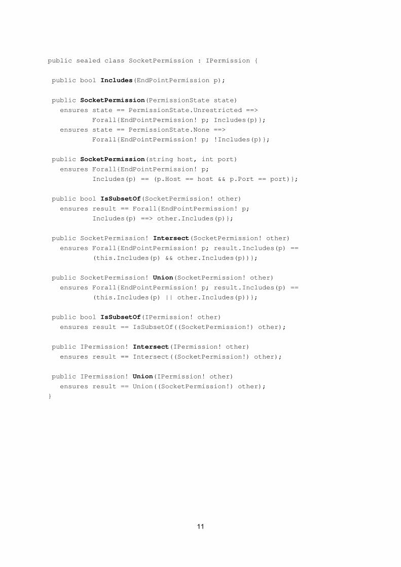
public sealed class SocketPermission : IPermission {
public bool Includes(EndPointPermission p);
public SocketPermission(PermissionState state)
ensures state == PermissionState.Unrestricted ==>
Forall{EndPointPermission! p; Includes(p)};
ensures state == PermissionState.None ==>
Forall{EndPointPermission! p; !Includes(p)};
public SocketPermission(string host, int port)
ensures Forall{EndPointPermission! p;
Includes(p) == (p.Host == host && p.Port == port)};
public bool IsSubsetOf(SocketPermission! other)
ensures result == Forall{EndPointPermission! p;
Includes(p) ==> other.Includes(p)};
public SocketPermission! Intersect(SocketPermission! other)
ensures Forall{EndPointPermission! p; result.Includes(p) ==
(this.Includes(p) && other.Includes(p))};
public SocketPermission! Union(SocketPermission! other)
ensures Forall{EndPointPermission! p; result.Includes(p) ==
(this.Includes(p) || other.Includes(p))};
public bool IsSubsetOf(IPermission! other)
ensures result == IsSubsetOf((SocketPermission!) other);
public IPermission! Intersect(IPermission! other)
ensures result == Intersect((SocketPermission!) other);
public IPermission! Union(IPermission! other)
ensures result == Union((SocketPermission!) other);
}
11
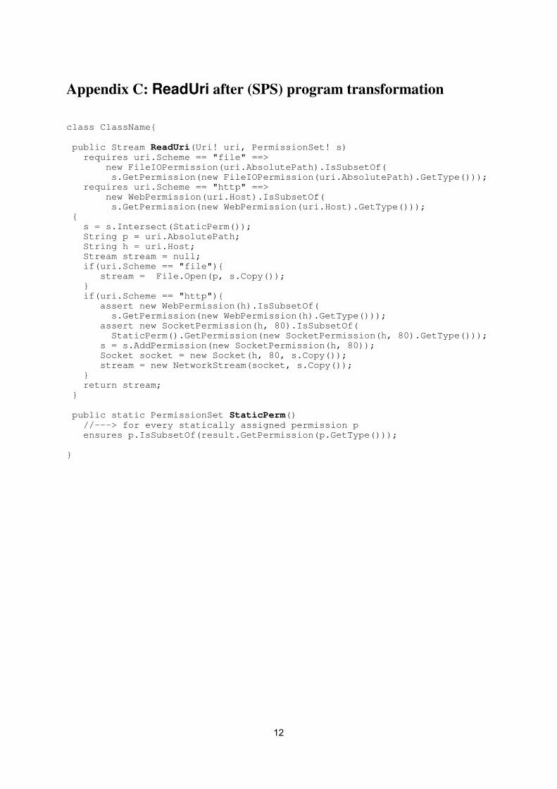
Appendix C: ReadUri after (SPS) program transformation class ClassName{ public Stream ReadUri(Uri! uri, PermissionSet! s) requires uri.Scheme == "file" ==> new FileIOPermission(uri.AbsolutePath).IsSubsetOf( s.GetPermission(new FileIOPermission(uri.AbsolutePath).GetType())); requires uri.Scheme == "http" ==> new WebPermission(uri.Host).IsSubsetOf( s.GetPermission(new WebPermission(uri.Host).GetType())); { s = s.Intersect(StaticPerm()); String p = uri.AbsolutePath; String h = uri.Host; Stream stream = null; if(uri.Scheme == "file"){ stream = File.Open(p, s.Copy()); } if(uri.Scheme == "http"){ assert new WebPermission(h).IsSubsetOf( s.GetPermission(new WebPermission(h).GetType())); assert new SocketPermission(h, 80).IsSubsetOf( StaticPerm().GetPermission(new SocketPermission(h, 80).GetType())); s = s.AddPermission(new SocketPermission(h, 80)); Socket socket = new Socket(h, 80, s.Copy()); stream = new NetworkStream(socket, s.Copy()); } return stream; } public static PermissionSet StaticPerm() //---> for every statically assigned permission p ensures p.IsSubsetOf(result.GetPermission(p.GetType())); }
12
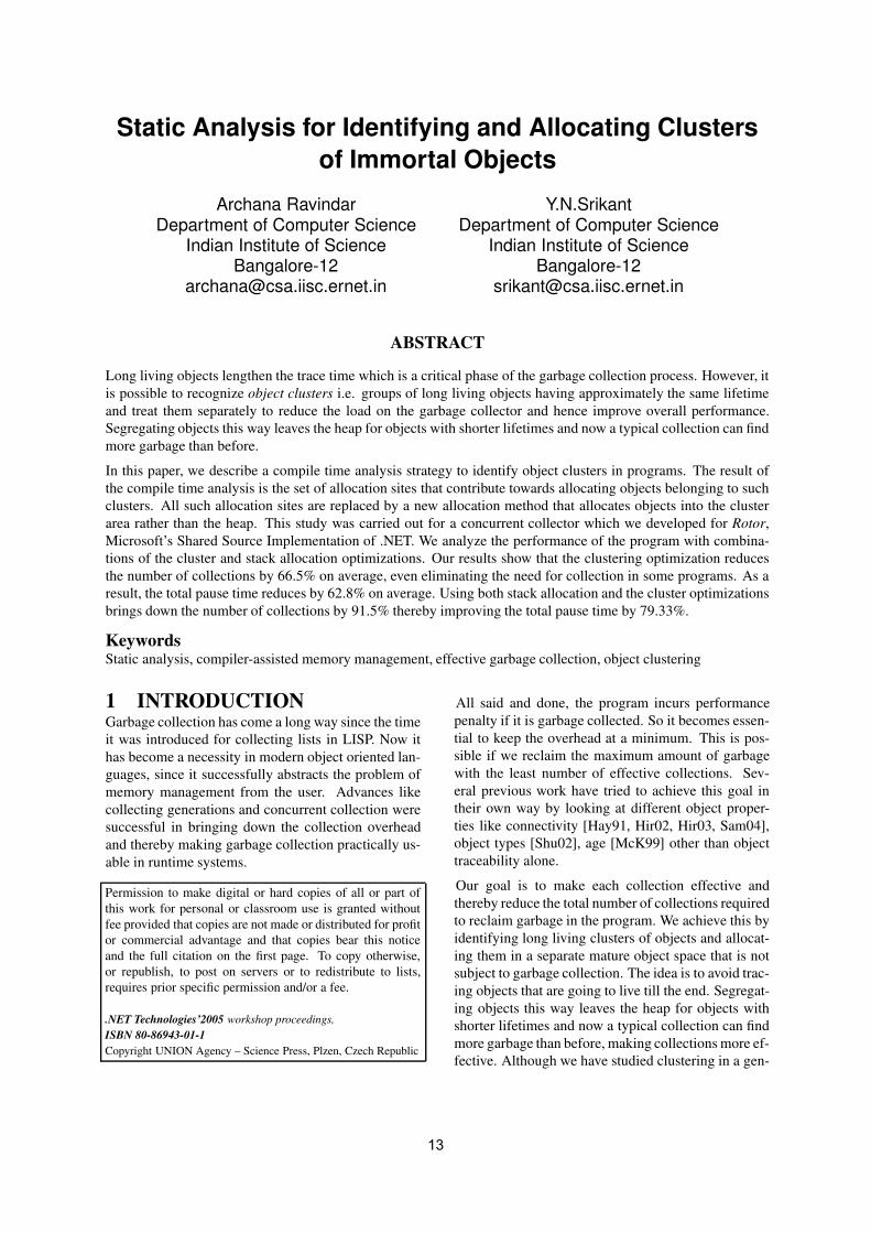
Static Analysis for Identifying and Allocating Clustersof Immortal Objects
Archana RavindarDepartment of Computer Science
Indian Institute of ScienceBangalore-12
Y.N.SrikantDepartment of Computer Science
Indian Institute of ScienceBangalore-12
ABSTRACT
Long living objects lengthen the trace time which is a critical phase of the garbage collection process. However, itis possible to recognize object clusters i.e. groups of long living objects having approximately the same lifetimeand treat them separately to reduce the load on the garbage collector and hence improve overall performance.Segregating objects this way leaves the heap for objects with shorter lifetimes and now a typical collection can findmore garbage than before.
In this paper, we describe a compile time analysis strategy to identify object clusters in programs. The result ofthe compile time analysis is the set of allocation sites that contribute towards allocating objects belonging to suchclusters. All such allocation sites are replaced by a new allocation method that allocates objects into the clusterarea rather than the heap. This study was carried out for a concurrent collector which we developed for Rotor,Microsoft’s Shared Source Implementation of .NET. We analyze the performance of the program with combina-tions of the cluster and stack allocation optimizations. Our results show that the clustering optimization reducesthe number of collections by 66.5% on average, even eliminating the need for collection in some programs. As aresult, the total pause time reduces by 62.8% on average. Using both stack allocation and the cluster optimizationsbrings down the number of collections by 91.5% thereby improving the total pause time by 79.33%.
KeywordsStatic analysis, compiler-assisted memory management, effective garbage collection, object clustering
1 INTRODUCTIONGarbage collection has come a long way since the timeit was introduced for collecting lists in LISP. Now ithas become a necessity in modern object oriented lan-guages, since it successfully abstracts the problem ofmemory management from the user. Advances likecollecting generations and concurrent collection weresuccessful in bringing down the collection overheadand thereby making garbage collection practically us-able in runtime systems.
Permission to make digital or hard copies of all or part ofthis work for personal or classroom use is granted withoutfee provided that copies are not made or distributed for profitor commercial advantage and that copies bear this noticeand the full citation on the first page. To copy otherwise,or republish, to post on servers or to redistribute to lists,requires prior specific permission and/or a fee.
.NET Technologies’2005 workshop proceedings,ISBN 80-86943-01-1Copyright UNION Agency – Science Press, Plzen, Czech Republic
All said and done, the program incurs performancepenalty if it is garbage collected. So it becomes essen-tial to keep the overhead at a minimum. This is pos-sible if we reclaim the maximum amount of garbagewith the least number of effective collections. Sev-eral previous work have tried to achieve this goal intheir own way by looking at different object proper-ties like connectivity [Hay91, Hir02, Hir03, Sam04],object types [Shu02], age [McK99] other than objecttraceability alone.
Our goal is to make each collection effective andthereby reduce the total number of collections requiredto reclaim garbage in the program. We achieve this byidentifying long living clusters of objects and allocat-ing them in a separate mature object space that is notsubject to garbage collection. The idea is to avoid trac-ing objects that are going to live till the end. Segregat-ing objects this way leaves the heap for objects withshorter lifetimes and now a typical collection can findmore garbage than before, making collections more ef-fective. Although we have studied clustering in a gen-
13

erational setting this elementary concept is applicableto incremental collectors too.
This paper describes a compile time clustering analy-sis algorithm based on the compositional pointer andescape analysis framework proposed in [Wha99]. Theclustering algorithm makes use of the lifetime in-formation of objects computed by the points to es-cape analysis algorithm, that is constructed for everymethod. The objects that do not escape the longestliving methods are designated as the root of the clus-ter. The objects that are reachable from the root aretreated as cluster objects. All such cluster objects arestatically allocated in a separate mature object space.When the stack frame of the method binding the life-time of the root object is popped, the entire cluster isgarbage and hence the mature object space can be re-claimed in its entirety.
The clustering scheme is evaluated using a base-line collector that can run in both stop-the-world andconcurrent modes that we developed for Rotor, Mi-crosoft’s shared source implementation of .NET. Thebaseline collector has two generations and uses thecopying scheme to collect both. We analyze the per-formance of the collector and the program with thecluster and the stack allocation optimizations. Our re-sults show a marked decrease in the total number ofcollections and considerable improvement in the indi-vidual collection performance. It is observed that acombination of the clustering and the stack allocationoptimization improves the performance even further.
The remainder of the paper is organized as follows.We begin by reviewing related work in Section 2. Sec-tion 3 describes the concept of clustering and how weextend the compositional pointer and escape analysisto identify clusters. In Section 4 we describe the base-line collector and the experimental platform. In Sec-tion 5 we present and evaluate the results. Finally weconclude in section 6 with possible avenues of futurework.
2 RELATED WORKHayes introduced the term object clustering [Hay91].The main observation was that large clusters of ob-jects, pointed to by key objects were allocated atroughly the same time and lived for approximately thesame amount of time. When the key objects becameunreachable it indicated a good opportunity to collect.Hayes identified the cluster as the program executedand incrementally placed it in the mature object space.Our work tries to identify the cluster at compile timeand statically allocates the cluster into the mature ob-ject space. The compile time clustering algorithm isused to find key objects. Unlike Hayes’s scheme where
the mature object space is collected, we do not sub-ject the mature object space to garbage collection. Wecombine the concepts of escape analysis and cluster-ing to reclaim the cluster.
Pretenuring tries to solve the problem of repeated col-lections of long living objects by directly allocatingsuch objects into the old generation by using static anddynamic profiles [Bla98, Che98, Har00]. But the oldgeneration is still subject to collection, so in spite ofapplying the pretenuring optimization, major collec-tions might still occur. Our scheme tries to completelyeliminate major collections by allocating these longliving or immortal objects in a separate mature objectspace that is not subject to collection.
Dynamic object colocation [Sam04] allocates objectsdirectly into the same area of an object that will ref-erence it, by using a mix of compile-time and runtimeoptimizations. Static compiler analysis is used to com-pute connectivity information and the runtime compo-nent involves an allocation routine which takes a colo-cator object as an additional parameter and is respon-sible for dynamic colocation. The dynamic colocatorcan start placing objects into the mature object spaceonly when some initial set of colocators are present.Hence it requires a warm up young generation collec-tion to produce these initial colocators, whereas theintention of our scheme is to reduce the number ofcollections, even eliminating the need for collectionif possible. [Sam04] reports a considerable increase inthe number of intergenerational pointers for some ofits programs. Our results indicate that clustering onlyreduces the number of intergenerational pointers butnever increases it.
Connectivity based garbage collection makes use ofthe observation that connected objects die together.Based on this hypothesis it allocates objects that areconnected together into a statically determined parti-tion so that collecting a partition would be much fasterthan collecting the heap. [Hir03] works by buildinga hierarchy of partition dags and collects these parti-tions such that an ancestor is collected together with itsdescendants thereby eliminating the need for a write-barrier.
3 CLUSTERINGThe concept of data is fundamental to every program.Programs feed on data, they build several data struc-tures that assist them in performing their functional-ity. In the object oriented paradigm, objects store data.These data objects are seldom isolated, rather they arerelated to one another in some way and hence linkedtogether to form clusters.
Most often a program is associated with a set of crit-
14

ical objects that are bound to stay till almost the endof the program. Such objects are said to be immor-tal. If these objects are treated in the same way as thedefault heap objects, they would unnecessarily be pro-cessed by the garbage collector, resulting in increasedcollection times. Figure 1 illustrates the impact of longliving objects on the total collection time, measured asthe fraction of time spent in scavenging live objects.We observe that the scavenge time accounts for a sig-nificant fraction of the total collection time (up to 83%in 211 anagram). Further investigation reveals thatup to 88% of the objects were found to be live duringthe collection. Hence tracing immortal or long livingclusters plays a major role in lengthening the total col-lection time.
Figure 1: Proportion of Collection Time spent onScavenge.
If we can recognize the allocation sites in the programresponsible for creating long living clusters (high-lighted in Figure 2) at compile time, we can staticallyallocate them in a region that is not processed by thegarbage collector. The region can then be reclaimedin its entirety at program termination. Such a strat-egy allows the garbage collector to focus on objectsthat are volatile and objects whose lifetimes cannot bestatically determined. We describe the clustering algo-rithm which identifies long living clusters in the nextsection.
Extending Compositional Pointer AnalysisTo Identify ClustersThe algorithm to identify clusters in a program isbased on the compositional and pointer escape anal-ysis proposed for Java programs by Whaley and Ri-nard [Wha99]. The referencing behavior among ob-jects and fields is abstracted in the form of a points-
Figure 2: Set of Allocation Sites that contribute to-wards Cluster Objects in 211 anagram
to-escape or the PTE graph. Nodes in the PTE graphrepresent objects allocated by the program and edgesrepresent references between them. Objects that arecreated within the currently analyzed region are rep-resented by inside nodes in the PTE graph, whereasthose created outside the currently analyzed region oraccessed via outside edges are represented by outsidenodes in the PTE graph. Similarly inside edges repre-sent references created within the currently analyzedregion. References created outside the currently ana-lyzed region are represented by outside edges in thePTE graph. We restrict our analysis to programs thatare single-threaded.
The algorithm is compositional in nature i.e. meth-ods can be analyzed independently of their callers andcallees. [Wha99] describes an intra-procedural algo-rithm that computes individual PTE graphs for eachmethod and an inter-procedural algorithm that com-putes precise points-to-escape information for eachmethod. The inter-procedural algorithm combines thePTE graph for each method with the PTE graphs cre-ated for all its callees.
The ultimate objective of the algorithm is to determinefor every allocation site A, the method M whose stackframe will outlive the object created at A. In such asituation, object created at A is said to be captured by
15

M. If enough information is not available to ascertainwhether an object escapes or not, it is allocated in theheap.
An object is said to have escaped a method M if it isa formal parameter or if a reference to the object iswritten into a static class variable or a reference to theobject is passed to one of the callees of M say N andthere is no information available about what N did tothe object. The object will escape if M returns it. If theobject satisfies none of the above conditions it is saidto be captured within M.
In essence, when a complete points-to escape analysisgraph is constructed for a method M it consists of thenodes that were either created within the method M ornodes created outside M but are reachable from withinM. The clustering algorithm makes use of this fact torecognize a cluster.
3.1.1 DesignIn this section we describe the clustering algorithmin the form of pseudocode as shown in Figures 3and 4. To begin with, we need to preprocess thestatements to include only those that will affect thePTE graph [Wha99]. The csharp compiler invokesCompileMethod for every method, that creates basicblocks, while it translates the source code into op-codes. We intercept at points where code is generatedfor statements that we are interested in and save thedetails of the statement in a separate data structure.
Once the code for the method is generated, we iter-ate through the statements that we created to computethe PTE graph. The graph is implemented as an adja-cency list. Each node is a structure that stores the setof incoming and outgoing edges, node kind and infor-mation whether it was visited or not. Each edge is astructure that stores the head and the tail node, edgekind and the variable it represents.
During the intra-procedural analysis, when we en-counter a call statement it is possible that the PTEgraph for that call is not yet computed. The status ofall such statements that have incomplete informationis marked as pending. During the inter-proceduralanalysis we process only pending statements to com-pute the complete PTE graph. Finally, we process thePTE graphs of only those methods M that lie closeto main in the call graph, to compute cluster informa-tion. This list of methods can be got by profiling. ThePTE graph for all such M would consist of only thosenodes that have escaped up to M, since they are reach-able from within M. All other nodes that have beencaptured within methods lying below M would not bevisible in the PTE graph for M. Hence the cluster al-gorithm correctly identifies only those objects that aregoing to live till the stack frame of M has been popped
off and is bound to benefit the collection process.
The marked nodes in M which are not pointed to byany other node in the PTE graph of M are said to bethe roots of the cluster. They serve the same functionas the key objects because they are the only way toreach a cluster. When the key object is garbage, allthe objects connected to it are dead. Hence when thestack frame for method M is popped, the root objectand hence the entire cluster associated with it is deadand can therefore be reclaimed.
The clustering analysis algorithm is conservative inthe sense that some of the objects belonging to thecluster might die before the stack frame containing theroot of the cluster is popped. This is especially truein cases where a dynamically growing structure likea stack or a list is part of the cluster. However, weshall shortly see that even this naive approach of iden-tifying a clusters performs reasonably well for mostprograms.
Figure 3: Pseudocode for Inter and Intra procedu-ral analysis
3.1.2 ExampleFigure 5 shows the local PTE graphs for two of themethods in 211 anagram. In the PTE graph for
16

Figure 4: Pseudocode for identifying Clusters
Figure 5: Identifying clusters using PTE graphs.
read file, sif is captured. Despite being a local ob-ject, istr is linked to the dict variable by the librarycall dict.Add and hence becomes a part of the clus-ter. Since the reference is added outside the method,it is indicated as an outside edge. The intra-proceduralanalysis for read file deems all nodes except sif asescaped. The dotted line in Figure 5 indicates howthe nodes in run will be mapped onto the nodes of thecallee read file during inter-procedural analysis.Interprocedural analysis is followed by the applicationof the clustering algorithm as described earlier, thatmarks all the nodes in the graph that corresponds to thecluster allocation sites. In this particular example, theclustering algorithm accesses the complete PTE graphof run and marks all nodes reachable from the noderepresenting agm as cluster nodes. agm is designatedas the root of the cluster. Since by definition each nodeis associated with an object and hence with an alloca-tion site producing that object, one can output the setof allocation sites responsible for cluster allocation.
The fact that the analysis is compositional makes it
possible to analyze libraries independently of the ap-plication. When analyzing an application, we use pre-computed results for any library calls that it may make.Since the clustering algorithm can access the precom-puted results for the library calls, it is possible forthe algorithm to come up with cluster allocation siteswithin the library code, as we saw dict.Add in Figure5. To support clustering completely, we create a newlibrary that consists of additional functions to supportcluster allocation.
Other changes to Rotor for implementing the cluster-ing scheme include the introduction of two new op-codes newclus and newst that are wired to perform al-location in the cluster and in the stack respectively. Inthis implementation, we have simulated the allocationon the stack using a separate area apart from the heapand the cluster area. To measure the impact of sim-ulating the stack allocation we ran the programs witha maximum heap size (so that there was no garbagecollection) and compared the elapsed times with thebaseline which has no stack allocation implemented.On average, the overhead of stack implementation wasfound to be -2.1%.
3.1.3 Issue with BoxingIn any implementation of CLI, when an instance of avalue type is passed as a parameter to a method thatexpects a reference parameter, boxing is performed[Ecm03]. Boxed objects are implicit and are not ev-ident in csharp source code. Since the clustering algo-rithm works on the source code, it does not have a han-dle to the boxed objects. Our implementation tacklesthis problem by converting implicit boxing to explicitboxing. We overload the existing methods that takea reference as a parameter, to take value types also.These additional methods now include code that per-forms explicit boxing. So now the clustering algorithmcan access the boxed objects and include them in theanalysis.
4 METHODOLOGYBaseline CollectorThe baseline collector is designed to work on the prin-ciples of concurrent replication collection [Too93].It consists of two generations. The young genera-tion is also known as newspace. This is where allthe new objects are allocated. The old generationis comprised of two semispaces- fromspace and thetospace. Copying collection is used to collect bothgenerations. When allocation in the newspace crossesa particular threshold, a minor collection is invokedthat scavenges the live objects into fromspace. Even-tually the fromspace gets filled up to its thresholdvalue which invokes a major collection that collects
17

Figure 6: Baseline Collector Organization withClustering Incorporated.
the entire heap.
Scavenging is a concurrent operation, hence the pro-gram and the collector thread need to be synchronizedto ensure that things work correctly. Our approach forsynchronizing the program and the collector is an ex-tension of the Dijkstra’s tricolor scheme. We associateeach object with a color that is used to indicate ob-ject state information to both the collector and the pro-gram. The details of the synchronization scheme canbe found in [Rav05].
All generational collectors are associated with a writebarrier [Hos92], that is a piece of code executed withevery pointer write. We add the synchronization codeto the write barrier to support concurrency in the col-lector. The baseline collector supports finalization,weak pointers and interior pointers. However, unlikethe rotor garbage collector, it does not support largeobjects allocation and pinning. Incorporating cluster-ing into the garbage collector adds a new mature objectspace to the existing heap. The baseline collector canalso run in the stop-the-world mode. The final memorymodel of the collector is as shown in Figure 6.
Experimental PlatformThis study was conducted on Rotor version 1.0 [Rot01].We ran the programs on an Intel pentium III 450 Mhzprocessor with 128MB of main memory and a 512KBcache, running Free BSD 4.5.
5 RESULTSIn this section, we evaluate the baseline collector bycomparing its performance with Rotor’s garbage col-lector. We evaluate the clustering optimization w.r.t.the collector and program performance. We also studythe impact of the stack allocation optimization alongwith the clustering optimization. To carry out thisstudy, we used the C# versions of the Java programsfrom Spec JVM98 [Spc98], Java olden [Jolden], Javagrande [Jgrande] and the gc test suite provided withRotor [Rot01]. The benchmarks and their runtime pa-rameters are summarized in Table 1.
Performance of the Concurrent CollectorIn this section we describe the performance of thebaseline collector w.r.t. pause times and elapsed times.The results for both the stop the world and concurrentmodes are presented. The heap sizes are chosen suchthat both the Rotor garbage collector and the baselinecollector have the same number of collections.
5.1.1 Pause TimeThe main objective for choosing a concurrent gc algo-rithm for the baseline collector was to reduce the pausetimes. Almost all the programs report significant re-ductions in pause times for the concurrent mode, ex-cept for raytrace which shows an increase of 4.62%.The average reduction in pause times for the concur-rent mode is 36.24%. However pause times increaseby 2.14% on average when the collector is run in thestop-the-world mode.
5.1.2 Elapsed TimeThe baseline collector introduces a very small over-head of 1.11% when run in the stop-the-world mode.However, the overhead is slightly worse in the concur-rent mode. That is because of the additional synchro-nization code that needs to be executed. The averageoverhead on the elapsed time is 1.75% for the concur-rent mode. It can be observed that in spite of a substan-tial improvement in the pause time, the elapsed timesdo not change by much. That is because the collectiontime constitutes a very small portion of the elapsedtime.
Performance of ClusteringIn this section we describe the performance of the pro-grams when the clustering optimization and the stackallocation optimizations are performed. The programsare run with the heap sizes as shown in Table 2. Clus-tering reduces the total heap requirement by 12.6% onaverage.
5.2.1 Reduction in the Number of CollectionsBoth clustering and the stack allocation optimizationsare geared towards reducing the load on the garbagecollector. For certain programs where the total popula-tion of objects is dominated by clusters, clustering op-timization yields a lot of benefit. For programs wherevolatile objects dominate, stack allocation yields sim-ilar benefit. The average reduction in the number ofcollections for programs where only the stack allo-cation optimization and the clustering optimization isused is 75% and 66.5% respectively. A combinationof the stack and cluster allocation yields the highestreduction of collections at 91.56%. The results are thesame for the collector when operated in the concurrentmode.
18

Source Program Runtime parametersRotor gc test suite directedgraph No. of vertices=100
Spec JVM98 208 cst No of iterations=1, speed=1209 db No. of iterations=1, Speed=10
211 anagram Speed=1210 si Speed=10
Java Olden bisort No of nodes=4, size=2500jhealth MaxLevel=5, MaxTime=100, seed=23power No of feeders= 5, No of laterals= 10,
No of branches= 3, No of leaves= 5tsp Size= 600
treeadd No of levels=16Java Grande raytrace Width= 25, height= 25
Table 1: Set of Benchmarks used and their Configuration
Program Young gen Old gen Young gen Old gen Max Cluster Sizesize (MB) size (MB) with clustering (MB) with clustering (MB) (MB)
211 anagram 2 8 0.7 1.4 3.8209 db 1 10 1 2 2.5210 si 1 2 1 2 0.9bisort 1 2 1 2 0.05jhealth 1 2 0.3 0.6 2.6208 cst 1 40 0.7 1.4 12.7power 1 2 0.3 0.6 0.07
tsp 1 2 0.7 1.4 0.05raytrace 0.8 1.6 0.8 1.6 3.6
directedgraph 1 2 1 2 0.15treeadd 4 8 0.19 0.38 1.4
Table 2: Heap and Mature Object Space sizes
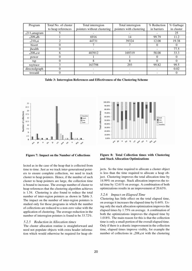
5.2.2 Reduction in Collection and Pause TimesOne of the direct consequences of the reduction in thenumber of collections is the reduction in the total col-lection time and the total pause time. Reduction in thenumber of objects scavenged also contributes to reduc-tion in the collection time. The average reduction inthe total collection time using only the stack allocationoptimization is 60.9%; with only the cluster optimiza-tion it is about 60.6%; with both optimizations on, thereduction is about 79.27%. The corresponding averagereductions in the pause times are 63.55% with only thestack allocation optimization, 62.82% with only thecluster optimization and 79.33% with both optimiza-tions applied.
When the collector operates in the concurrent mode,the average reductions in pause times are 60.09%,60.9% and 79.27% with only the stack allocation, onlythe clustering optimization and both optimizations ap-plied respectively.
5.2.3 Reduction in Copycounts
Once the clustering optimization is done, there isgreater chance for a collection to find more garbagethan earlier. Since the long living clusters are ex-empted from collection, only those objects that are rel-atively volatile remain in the heap. This causes a re-duction in the number of objects copied. Copy countscan also reduce due to the reduction in the number ofcollections as we saw in the previous section. Copycounts reduce by almost 60.11% with only the stack al-location optimization applied and by 91.37% with thecluster optimization applied. A combination of bothreduces the copy counts further by 94.02%. The re-sults are almost the same for the collector when oper-ated in the concurrent mode.
5.2.4 Impact on Inter-region ReferencesA profile of the inter-region references indicate veryminimal interaction between the cluster objects andthe heap objects (Table 3). The number of such clus-ter to heap pointers is critical to the success of cluster-ing. The cluster is reclaimed in its entirety and not col-
19
Program Total No. of cluster Total interregion Total interregion % Reduction % Garbageto heap references pointers without clustering pointers with clustering in barriers in cluster
211 anagram 5 - - - 25209 db 1 6916 14 99.79 11.2210 si 2 44731 39324 12.08 19.38bisort 0 7 7 0 0jhealth 0 - - - 77.5208 cst 6 403912 169319 58.08 33.3power 0 1 1 0 0
tsp 0 8 8 0 0raytrace 3 163798 293 99.82 99.5
directedgraph 0 - - - 0.02treeadd 0 - - - 0
Table 3: Interregion References and Effectiveness of the Clustering Scheme
Figure 7: Impact on the Number of Collections
lected as in the case of the heap that is collected fromtime to time. Just as we track inter-generational point-ers to ensure complete collection, we need to trackcluster to heap pointers. Hence, if the number of suchcluster to heap pointers are large, the collection timeis bound to increase. The average number of cluster toheap references that the clustering algorithm achievesis 1.54. Clustering is also found to reduce the totalnumber of inter-region pointers as shown in Table 3.The impact on the number of inter-region pointers isstudied only for those programs in which the numberof collections are reduced to a non-zero value with theapplication of clustering. The average reduction in thenumber of interregion pointers is found to be 33.72%.
5.2.5 Reduction in Allocation timesThe cluster allocation routine is straightforward andneed not populate objects with extra header informa-tion which would otherwise be required for heap ob-
Figure 8: Total Collection times with Clusteringand Stack Allocation Optimizations
jects. So the time required to allocate a cluster objectis less than the time required to allocate a heap ob-ject. Clustering improves the total allocation time by14.99% on average. Stack allocation improves the to-tal time by 12.61% on average. A combination of bothoptimizations results in an improvement of 20.63%.
5.2.6 Impact on Elapsed TimeClustering has little effect on the total elapsed time,on average it increases the elapsed time by 0.44%. Us-ing only the stack allocation optimization improves theelapsed times by 1.75% on average. A combination ofboth the optimizations improves the elapsed time by1.018%. The main reason for this is that the collectiontime is only a small portion of the overall elapsed time.Only if there is a drastic improvement in the collectiontime, elapsed times improve visibly, for example thenumber of collections in 208 cst with the clustering
20

Figure 9: Total Copy Counts with Clustering andStack Allocation Optimizations
optimization decreases from 23 to 11. Hence, in thiscase the elapsed time reduces by 12.19%. The otherreason is that the addition of a separate cluster area in-troduces overheads w.r.t. the elapsed time. Since anobject can now reside in the cluster area apart from theheap, the garbage collector code needs to recognizeobjects in the cluster area and also in the stack, if thestack allocation optimization is applied.
Additional barrier code to keep track of cluster to heappointers also contributes to increased elapsed times.The effect on elapsed time is more or less the same forthe concurrent mode. Using just the escape analysisoptimization, the average elapsed times decrease byonly 0.377%; clustering increases the elapsed times by1.19%. Using both optimizations the average elapsedtime decreases by 0.59%
Figure 10: Impact of the Clustering and Stack Al-location Optimizations on the Elapsed Time
5.2.7 Effectiveness of the Clustering AlgorithmTo evaluate the effectiveness of the clustering algo-rithm and to verify its claim of retaining genuinelylong living objects right up to the end, additional in-strumentation is added to the code. At the time ofreclamation of the cluster area, instead of freeing itup, the cluster area is collected to find the amountof garbage generated within itself. The amount ofgarbage generated in the cluster using our algorithmis found to be 24.17% on average. Ideally it should be0%.
The clustering algorithm presented here does not cap-ture dynamic growth of clusters. More complexpointer analysis is required to come up with an idealcluster. Since the clustering algorithm is by naturestatic, Allocation site homogeneity is an issue. Forexample raytrace includes an allocation site that iscalled in two different contexts. In one it creates a cap-tured object, in the other it creates a cluster object. Ifwe decide to allocate the object in the heap, the num-ber of cluster to heap references shoot up, thereby de-grading the performance of the collector. On the otherhand, if we decide to cluster allocate the object, hugeamount of garbage would be generated within the clus-ter area due to the volatile nature of the object. In suchcases dynamic object colocation [Sam04] might per-form better since it makes colocation decisions on thefly at runtime.
6 CONCLUSIONSFor a garbage collector to work effectively, it has to beaware of object properties and not just object traceabil-ity. The compiler plays an important role in provid-ing valuable information about object properties to thegarbage collector. This paper describes and evaluatesa compile time technique that recognizes clusters in aprogram and statically allocates cluster objects sepa-rately. Our results demonstrate that the clustering op-timization reduces the number of collections consider-ably and also improves the individual collection timesby a fairly large amount. When applied along with thestack allocation optimization it produces even betterresults. Clustering also improves the total number ofinterregion pointers. However, elapsed times do notimprove in the same vein as the collection times. Onlythose programs in which there is a drastic reductionin the number of collections show a considerable im-provement in the elapsed time.
Future WorkOur work can be extended in several directions. Thecurrent clustering algorithm identifies clusters that arecreated only in those methods that have the longest
21

lifetimes. One can extend the clustering concept toall other methods to discover scoped memory regions.The current compiler analysis itself can be made moresophisticated so that it not only outputs the allocationsites but also provides information to the programmerwhether the cluster optimization would prove benefi-cial for that program or not. Several parameters areindicative of whether a cluster would prove as an ad-vantage or as a penalty. Some of them are the num-ber of cluster to heap references, allocation site homo-geneity, the fraction of the objects that are allocatedin the cluster, dynamic growth of clusters that mightcontribute garbage within the cluster area. However,the compiler would require complex pointer analysisto infer some of this information. Allocating clusterobjects in a separate area brings in the need for addi-tional barrier code to track cluster to heap references.Static analysis can be used to eliminate the write barri-ers wherever unnecessary and hence improve elapsedtimes.
7 ACKNOWLEDGEMENTSThis work was funded by Microsoft Research. Wethank the anonymous reviewers for their commentsand suggestions.
References[App89] A.Appel, Simple generational garbage collection
and fast allocation. Software: Practice and Experience,19(2):171-183, Feb 1989.
[Bla98] S. M. Blackburn, S. Singhai, M. Hertz, K. S.McKinley, and J. E. B. Moss. Pretenuring for Java.In ACM Conference on Object-Oriented ProgrammingSystems, Languages, and Applications, pages 342-352,Tampa, FL, Oct. 2001. ACM.
[Che98] P.Cheng, R. Harper and P. Lee, Generational stackcollection and profile-driven pretenuring. In ACM Con-ference on Programming Languages Design and Im-plementation, pages 162-173, Montreal, Canada, May1998.
[Det02] Morgan Deters and Ron K. Cytron, AutomatedDiscovery of Scoped Memory Regions for Real-TimeJava. In ACM International Symposium on MemoryManagement, pages 25-35, Berlin, Germany, June 2002.
[Ecm03] ECMA C# and Common Language InfrastructureStandards. http://msdn.microsoft.com/net/ecma/
[Gay01] D. Gay and A. Aiken. Language Support for Re-gions. In Proceedings of the ACM SIGPLAN ’01 Con-ference on Programming Language Design and Imple-mentation, pages 70-80, 2001.
[Har00] T. L. Harris. Dynamic adaptive pre-tenuring. InACM International Symposium on Memory Manage-ment, pages 127-136, Minneapolis, MN, Oct. 2000.
[Hay91] Barry Hayes. Using key object opportunism to col-lect old objects. In Object-Oriented Programming, Sys-tems, Languages, and Applications (OOPSLA), 1991.
[Hir02] M.Hirzel, J.Hinkel, A.Diwan and M.Hind, Under-standing the connectivity of heap objects. In ACM In-ternational Symposium on Memory Management, pages36-49, Berlin, Germany, June 2002.
[Hir03] M.Hirzel, A.Diwan and M.Hertz. Connectivitybased garbage collection. In ACM Conference on Ob-ject Oriented Programming Systems , Languages andApplications, pages 359-373,Anaheim, CA, Oct 2003.
[Hos92] Antony L. Hosking, J. Eliot B. Moss and DarkoStefanovic, A comparative performance evaluation ofwrite barrier implementations. In ACM Conferenceon Object-Oriented Programming Systems, Languages,and Applications, pages 92-109, 1992
[Jgrande] http://www.epcc.ed.ac.uk/javagrande[Jolden] Brenden Cahoon, Java Olden benchmarks,
http://www.cs.utexas.edu/users/cahoon/[Lie83] H. Lieberman and C. E. Hewitt. A real time garbage
collector based on the lifetimes of objects. Communica-tions of the ACM, 26(6):419-429, 1983.
[McK99] D. Stefanovic, K. McKinley, and J. Moss. Age-based garbage collection. In ACM Conference onObject-Oriented Programming Systems, Languages,and Applications, pages 370-381, Denver, CO, Nov.1999.
[Rav05] Archana Ravindar and Y.N.Srikant. Design andImplementation of a Concurrent Garbage Collector forRotor. Technical Report IISc-CSA-TR-2005-2, Dept ofComputer Science and Automation, IISc.
[Rot01] http://www.sscli.net[Rug87] Cristina Ruggieri and Thomas P. Murtagh. Life-
time Analysis of Dynamically Allocated Objects, pages285-293, ACM SIGPLAN’88
[Sam04] Samuel Z. Guyer and Kathryn S. Mckinley. Find-ing Your Cronies: Static Analysis for Dynamic Coloca-tion. In ACM Conference on Object-Oriented Program-ming Systems, Languages, and Applications, pages237-250, Vancouver, British Columbia, Canada, Octo-ber 2004.
[Shu02] Y. Shuf, M. Gupta, R. Bordawekar, and J. P. Singh.Exploiting prolific types for memory management andoptimizations. In ACM Symposium on the Principles ofProgramming Languages, pages 295-306, Portland, OR,Jan. 2002.
[Spc98] http://www.spec.org/osg/jvm98[Stu03] David Stutz, Ted Neward and Geoff Shilling.
Shared Source CLI Essentials.[Too93] James O’ Toole and Scott Nettles. Concurrent
Replicating Garbage Collection. In ACM Symposiumon LISP and Functional Programming
[Wha99] John Whaley and Martin Rinard. CompositionalPointer and Escape Analysis for Java Programs, In ACMConference on Object-Oriented Programming Systems,Languages, and Applications, pages 187-206, Denver,CO, Nov. 1999.
22
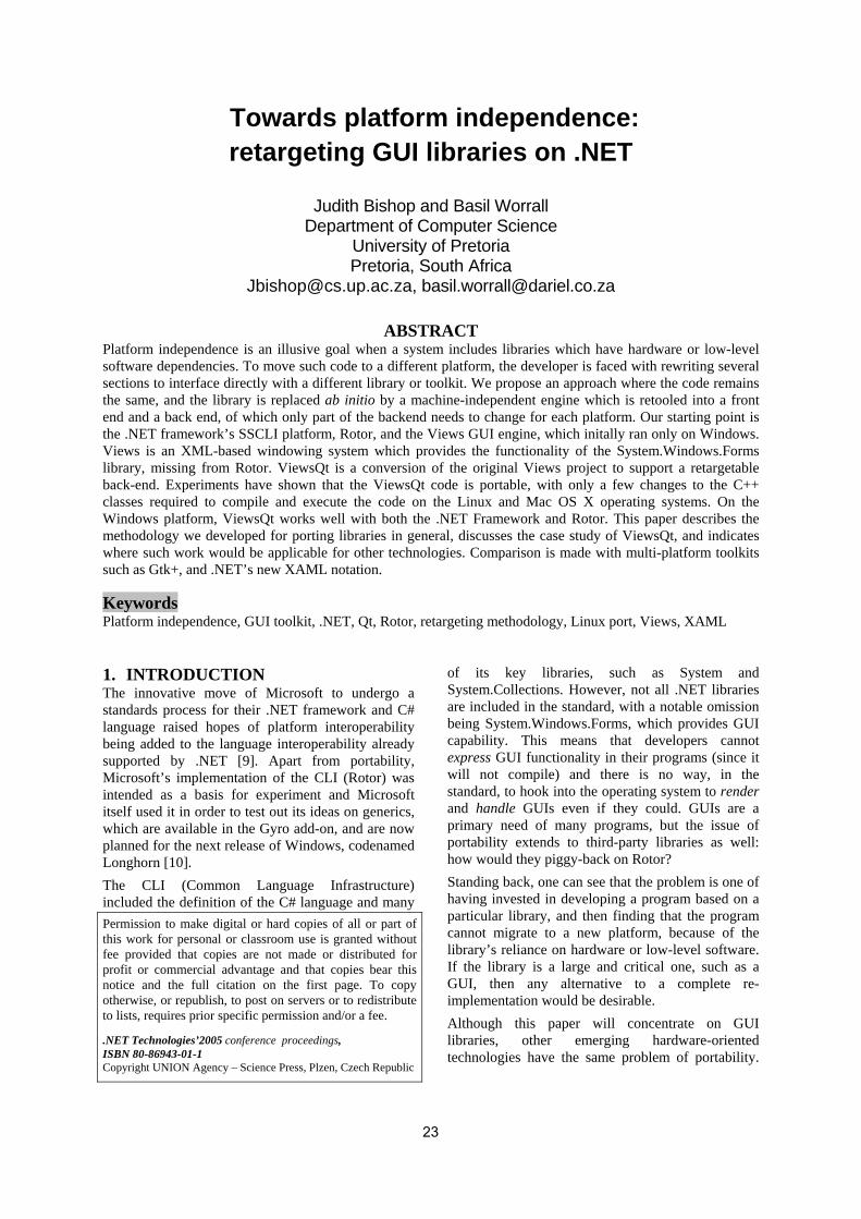
Towards platform independence: retargeting GUI libraries on .NET
Judith Bishop and Basil Worrall
Department of Computer Science University of Pretoria Pretoria, South Africa
[email protected], [email protected]
ABSTRACT Platform independence is an illusive goal when a system includes libraries which have hardware or low-level software dependencies. To move such code to a different platform, the developer is faced with rewriting several sections to interface directly with a different library or toolkit. We propose an approach where the code remains the same, and the library is replaced ab initio by a machine-independent engine which is retooled into a front end and a back end, of which only part of the backend needs to change for each platform. Our starting point is the .NET framework’s SSCLI platform, Rotor, and the Views GUI engine, which initally ran only on Windows. Views is an XML-based windowing system which provides the functionality of the System.Windows.Forms library, missing from Rotor. ViewsQt is a conversion of the original Views project to support a retargetable back-end. Experiments have shown that the ViewsQt code is portable, with only a few changes to the C++ classes required to compile and execute the code on the Linux and Mac OS X operating systems. On the Windows platform, ViewsQt works well with both the .NET Framework and Rotor. This paper describes the methodology we developed for porting libraries in general, discusses the case study of ViewsQt, and indicates where such work would be applicable for other technologies. Comparison is made with multi-platform toolkits such as Gtk+, and .NET’s new XAML notation.
Keywords Platform independence, GUI toolkit, .NET, Qt, Rotor, retargeting methodology, Linux port, Views, XAML
1. INTRODUCTION The innovative move of Microsoft to undergo a standards process for their .NET framework and C# language raised hopes of platform interoperability being added to the language interoperability already supported by .NET [9]. Apart from portability, Microsoft’s implementation of the CLI (Rotor) was intended as a basis for experiment and Microsoft itself used it in order to test out its ideas on generics, which are available in the Gyro add-on, and are now planned for the next release of Windows, codenamed Longhorn [10]. The CLI (Common Language Infrastructure) included the definition of the C# language and many
of its key libraries, such as System and System.Collections. However, not all .NET libraries are included in the standard, with a notable omission being System.Windows.Forms, which provides GUI capability. This means that developers cannot express GUI functionality in their programs (since it will not compile) and there is no way, in the standard, to hook into the operating system to render and handle GUIs even if they could. GUIs are a primary need of many programs, but the issue of portability extends to third-party libraries as well: how would they piggy-back on Rotor? Standing back, one can see that the problem is one of having invested in developing a program based on a particular library, and then finding that the program cannot migrate to a new platform, because of the library’s reliance on hardware or low-level software. If the library is a large and critical one, such as a GUI, then any alternative to a complete re-implementation would be desirable. Although this paper will concentrate on GUI libraries, other emerging hardware-oriented technologies have the same problem of portability.
Permission to make digital or hard copies of all or part of this work for personal or classroom use is granted without fee provided that copies are not made or distributed for profit or commercial advantage and that copies bear this notice and the full citation on the first page. To copy otherwise, or republish, to post on servers or to redistribute to lists, requires prior specific permission and/or a fee. .NET Technologies’2005 conference proceedings, ISBN 80-86943-01-1 Copyright UNION Agency – Science Press, Plzen, Czech Republic
23

Among these are tangible user interfaces (TUIs) and mobile applications. TUIs integrate digital information with everyday physical objects such as electronic tags and barcodes. Papier-Mâché [11] is an open-source toolkit for building TUIs with a high-level event model to facilitate portability. CrossFire [12] is a third-party product built on top of .NET. Crossfire uses a booster to the CLR to enable code in VB to run on the compact frameworks used by a variety of mobile devices, such as cell phones and palmtops. In this way, Crossfire also enhances portability. Multi-platform GUI toolkits have long been popular for enhancing the capabilities of languages and packages lacking built-in GUI facilities. Recent examples are RAPID for Ada [6], FranTk for Haskell [9] and SMLTk for ML [10]. Because these languages have no UI capability of their own, they adopt the interface of the toolkit, and the programmer inserts code to interact with the toolkit directly. In the .NET world, there have been similar projects to port GUI toolkits onto the CLI. Gtk# is a translation by the Mono project of the Gtk+ toolkit into C# [1]1. The programmer familiar with Gtk will feel comfortable calling the well-known methods, but a .NET programmer with a Windows program to port could be at a loss. For example, creating a label, textbox and button in Gtk# is done with: Label label = new Label("Password"); Entry entry = new Entry(); Button button = new Button("Submit"); which is quite different to the Windows equivalent of: Label label = new Label(); label.Text = “Password”; Textbox entry = new Textbox(); Button button = new Button(); button.Text = “Submit”; In other words, Gtk# is not a means for porting existing Windows programs via the CLI to the Linux platform. Qt# is a similar project intended to provide a binding of Qt to C#, and is still under development. And of course there is PIGUI which is based on Tcl’s TK and is distributed with Rotor. This paper addresses the issue of retargeting a library across languages and platforms, without rewriting it or creating a new wrapper for its programming interface. Our contribution is in providing a methodology that can be followed for other libraries, as well as in identifying potential stumbling blocks on the .NET framework, and proposing solutions. 1 Throughout this paper, projects and products whose
primary source of information is a website are listed at the end of the paper, but not referenced in the text.
The methodology is explained via a case study of the life cycle of our platform-independent GUI engine Views. We show how we were able to take a library dependent on Windows and. via a combination of Rotor, Views, our retargeting methodology and the Qt toolkit, to achieve the same GUI functionality on other platforms, including Mac OS X and Linux. The rest of the paper is structured as follows. In section 2 we introduce the retargeting methodology. Section 3 briefly describes Views, which is the basis for the case study. Sections 4 and 5 look at the retargeting process in detail. In Section 6 we evaluate the outcome, and in Section 7 discuss related work. Views is an ongoing project, so the conlusions in Section 8 include mention of late-breaking projects and future work.
2. RETARGETING METHODOLOGY 2.1 Overall plan The retargeting methodology we developed is explained in the stages shown in Figure 1.
P R’
L OS
S
E
P R
L OS
P R
TK OS’
S
Ef
Eb
(a) Normal operation of a library
(b) Introduction of GUI specification and engine
(b) Library replaced by OS-independent toolkit
Figure 1 Stages of the retargeting methodology We start off with a program P using a library L running on a given runtime R (virtual rachine) and
24

operating system OS which supports L’s low-level activity. An example would be a program in C# (P) using System.Windows.Forms (L) on the CLR (R) on Windows (OS). In the first step towards gaining independence of the operating system, we introduce a GUI specification S (in XML notation) to specify the function of the library, in other words the programmer’s interface. Instead of the label, textbox and button code: Label label = new Label(); label.Text = “Password”; Textbox entry = new Textbox(); Button button = new Button(); button.Text = “Submit”; we would write the XML specification: <Label text=’Password’/> <Textbox name=entry/> <Button name=button text=“Submit”/> We then replaced the GUI creation and handling functions of System.Windows.Forms by this XML interface plus the Views engine E. Although this phase could run on an alternative runtime R’, such as Rotor, it still needs the rendering ability of the Windows dll. Thus stage (b) can still only run on the Windows OS. This work is discussed in [4]. A welcome side effect of the XML notation is that the existence of the library becomes program- (and therefore language-) independent. In the third stage, which is the subject of this paper, we take the engine and split it into a front and back end, Ef and Eb. The interface between the two parts is chosen so that it can operate with an existing cross-platform toolkit TK. The system can now run on any platform OS’ on which the toolkit runs. In our case, we inserted Trolltech’s Qt (TK), which runs on the same operating systems that Rotor does, but also on Linux (OS’). Thus the retargeting is complete.
2.2 General retargeting steps The methodlogy can be applied in other spheres. The three steps to be followed in the process of achieving stage (c) platform independence are: 1. Understand the design and implementation of
the original system. In our context, the original system is the version of Views that relies on the Windows dll. In this step our objective is to model the contractual agreement between the existing components of the Views system, and in so doing provide a point of reference for implementing this interaction in the retargeted version. For example, when the system is given the instruction to render a button, positioned relative to a textbox, we not only have to ensure that a button and a textbox are rendered, but also that their relative positioning remains intact.
2. Extract the common components from the original system, and put them into an interface. The model of contractual interaction developed in the first step needs some (similarly) abstract representation in the code. An interface is ideal for this purpose, as it allows any appropriate implementation to take its place in the run-time environment, yet provides enough structure and usage information to limit the breaking of the contract between the user of the interface and its implementer. Typical common components in GUI systems would be the XML parser and the window and control manipulation mechanisms.
3. Write a toolkit-specific implementation of the C# interface which pulls in the services of the extracted common components. Here we take the toolkit and translate (or aggregate) its functionality to the expectations of the model and its interface. It is here that we make sure that when the user wants a button, they get a button, so to speak.
We now make this methodology concrete by considering our case study, the retargeting of System.Windows. Forms to Linux.
3. THE CASE STUDY - VIEWS 3.1 The objective The intent of the Views project is to provide a GUI system for the Rotor platform that would share Rotor’s platform independence, and enhance it by offering programmers the much-needed support to provide GUIs with their Rotor applications [3]. We were not in the business of duplicating large effort, so the intention was always that Views would rely on an existing underlying GUI renderer to actually display the GUI. When running on Windows, or on Rotor on a Windows platform, Views makes use of the System.Windows.Forms dll to perform this function. From the outset of the Views project, it was envisaged that this reliance on one platform would be removed by refactoring the Views code so that an independent toolkit (e.g. Tcl/TK or Qt) could be plugged into the system, allowing it to run on the platforms these toolkits support (which, in most cases, are also the platforms that Rotor supports). In terms of the user's code, the interface would remain the same (including the XML notation).
3.2 Overview of Views Views allows the user to specify a GUI in a simple and easy-to-learn XML notation, and then to integrate the application with this GUI through an elementary interface to the core engine. No code generation takes place, and the GUI specification can
25

be stored in an external file so that it will not obfuscate the application's logic. A side effect of keeping the GUI specification and application logic separate is that the programmer can make simple changes to the controls in the specification (e.g. their layout, or even substituting a drop-down list for a collection of radio buttons) without having to recompile the program. From the opposite perspective, the GUI can be reused by a number of applications that require a similar front-end while presenting different results (e.g. a calculator program that prints out expressions in either standard algebraic or reverse Polish notation). More information about the use and implementation of the Views project can be found in [2,3,4]. The Views interface consists of two parts, namely
• the Views notation for specifying a GUI in XML, and notation, and
• the Views engine which provides an interface to the programmer.
We now take a brief look at each of these, to give an idea of the scope of work involved in transforming the interfaces to abstractions of an arbitrary windowing toolkit.
3.3 The Views notation A typical GUI specification in Views consists of two types of tags – grouping and control. A third type, position tags, can also be used for finer layout control. Grouping tags may contain nested groupings and controls, and dictate a specific layout of these sub-groups or controls.
static string specEn = @"<form Text='Currency calculator'> <horizontal> <vertical> <Label text='Paid on hols'/> <Label text='Charged'/> <Label text='Exchange rate is'/> <Button name=equals text='='/> </vertical> <vertical> <Textbox name=eurobox/> <Textbox name=GBPbox/> <Textbox name=ratebox/> <Button name=clear text='Reset'/> </vertical> </horizontal> </form>";
Figure 2 A Views specification
For example, the <horizontal> group specifies that all groups and controls contained within it be placed side by side from left to right. Each tag has some valid attributes, among which are numeric values, strings, colors, alignment values and size
measures. Figure 2 shows a typical Views specification. To create a GUI, the programmer passes the specification to an instantiation of the Views Form class, as in: Views.Form f = new Views.Form(specEn); Figure 3 shows the corresponding GUI as drawn by the Windows renderer.
Figure 3 A GUI produced by Views
3.4 The Views programmer interface Views presents a small, yet complete number of functions the user can use to query and alter the controls defined in the specification, and to react to simple “clicked” or “moved” events. There are three variations of Get methods, namely GetControl, GetText and GetValue. The GetControl method is the means through which the application is informed of events occurring in the GUI. GetControl blocks until an event occurs, upon which it returns the name of the control where the event occurred. The GetText method accepts the name of a control that can display text (e.g. labels, buttons, textboxes), and returns the text that control is currently displaying as a string. GetValue is similar, and is used for trackbars, checkboxes etc. Two of the three types of Put methods, PutText and PutValue, are the logical counterparts of the Get methods. Views also provides a PutImage method. Part of the program associated with the specification above is shown in Figure 4. A feature of Views is that is not “black box”: any of the controls can be accessed by name, and their attributes changed. For example, to change the text of the equals button in the form f from “=” to “equals”, and colour it yellow, we use: Button b = f["equals"]; b.Text = "Compute"; b.BackColor = Color.Yellow; Using the C# implicit operator facility for overloading parenthesees, implicit conversions are defined for all controls that may be used inside a
26
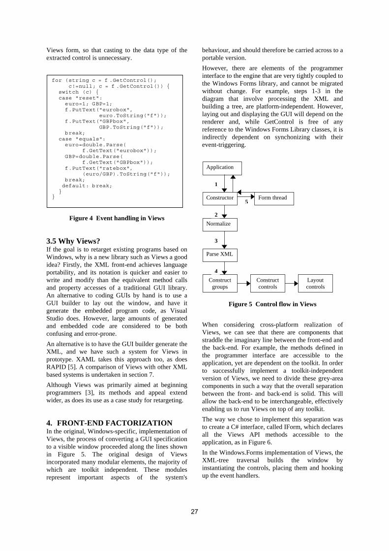
Views form, so that casting to the data type of the extracted control is unnecessary. for (string c = f .GetControl(); c!=null; c = f .GetControl()) { switch (c) { case "reset": euro=1; GBP=1; f.PutText("eurobox", euro.ToString("f")); f.PutText("GBPbox", GBP.ToString("f")); break; case "equals": euro=double.Parse( f.GetText("eurobox")); GBP=double.Parse( f.GetText("GBPbox")); f.PutText("ratebox", (euro/GBP).ToString("f")); break; default: break; } }
Figure 4 Event handling in Views
3.5 Why Views? If the goal is to retarget existing programs based on Windows, why is a new library such as Views a good idea? Firstly, the XML front-end achieves language portability, and its notation is quicker and easier to write and modify than the equivalent method calls and property accesses of a traditional GUI library. An alternative to coding GUIs by hand is to use a GUI builder to lay out the window, and have it generate the embedded program code, as Visual Studio does. However, large amounts of generated and embedded code are considered to be both confusing and error-prone. An alternative is to have the GUI builder generate the XML, and we have such a system for Views in prototype. XAML takes this approach too, as does RAPID [5]. A comparison of Views with other XML based systems is undertaken in section 7. Although Views was primarily aimed at beginning programmers [3], its methods and appeal extend wider, as does its use as a case study for retargeting.
4. FRONT-END FACTORIZATION In the original, Windows-specific, implementation of Views, the process of converting a GUI specification to a visible window proceeded along the lines shown in Figure 5. The original design of Views incorporated many modular elements, the majority of which are toolkit independent. These modules represent important aspects of the system's
behaviour, and should therefore be carried across to a portable version. However, there are elements of the programmer interface to the engine that are very tightly coupled to the Windows Forms library, and cannot be migrated without change. For example, steps 1-3 in the diagram that involve processing the XML and building a tree, are platform-independent. However, laying out and displaying the GUI will depend on the renderer and, while GetControl is free of any reference to the Windows Forms Library classes, it is indirectly dependent on synchonizing with their event-triggering. Application
Constructor
Normalize
Parse XML
Construct groups
Form thread
Construct controls
Layout controls
1
2
3
4
5
Figure 5 Control flow in Views
When considering cross-platform realization of Views, we can see that there are components that straddle the imaginary line between the front-end and the back-end. For example, the methods defined in the programmer interface are accessible to the application, yet are dependent on the toolkit. In order to successfully implement a toolkit-independent version of Views, we need to divide these grey-area components in such a way that the overall separation between the front- and back-end is solid. This will allow the back-end to be interchangeable, effectively enabling us to run Views on top of any toolkit. The way we chose to implement this separation was to create a C# interface, called IForm, which declares all the Views API methods accessible to the application, as in Figure 6. In the Windows.Forms implementation of Views, the XML-tree traversal builds the window by instantiating the controls, placing them and hooking up the event handlers.
27

namespace Views { public interface IForm { void HideForm(); void StartApplication(); String GetControl(); String GetText(String name); String GetText(String name, int index); void PutText(String name, String text); void PutText(String name, int index, String text); void PutImage(String name, String filename); int GetValue(String name); void PutValue(String name, int value); } }
Figure 6 The IForm interface
In the toolkit independent version, we do not rely on the back-end to parse or traverse the XML, so there is a requirement to construct a tree comprising toolkit-agnostic nodes which the back-end can traverse and interpret. The nodes are instances of a new class, Ctrl, which encapsulates information regarding the name, value, attributes and children of a tag in the XML specification. The tree of Ctrl nodes is built by another new class, Parser, which reproduces all the XML-processing code from the original Views.Form class. Iform replaces Form as the class used to construct a GUI window, as in: Views.Iform f =
new QtForm.QtForm(specEn);
An implementation of the IForm interface can use the Ctrl tree to construct control instances specific to the toolkit, without having to be aware of the original XML tree. Thus we have successfully separated the front-end and back-end of Views. The XML has been cleared of all references to toolkit classes, and the programmer interface has been placed behind a clean interface that deals only in names and integer values. A reusable abstraction of the controls and their attributes was created to purge the back-end code of any references to the XML structure.
5. BACK-END IMPLEMENTATION For our test implementation of the retargetable Views framework, we chose Trolltech's Qt toolkit. Qt is a complete application development library for C++, including APIs for GUI rendering, XML parsing, database connectivity and much more. Full details of our implementation are given in [17]. Some of the
issues that relate specifically to .NET with Qt are mentioned here.
5.1 Language interoperability Since Qt is written for, and in, C++, an interoperability layer (written in C#) that implements the interface is required. Thus we have a C# class, QtForm, that implements IForm, but delegates most of its functionality to a wrapper class, QtWrapper. The latter consists of a set of simple wrapper methods that correspond with the methods defined in IForm, and a set of private, static methods that link with externally defined C++ methods. Two additional issues were solved at this point. First, because C# and C++ have different mechanisms for dealing with strings, it was necessary to write marshalling methods that convert between the two. The second aspect is the entry-point specification in the DllImport attribute attached to the GetText method. The C++ linker provides a specially encoded string for every method declared to be externally visible in the source code, called its entry-point. This string can be used by other languages to discover the method within the dll that is produced from the C++ source code. Unfortunately the entry-point is compiler-specific, and also differs from OS to OS. Thus, until a truly platform independent entry-point specification mechanism is found, the QtWrapper class will require adjustment for every platform/compiler combination to which ViewsQt is ported. Returning briefly to the implementation of the IForm interface, QtForm, we can now easily invoke the methods of the C# QtWrapper class, blissfully unaware of the underlying C++ implementation: public String GetText( String name, int index) { return this.wrapper.GetText (name, index); }
5.2 Garbage collection When writing an interoperable program it is vital to ensure that references to elements in one language made in the other are kept valid for the lifetime of that reference. When one of the languages is managed (i.e. has built-in garbage collection), this task adopts an extra degree of complexity – the rearrangement of the heap will invalidate any references that weren't present on the stack during the collector's walk, which includes those held by the other program. In this case, the referenced object is still on the heap, indicating that a reference still exists within the managed program. More serious is the situation where the unmanaged program holds the only references to an object on the managed heap.
28

The garbage collector will happily free the heap space, once again invalidating the unmanaged reference. There are two areas of ViewsQt where careful memory management is necessary to prevent errors. The first is the passing of strings between C# and C++, which happens in the QtWrapper and QtCtrl twins. The second is the pointer to the C++ QtCtrl instance held by the C# QtCtrl instance. In the context of the string-passing, a string passed from C# to C++ must not be garbage collected before the C++ code has had enough time to copy the contents to its own heap. The QtCtrl issue is slightly trickier. In this case, we wish to prevent garbage collection on the C# side so that we can tidy up the C++ heap at the end of the program. In both cases, we stop the C# garbage collector from collecting the objects by obtaining instances of the System.Runtime.InteropServices.GCHandle class for each object. In doing so, the garbage collector treats the objects as if they had been pinned down in the heap – they cannot be moved or removed. We maintain a list of these GCHandle instances so that we can free them at an appropriate point in the execution. We don't mind the GCHandle instances themselves being moved around, as long as the objects they point to stay put.
5.3 Handling Events There are two kinds of event handling which need to occur in an implementation of Views. The first is an internal mechanism that responds to the push-based events received from the GUI controls. A user of Views is shielded from this implementation by the second kind of handler, a pull-based (or polling) mechanism implemented in the GetControl method. These two event handler types are complementary – when the GUI triggers an event, the internal handler looks up the name of the source control and forwards it to the GetControl. The application can then handle the event suitably. Figure 7 illustrates the two kinds of event handling interacting with each other. In (1) the user’s program calls GetControl, which blocks indefinitely. In (2) the operating system’s windowing system interprets a user’s gesture with the mouse or keyboard as an event, and passes it onto the event queue. The toolkit, having registered with the queue to hear about such events, picks up the information, encapsulates it in an Event object and passes it onto views in (3). Views extracts the name of the user-interface control (in this case button X) from the event information and passes it, in (4), to the user’s program as the return value of the GetControl method.
In ViewsQt, we instrument push-based event handling by providing “slot” methods that are invoked when a control's “signal” is emitted. This is not unlike C#'s event implementation, where a multi-cast delegate (slot) is associated with a specific event (signal) published by an object. (In both C# and Qt, any object may fire events.) While it is possible to create a separate method for each kind of signal that each kind of control emits, we felt it a better abstraction to filter the events in such a way that a single eventHappened signal is emitted that contains a reference to the name of the control that originally emitted the event.
User’s program
Views
Toolkit
OS windowing system
1) GetControl
2) publish click event on button X
3) push event
4) GetControl returns “X”
X
Figure 7 Event handling
This brings us to the implementation of the pull-based event handler. When a button is clicked, for example, the clicked method defined in QtWrapper is invoked. This method simply invokes a function pointer, listener, that is defined in the QtWrapper class. This function pointer references a method signature assigned to it in the SetListener method. The constructor for QtForm invokes the SetListener method defined in the C# QtWrapper class, passing it a variable called callback. This variable is in fact a C# delegate that refers to the ClickHappened defined in the QtForm class. The delegate is of type Delegate, which is declared in the C# QtWrapper class. The declaration of Delegate and the instantiation of callback are shown below: public delegate void Callback( [In] IntPtr name); QtWrapper.Callback callback = new QtWrapper.Callback(ClickHappened); The C# QtWrapper class imports the setListener method from its C++ equivalent as follows: static extern void setListener( [In] IntPtr ptr,
29

[In, MarshalAs( UnmanagedType.FunctionPtr)] Callback l);
The MarshalAs annotation specifies that the reference to the Callback passed to setListener should be converted to a native function pointer. This amazingly simple mechanism allows native C++ code to easily invoke methods defined in C#. A proviso is that the method signature in C++ must specify its method-pointer argument using an equivalent descriptor.
5.4 Matching the libraries In retargeting a library via a third party toolkit, it is inevitable that not all features offered in the original will be matched in the other. We were fortunate that there was only one such disparity between Forms and Qt, the DomainUpDown, which displays a single string from a list of strings, with up/down buttons to select other strings in the list. The closest equivalent in Qt is the QSpinBox, which by default displays a single integer in a range, with up/down buttons to select the next/previous value. We found it was possible to achieve a mapping by extending the class and overriding some methods. The code the user writes remains unchanged despite this underlying change, which meets the requirement that retargeting Views should not change the front-end syntax or semantics.
5.5 The Linux port Since Linux has such a huge following, expecially in academia, it was a primary objective to get Views onto this platform. Once Views had been retargeted to Qt, thus eliminating the dependence on Windows.Forms, it could be run on Rotor (and all its platforms) as well as Mono (and its platforms). A group of students undertook the port to Linux, which involved writing the make files and resolving issues of paths and error messages. It was interesting that the port to Debian Linux did not work immediately on other Linux versions, such as Gentoo and Mandrake, and work is progressing on those.
6. EVALUATION 6.1 Example Figure 8 (a) and (b) show a GUI with a variety of controls as rendered by ViewsQt and Views, both running on Windows. The program is taken from Chapter 5 of [3]. The back-end abstraction can be seen to work, at least in the Qt case. That is, constructing an IForm instance that mediates between the Views front-end and objects specific to the back-end GUI toolkit is not difficult, and most of
the retargeting effort lies in implementing the objects. Furthermore, these objects are not especially complex, but it is important to instrument all the functionality expected by the front-end, and to accommodate issues of interoperability between languages. As mentioned above, we tried as far as possible to keep the code that a user of Views would write the same across both implementations. This was not possible in the case of the main application thread, but in such cases a balance must be struck between that which we would rather not to do and that which we cannot do. Adding a single line of thread-related code to the application forms this balance.
6.2 Other platforms and languages Using Rotor as the base CLI, ViewsQt was successfully run on BSD UNIX and MacOS X. It is also worth reiterating that because of the language interoperability of .NET, ViewsQt, although written C# and C++, is available to programmers writing applications in other .NET languages. Specifically, it has been tested with programs written in C++ and Visual Basic. So far, the programs run correctly, and no changes to Views have been required.
6.3 Choice of toolkit A key component of our methodology is the straight use of an existing multi-platform toolkit, rather than any writing or re-tooling. Three commercially available toolkits are Tcl/Tk, Gtk+ and Qt. In the planning phase of the retargeting project, Tcl/TK was considered as a viable option for the implementation. However, we chose to use Qt as Tcl/TK involved not only a significant performance trade-off (Tcl is always interpreted), but also a steeper learning curve in order to become conversant with Tcl's syntax and semantics. Qt, being entirely based on C++ and presenting a very natural programming interface, was the better choice for our purposes. However, one disadvantage to using Qt is that a development license must be purchased for the Windows version (Qt/Windows) in situations not covered by an academic licence or where the 30-day trial period is insufficient. An important factor in choosing a toolkit is that it must be as multi-platform as possible. In this respect, Gtk+ would also have been a possibility. However, the toolkit is completely hidden from the developer, therefore there is nothing to be gained in repeating the exercise with a second toolkit.
30

Figure 8 A program in ViewsQT and Views
7. RELATED WORK In looking at related work, we concentrate on how our methodology relates to other similar attempts to provide cross-platform libraries. Predictably, the major effort in this regard has centred on GUI interfaces and toolkits, thus this section focuses on efforts in this area..
7.1 Declarative UI models A key component of the retargeting strategy is the introduction of XML for the specification of the GUI. Two examples of the genre of declarative user interface models are IUP/LED [12] and CIRL/PIWI [7]. In both cases, a declarative language (LED and CIRL) was provided to describe the user interface in terms of its controls and layout. On the API front, they contain functions for hooking events signaled by the interface to call-back methods defined in the user’s application, and functions to query and alter attributes of the controls displayed. The call-back event model is used so that the usual native windowing toolkit’s events are filtered down to those relevant to the application. Both CIRL/PIWI and IUP/LED were designed from the start to abstract the GUI description from the underlying platform’s toolkit, and to provide a similar look-and-feel across the various platforms. The creators of both projects, however, lament the absence of an existing toolkit that provided a
common look-and-feel across various platforms (both projects were born in the pre-Java and before any widely-accepted platform-independent toolkits, such as Qt and Tcl/TK, were available). Our work on the ViewsQt project was not hindered by these concerns because of the high-quality, platform independent toolkits available to us today.
7.2 XAML and XUL Views belongs to the concrete representation model subdivision of the declarative user interface models, which describes user interfaces in terms of the controls displayed to the user, their composition and their layout. Such declarative user-interface models are not new [8,14], and XML is broadly being adopted as the favourite notation for these languages. Two modern, XML-based models are XUL and XAML. XUL is the model used by the Mozilla family of browsers. A feature of XUL is the ability to create additional custom widgets using a related language called the Extensible Bindings Language (XBL). XUL is certainly cross platform, but its primary disadvantage is that it is tied to JavaScript for the event handlers. XAML is the model Microsoft is making available with Version 2 of the .NET Framework, and is also the foundation for the Avalon windowing system component of the Longhorn version of Windows.
31

XAML is very similar to Views in that rides on the language interoperability of .NET. Unlike Views, there are no push-based event methods, and all handlers are also indicated as method names in the XML. Of course, Microsoft does not intend that anyone would actually write XAML: it is more the output notation from the GUI-builder of Visual Studio. There is nothing intrinsically cross-platform in XAML, since it still relies on System.Windows.Forms for events and rendering. Thus XUL and XAML are variations of the stages represented by Figure 1(a) and (b). The big difference between them and Views is that both XUL and XAML allow (but do not compel) the programmer to embed event-handling code (JavaScript, and any .NET language, respectively) within the user interface declaration. The Views model, on the other hand, provides an engine that intercedes on behalf of the GUI to signal events to the host application. While the functionality offered by XUL and XAML is attractive, we contend that the separation of concerns evinced by Views’ engine-based approach is cleaner and offers greater maintainability and ease-of-use to the programmer and designer.
7.3 Other multiplatform toolkits We have already mention in Section 1 the efforts to extend platform independence beyond GUIs [11, 6] and the ports to Mono of Gtk# and Qt#. It will be interesting to see if the idiom of these toolkits becomes so entrenched with the .NET Linux community, that XAML will not in the end gain wide acceptance.
8. CONCLUSION AND FUTURE WORK ViewsQt is a conversion of an XML-based GUI library to support a retargetable back-end. The project involved extracting the common front-end elements of XML checking, parsing, and abstract control creation from the original Views engine, and replacing references to the Windows Forms library classes with calls to a C# interface. This interface hides the toolkit-specific back-end components behind a small (and easy to learn) set of methods. Finally, we created an implementation of this interface for the Qt windowing toolkit, and provided a set of classes to delegate calls from the C# objects to their counterpart C++ objects. Experiments have shown that the ViewsQt code is portable, with only a few changes to the C++ classes (related to interface inclusion and entry-point specification) required to compile and execute the code on the Linux and Mac OS X operating systems.
On the Windows platform, ViewsQt works well with both the .NET Framework and Rotor. Future work on ViewsQt will entail smoothing out a few wrinkles with regards to the colour and font properties of the controls, and perhaps adding support for more controls that the Views specification does not cater for (e.g. menus, status- and tool-bars). Possibly, an implementation using a second toolkit such as GTK+ will be undertaken to prove the actual retargetability of the front-end. It is also our intention to exercise the methodology here on libraries other than simple GUIs. Examples would be speech synthesis, or the tangible user interfaces, which are attracting attention. At the time of writing, an exciting development is the complete rewriting of Views in .NET 2, based entirely on reflection. The prototype system is operational, and is about one-sixth the length of the original because actual controls are picked up directly by name from the XML specification, rather than going through a program transformation. We will be investigating whether the same leverage can be obtained for Qt, and hence for any third part toolkit.
ACKNOWLEDGEMENTS This work was supported by Microsoft Research and THRIP Grant no. 2788. We would like to thank David-John Miller for his enthusiastic assistance with the project, and acknowledge the inspiration of Nigel Horspool of the University of Victoria, who wrote Views. Johannes Eickhold, Mathhias Kempka and Mihael Vrbanec of TU Karlsruhe were responsible for the port of ViewsQt to Linux.
REFERENCES [1] Niel M Bernstein, Using the Gtk toolkit with
Mono, O’Reilly ONDotNet, online article 2004/08/9/ August 2004.
[2] Judith Bishop and Nigel Horspool. C# Concisely. Addison Wesley, 2004.
[3] Judith Bishop and Nigel Horspool. Developing principles of GUI programming using Views. Proc. ACM-SIGCSE, 373-377, March 2004.
[4] Judith Bishop, R. Nigel Horspool, and Basil Worrall. Experience with integrating Java with C# and .NET. Concurrency and Computation: Practice and Experience. To appear, June 2005.
[5] Martin C. Carlisle and P. Maes. RAPID: A Free, Portable GUI Designer for Ada, SIGAda '98, 158-164, ACM, 1998.
32

[6] Martin C Carlisle, A truly implementation independent GUI development tool, Proc. SIGAda ‘99, 47 - 52 , ACM, 1999
[7] D.D. Cowan et al. CIRL/PIWI: A GUI toolkit supporting retargetability. Software—Practice and Experience, 23(5):511–527, 1993.
[8] Paulo Pinheiro da Silva. User interface declarative models and development environments: a survey. Proc. DSV-IS2000, LNCS 1946, 207–226, Springer-Verlag 2000.
[9] ECMA Standard 335: Common language infrastructure (CLI), December 2002.
[10] Andrew Kennedy and Don Syme. Design and implementation of generics for the .NET common language runtime, Proc. ACM SIGPLAN PLDI, 1-12, June 2001.
[11] Scott R. Klemmer et al, Papier-Mâché: toolkit support for tangible input. CHI 2004: Proc. ACM Conf. on Human Factors in Computing Systems, CHI Letters, 6, 399–406, 2004.
[12] Wei-Meng Lee, Writing Cross-Platform Mobile Applications Using Crossfire, O’Reilly ONDotNet, online article 2004/07/12, 2004
[13] C.H. Levy et al. IUP/LED: A portable user interface development Tool. Software—Practice and Experience, 26 (7):737–762, 1996.
[14] C. Lüth, B. Wolff, TAS — A generic window inference system, 13th Conf on Theorem proving and higher order logics, in LNCS 1869, 405-422, Springer-Verlag 2000.
[15] Egbert Schlungbaum. Individual User Interfaces and Model-Based User Interface Software Tools.
Proc. ACM Intelligent User Interfaces IUI’97, 229–232, Orlando, Florida, USA, January, 1997
[16] Meurig Sage, FranTk – a declarative GUI language for Haskell, Proc. 5th ACM SIGPLAN conf. on Functional Programming, 106–117, 2000.
[17] Basil Worrall, Building a retargetable XML GUI toolkit, Polelo technical report #6–2004.
WEB REFERENCES (checked 14/2/2005) Avalon msdn.microsoft.com/longhorn/
understanding/pillars/avalon/ CLI www.ecma-international.org Debian www.debian.org Gtk# gtk-sharp.sourceforge.net Gtk+ www.gtk.org Gyro research.microsoft.com/projects/clrgen/ Longhorn longhorn.msdn.microsoft.com Mono www.go-mono.com Qt www.trolltech.com Qt# qtcsharp.sourgeforge.net Tcl/Tk www.tcl.tk Rotor msdn.microsoft.com/net/sscli/ Views views.cs.up.ac.za ViewsQt sourceforge.net/projects/viewsqt/ XAML link from Avalon page XUL www.mozilla.org/projects/xul
33

34

Using Web Services on Mobile Devices to
Transparently Access .NET Remoting Objects
Bert Vanhooff K.U. Leuven
Celestijnenlaan 200A B, 3001, Leuven
bert.vanhooff
@cs.kuleuven.ac.be
Davy Preuveneers K.U. Leuven
Celestijnenlaan 200A B, 3001, Leuven
davy.preuveneers
@cs.kuleuven.ac.be
Yolande Berbers K.U. Leuven
Celestijnenlaan 200A B, 3001, Leuven
yolande.berbers
@cs.kuleuven.ac.be
ABSTRACT
With the growing popularity of powerful connected mobile devices (PDAs, smart phones, etc.), an opportunity to
extend existing distributed applications with mobile clients emerges. The Microsoft .NET Compact Framework
offers a development platform for mobile applications but is lacking support for .NET Remoting, which is the
.NET middleware infrastructure for inter-application communication. The current version of the .NET Compact
Framework (1.0, SP2) does support communication using web services. Unfortunately this support cannot be
used to seamlessly integrate with an existing .NET Remoting application. In this paper, we propose an approach
that leverages the present support for web services to make such integration possible. Our solution dynamically
maps back and forth between .NET Remoting and web service messages. An implementation of this solution
resulted in a set of tools and components that can readily be used to start developing mobile clients that interop-
erate with existing .NET Remoting applications.
Keywords
.NET Remoting, Web Services, .NET Compact Framework, Interoperability, Mobility
1. INTRODUCTION .NET is a Microsoft brand name that encompasses a
whole array of technologies. A few key terms associ-
ated with this brand name are connected systems,
smart devices and web centric computing. These
terms could be categorized under the more general
denominator of distributed systems. In short, .NET
offers a complete package of tools and technologies
for developing applications, especially targeted to-
wards distributed systems.
The most important part of .NET is the .NET Frame-
work [Mic]. It consists of an execution environment
for applications and a comprehensive class library.
To support the development of distributed applica-
tions, .NET Remoting [Mcl03] was included. This is
an extensible middleware infrastructure intended to
simplify the development of distributed systems. It is
comparable to Java RMI [Sun].
The .NET Compact Framework [Wig03] is a
slimmed down version of the .NET Framework made
to run on embedded devices like PDAs or smart
phones. To take into account the resource limitations
of these devices, a dedicated execution environment
was crafted and some classes and methods of the
standard .NET class library were removed. The en-
tire namespace of the Remoting classes was removed.
As a consequence, the only high-level communication
facility present in the .NET Compact Framework is
provided in the form of a number of classes to sup-
port the invocation of web services.
Web services can be interpreted in a broad sense as
all means by which a service can be offered by one
application and used by another by leveraging Inter-
net technologies. When we refer to web services
[W3c02], [Boo03], we specifically refer to SOAP
(Simple Object Access Protocol) [Box00] over HTTP
and WSDL (Web Service Description Language)
[W3c03]. SOAP is the XML based protocol of the
messages sent by a web service, while WSDL is the
Permission to make digital or hard copies of all or part of
this work for personal or classroom use is granted without
fee provided that copies are not made or distributed for
profit or commercial advantage and that copies bear this
notice and the full citation on the first page. To copy oth-
erwise, or republish, to post on servers or to redistribute to
lists, requires prior specific permission and/or a fee.
.NET Technologies’2005 conference proceedings,
ISBN 7/,75832,/0,0Copyright UNION Agency – Science Press, Plzen, Czech Republic
35
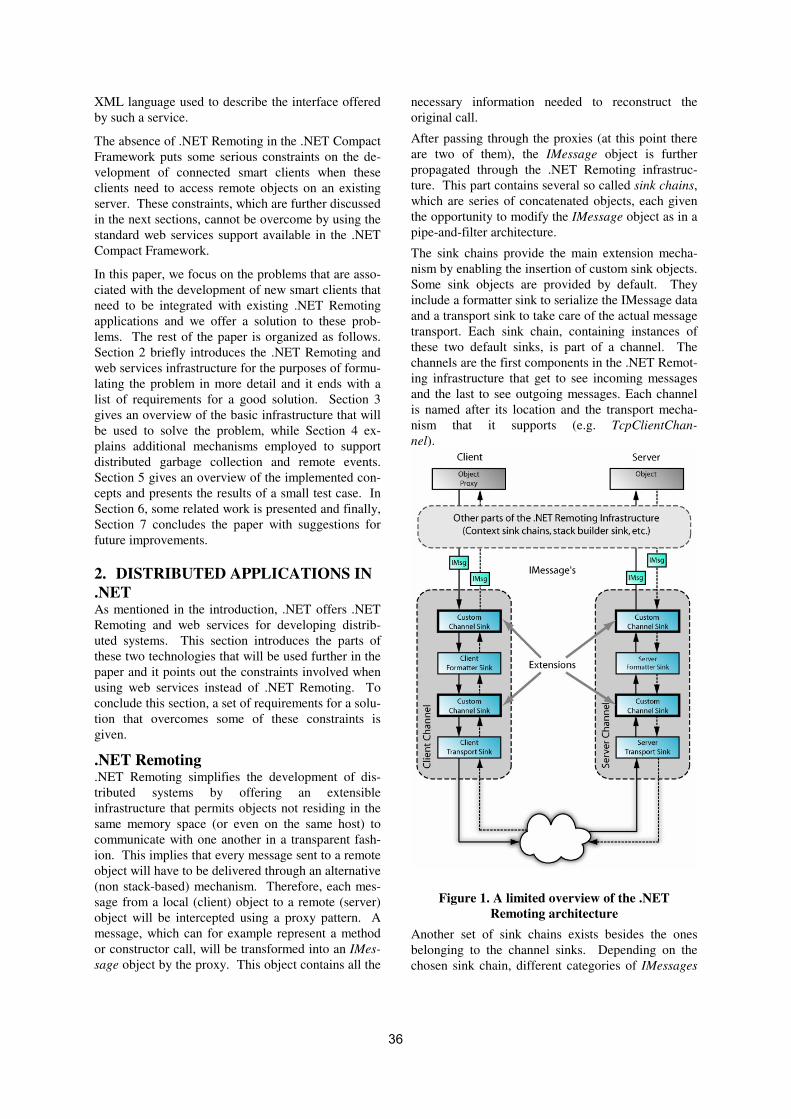
XML language used to describe the interface offered
by such a service.
The absence of .NET Remoting in the .NET Compact
Framework puts some serious constraints on the de-
velopment of connected smart clients when these
clients need to access remote objects on an existing
server. These constraints, which are further discussed
in the next sections, cannot be overcome by using the
standard web services support available in the .NET
Compact Framework.
In this paper, we focus on the problems that are asso-
ciated with the development of new smart clients that
need to be integrated with existing .NET Remoting
applications and we offer a solution to these prob-
lems. The rest of the paper is organized as follows.
Section 2 briefly introduces the .NET Remoting and
web services infrastructure for the purposes of formu-
lating the problem in more detail and it ends with a
list of requirements for a good solution. Section 3
gives an overview of the basic infrastructure that will
be used to solve the problem, while Section 4 ex-
plains additional mechanisms employed to support
distributed garbage collection and remote events.
Section 5 gives an overview of the implemented con-
cepts and presents the results of a small test case. In
Section 6, some related work is presented and finally,
Section 7 concludes the paper with suggestions for
future improvements.
2. DISTRIBUTED APPLICATIONS IN
.NET As mentioned in the introduction, .NET offers .NET
Remoting and web services for developing distrib-
uted systems. This section introduces the parts of
these two technologies that will be used further in the
paper and it points out the constraints involved when
using web services instead of .NET Remoting. To
conclude this section, a set of requirements for a solu-
tion that overcomes some of these constraints is
given.
.NET Remoting
.NET Remoting simplifies the development of dis-
tributed systems by offering an extensible
infrastructure that permits objects not residing in the
same memory space (or even on the same host) to
communicate with one another in a transparent fash-
ion. This implies that every message sent to a remote
object will have to be delivered through an alternative
(non stack-based) mechanism. Therefore, each mes-
sage from a local (client) object to a remote (server)
object will be intercepted using a proxy pattern. A
message, which can for example represent a method
or constructor call, will be transformed into an IMes-
sage object by the proxy. This object contains all the
necessary information needed to reconstruct the
original call.
After passing through the proxies (at this point there
are two of them), the IMessage object is further
propagated through the .NET Remoting infrastruc-
ture. This part contains several so called sink chains,
which are series of concatenated objects, each given
the opportunity to modify the IMessage object as in a
pipe-and-filter architecture.
The sink chains provide the main extension mecha-
nism by enabling the insertion of custom sink objects.
Some sink objects are provided by default. They
include a formatter sink to serialize the IMessage data
and a transport sink to take care of the actual message
transport. Each sink chain, containing instances of
these two default sinks, is part of a channel. The
channels are the first components in the .NET Remot-
ing infrastructure that get to see incoming messages
and the last to see outgoing messages. Each channel
is named after its location and the transport mecha-
nism that it supports (e.g. TcpClientChan-
nel).
Figure 1. A limited overview of the .NET
Remoting architecture
Another set of sink chains exists besides the ones
belonging to the channel sinks. Depending on the
chosen sink chain, different categories of IMessages
36

will be intercepted. By choosing the server object
sink chain, only IMessages originating from a speci-
fied object will be seen. On the other hand one can
choose a channel sink chain (discussed in the para-
graph above) to intercept every message from every
object that uses that channel.
The extension mechanism, using custom sink objects,
can be used to add, for example, encryption or log-
ging facilities to the standard .NET Remoting
functionality. A more exotic extension could be one
that provides a new serialization mechanism.
A high-level overview of a limited part of the .NET
Remoting architecture can be found in Figure 1. It
shows the possible flow of an IMessage through the
sinks in a channel, when both client and server are
using .NET Remoting. An IMessage is created in the
proxy on the client and travels through the infrastruc-
ture (full lines) until it arrives at the first Custom
Channel Sink, which is a specialized version of a
message sink. Each custom sink shown in the figure
actually represents either one custom message sink or
a chain of custom message sinks (only one is shown
to save space). The message then moves further to
the Client Formatter Sink, where it is serialized. Af-
ter that, another series of Custom Channel Sinks and,
at last, the Client Transport Sink are passed. This last
sink physically sends the message to the server using
some kind of network technology. When the message
is received at the server, an equivalent chain of sinks
is passed on the server until the call to the actual ob-
ject can be executed. A response will, in turn, be
represented by an IMessage that travels in the oppo-
site direction (dotted lines).
.NET Remoting also offers solutions for considera-
tions such as object lifetime management and object
activation, but these will not be discussed here.
Web services One of the advantages of using .NET Remoting, be-
sides its extensibility with message sinks, is its direct
support for offering web services through its infra-
structure. Remote objects can be accessed – in a
limited way – using web services, meaning that all
.NET Remoting extension mechanisms can be used
while handling a web service request. This means
that the whole client side in Figure 1 could be re-
placed by a web service client. However, some
functionality, as it is available when using a .NET
Remoting client, will be lost due to the inherent limi-
tations of standard web services [Alm01].
The main limitation in this case is that they have a
procedure oriented architecture instead of an object-
oriented architecture. The full fidelity of an object
graph at a server cannot be seen by a web service
client because object references cannot be passed.
When accessing a remote object through a web ser-
vice in .NET Remoting, the caller can only call
methods that return primitive or structured data-types.
As a consequence, he cannot get out of the scope of
the initial object because any call to a method, which
would normally return a reference to an associated
object, will only return the data contained in the asso-
ciated object and not the object reference itself.
In summary, when web services are used to access
remote objects, the objects need to be published on
well-known URLs in advance and they may not be
removed during the application’s lifetime. Other
objects that are created during the operation of the
system will not be accessible. Consequently, an ap-
plication offered as a set of web services has to have
a static object graph, at least for the objects published
as web services. More specifically an object that is
published as a web service should not be deleted as
this would result in, unanticipated, access faults. In
addition newly created objects cannot be directly
accessed by web service clients. Mind that data pre-
sent in newly created objects can be accessed
indirectly through methods from another object that is
published as a web service.
A web service is generally accessed using a proxy in
order to provide for some transparency and to keep
the programmer from having to do al lot of cumber-
some coding. There are standard tools available to
generate these proxies for a remote object. Whenever
the tools encounter a method that returns or accepts
an object, this object will be mapped to a complex
SOAP data structure. Consequently, for these prox-
ies the very notion of an object disappears.
An additional restriction is the inability to let the
server initiate communications, for example in the
case of notifying the client of an event occurrence.
Client and server are not peers as is the case with
.NET Remoting.
These limitations, along with the dynamic nature of
most object graphs, make the web service support for
.NET Remoting inadequate for developing smart cli-
ents with the same capabilities as full .NET Remoting
clients. This becomes even more important when
extending an existing .NET Remoting application that
was not originally designed for extension to web ser-
vices. The focus of this paper is on extending such
applications.
In the next subsection, we state the requirements that
need to be fulfilled by a useful solution.
Requirements Suppose a server running .NET Remoting is exposing
some of its objects for remote access. All .NET Re-
moting clients can access these objects as if they were
local to them. If one wants to port such a client to
37

run on a smart device, major problems will occur
because, apart from web services (with their already
discussed shortcomings), the .NET Compact Frame-
work lacks support for accessing these remote
objects. Therefore we have to figure out an alterna-
tive approach for interacting with remote objects that
offers most of the .NET Remoting capabilities. A
concrete list of the requirements we expect a good
solution to meet is given here:
1. make the object graph on the server navigable
from the client;
2. enable the client to refer to a specific object on
the server;
3. enable method calls on remote objects (with ob-
ject references both as parameters and as return
type);
4. make interactions as transparent as possible and
hide communication details;
5. enable callbacks from the server;
6. enable fast development of new clients;
7. minimize the impact on existing applications.
These requirements need to be fulfilled by reusing
large parts of the already available infrastructure on
both the client and the server platform. The client
implementation must take into account the typical
limitations of embedded devices (small memory size,
limited processing power, etc.). This last requirement
makes the porting of the whole .NET Remoting infra-
structure to the .NET Compact Framework an
unrealistic option.
3. USING WEB SERVICES TO
ACCESS REMOTE OBJECTS In this section we explain the approach we take to
making remote objects available to clients who run
the .NET Compact Framework. Requirements 1, 2, 3
and 4 will be addressed here. Requirement 5 will be
discussed in Section 4 while requirements 6 and 7
will be addressed throughout all the next sections and
especially in Section 5.
In the current section we will explain how URLs can
be used as object references and web services to en-
able basic communication.
Basic approach As mentioned before, .NET Remoting can publish a
degenerated version of the public interface of a re-
mote object through a web service on a well-known
URL. We will use this capability and modify the way
of using web services to overcome their inherent limi-
tations. The envisioned idea in this paper is to make
the publication of a remote object as a web service
happen dynamically whenever a client requests an
operation which returns a remote object. Further-
more, to enable navigation to another object, the
URL that uniquely identifies that remote object will
be passed in SOAP messages. This will in fact indi-
cate the web service of that object though it can be
mapped one-to-one onto the actual object, effectively
replacing the real object reference. The idea is visu-
ally represented in Figure 2.
The figure presents a graph of three interconnected
objects, objA, objB and objC. The starting object
objA will be accessible using a web service on a well-
known URL (1). By invoking methods on this object,
one can navigate to the other objects in the graph as
follows. Whenever the client calls a method that
should return a reference to another object (which
cannot be transported using standard web services),
this object will be exposed through a web service.
The URL to reach this service will instead be re-
turned to the client as a substitute for the real object
reference. Using this URL, the client can access the
Figure 2. Dynamically exposing objects as web services.
38

new object (2). In this way every object in the graph
can be reached (3), effectively enabling navigability.
To keep object access as transparent as possible to
the client, each remote object will be represented by a
proxy object to hide communication details. In this
way the client thinks it is working with local objects,
which basically is what .NET Remoting is also ac-
complishing.
This approach will require adjustments on both the
client (proxies) and the server (.NET Remoting ex-
tensions). In the next section, we present an
elaboration of the general idea by using a method call
scenario.
Remote method calls To make invocations (made by the caller on the cli-
ent) transparent, two proxies will collaborate to
represent a remote object on the client. The first
proxy, from here on called the transparent proxy will
mimic the interface of the remote object. The second
proxy referred to as the real proxy, will hide commu-
nication details. The names chosen for these proxies
were inspired by the names of the proxies in .NET
Remoting. In this subsection we refer only to the real
proxy. These two proxies reside on the client. The
server side will also need an extension to be able to
handle the client’s requests. This extension will be a
custom message sink object, inserted on top in the
server channel sink.
The real proxy can be partially generated by extract-
ing the interface of its corresponding class. However,
some modifications to this interface are necessary
when generating the proxy. These have to do with
the limitations of web services concerning the trans-
portation of object references. As mentioned in
Section 1, web services cannot transport objects (or
better: references to objects). Only simple and struc-
tured value types can be transported directly. Each
time a non-transportable type is encountered in a
method signature (the return type or a parameter
type), it will be mapped to the transportable string
type. At runtime, this string will contain an object
reference represented by a web service URL (see
Figure 4). An example of the different possibilities is
given in Table 1.
real method signature mapped method signature
int Sqrt(int a) int Sqrt(int a)
Car GetCar(int id) String GetCar(int id)
Car Clone(Car c) String Clone(String c)
Table 1. Mapping an object's interface
We use three different methods to marshal different
types. Objects that are normally marshaled by refer-
ence by the Remoting infrastructure are marshaled by
reference using the URL representation as presented
in Figure 4. Primitive types are marshaled by value
and can be transported directly using SOAP mes-
sages. Complex value types (structs without methods
in C# [Alb01]) can also be transported directly. The
last case occurs when a complex value type contains
extra methods (also structs). We chose to make a
local copy of the instance on the server and then mar-
shal it by reference. Another (maybe better) way to
achieve a correct transport of these complex types is
to transport only the data in the instance using mar-
shal by value. The data can than be loaded into a
corresponding type instance on the client that would
act as a virtual proxy. It does not communicate with
the server but does represent a server type. The latter
solution would be more complicated to implement,
while the first method can use the existing marshal by
reference facility.
If a method does not contain non-transportable types,
it can be offered in the interface unmapped and in-
voked without special intervention. On the other
hand, if a method contains mapped parameters or
return types, then the default mechanisms cannot be
used and the invocation needs special care both on
Figure 3. Invoking a method.
http://145.34.67.10:1200/[type:MyClassLib.MyClass][853b9985]
server location object type unique object
reference
Figure 4 Our web service URL format
39

the client (handled in its proxies) and on the server
(using a sink object).
A case where the return type is mapped will be dis-
cussed here. Suppose one wants to invoke the
method MyClass GetMyClass() on a remote
object that we can reach via a known URL. Through
the mapping mechanism this method will be exposed
as String GetMyClass(), and will be available
as such in the proxy on the client. The sequence of
steps that will take place when calling that method is
shown in Figure 3.
When calling the method, all the details of that call
are serialized into a SOAP message and this message
is sent to the known URL (1). The method is actually
called on a web service proxy that uses the standard
class library of the .NET Compact Framework to hide
the communication details from the caller. The
SOAP message then arrives at the server and is ac-
cepted by the .NET Remoting infrastructure, where it
is automatically deserialized into an IMessage object
containing the same information. After that, it is in-
serted into the right sink chains. This also means that
our custom sink object will get a chance to process
the IMessage. In this case, the sink can just pass the
IMessage further up the chain so that the call can
eventually be invoked (2). On the other hand, if the
method contains mapped parameters, its arguments
will contain URLs that indicate other objects. These
URLs should first be replaced by the actual object
references (which are known on the server) before the
IMessage is further propagated. The result of the
method call will also be intercepted by our message
sink (3). In response it will expose the returned ob-
ject as a web service and replace the object reference
with the URL of the created web service. Also, an
extra reference to this object must be stored on the
server to prevent it from being garbage collected (see
Section 4). Whenever the returned object is a (non-
primitive) value type (struct in C#), a local copy is
stored to preserve the right semantics (see earlier in
this section).
The modified IMessage is now handed over to the
next sink object to eventually be serialized to a SOAP
message and sent back to the client (4). When the
SOAP message is received, it is deserialized. The
returned URL is then given to the proxy, which will
give it back to the caller — which will in practice be
the transparent proxy (see next subsection). The
caller can in turn start invoking methods on the re-
turned ‘object’ represented by the new web service.
This will happen by instantiating a new proxy for the
corresponding type, and initializing it with the given
URL.
The mechanism described above implies that proxies
are available a priori for each type used. This does
not introduce any limitation in our case. Proxy gen-
eration at design time will actually boost performance
by taking away the processing cost of generating
proxies at run time. While it does enable basic com-
munications, the use of the real proxy directly does
not provide for much transparency. The caller does
not see the real method signatures and has to manipu-
late URLs instead of real object references. In the
next subsection, the transparent proxy is added to
solve this problem.
Providing a transparent client interface To make the approach described above more trans-
parent to the caller on the client, an extra level of
indirection is introduced by adding a transparent
proxy that interacts with the real proxy. The interface
of the transparent proxy will mimic the object on the
Figure 5. Using two proxies on the client to provide maximum transparency.
40

server that it represents, effectively providing trans-
parency. Whenever a method invoked on a
transparent proxy contains instances of other trans-
parent proxies in its arguments, the transparent proxy
will translate these arguments into their correspond-
ing URLs and forward the call to the real proxy. The
reverse translation is done with returned values. The
real proxy in turn hides the rest of the communication
details as discussed in the beginning of this section.
Figure 5 shows a general model of the structure.
The scenario presented in Figure 5 starts when the
transparent proxy objA* (indicating that it mimics the
interface of the remote object A) receives a response
from the real proxy after calling its GetObjectB()
method. This is where the scenario presented in
Figure 3 ended by returning an URL to the caller,
which is represented by objA* in the current scenario.
The returned value is the URL to the web service of
object B. The rest of the scenario goes as follows:
1. Upon receiving a URL, the transparent proxy
needs to create the necessary proxy objects that will
enable the client to transparently work with the new
object’s web service. It therefore sends a cre-
ate() message to the objectActivator.
2. This objectActivator will check its cache to
see if it already contains a transparent proxy that re-
fers to the given URL. If none is found, it will create
a new one and add it to the cache.
3. A real proxy to directly interact with the web ser-
vice will also be created.
4. Eventually the newly created transparent proxy
objB* is given back to objA*, whichever object
invoked its method caller.
4. EXTENSIONS FOR LIFETIME
MANAGEMENT AND EVENTS The previous section explained how references to
remote objects can be obtained and how method calls
can be carried out in a transparent fashion. However,
there should also be a mechanism to manage the life-
time of remote objects that are accessed in this way.
The server needs to know which objects are still ref-
erenced in order to carry out meaningful garbage
collection. Requirement 5 also states that events on
the server should be capable of being propagated to
the clients. The mechanisms for addressing these two
issues are presented in this section.
Distributed lifetime management Distributed garbage collection is all about keeping
track of remote references to an object and letting
them play a role in the life cycle of the object. The
goal is to prevent remote objects either from living
forever or from being deleted when they are still in
use. Without further precautions being taken, the
first case would apply to the approach explained so
far. Whenever a client gets a reference to an object
on the server, the object’s local life cycle (the life
cycle of its proxy on the client) will not be known to
the server, which will result in an object that lives
eternally. Note that we will not address the inverse
problem of managing the life cycle of objects on the
client that are referenced by the server because until
now this has not been capable of happening. This
client/server approach rules out the problem of deal-
ing with circular references, which can only occur if
an object acts as both client and server.
A method for solving this problem of having remote
objects that live eternally is to just let the garbage
collector on the client do its work on the proxies and,
whenever a transparent proxy is destructed, to notify
the server of this event. This technique will work
well in our specific case. A survey of more elaborate
techniques for distributed garbage collection is given
in [Pla95]. [Vei03] presents a distributed garbage
collector that improves the current mechanisms used
in .NET. The garbage collector is implemented in
Rotor [Mic2] using the sink based extension mecha-
nism. Our basic approach is illustrated in Figure 6.
1. A transparent proxy on the client is not referenced
anymore and is destroyed by the local garbage collec-
tor.
2. This results in the invocation of the destructor of
that proxy. The transparent proxy will react to this by
invoking the EndLife() method on a special gar-
bage collector proxy (GCProxy), giving its URL as
argument.
Figure 6. Simple distributed garbage collection.
41
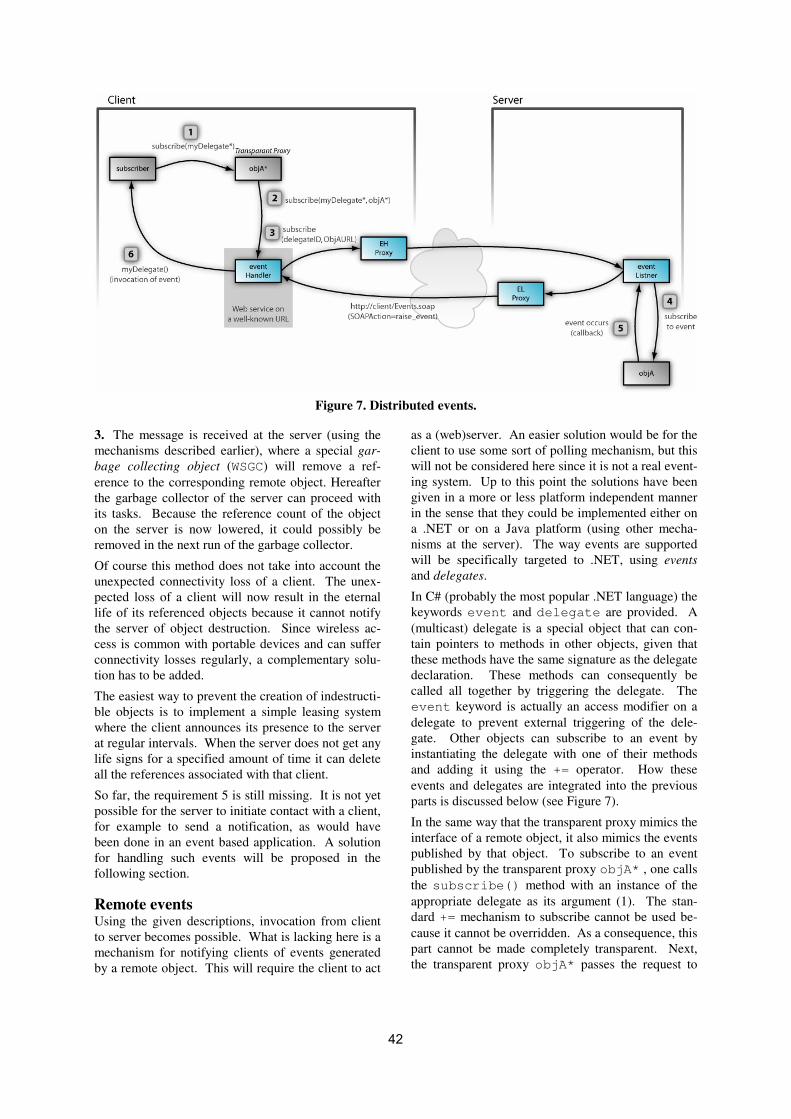
3. The message is received at the server (using the
mechanisms described earlier), where a special gar-
bage collecting object (WSGC) will remove a ref-
erence to the corresponding remote object. Hereafter
the garbage collector of the server can proceed with
its tasks. Because the reference count of the object
on the server is now lowered, it could possibly be
removed in the next run of the garbage collector.
Of course this method does not take into account the
unexpected connectivity loss of a client. The unex-
pected loss of a client will now result in the eternal
life of its referenced objects because it cannot notify
the server of object destruction. Since wireless ac-
cess is common with portable devices and can suffer
connectivity losses regularly, a complementary solu-
tion has to be added.
The easiest way to prevent the creation of indestructi-
ble objects is to implement a simple leasing system
where the client announces its presence to the server
at regular intervals. When the server does not get any
life signs for a specified amount of time it can delete
all the references associated with that client.
So far, the requirement 5 is still missing. It is not yet
possible for the server to initiate contact with a client,
for example to send a notification, as would have
been done in an event based application. A solution
for handling such events will be proposed in the
following section.
Remote events Using the given descriptions, invocation from client
to server becomes possible. What is lacking here is a
mechanism for notifying clients of events generated
by a remote object. This will require the client to act
as a (web)server. An easier solution would be for the
client to use some sort of polling mechanism, but this
will not be considered here since it is not a real event-
ing system. Up to this point the solutions have been
given in a more or less platform independent manner
in the sense that they could be implemented either on
a .NET or on a Java platform (using other mecha-
nisms at the server). The way events are supported
will be specifically targeted to .NET, using events
and delegates.
In C# (probably the most popular .NET language) the
keywords event and delegate are provided. A
(multicast) delegate is a special object that can con-
tain pointers to methods in other objects, given that
these methods have the same signature as the delegate
declaration. These methods can consequently be
called all together by triggering the delegate. The
event keyword is actually an access modifier on a
delegate to prevent external triggering of the dele-
gate. Other objects can subscribe to an event by
instantiating the delegate with one of their methods
and adding it using the += operator. How these
events and delegates are integrated into the previous
parts is discussed below (see Figure 7).
In the same way that the transparent proxy mimics the
interface of a remote object, it also mimics the events
published by that object. To subscribe to an event
published by the transparent proxy objA* , one calls
the subscribe() method with an instance of the
appropriate delegate as its argument (1). The stan-
dard += mechanism to subscribe cannot be used be-
cause it cannot be overridden. As a consequence, this
part cannot be made completely transparent. Next,
the transparent proxy objA* passes the request to
Figure 7. Distributed events.
42

the client’s eventHandler object (2). The even-
tHandler is a transparent proxy that does the
necessary translations of object references to URLs.
The request is then passed to the real proxy (3) be-
longing to the eventHandler object, which sends
the message to the server. A delegate is identified by
an ID number in this stage, so the server can find the
right delegate. When the message arrives at the
server, the custom sink object (not shown in Figure 7)
routes the request to the eventListener object,
which subscribes itself to the event in place of the
transparent proxy (4). When the event occurs (5), the
eventListener is notified. The eventLis-
tener then calls its proxy to translate the event
arguments and send them to the eventHandler on
the client. This is accomplished by running a simple
web server [Pra03] on the client and publishing the
eventHandler’s interface on a well-known URL.
The eventHandler can, if necessary, call the cor-
responding delegate on the client to raise the event
locally (6). Thus it will seem that the event has oc-
curred locally.
5. IMPLEMENTATION OF THE
MODULES TO SUPPORT THE PRO-
POSED CONCEPTS An implementation of the basic ideas was carried out
to prove the feasibility of the proposed concepts. The
results of the implementation can roughly be divided
into two parts: a C# code generator for the client side
proxies and an extension for the .NET Remoting in-
frastructure in the form of a sink object and
supporting objects.
The code generator was implemented in two steps.
First a WSDL generator was developed. It takes one
or more existing classes (residing in compiled assem-
blies) as input and generates corresponding WSDL
files as output. It also takes care of the mapping of
non-transportable types. Next, this WSDL is auto-
matically transformed into real proxies using standard
provided classes in the .NET Framework class li-
brary. In a second phase a code generator for the
transparent proxies was implemented. This was ac-
complished using the excellent support for dynamic
code generation and compilation of the .NET class
library.
All the functionality mentioned was then integrated
into one tool which enables one-click generation of
all the needed proxies. The functionality needed by
all proxies was split off into a separate common li-
brary module that has to be included with each client.
The generator tool can be set to output a compiled
assembly of proxies, ready to be used. By importing
this assembly into a project (in Visual Studio.NET),
the programmer gets a view of all the classes as he
would expect them on the server, thus fulfilling re-
quirements 6 and 7.
Splitting the code generation into a few steps facili-
tates the adaption of the application to generate code
for other (non-.NET) programming languages. Espe-
cially the generation of the intermediate WSDL files
opens up the possibility of using existing tools to
generate real proxies in other languages without hav-
ing to re-code the entire logic.
Extending the .NET Remoting behavior did not prove
to be as easy as expected. There turned out to be
many more subtleties in choosing the right extension
mechanism than one would expect. The .NET Re-
moting introduction in this paper only touches on the
many extension possibilities. A suitable extension
mechanism was finally found: a custom channel sink
inserted above the predefined server formatter sink.
This component is responsible for mapping the run-
time arguments and return values back and forth to
URLs. It therefore shares some functionality with the
WSDL generator.
Our channel sink undertakes four steps in intercepting
messages:
1. Check the input message. Only accept IMethod-
Messages. We do not treat constructor messages for
example.
2. Adapt the incoming message:
•••• Search for references in the parameter list.
•••• Skip simple messages (containing only primi-
tive types).
•••• Convert the references into real object refer-
ences by searching the server’s hash table.
Create a new writable IMessage, copy the data
from the original message and replace the refer-
ences.
3. Forward the newly created message to the next
sink in the chain.
4. Adapt the return message:
•••• If the return type is primitive, the instance is
marshaled by value and directly send back.
•••• If the return type has to be marshaled by refer-
ence, a unique ID is generated to be able to
construct a valid URL. Next, the instance is
published as a web service on this URL and the
mapping between URL and real object refer-
ence is saved in a hash map, which also places
an extra reference to the object on the server for
use in the distributed garbage collection. Fi-
nally the return message is changed with the
marshaled return value.
•••• In case of a complex value type with methods, a
local copy of the instance is first created and
43
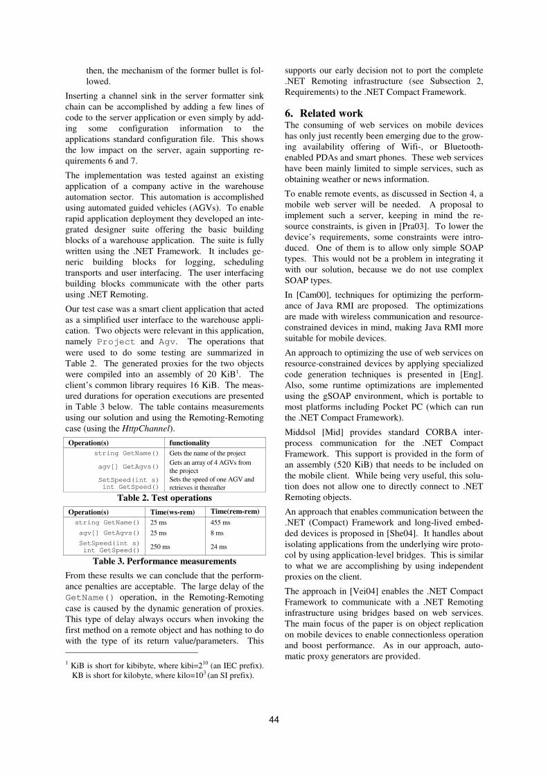
then, the mechanism of the former bullet is fol-
lowed.
Inserting a channel sink in the server formatter sink
chain can be accomplished by adding a few lines of
code to the server application or even simply by add-
ing some configuration information to the
applications standard configuration file. This shows
the low impact on the server, again supporting re-
quirements 6 and 7.
The implementation was tested against an existing
application of a company active in the warehouse
automation sector. This automation is accomplished
using automated guided vehicles (AGVs). To enable
rapid application deployment they developed an inte-
grated designer suite offering the basic building
blocks of a warehouse application. The suite is fully
written using the .NET Framework. It includes ge-
neric building blocks for logging, scheduling
transports and user interfacing. The user interfacing
building blocks communicate with the other parts
using .NET Remoting.
Our test case was a smart client application that acted
as a simplified user interface to the warehouse appli-
cation. Two objects were relevant in this application,
namely Project and Agv. The operations that
were used to do some testing are summarized in
Table 2. The generated proxies for the two objects
were compiled into an assembly of 20 KiB1. The
client’s common library requires 16 KiB. The meas-
ured durations for operation executions are presented
in Table 3 below. The table contains measurements
using our solution and using the Remoting-Remoting
case (using the HttpChannel).
Operation(s) functionality
string GetName() Gets the name of the project
agv[] GetAgvs() Gets an array of 4 AGVs from
the project
SetSpeed(int s) int GetSpeed()
Sets the speed of one AGV and
retrieves it thereafter
Table 2. Test operations
Operation(s) Time(ws-rem) Time(rem-rem)
string GetName() 25 ms 455 ms
agv[] GetAgvs() 25 ms 8 ms
SetSpeed(int s) int GetSpeed()
250 ms 24 ms
Table 3. Performance measurements
From these results we can conclude that the perform-
ance penalties are acceptable. The large delay of the
GetName() operation, in the Remoting-Remoting
case is caused by the dynamic generation of proxies.
This type of delay always occurs when invoking the
first method on a remote object and has nothing to do
with the type of its return value/parameters. This
1 KiB is short for kibibyte, where kibi=210 (an IEC prefix).
KB is short for kilobyte, where kilo=103 (an SI prefix).
supports our early decision not to port the complete
.NET Remoting infrastructure (see Subsection 2,
Requirements) to the .NET Compact Framework.
6. Related work The consuming of web services on mobile devices
has only just recently been emerging due to the grow-
ing availability offering of Wifi-, or Bluetooth-
enabled PDAs and smart phones. These web services
have been mainly limited to simple services, such as
obtaining weather or news information.
To enable remote events, as discussed in Section 4, a
mobile web server will be needed. A proposal to
implement such a server, keeping in mind the re-
source constraints, is given in [Pra03]. To lower the
device’s requirements, some constraints were intro-
duced. One of them is to allow only simple SOAP
types. This would not be a problem in integrating it
with our solution, because we do not use complex
SOAP types.
In [Cam00], techniques for optimizing the perform-
ance of Java RMI are proposed. The optimizations
are made with wireless communication and resource-
constrained devices in mind, making Java RMI more
suitable for mobile devices.
An approach to optimizing the use of web services on
resource-constrained devices by applying specialized
code generation techniques is presented in [Eng].
Also, some runtime optimizations are implemented
using the gSOAP environment, which is portable to
most platforms including Pocket PC (which can run
the .NET Compact Framework).
Middsol [Mid] provides standard CORBA inter-
process communication for the .NET Compact
Framework. This support is provided in the form of
an assembly (520 KiB) that needs to be included on
the mobile client. While being very useful, this solu-
tion does not allow one to directly connect to .NET
Remoting objects.
An approach that enables communication between the
.NET (Compact) Framework and long-lived embed-
ded devices is proposed in [She04]. It handles about
isolating applications from the underlying wire proto-
col by using application-level bridges. This is similar
to what we are accomplishing by using independent
proxies on the client.
The approach in [Vei04] enables the .NET Compact
Framework to communicate with a .NET Remoting
infrastructure using bridges based on web services.
The main focus of the paper is on object replication
on mobile devices to enable connectionless operation
and boost performance. As in our approach, auto-
matic proxy generators are provided.
44
7. CONCLUSION To enable the introduction of smart clients (PDAs,
smart phones) into existing distributed applications,
we proposed an approach that dynamically maps web
services to .NET Remoting. This approach enables
the quick development of applications that interact
with remote objects, solely using the .NET Compact
Framework. By presenting a transparent interface
using proxies, the programmer does not have to
worry about any communication details. The solution
is fully generic so it can be used for any existing ap-
plication without specific modifications.
Using our code generation tool, proxies are generated
fully automatically simply by selecting the needed
classes in an assembly. Thus a complete representa-
tion of the needed server-objects becomes available
at the client in the form of proxies that mimic these
objects. The impact on the server is minimized by
the implementation of all necessary logic using just
one sink object. This sink can be inserted into the
.NET Remoting infrastructure by adding as little as
three lines of code or even simply by modifying the
application configuration file, without influencing the
rest of the application. In addition the portability to
other client platforms should be easy. It would only
require an extension of the C# code generator for the
transparent proxies. The server side requires no
modifications.
To refine the solution, two paths could be further
pursued. First, the implemented modules could be
elaborated by including an implementation of the
proposed garbage collection and eventing concepts.
Secondly, we could search for good solutions to han-
dle the more efficient communication of frequently
used classes such as collections and, more in general,
all classes common to the class libraries of both client
and server.
8. REFERENCES [Alb01] B. Albahari, P. Drayton, and B. Merrill, C#
Essentials. O’Reilly, 2001.
[Alm01] J. P. Almeida, L. Ferreira, and M. J. van Sinderen,
“Web services and seamless interoperability”, 2001,
[Online], Available: http://wwwhome.cs.utwente.nl/~pires/
publications/eoows2003.pdf
[Boo03] D. Booth, H. Haas, F. McCabe, E. Newcomer, M.
Champion, C. Ferris, and D. Orchard, “Web services
architecture,” 2003. [Online]. Available:
http://www.w3c.org/TR/2003/WD-ws-arch-20030808/
[Box00] D. Box, D. Ehnebuske, G. Kakivaya, A. Layman,
N. Mendelsohn, H. F. Nielsen, S. Thatte, and D. Winer,
“Simple object access protocol (soap) 1.1,” 2000. [Online].
Available: http://www.w3.org/TR/2000/NOTESOAP
20000508/
[Cam00] S. Campadello, O. Koskimies, K. Raatikainen,
and H. Helin, “Wireless java rmi.”
[Eng] R. van Engelen, “Code generation techniques for
developing light-weight xml web services for embedded
devices.”, [Online], Available:
http://websrv.cs.fsu.edu/~engelen/SACpaper.pdf
[Mcl03] S. McLean, J. Naftel, and K. Williams, Microsoft
.NET REMOTING. Microsoft Press, 2003.
[Mic] “Microsoft .net framework development center.”
[Online]. Available:
http://msdn.microsoft.com/netframework/
[Mic2] “Microsoft Rotor - Shared Source Common
Language Infrastructure”, [Online], Available:
http://msdn.microsoft.com/net/sscli
[Mid] MiddSol, “Middleware solution for integrating .net,
j2ee and corba.”, [Online], Available:
http://www.middsol.com/MinCor/index.html
[Pla95] D. Plainfossé and M. Shapiro, “A survey of
distributed garbage collection techniques.”, 1995, [Online],
Available: http://mega.ist.utl.pt/~ic-arge/arge-96-
97/artigos/
[Pra03] D. Pratistha, N. Nicoloudis and Simon Cuce, “A
micro-services framework on mobile devices,” 2003.
[Online]. Available: http://plato.csse.monash.edu.au/
MobileWebServer/pervasive3.pdf
[She04] R. Shenoy and K. Moore, “Sustaining the
integration of long-lived systems with .NET”, 2004,
[Online]. Available:
http://www.hpl.hp.com/techreports/2004/ HPL-2004-
133.pdf
[Sun] “Java rmi.” [Online]. Available:
http://java.sun.com/products/jdk/rmi/
[Vei03] L. Veiga and P.Ferreira, “Complete distributed
garbage collection: an experience with Rotor”, [Online],
Available:
http://csce.unl.edu/~witty/sp2004/csce496/repository/uploa
d/10.pdf
[Vei04] L. Veiga, N. Santos, R. Lebre and P.Ferreira,
“Loosly-Coupled, Mobile Replication of Objects with
Transactions”, 2004, [Online], Available:
http://www.gsd.inesc-id.pt/~pjpf/icapds-2004.pdf
[W3c02] “W3c web services activity.” [Online]. Available:
http://www.w3c.org/2002/ws
[W3c03] R. Chinnici, M. Gudgin, J.-J. Moreau, and S.
Weerawarana, “Web services description language (wsdl)
version 1.2,” 2003. [Online]. Available:
http://www.w3.org/TR/2003/WD-wsdl12-20030303/
[Wig03] A. Wigley and S. Wheelwright, Microsoft .NET
Compact Framework (Core Reference). Microsoft Press,
2003
45

46

LanStore: a highly distributed reliable file storage system
Vilmos Bilicki
University of Szeged Department of Software Engineering
6720 Szeged, Hungary
ABSTRACT
We need clever solutions that manage distributed network systems. LanStore is a highly reliable, fully decentralized storage system which can be constructed from already existing desktop machines. Our software utilizes the otherwise wasted storage capacity of these machines. Reliability is achieved with the help of a traditional erasure coding algorithm called the Reed-Solomon algorithm which generates n error correcting code items for each m data item. The distributed behavior is controlled by a voting- based quorum algorithm. These provide us with the capability of tolerating up to n simultaneously failing machines. As LanStore is intended to be used in LAN environments, instead of employing an overlay multicast solution we used an IP level multicast service. To use the bandwidth effectively, we designed a special UDP- based multicast flow control protocol. Our solution supports both IPv4 and IPv6. For the implementation platform we chose the Windows family and the .NET framework as they are the most popular platforms in offices and university departments. So far we have implemented a prototype version of this solution. We measured its performance and the results indicate that this solution can provide a throughput comparable to the currently used network file systems, its performance depending on the selected error correcting capability, the number of failing machines and the performance of the client machine. In special cases like video-on-demand with a high client number our solution can outperform the traditional single server solutions.
Keywords distributed system, distributed storage, erasure codes, multicast
1. INTRODUCTION In today’s hectic world time is money and so is information. This is especially true nowadays with customer data from e-business and the huge amount of logistic and scientific data which may be worth their weight in gold. The amount of data is increasing sharply. The average storage capacity you get for your money is skyrocketing. Storage of several hundred GBytes is achievable for everyone. One might argue that today’s storage capacity is just following the trends and there is enough cheap storage to meet the increasing demand.
Permission to make digital or hard copies of all part of this work for personal or classroom use is granted without fee provided that copies are not made or distributed for profit or commercial advantage and that copies bear this notice and the full citation on the first page. To copy otherwise, or republish, to post on servers or to redistribute to lists, requires prior specific permission and/or fee.
.NET technologies ‘2005 conference proceedings, ISBN 80-86943-01-1 Copyright UNION Agency – Science Press, Plzen, Czech Republic
Unfortunately, the total cost of ownership is also increasing sharply with the amount of the maintained data. In a typical company there are several file servers which provide the necessary storage capacity and there are many tape libraries for archiving the contents. If the storage need grows the company can purchase a new hard disk or a new server. To have a reliable system there is usually replication between the dedicated servers. The disk drives are organized in raid arrays, typically RAID 1+0 or RAID 5 [Che94]. This solution is not scalable enough for today’s internet scale applications where there can be huge fluctuations in demand. Failsafe behavior versus effective storage capacity ratio is not optimal because of mirroring. Management is the other weak point of this system. That was why the Storage Area Network was designed. In a typical SAN there are several storage arrays that are connected via a dedicated network. The storage arrays typically contain some ten to sixty hard disks. To protect the data from hard disk failure these disks are organized into RAID 0, 1, 5 arrays. Protection from more two or more hard disk
47
failures is very costly because of mirroring. In larger systems it is vital to protect the data against storage array failure; hence the storage arrays are duplicated and connected by SAN switches. The servers are connected to this network via their fiber channel interfaces and provide a 2 GBit/s transfer capability. The scaling of this system is achieved by adding new hard disks to arrays, or moving the partition boundaries. The price of SAN components is high compared to typical network components and servers, and the storage usage failure toleration ratio is not so optimal.
We would like to present a much better and cheaper solution to this problem. A typical PC now has huge computing and storage capacity. It is not unusual to find more than 100 GBytes of storage capacity, over 500 MBytes of RAM and two GHz or more CPU clock frequency in a desktop PC. It seems that these parameters are constantly increasing. A typical installation of an operating system and the software required does not consume more than ten to fifteen GBytes. The rest of the storage space is unused. A typical medium-sized company has more than 20 PCs. A university or research lab usually has more than two hundred PCs. In this case the storage capacity that is wasted may be several TBytes in size. So it would great if we could utilize this untapped storage capacity.
In order to solve the above-mentioned problem we decided to design and implement LanStore with the following design assumptions:
• It is highly distributed without central server functionality.
• It has low server load. We would like to utilize the storage capacity of desktop machines; these machines are used when our software runs in background.
• It is optimized for LAN. The use of multicast and a special UDP based protocol is acceptable.
• It has effective network usage. We designed and implemented a simplified UDP-based flow control protocol.
• It is self organizing and self tuning. We used a multicast-based vote solution to implement the so-called ‘Group Intelligence’.
• There is a highly changeable environment. The desktop machines are restarted frequently compared to dedicated servers.
• It is a file-based solution. For effective caching we chose file-based storage instead of a block-based one. [Kis92]
• It has campus, research laboratory-type file system usage. Also, file write collisions are rare. [Kis92]
• It has an optimal storage consumption failure survival ratio. As a first approach we selected Reed-Solomon encoding for data redundancy.
2. OVERVIEW In this article we would like to present our LAN-based distributed storage solution, which can work even when the node failure rate is high. In the next part we list and compare several existing solutions for distributed data storage approaches. In Section 4 we describe the main building blocks of our application. The dependence between these blocks and the design assumptions are also included here. Then Section 4.1 describes the data loss problem and the currently available solutions for it. We compare these solutions with our solution. Section 4.2 describes the network layer of our application and we show the features of our new simple multicast flow control algorithm. In Section 4.3 we present the core of our application, namely that of group intelligence. We show the goal of this layer and the solutions used. Next, Section 4.4 discusses our security layer with the features provided. Section 4.5 describes our data persistence layer. The design goals and the chosen solutions are also stated here. The implementation details are then described in Section 5. Finally, in Section 6, we present our results.
3. RELATED WORK Distributing the contents among storage blocks is by no means a new idea. The oldest and the most popular technique is the RAID (Redundant Array of Independent Discs) technique [Che94]. It uses two basic data distributing solutions called stripes and mirroring. The first algorithm uses XOR parity data slices for correcting only one error while the second one can be used several times to achieve the necessary error correcting level, but the storage efficiency then sharply decreases. RAID is used typically for computers with several hard disks inside. The Zebra [Hart93] file system took the idea of striping from RAID, but instead of distributing the data among hard disks it distributes the data among storage servers. To effectively use the network bandwidth it uses per client striping instead of per file striping. The weak point of this solution is its single error correcting capability. Petal [Lee96] uses striping without redundancy and mirroring as a type of data distribution. One can define block level virtual disks with the aid of a low level interface. There are special server functions which translate the addresses used on a virtual disk to a physical machine
48

and disk addresses. It uses a heartbeat backbone to provide the so-called “liveness” property. A distributed consensus is achieved by using Leslie Lamport’s Paxos [Lam98] algorithm. The goal of the Pasis [Wyl00] project was to create a solution for building a survivable data storage that was as simple as possible. Here is a thick client and thin servers. The only functionality implemented in servers is the data store which can be implemented as a simple file share, except that all this functionality is implemented on the client side. For the object name to physical location mapping, a directory server is used. In a later article [Wyl04] the authors of the Pasis framework define a new approach for handling Byzantine[Cas00]-type failures. In this solution the correction of failed storage nodes is a client task; there is no background process for consistency maintenance. This solution does not utilize the computing power of server nodes. Self*-store [Str00] is based on Pasis, its goal being to create a safe storage where, for a specified duration, there is no chance of data erasure. If the logfiles were stored in the Self*-store then the intruders would not be able to erase their footprints. OceanStore [Rhe03] defines a global scale storage system on a multicast overlay network. They use Tapestry[Zha01] for object naming and locating. To achieve data redundancy they use both erasure codes and mirroring. There are several defined classes of storage nodes with different responsibilities. For example the inner ring members have the task of data redundancy handling, but this solution is unsuitable in a laboratory where the storage nodes are desktop machines and they cannot tolerate a heavy processor load from a background process. FAB [Fro03] defines a storage system with a block level interface. The clients use SCSI commands for data manipulation whose implementation uses the thin client and thick server paradigm. This solution is unsuitable in an office or laboratory, however
4. ARCHITECTURE Before going into detail let us see the high level workings of LanStore. As we mentioned before the main design goal was to gather the empty storage capacity into a virtual storage unit. To utilize in an equal way the storage capacity of the member nodes, we divided the files into equal fragments. In this way every storage node has the same number of stored data fragments. We would like to collect the free space from PC’s in computer laboratories, classrooms, and so on.
��������
����
�����
����
���������
����
Figure 1
There is a high probability that one or more machines will be rebooted or turned off. We need data redundancy to correct the data which is stored on these machines. We will use forward error correcting codes (FEC) for error correcting. With the help of these algorithms we create n data fragments for m original data fragments. This means that we can reconstruct n failing data fragments. This process is shown in Figure 1. The consistency among modules is provided by a voting algorithm. If there are a critical number of working data nodes the remaining nodes may be reconstructed. Our solution is transaction based. At the end of a transaction a vote is taken and any changes are written to a permanent storage unit when the majority of nodes agree on the next common state. If there is no majority acceptance of the new state the transaction will roll back. After the changes are written into a permanent storage, a second vote is taken of the result. If there is a successful majority vote the whole task will be marked as fulfilled; if there is no successful majority result the first and the second transactions will roll back.
In our system the file is the basic data unit. We designed the file store for campus and research laboratory usage where file-based caching could be much more effective than block-based caching [Kis92]. The files are identified with the aid of the hash of their contents. With this solution we never store the same file twice. If someone tries to upload a file that already exists in our storage system, it creates a new link to the existing file. In the case of a modification, the storage uses versioning to handle the modifications. Our application is divided into independent modules. This design pattern provides an easy-to-maintain and robust code, where each module can be replaceable by another one using interfaces. The necessary functionality groups of our software provide us with natural borders among modules.
49

Figure 2
The modules are the following:
• Data redundancy module • Network module • Data persistence module • Security module • Group intelligence module • Application logic module • GUI module
Figure 2 shows the communication path between the modules. The control module is the core of our application; it uses the services provided by other modules. It is singleton, while every other module is thread safe. We may find that there are the same modules in the client and server sides, which contradicts our goal of developing an application with a fat client and thin server. During normal functioning the server does not use its Data Redundancy module. It only stores, sends the necessary data fragments and maintains its state with the help of the Group Intelligence module. We need the Data Redundancy module only for heavy data migration when every server helps a new or old server in an inconsistent state to achieve the consistent state.
� �� ��
� �� �������
������
���������������������������� �� �!� �� ��
��������������������� ����"�� �#�!
����� �$%����������� ����"�� �#������"���� ���!
� �&� '��� �� �
����� �$%����������� ����"�� �#������"���� ���!
����� �$%����������� ����"�� �#������"���� ���!
��&������������&
���������� (����"��)�)�� ��� ���)
�� *� �� ��������&� �)����!
&� �)���������������� �� �!
Figure 3
In Figure 3 the whole file download process is shown. First the client asks the group of servers via a multicast message for the altered data between its version and the global version of the directory/file database. We need this database on the client side to browse its contents. The designated server that was selected by the Group Intelligence module reacts and sends the recent changes. Next, the client starts a download process with the GetFile() multicast message. This message contains a transaction ID which is globally unique and it is generated from the hash of the file and the public key of the user. Every active server receives this message and starts uploading file fragments. During this upload process the client uses the flow control mechanism outlined in Section 4.2.
Figure 4
Figure 4 shows the file upload sequence. First the client sends a multicast message to the group of servers with the transaction ID. This step is needed to acquire a lock for the actual file. If there is no upload transaction with this ID the designated server sends it the right to modify. When the client receives this message it starts uploading file fragments to the servers. In the background a vote is taken among the servers after each slice upload. This mechanism is described in Section 4.3. There may also be a flow control between the servers and the client, which is mentioned in Section 4.2.
4.1 DATA REDUNDANCY MODULE The task of this module is to provide the necessary data redundancy for error correction. Several approaches are available in the literature. The most popular one is that of data mirroring. This is an easy- to-use and implementable technique with low processing overheads but we pay the price on the storage consumption side. The creation of data parity blocks is another popular way, but apart from its optimal storage consumption this technique can
50

correct only one error at a time. This is a big drawback.
Figure 5
For our goal a special class of the forward error correcting codes FEC, the so-called erasure codes provide the best solution. Since we can detect failing data, we only have erasure errors. In the case of FEC codes one can select the required redundancy level and the algorithm generates the necessary error correcting data blocks for the existing data blocks (see Figures 5&6). If a data block fails, it can be calculated from the remaining data and error correcting blocs.
Figure 6
There are two types of FEC codes: codes with guaranteed error correcting capabilities and codes which have an error correcting capability with a given probability. We opted for the first code family because of its guaranteed error correcting capability. The price, however, is the processing overheads which depend on the selected error correction capability. This is one or two magnitudes higher than that for the second case. We chose a special case of the Bose-Chaudhuri codes called the Reed-Solomon [Riz94] code. The basic theory for this is quite straightforward: we have n data blocks and we need m data blocks to correct fewer than m erasure errors. To produce m data blocks we require a special equation system where every partial matrix is invertible. To produce such an equation system the Reed-Solomon approach makes use of the Vandermonde matrix. The Galois field is used as the space where the operations are performed. With this solution we replace the complex calculation-intensive operations by lookup tables. Here we use the Luigi
Rizzo [Riz94] implementation of the Reed-Solomon code. The module divides the processed files into 64 KByte long stripes and calculates redundancy data for these slices. These stripes form the basic unit of the versioning system.
4.2 MULTICAST FLOW CONTROL Our software is designed to run in a LAN environment. Most modern LANs are switched and there is practically a full mesh among network nodes. The key feature of such a network is that the bottleneck is on the source side or on the destination side; the network itself does not contain bottleneck nodes. TCP was designed and optimized for situations where the network is a black box and we can detect the available bandwidth only with the help of packet loss. There is an optimal windowing algorithm [Imr04], but this is not optimal when there is more knowledge and we can use a multicast protocol. We have complete knowledge of both sides of the communication channel, so it is plausible to use a flow control mechanism based on this. We designed a simple flow control mechanism that is capable of handling both multicast and unicast traffic. UDP here was used as a base and we added a simple signaling mechanism. Prior to each data manipulation process a transaction identifier is created by the client from the hash of the manipulated file and the public key of the client, this ID being unique to the whole system. At the same time only one client manipulates a file.
Our multicast flow control mechanism has two working modes, both modes utilizing the error correcting capability of our solution. In this way we can strike a balance between processor occupation and network transfer capability. The download mode operates during data transfer from a group of servers to a client. The upload mode operates during the data transfer from a client to a group of servers. In the following we will describe these modes.
Download mode:
1. Receive(fragment, stripeId, from)
2. IF(stripe is not yet processed)
3. StoreFragmentInQueue()
4. CheckQueue()
5. ELSE
6. Drop(fragment)
7. END IF
8. IF(the Queue occupation is over 20%)
9. SendFlowControlInformation()
10. END IF
Figure 7
51

CheckQueue function:
1. IF(there are more than N data fragments for the same stripe)
2. IF(we have every data fragments)
3. SendAlertToControler()
4. SetTheProcessedFlag(stripeId)
5. ELSE
6. StartErrorCorretion(stripeId)
7. END IF
8. END IF
Figure 8 In the download mode the client receives the file segments from servers and then stores these fragments in the input queue. If there are sufficient fragments for error correction (Figure 8, line 6) the client immediately starts the error correcting process. When it finishes the error correction, an alert is sent to the controller and it sets the processed bit for the processed stripe (Figure 8, lines 3&4). Further fragments for the processed stripes are dropped. With this solution we can avoid the situation where bottleneck nodes slow down the data transfer rate, and we can tolerate transparently the failure of nodes below a critical number.
In the upload mode our task is similar, namely that of tolerating the node failures and avoiding the situation where several slow nodes decrease the speed of the whole upload process. In this case after the first control packets the client starts sending the data fragments to different nodes as unicast UDP packets. When a storage node notices that the free space of its input queues is below 80%, it sends a control packet to uploading clients with a preferable transfer rate. The client has the responsibility of deciding whether it will accept the request or continue the upload with a higher speed. The decision of the client is based on responses from other storage nodes. It selects a speed which is acceptable for more than a critical number of storage nodes. The rest of the nodes will be corrected with the help of the Consistency process which is a part of the group intelligence.
4.3 GROUP INTELLIGENCE MODULE In a distributed system this module plays a very important role. Its main task is to provide consistency, meaning a consistent state and consistent databases. In an ideal system where there are no failures this is not a hard task, but such difficulties arise when we have a real system. In the real world there is no algorithm that provides guaranteed consistency. To be able to handle this situation we define the following model of reality:
• The participants in the group management protocol can reboot or switch off at any time.
• The recorded data can never be overwritten.
• The messages must be delivered without delay or they will be lost.
With these constraints this module has:
• A voting-based algorithm for sequence upload verification
• A voting-based algorithm for file modifying finalization
• A voting-based algorithm for designated node selection
• Management of the correcting process of failed nodes
The voting algorithm is based on one by Leslie Lamports called Paxos [Lam98]. Every server node maintains a history database [Figure 9] that contains the successfully finished instructions. A data modification or upload is a sequence of stripe uploads which are a sequence of data fragment uploads. After every stripe upload a vote is taken of its success. If it was successful this fact is placed in the history database. After every data modification transaction (sequence of stripe uploads) a vote is taken of the success of the transaction. The success of a transaction really means that every sequence upload vote was successful. If a transaction was successful then every node erases the temporality signaling flag of the modified file. After this is carried out the new version of the file is the latest version.
Figure 9
A designated node is important when the group of storage nodes sends messages to the client. This happens when a client asks for the new file list and about the success of file modification. The load of the processor, the occupation of the memory and the stability of the node are the properties which are important during the designated storage node election process. The designated nodes are changed after a few dozen transactions.
The correction of failed nodes is handled collectively; each consistent storage node is responsible for a stripe. The sequence of tasks needed to correct it is calculated using the data difference between the local
52

history table and the globally accepted one. To calculate the required data fragment these nodes act as clients. With this method we can achieve a relatively fast self-correcting capability of the group without imposing a high load on any given node. There are so-called synchronization points where a part of every history table in the system is the same. After reaching several such points the old records are deleted from the history table.
4.4 SECURITY The security module has the task of providing data integrity, user and node authentication and access control. We store the digital certificates of nodes and users in the central database; the MD5 hash and the windows SID is stored here too. We use the existing Kerberos infrastructure for authentication when it is available. When there is no such infrastructure then we provide a simple asymmetric encryption-based authentication infrastructure. The data integrity of messages is guarded by digitally signing them with the sender’s private key.
4.5 DATA STORAGE The data storage module is responsible for data persistence and it has to maintain the history of conducted processes. The stored data can be divided into two main groups, the information which must be globally consistent and the information which has local importance (Figure 10). The Group Intelligence module maintains the consistency of globally important information.
Figure 10
We store the following information:
• Metadata about data such as file name, path and access control lists.
• The data which is needed for the correct working of our system like users, nodes and certificates.
• The file fragments which have to be stored.
• A history of the processed instructions.
Every data type has its own behavior and therefore we selected different solutions for persistence. Meta data, infrastructure data, and histories are stored in a lightweight relation database. The size of this database never exceeds some 10 Mbytes. The fragments can be several hundred MBytes. We tested the handling of large objects in the current databases. We may conclude that the conventional file system has a speed about ten times faster for file fragments than current database solutions.
We implemented a version handling file storage. We store every version of a file. Between versions only the difference is stored. The basic unit of the difference handling is the file slice which was mentioned in the Redundancy module.
The goal of the history table was described in the Group Intelligence module.
5. IMPLEMENTATION We selected the Windows platform because of its widespread usage in offices and university laboratories. Because it is well integrated in the Windows platform, .NET framework and the C# language was selected. For example it was very easy to check the infrastructure and the computing power of the hosting PC for leader election with the help of the Windows Management Instrumentation service. Another reason for using the .NET platform and managed code against the unmanaged C or C++ code was the short development cycle. Five graduate students have been working for a year on the software which is now in the alpha state. It has currently more than 20,000 lines of code. Figure 11 shows the detailed architecture. On the client side there are two threads: the Network module and the Client integration module. The network module has the task of capturing incoming packets and storing it in a synchronized queue. We designed this module to be as simple as possible to be able to capture every packet. The Client integration node consumes the packets from the common synchronized queue with the assistance of helper classes. If the queue is empty then the thread will go in the wait state. In this state the network module can wake it up with a pulse signal. In the case of file upload the GUI uses asynchronous method calls for each storage server. In this way outgoing traffic is handled in parallel. As the network module does not inspect the contents
53

������
� �&��"���
�� �
#��� '�"�
� %%��)�
�����
#��� '�"�
���* +
�"� ��(
���" (&���$��
�� ����,��$!
� )� �� *� )�� �� �"�� �!
�������
#��� '�"�
� �)�
-�����"�
�������
#������$��"�
� %%���"��� �
� ����"�� ��.���$�
� ��
� %%���"��� �
����-����
��$���
�/����!
�����
�(���%
����-���
� �� �0�������
#������$��"�
� �� �0�� ��
#������$��"�
� )� �� *� )�� �� �"�� �!
���* +
� �)�
-�����"�
�"� ��(
���" (&���$��
�� ����,��$!
�"� ��(
��""����
� �� �!
� ����"�� ��.���$�
Figure 11
of the package and the packages could be encrypted with only one thread, the original client integration thread for handling the incoming will decode the packets and, if needed, wake up the appropriate sender thread for handling the output traffic.
The server side has a similar architecture, but instead of a GUI there is a database engine and a Server-Server intelligence module. These four threads are always running: the Network the Server-Server the Server-Client and the Hello thread. The first three threads work the same way here as on the client side. However, there are two queues; one for Server-Server and one for Server-Client module. The Network module makes a decision based on the type of the destination address of the incoming packet for selecting the appropriate queue. The Hello thread has the simple task of periodically sending hello packets. These packets act as keep-alive packets.
Owing to its speed, small size and easy-to-deploy capabilities, SQLLite was selected as the database engine. It has no transaction handling capabilities. When one tries more than one writing process simultaneously, it throws an exception. To avoid this, we used the .NET frameworks ReaderLock solution to achieve a serial access of this resource.
As we said earlier, we used the FEC encoder implemented by Luigi Rizzo [Riz94]. We use it as a native code.
6. EVALUATION The raw encoding capacity with Reed-Solomon encoding was first measured. The results are shown in Table 1. We may conclude that the currently used processors produce a usable throughput for 64/32 (64
nodes, and out of these 32 contain error correcting information).
CPU Clock Frequency
(GHz) N K Throughput
(MBit/s)
1 64 32 40
2 64 32 80
3 64 32 120
3 200 100 38.4
Table 1 To test the performance we used a laboratory with sixteen PC’s, each having P4 3 Ghz processors, 1 GByte of RAM and a 100 MBit/s network adapter, while for debugging we used virtual PC’s. We measured the throughput in different scenarios. Even in a larger configuration when there were 16 servers and we used a 16/8 redundancy scheme, the 100 MBit/s network bandwidth was the bottleneck. The processor utilization was only 20% on the client side, and less than 1% on the server side.
The above-mentioned measurements give a picture only about the raw coding capacity of a typical PC. Although this process is the most time-consuming part of the whole transaction, the remaining task could add significant delays. To be able to compare our solution with already exiting systems we tested our framework in different scenarios. One of the most accepted methods of file system testing is the Andrew benchmark [How88] which was created to measure the efficiency of the Andrew file system. This benchmark contains the following measurements:
• MakeDir • Copy • ScanDir • ReadAll • Compile
It measures the time needed for these tasks. Among these popular tasks the size of the manipulated files is important. The article [Cro98] estimates the distribution of file sizes of the UNIX file system as a Pareto distribution with parameters a=1.05 and k=3800. In another paper [Dou99] it was demonstrated that the windows file system file length distribution could be modeled with the help of a lognormal distribution and a tail with a two-step lognormal distribution. As a simple, but appropriate solution we chose the Pareto distribution to model the file size distribution of user homes.
Currently our system is accessible only through the GUI provided. We do not provide an API, so we cannot use the original Andrew benchmark script. In these circumstances we did the following and then took measurements: we created an application which
54

generates files with the length of Pareto [Cro98] distribution the depth of its directory path follows linear distribution. Each character inside the files is generated with a linear random distribution. We uploaded and downloaded the generated file/directory set with the help of the GUI. We used the Windows SMB file share as a comparison partner. A test network was set up with 10 PC’s, each having P4 3 Ghz processors, 1 GByte of RAM and 100 MBit/s network adapter connected via a HP4108 switch as server nodes and a similar PC as a client node. The redundancy ratio was set to 7/3, so for every seven original data items three error correction items were generated. The following tasks were measured on the LanStore and on a Windows share which was one of the server nodes:
1. The delay of directory creation (a), and deletion (b) in seconds, with 615 randomly generated directories, with depth and name space of a random linear distribution. We executed this task on LanStore and on a Windows share system.
2. The delay of file upload (c) and download (d) in seconds and the throughput in MByte/second with 200 randomly generated files with the size distribution of Pareto(a=1.05, k= 3800) and with random hierarchy. The aggregate size of these files was 4.08 Mbyte.
We obtained the following results:
Lanstore Windows file share Delay Throughput Delay Throughput a 353 - 5.3 - b 116 - 3.8 - c 213 0,02 3.5 1,25 d 53 0,08 6.1 0,7
Table 2 From these results we may conclude that for small files our system is about two magnitudes slower than the currently used network file systems. The reasons for this lie in the distributed nature of our system. In the current implementation every operation is handled in separated transactions and after every transaction a vote is taken of the success or failure of the transaction. As we have seen with small files or with administrative tasks like a directory tree manipulation, these overheads can take a longer time than the whole file upload. We can correct this behavior by batch processing the operations. When we upload a directory we can then assign a transaction for the whole process instead of managing every single operation as a transaction.
To test the framework as a video archive, we had to measure with different file size distribution. The
video files are in most cases larger than normal files, so we used the value of 3,800,000 for k. With this value we generated 75 files with an aggregated size of 1.03 GBytes and the directory hierarchy was randomly generated. The test bench was the same as in the previous measure. We got the following results for file upload (e) and file download (f):
Lanstore Windows file share Delay Throughput Delay Throughput e 262 4.02 144 7,32 f 240 4.39 104 8,5
Table 3 We can see that with larger files our solution provides a delay and throughput comparable to traditional network file systems. With batch processing this result can be further improved. In the case of a stabile environment we can achieve higher throughput than tradition file systems by sending the error correcting data fragments only when they are needed.
The data storage efficiency was measured as the ratio of the size of stored files and the size of data which is stored for every file. A record size in our database was about 35 bytes, which is not comparable to the stored data quantity. We may conclude that the data storage efficiency really only depends on the used error correcting level.
7. FUTURE WORK So far the group intelligence module has only been partially implemented, but we plan to finish it later this year. We would like to implement the batch processing and client side caching to achieve a better performance for small files. To be able to modify the contents we need versioning, and we plan to implement this in early 2006. We would like to measure the performance in larger configurations with some 150-200 PC’s. In the future we would like to use the LanStore as a basic building block for a wide area video-on-demand system and a long term archive for users’ files. The current bottleneck is the FEC encoder; we would like to study the use of other solutions.
8. CONCLUSIONS In this article we presented a solution for a cheap, reliable, high performance LAN based distributed storage. The solution components we used are not new but we could not find a system which is optimized for such circumstances. The measurements prove the usability of this solution even with current desktop computing capabilities. We think that in the near future with increasing processor capacity similar solutions will be widely used.
55

9. ACKNOWLEDGEMENTS The author would like to thank Tibor Antal, Peter Bagrij, Tamas Horvath, Andras Maroti, and Kornel Kallai for their creative ideas and hard work, Tibor Csendes for his useful comments and suggestions, and David P. Curley for checking this article from a linguistic point of view.
10. AVAILABILITY The source code, the binaries, the detailed benchmarks and the tool for benchmarks will be published and be freely available at the following website: http://nlab.inf.u-szeged.hu/lanstore
11. REFERENCES [Hart93] J. H. Hartman and J. K. Ousterhout. The
zebra striped network file system. Operating Systems Review – 14th ACM Symposium on Operating System Principles, 27(5):29–43, December 1993.
[Che94] P. M. Chen, E. K. Lee, G. A. Gibson, R. H. Katz, and D. A. Patterson. RAID: High-performance, reliable secondary storage. ACM Computing Surveys, 1994.
[Kis92] J. Kistler and M. Satyanarayanan. Disconnected operation in the Coda file system. ACM Transactions on Computer Systems, 10(1):3–25, February 1992.
[Lee96] Edward K. Lee and Chandrohan A. Thekkah. Petal: distributed virtual discs. SIGPLAN Notices, 31(9):84-92,1-5 October 1996.
[Lam98] L. Lamport. The part-time parliament. ACM Transactions on Computer Systems, 16 (2), pp. 133-169, May 1998
[Wyl00] J. Wylie, M. Bigrigg, J. Strunk, G. Ganger, H. Kiliccote, and P. Khosla. Survivable information storage systems. IEEE Computer, 33(8):61–68, August 2000.
[Wyl04] J. J. Wylie, G. R. Goodson, G. R. Ganger, and M. K. Reiter. Efficient byzantine-tolerant erasure-coded storage. In Int. Conf. on Dependable Systems and Networks (DSN), Florence, Italy, June 2004.
[Cas00] M. Castro and B. Liskov. Proactive recovery in a byzantine-fault-tolerant system. In Proc. of OSDI, 2000.
[Str00] J. D. Strunk, G. R. Goodson, M. L. Scheinholtz, C. A. N. Soules, and G. R. Ganger. Self-securing storage: protecting data in compromised systems. Symposium on Operating Systems Design and Implementation, pages 165–180. USENIX Association, 2000.
[Rhe03] S. Rhea, P. Eaton, D. Geels, H. Weatherspoon, B. Zhao, and J. Kubiatowicz. Pond: The oceanstore prototype. In Proceedings of the Conference on File and Storage Technologies (FAST), 2003.
[Zha01] B. Y. Zhao, J. D. Kubiatowicz, and A. D. Joseph," Tapestry: An infrastructure for fault-tolerant widearea location and routing," UC Berkeley, Tech. Rep. UCB/CSD-01-1141, April 2001.
[Fro03] S. Frolund, A. Merchant, Y. Saito, S. Spence, and A. Veitch. FAB: Enterprise Storage Systems on a Shoestring. In 8th Workshop on Hot Topics in Operating Systems (HOTOSVIII), Kauai, HI, USA, May 2003.
[Imr04] Cs. Imreh, V. Bilicki. On the optimization models of congestion control. In XXVI. Operational Research Conference. Gyor, Hungary, May 2004.
[Riz94] Luigi Rizzo, Effective Erasure Codes for Reliable Computer Communication Protocols. ACM Computer Communication Review, VOL 27, pp. 24-36, 1997.
[How88] J. H. Howard, M. L. Kazar, S. G. Menees, D. A. Nichols, M. Satyanarayanan, R. N. Sidebotham, and M. J. West, `Scale and performance in a distributed file system,'' Transactions on Computer Systems, Vol. 6, pp. 51-81, February 1988.
[Cro98] M. Crovella, M. Taqqu, and A. Bestavros. Heavy-Tailed Probability Distributions in the World Wide Web. Appears in the book: A Practical Guide To Heavy Tails: Statistical Techniques and Applications, R. Adler, R. Feldman and M. S. Taqqu, editors, Birkhauser, Boston, 1998.
[Dou99] J. R. Douceur and W. J. Bolosky. A large-scale study of filesystem contents. In ACM SIGMETRICS’99, ps 59–70, May 1999.
56

Design and Implementation of a high-level multi-language .NET Debugger
Dennis Strein Omnicore Software, Werderstr. 87,
76137 Karlsruhe, Germany MSI, Software Technology Group,
Växjö University, Sweden
Hans Kratz Omnicore Software, Werderstr. 87,
76137 Karlsruhe, Germany
ABSTRACT The Microsoft .NET Common Language Runtime (CLR) provides a low-level debugging application programmers interface (API), which can be used to implement traditional source code debuggers but can also be useful to implement other dynamic program introspection tools. This paper describes our experience in using this API for the implementation of a high-level debugger. The API is difficult to use from a technical point of view because it is implemented as a set of Component Object Model (COM) interfaces instead of a managed .NET API. Nevertheless, it is possible to implement a debugger in managed C# code using COM-interop. We describe our experience in taking this approach. We define a high-level debugging API and implement it in the C# language using COM-interop to access the low-level debugging API. Furthermore, we describe the integration of this high-level API in the multi-language development environment X-develop to enable source code debugging of .NET languages. This paper can be useful for anybody who wants to take the same approach to implement debuggers or other tools for dynamic program introspection.
Keywords Debugger, CLR, multi-language, C#, COM-interop, Rotor
1. INTRODUCTION Tracking execution and examining the internal state of a program are important techniques for every developer. They can be used with debuggers to find bugs and unintended behavior. But they can also be used in other sorts of dynamic program introspection tools. A high-level debugger should provide a defined user experience regardless of the underlying technology. The developer who examines a running program cannot be bothered with the low-level intricacies of the underlying debugging API. The Microsoft .NET Common Language Runtime (CLR) provides a low-level debugging API, to implement such tools. Using this API directly is difficult. First the API is not easy to use from a technical point of view, because it is implemented as
a set of COM interfaces instead of a managed API. Thus, it cannot directly be used in managed C# [Hei04a] code. Also the low-level debugging API has no notions of high-level programming languages or debugging functionality. This has to be implemented using low-level features. This paper describes how these problems can be solved. We describe our experience in defining a high-level debugger API and implementing it in managed C# code using COM-interop to access the low-level CLR debugging API. Furthermore, we describe the integration of this high-level API in the multi-language development environment X-develop [Omn04a] to enable debugging of .NET languages. The paper is structured as follows: Section 2 gives an overview of our architecture. Section 3 describes the supporting CLR debugging technologies. Section 4 explains how to use COM-interop to create a managed wrapper for the low-level API. Section 5 describes at this API and how to implement high-level debugging features like breakpoints, stepping and variable introspection. Section 6 outlines the integration of these high-level features into the multi-language development environment X-develop to create a full-fledged interactive debugger. Section 7 discusses related work. Finally, we summarize this paper in Section 8.
Permission to make digital or hard copies of all or part of this work for personal or classroom use is granted without fee provided that copies are not made or distributed for profit or commercial advantage and that copies bear this notice and the full citation on the first page. To copy otherwise, or republish, to post on servers or to redistribute to lists, requires prior specific permission and/or a fee. .NET Technologies’2005 conference proceedings, ISBN 80-86943-01-1 Copyright UNION Agency – Science Press, Plzen, Czech Republic
57

2. ARCHITECTURE This section gives an overview of the architecture of our debugger.
Design goals The architecture should fulfill multiple design goals: 1. The main goal is to provide a user interface which enables all features necessary for conventional debugging from within the IDE. This functionality should follow the user's expectations. The developer should be able to set breakpoints in the source code at which execution of the whole program is suspended automatically. Once suspended the developer can switch between different threads of execution, display the current stack trace and step through the source code. When the developer uses single-stepping all threads of execution must be resumed to avoid deadlock situations. The developer also needs to be able to suspend execution at any time to inspect what the program is doing at that time. The interface must be powerful enough to allow a complete examination of the program state. 2. We want to integrate the debugger into the multi-language development environment X-develop [Omn04a]. X-develop supports C#, J# and Visual Basic and has an open API to extend it for new languages. Thus, it is important that the debugger also supports multiple languages. 3. We want to implement a high-level debugger API which provides a clean interface to the IDE hiding all the runtime-specific peculiarities of the low-level debugging API. 4. The debugger should be integrated in a way that provides maximum independence from the IDE. Even if the debugger interface ceases to function, the IDE should not be affected.
System Architecture Figure 1 shows our architecture. On top, there is the X-develop environment that communicates with the
debugger control program written in C#. This control program uses a high-level API which provides the desired high-level debugging functionality. The implementation of this API is based on the low-level CLR debugging services. The implementation is described in detail in section 4.
3. SUPPORTING TECHNOLOGIES This section gives an overview of the CLR debugging services and other supporting technologies.
CLR Debugging Services The Common Language Runtime provides low-level debugging services for runtime control and program introspection. Additionally, it defines a set of notifications for specific events that may occur during the execution of a program. The CLR debugging services are implemented as a set of COM interfaces. The program being debugged runs in its own Win32 host process. In the same process there is a special helper thread that communicates with the debugging services.
Symbol Manager The CLR and the CLR debugging services know nothing about high-level programming languages. It knows only of the intermediate language (IL).
However, there is a mechanism for mapping source code to IL code and vice versa. The compilers for the various .NET languages store the mapping information in a separate program database file (PDB). This mapping information can be used for mapping between lines in the source code and positions in the IL code or for mapping between variable names and their respective addresses. The component that allows access to this information is called the symbol manager. The symbol manager API is part of the .NET core libraries. It can be found in the namespace System.Diagnostics.SymbolStore.
Additionally to the PDB files the executable files themselves contain information describing method names and signatures, class names, etc. This information is called metadata. It can also be used for source-to-IL mapping. For example it is possible to determine all the fields of a given class using metadata. The metadata API is a COM API like the debugger API.
One key benefit of using the compiler provided mapping information is that this information can be accessed uniformly for all programming languages. Thus, it provides support for multi-language debugging without any further work per
X-develop environment
Debugger control program with our high-level C# debugging API
Low-level CLR debugging API
Figure 1. Architecture of our debugger
58
programming language. The work is done in the compilers.
For basic debugging functionality this information is sufficient. For more advanced applications a more detailed mapping might be desired. This would require additional static analysis of the source code in the compiler. Examples are expression-level stepping in debuggers or back-in-time debuggers.
4. USING COM INTEROP TO ACCESS THE CLR DEBUGGING SERVICES Although the CLR debugging API is a classic COM API it is possible to implement a debugger in managed code using COM-interop. The advantage of this approach is that we can use C# (or any other managed .NET language) to implement the debugger. In this section, we give a step-by-step description how to achieve this.
About COM-interop COM-interop is a technology to use classic COM APIs from managed code. This is done by creating managed wrapper classes representing the COM interfaces. This wrapper classes can than be called like normal managed classes. When calling a COM method from C# code, the CLR will internally marshal the arguments and return values to/from the COM object. Creating an instance of a COM class can be done in C# by simply creating a new instance using the new keyword. Internally, this causes a call to the native method CoCreateInstance.
Wrapping the debugger COM API The preferred way to create wrapper classes is to use the tool TlbImp.exe that is included in Microsoft’s .NET framework software development kit (SDK). This tool reads a COM type library definition file (TLB) and converts it to a managed dynamic link library (DLL) containing the wrapper classes. The file cordebug.tlb that is part of Microsoft’s .NET framework SDK contains the definition of the debugger API. To create a wrapper assembly for this file we initially use TlbImp.exe to create a wrapper DLL. However, in this special case the DLL will not be complete. On the one hand there are classes missing that cannot be automatically converted by TlbImp.exe, on the other hand even some definitions in cordebug.tlb are not complete. To solve this problem we disassemble the wrapper DLL using ILdasm.exe. This tool is an intermediate language disassembler and is also part of the SDK. The result is an editable assembler version of the DLL. We can now add the missing classes by hand and adapt incomplete method signatures. Afterwards we use the SDK assembler
ILasm.exe to create a DLL once again from the assembly file.
The classes in our wrapper DLL can now be used from C# code to create a high-level debugger API. We describe the classes in detail in section 5.
Our approach works with .NET 1.1 and .NET 2.0 depending on which version we want to target. The Rotor Shared Source CLR [Mic02a] implements the ICorDebug COM interface as well and can be used in place of a MS .NET framework.
Wrapping the metadata COM API It is also possible to write a wrapper class in C#. Since the required metadata API is quite small we choose this approach. We only have to write a wrapper for the IMetadataImport interface. A C++ header file containing the definition can be found in the file cor.h, which is part of the SDK. A wrapper in C# consists of a single C# interface, which contains the same methods as defined in cor.h. This interface has to be marked with the ComImport attribute as well as the correct Guid attribute. The Guid of the IMetadataImport interface can be found in the file cor.h. Now we can use the C# wrapper class to access the metadata of assemblies.
5. IMPLEMENTATION OF A HIGH-LEVEL API This section describes how to use the low-level API to implement a high-level debugging API, which is suited for integration into a development environment. Our high-level API allows to run programs, set breakpoints in source code, step single lines, introspect variables defined in the source code and to browse the fields of objects. The low-level API on the other hand provides access to the runtime and is not limited to our particular use case. In the following sections we will describe in detail on how to implement specific features affiliated with debugging. Figure 2 shows the architecture of our debugger and the high-level debugging API implementation.
Initializing the debugger The first thing the debugger has to do is to create an instance of the ICorDebug interface. This is done in a completely different way in .NET 1.1 compared to .NET 2.0.
COM-activation is used in .NET 1.1. COM-activation is done in C# by simply creating an object of the COM wrapper class. In our case, new CorDebugClass() will create the correct class, which is an instance of the ICorDebug interface.
59

However, this causes problems. If one has a .NET 1.1 debugger debugging a .NET 1.1 program, the .NET 1.1 implementation of ICorDebug will be used. As soon as .NET 2.0 is installed, that scenario is automatically updated to use the .NET 2.0 implementation of ICorDebug. Now, if the .NET 2.0 implementation is slightly different than the 1.1 implementation, installing the 2.0 version breaks the 1.1 debugging scenario.
Thus, since version 2.0, the debugger has to create the ICorDebug object using the method CreateDebuggingInterfaceFromVersion. This method takes the desired .NET version as an argument. The method is defined in mscoree.dll, which is part of the .NET framework. In C# this method can be called by defining an extern method.
With the Rotor Shared Source CLR [Mic02a] the ICorDebug object can be obtained in the same way as for the .NET 1.1 framework. But before this method can be used the mscordbi.dll of Rotor has to be registered as a COM server using the regsvr32 tool. Unfortunately this is just the scenario which the second method was designed to avoid: Once the Rotor mscordbi.dll is registered the MS .NET 1.1 framework ICorDebug object can no longer be created using COM-activation.
The ICorDebug object is the entry point to all debugging services. The debugger has to call the Initialize method of the ICorDebug object before doing anything else.
Handling events The CLR will notify the debugger whenever certain events occur. To make this possible the debugger has to provide an implementation of the ICorDebugManagedCallback interface. This interface has to be registered using the
SetManagedHandler method of the ICorDebug object. The registered implementation will only receive events that occur when debugging managed code. There is also a ICorDebugUnmanagedCallback interface that can be used for debugging unmanaged code.
Debugger control program with our high-level C# debugging API
Symbol Manager
API
Metadata API
CLR debugging
API Whenever an event is raised the affected process will be suspended. This allows the debugger to handle these events in an appropriate way. Afterwards the affected process has to be resumed. The process is passed as an ICorDebugProcess object to the corresponding interface method. The debugger has to call the Continue method of this object to resume execution. This has to be done for all events even if they do not require special handling. Otherwise the execution will not continue.
.PDB .EXE CLR
Figure 2. Implementation Overview
There is one event that needs special treatment. That is the CreateAppDomain event. It is called when the CLR application domain of the process is created. The method will receive an ICorDebugAppDomain object representing the application domain. In order to receive further events it is necessary to call the Attach method of this object.
We will describe some other relevant events in the following the sections as well.
Creating a process The ICorDebug interface provides the method CreateProcess to create a process to debug. This method takes essentially the same arguments as the common Win32 method with the same name. The CreateProcess method returns an ICorDebugProcess object representing the process. The process will be created asynchronously after the call and the CreateProcess method of the ICorDebugManagedCallback interface is called by the debugger once the process has actually been created. As with all events the process will be suspended after this event.
Suspending and resuming the process Suspending and resuming program execution is a common debugger feature. A process can be suspended by calling the Stop method of the ICorDebugProcess object. This method takes an integer timeout parameter that should be set to some high value. Otherwise crashes of the CLR can occur.
To resume execution we use the Continue method of the ICorDebugProcess object.
60

Mapping between source and IL code The next features are more difficult to implement than the previous ones. The reason for this is that we now need to map between source code and IL code. The CLR debugging API itself has no notion of source code. Instead, the mapping has to be done by the debugger. Section 2 describes how symbol information is generated by the compilers. We will now show how to access this information.
First, the IMetadataImport interface can be used to access metadata of a given module. For a given module represented by an ICorDebugModule object, we can get an IMetadataImport object by calling the GetMetaDataInterface method.
The ISymbolReader interface can be used to access mapping information form PDB files. The way to create an ISymbolReader object differs between .NET 1.1 and .NET 2.0.
In .NET 1.1 the debugger has to create a SymBinder object. This class is defined in ISymWrapper.dll, which consequently has to be referenced by the debugger. The GetReader method of the SymBinder object returns the desired ISymbolReader object.
In .NET 2.0 the GetReaderForFile method of the SymbolBinder interface that is part of the core library can be used.
For the core debugging features described in this paper the information provided by the metadata and symbol manager APIs is sufficient. The following sections show particular use cases.
Setting breakpoints Breakpoints are set in certain positions in source files. With the CLR debugging API however, a breakpoint can only be set on a specific point in the intermediate language (IL) level. Hence, we have to implement the mapping between source code and intermediate code. To do this, we use symbolic information as described in the last section.
5.1.1 Source-to-IL mapping To set a breakpoint with the debugging API, the IL position for a given position (line) in a source file is required. To achieve this, the debugger proceeds as follows: first it iterates all loaded modules, respectively the ICorDebugModule objects. For each module the debugger creates an ISymbolReader object to access source-to-IL mapping information as described in the previous section. Then we call the GetDocuments method to obtain all source files in the module. If the breakpoint source file is found in the module we can
use the GetMethodFromDocumentPosition to obtain the method at the breakpoint position represented by an ISymbolMethod object. The GetFunctionFromToken method will then return an ICorDebugFunction object representing this method in the debugging API.
The next step is to map the line in the source code to the corresponding IL instruction. To do this we can once again use compiler generated information, so called sequence points. The sequence points of a method specify for each statement in the source code where it can be found in the IL code. Thus, the desired IL instruction can be found by iterating each sequence point and comparing its line number with the breakpoint line number.
The sequence points are delivered by the GetSequencePoints method of the ISymbolMethod object.
5.1.2 Setting the breakpoint Once the source-to-IL mapping is done setting the actual breakpoint is possible. First the debugger calls the GetILCode method of the ICorDebugFunction object, which returns an ICorDebugCode object, representing the methods IL code. Then we call the CreateBreakpoint method of this object with the IL position as an argument. The breakpoint is now set and the debugged process will suspend once it is hit.
5.1.3 Handling breakpoint events As soon as the execution of any thread in the CLR passes the breakpoint the whole process will be suspended and the Breakpoint event of the ICorDebugManagedCallback will be raised. This event contains an ICorDebugThread object representing the thread that has passed the breakpoint. We handle this event by raising an event in the debugger GUI. The GUI now has to show the affected thread, the source position it has stopped at, allow stepping the code and support introspection of variables and object contents. The implementation of these features is described in the next sections.
Accessing the stack trace To show the current execution point when the debugger is suspended we need to access the stack trace with current IL positions of the affected thread. We then map this IL position to a position in a source file using sequence points.
A stack trace of a CLR thread is separated into a series of so called chains. Each chain contains a series of frames. We can use the EnumerateChains and EnumerateFrames
61
methods to access those. The result is a series of ICorDebugFrame objects. Each frame object contains the current IL position. To map these positions to source positions we use symbol information and sequence points as described in the breakpoint section.
Stepping source code When the debugger has been suspended at a given line in the source code, it offers the possibility to step over the next line in the source code, i.e. executing just this line. Additionally, a step-in feature will step into the next method called by the stepped line. Finally, a step-out feature will execute the rest of the current method and will stop after the call to this method.
To implement stepping we proceed as follows: a call to the GetActiveFrame method of the current ICorDebugThread object will returns an ICorDebugFrame object. Now the debugger has to create a stepper object by calling the CreateStepper method, which returns an ICorDebugStepper object. The desired stepping behavior can be achieved by configuring this object.
5.1.4 Step-over We use the StepRange method of the ICorDebugStepper object to specify the IL instructions we want to step over. In fact, this method takes the IL instructions that should not be stepped as an argument. To calculate those, the debugger once again uses the sequence points of the current method as described in the breakpoint section. The sequence points contain the information which IL instructions represent the source code line to be stepped.
5.1.5 Step-in Step-in can be implement just like step-over with the difference of passing an additional argument to the StepRange method.
5.1.6 Step-out Step-out does not require source-to-IL mapping. Instead we can just use the StepOut method of the ICorDebugStepper object.
5.1.7 Other stepping behavior The debugging API is flexible enough to configure more stepping features than those described here. However, its main limitation is the lack of an appropriate source-to-IL mapping. For example if we want to step single expressions instead of statements, the provided mapping information is not sufficient. In this situation additional static source code analysis is required.
Accessing local variables The debugger should show all variables defined at the current position, and their value. To do this, we first resolve the defined local variable names in the source code using the compiler generated source-to-IL mapping. This mapping will also give us the address of each variable, which can be then used to determine its value.
5.1.8 Resolving declared variables To determine all declared variables at the current position the debugger first has to retrieve an ISymbolMethod object representing the current method. The variables are grouped into scopes in which they are defined. The root scope of the method is returned as an ISymbolScope object by the RootScope property of the ISymbolMethod object. The subscopes of a scope are returned by the GetChildren method. The variables of a scope are returned by the GetLocals method. The debugger will use these methods and search for declared variables. The ISymbolScope objects contain the start and end position in the source file. This allows to determine the declared variables at a given source position.
5.1.9 Accessing the value To access the value of a local variable of an ICorDebugFrame object the debugger calls the GetLocalVariable method. This method takes the address of the local variable and returns an ICorDebugValue object representing the value.
5.1.10 Rendering values ICorDebugValue is the base of a hierarchy of interfaces representing different kinds of values. For primitive values the GetValue method will return a pointer to the bytes representing the actual value. Note that in C# the use of unsafe code and the unsafe keyword are necessary to access this value. The next section describes how to access the content of values representing object references.
Accessing object contents If a value is a reference to an object, we want to access the fields of this object with their values. Doing this recursively allows to access the complete program state.
A value of an object is represented by an ICorDebugObjectValue object. The GetFieldValue method of this object will return the value. The field is identified by an integer token. Again we have to use the source-to-IL mapping information to determine the declared fields with their token. This is done by using the EnumFields
62

and GetFieldProps methods of the IMetadataImport interface.
Conclusion The previous sections described how to use the low-level CLR debugger API to implement features of a high-level debugger. We make them available via a high-level debugger API – each feature is provided by a particular method. The low-level API is not limited to this use case though. It can also be used to implement other tools for dynamic program introspection. There are also more features in the low-level API than those described here. For example it is possible to suspend and resume individual threads, or modify data in the debugged program. This is required to implement further debugging features or for other applications.
Figure 3. Breakpoints
The “Run-in- Debugger” function will start the debugger control program and set breakpoints by sending the appropriate command packets. Once a breakpoint has been hit, socket communication is used to obtain the stack trace and associated source position to show where the debugged program has stopped. Figure 3 shows this scenario.
6. INTEGRATION IN X-DEVELOP This section outlines the integration of the debugger functionality with the development environment X-develop.
Communication protocol In order to achieve maximum separation between IDE and debugger, the debugger interface and the debugger control program run in different processes and communicate using sockets. This architecture also enables easy implementation of remote debugging later on. There are three types of packets used for communication between IDE and debugger control program: command packets, reply packets and event packets. After startup of the debugger control program the IDE sends command and request packets to the debugger control program which in turn. Those command and request packets are modeled around the use cases identified in the previous section. When the debugger receives a command packet it carries out the requested action without sending a reply. When the IDE requests information from the debugger control program, a reply packet is generated containing the result or an error flag if the information could not be obtained. When a breakpoint is hit or execution is suspended after a step operation, the debugger control program sends an event packet back to the IDE.
GUI The GUI provides user access to the debugging functions. X-develop displays the source code of the debugged program in its editor and allows setting of breakpoints in particular lines.
Figure 4. Variables
The user can continue program execution at any time using the Continue function. It is also possible to step through the program using the presented stepping functions. Additionally, all variables declared at the current position will be shown together with their value in a tree widget – see Figure 4. If the value is an object reference it may be further expanded to see the fields of the object and their respective values.
Experience The integration in X-develop allows testing the performance and stability of the debugger. Our experience was positive:
1. Except for initial hurdles with COM-interop the implementation was straightforward.
2. Real-world stability of the debugger implementation was good. All functions work as intended. Debugging multi-threaded applications works as well as simple single-threaded applications.
63

3. Debugger responsiveness is excellent. We measured the “stepping speed”. This is the time between pressing the step button, execution of the step inside the debugger and the callback event with the new position. The measured time was always between 50 and 500 milliseconds. This is sufficiently fast for a responsive user experience.
7. RELATED WORK The CLR debugging API is explained in detail in the documentation accompanying the .NET SDK. While being a comprehensive guide to the low-level API, it lacks information on how to put together a working debugger. Neither examples nor a tutorial are included. Jon Shute published a series of articles on how to write a debugger with .NET using the CLR debugging API [Shu04a]. Unfortunately, the articles only cover a few details and uses example code written in C++. The .NET SDK contains the source code of CorDbg - a C++ command line debugger using the CLR debugging COM API directly. It has no high-level API abstraction nor is it written in managed code. Microsoft .NET 2.0 provides the source code of a command line debugger (Mdbg) that is also written in managed C# code. This tool also uses COM-interop to access the native debugging API. However, this tool does not include any documentation how the integration of the COM classes is performed. It only works with the 2.0 framework and it does not provide a high-level API abstraction. Furthermore, our architecture can easily be extended to support remote debugging and it offers a stronger separation between the debugger and the debuggee.
8. CONCLUSION AND FUTURE WORK We have described the design and implementation of a high-level multi-language debugger for the .NET
CLR. One advantage of our approach is that it allows to use managed C# (or any other .NET language) to implement the debugger. This can be useful for everybody who wants to take the same approach to implement debuggers or other tools for dynamic programming introspection. We integrated the debugger in the development environment X-develop, but it is not limited to this particular use case. The implementation of the high-level debugging API for Mono using the Mono.Debugger low-level API is underway. The CLR debugging services provide rich access to the state of executed programs. The main limitation is the lack of additional source-to-IL mapping information. The information generated by the compilers for the various .NET languages is sufficient to implement the basic functionality. But for more advanced applications, additional static source code analysis is required. A good example for such an application is a back-in-time debugger [Kra04a] [Omn04b]. Such a debugger allows stepping backwards by replaying the previously recorded program execution.
9. REFERENCES [Hei04a] A. Hejlsberg, S. Wiltamuth, P. Golde. The C#
Programming Language. Addison-Wesley, 2004. [Kra04a] Hans Kratz. Implementierung eines Debuggers
mit Rückwärtsschrittfunktion. Diplomarbeit. 2004. In german.
[Mic02a] Microsoft. Shared source common language infrastructure. Published on the web at http://msdn.microsoft.com/net/sscli, 2002.
[Omn04a] Omnicore Software. X-develop. Published on the web at http://www.x-develop.com, 2004.
[Omn04b] Omnicore Software. CodeGuide. Published on the web at http://www.omnicore.com, 2004.
[Shu04a] Jon Shute. Ramblings about .NET and debuggers. Published as a web page at http://blogs.chimpswithkeyboards.com/jonshute/, 2004.
64
Analysis of the.NET CLR Exception Handling Mechanism
Nicu G. FrujaComputer Science Department, ETH Zurich
Egon BorgerDipartimento di Informatica, Universita di Pisa
ABSTRACTWe provide a complete mathematical model for the exception handling mechanism of the Common Language Run-time (CLR), the virtual machine underlying the interpretation of .NET programs. The goal is to use this rigorousmodel in the corresponding part of the still-to-be-developed soundness proof for the CLR bytecode verifier.
Keywordsexception handling, .NET CLR, .NET CIL, bytecode
1 INTRODUCTION
This work is part of a larger project [6] which aimsat establishing some outstanding properties of C] andCLR by mathematical proofs. Examples are the cor-rectness of the bytecode verifier of CLR, the typesafety (along the lines of the first author’s correctnessproof [12] for the definite assignment rules of C]), thecorrectness of a general compilation scheme. We tryto reuse as much as possible and to extend where nec-essary similar work which has been done for Java andthe Java Virtual Machine (JVM) [15]. As part of thiseffort, in [8] an abstract interpreter has been developedfor C], including a thread and memory model [9]; seealso [10] for a comparative view of the abstract inter-preters for Java and for C].
In [7] an abstract model is defined for the CLR vir-tual machine without the exception handling instruc-tions, but including all the constructs which deal withthe interpretation of the procedural, object-orientedand unsafe constructs of .NET compatible languagessuch as C], C++, Visual Basic, VBScript, etc. Thereason why we present here a separate model for the
Permission to make digital or hard copies of all part of thiswork for personal or classroom use is granted without feeprovided that copies are not made or distributed for profit orcommercial advantage and that copies bear this notice andthe full citation on the first page. To copy otherwise, or re-publish, to post on servers or to redistribute to lists, requiresprior specific permission and/or fee..NET Technologies’2005Conference proceedings,
ISBN 80-75832,/0,0Copyright UNION Agency – Science Press, Plzen, Czech Republic
exception handling mechanism of CLR is to be foundin the numerous non-trivial problems we encounteredin an attempt to fill in the missing parts on exceptionhandling in the ECMA standard [1]. Already in JVMthe most difficult part for the correctness proof of thebytecode verifier was the one dealing with exceptionhandling (see [15,§16]). This holds in a stronger sensealso for CLR. The concrete purposes we are pursu-ing in this paper are twofold. First, we want to de-fine a rigorous ground model for the CLR exceptionmechanism, to be used as reference model for that partof the still-to-be-developed correctness proof for thebytecode verifier. Secondly, we want to clarify the nu-merous issues concerning exception handling whichare left open in the ECMA standard, but relevant fora correct understanding of the CLR mechanism. Wedo not discuss here its design rationale nor any designalternatives.
The ECMA standard for CLR contains only a fewyet incomplete paragraphs about the exception han-dling mechanism. A more detailed description of themechanism can be found in one of very few existingdocuments on the CLR exception handling [2]. TheCLR mechanism has its origins in the Windows NTStructured Exception Handling (SEH). An interestedreader can find all the insights of the SEH in [3]. Whatwe are striving for, the CLR type safety, is proved for asubset of CLR in [4]. However, that approach does notconsider the exception handling classified in [4,§4] asa fairly elaborate model that permits a unified view ofexceptions inC++, C], and other high-level languages.So far, no formal model has been developed for theCLR exception handling. The JVM exception mech-anism, which differs a lot from the one of CLR, hasbeen formalized in [16, 15].
65

We use three different methods to check the faithful-ness (with respect to CLR) of the modeling decisionswe had to take where the ECMA standard exhibits de-plorable gaps. First of all we made a series of exper-iments with CLR, some of which are made availablein [5] to allow the reader to redo and check them. Wehope that these programs will be of interest to the prac-titioner and compiler writer, as they show border caseswhich have to be considered to get a full understand-ing and definition of exception handling in CLR. Sec-ondly, to provide some authoritative evidence for thecorrectness of the modeling ideas we were led to byour experiments, over the Fall of 2004 the first authorhad an electronic discussion with Jonathan Keljo, theCLR Exception System Manager, which essentiallyconfirmed our ideas about the exception mechanismissues left open in the ECMA documents. Last but notleast a way is provided to test the internal correctnessof the model presented in this paper and its confor-mance to the experiments with CLR, namely by an ex-ecutable version of the CLR model, using AsmL [18].Upon completion of the AsmL implementation of theentire CLR model the full details will be made avail-able in [14].
Since the focus of this paper is the exception mech-anism of CLR, we assume the reader to be knowledge-able about (or at least to have a rough understand-ing of) CLR. For the sake of precision we refer inthis paper without further explanations to the modelEXECCLRN defined in [7], which describes what themachine does upon its ”normal” (exception-free) exe-cution. Our model for CLR together with the excep-tion mechanism comes in the form of an Abstract StateMachine (ASM) CLRE .
Since the intuitive understanding of the ASMs ma-chines as pseudo-code over abstract data structures issufficient for the comprehension of CLRE , we abstainhere from repeating the formal definition of ASMswhich can be found in the AsmBook [17]. How-ever, for the reader’s convenience we summarize herethe most important concepts and notations that areused in the ASMs throughout this paper. An abstractstate of an ASM is given by a set of dynamic func-tions. Nullary dynamic functions correspond to ordi-nary state variables. Formally all functions are total.They may, however, return the special elementundefif they are not defined at an argument. In each step,the machine updates in parallel some of the functionsat certain arguments. The updates are programmed us-ing transition rulesP, Q with the following meaning:
f (s) := t updatef ats to tif ϕ then P elseQ if ϕ, then executeP, elseQP Q executeP andQ in parallellet x = t in P assignt to x and then executePP seqQ executeP and thenQP or Q executeP or Q
Notational conventionsIn the paper, beside the usuallist operations (e.g.push, pop, top, length, ·)1, we usea different operation: for a listL, split(L,1) splits offthe last element ofL. More exactly,split(L,1) is thepair (L′, [x]) whereL′ · [x] = L.
The paper is organized as follows. We list in Sec-tion 2 a few notations defined in [7] and which areused throughout the rest of the paper. Section 3 givesan overview of the CLR exception handling mecha-nism. The elements of the formalization are intro-duced in Section 4. Section 5 defines the so-calledStackWalkpass of the exception mechanism. The othertwo passes,UnwindandLeaveare defined in Section 6and Section 7, respectively. The execution rules ofCLRE are introduced in Section 8. Section 9 con-cludes.
2 PRELIMINARIES
In this section, we summarize briefly the notationsintroduced in [7] which are relevant for the exceptionhandling mechanism. For detailed description we referthe reader to [7].
A call frame consists of a program counterpc : Pc,local variables addresseslocAdr : Map(Local, Adr),arguments addressesargAdr : Map(Arg, Adr), anevaluation stack2 evalStack : List(Value), and amethod referencemeth : MRef. The frame denotesthe currently executed frame. Accordingly,pc givesthe program counter of the current frame,locAdr thelocal variables addresses of the current frame, etc.
The stack of call frames is denoted byframeStack and is defined as a list of frames.Note that we separate the current frame from thestack of call frames, i.e.frame is not contained inframeStack.
The macros PUSHFRAME and POPFRAME are usedto push and pop theframe, respectively.
PUSHFRAME ≡ push(frameStack, frame)
POPFRAME ≡let (frameStack′,
[(pc′, locAdr′, argAdr′, evalStack′, meth′)])= split(frameStack, 1) in
pc := pc′
locAdr := locAdr′
argAdr := argAdr′
evalStack := evalStack′
meth := meth′
frameStack:= frameStack′
1The “·” denotes the operationappendfor lists.2In order to simplify the exposition we describe here the
evalStackas a list of values though [7] defines it as a list of pairsfrom Value× Type.
66

Fig. 1 The CLRE machine
CLRE ≡if switch= ExcMechthen
EXCCLRelseifswitch= Noswitchthen
INITIALIZE CLASS or EXECCLRE(code(pc))
3 THE OVERALL PICTURE
Every time an exception occurs, the control is trans-ferred from “normal” execution (inEXECCLRE) toa so-called “exception handling mechanism” whichwe model as a submachineEXCCLR. To switchfrom normal execution (read: in modeNoswitch)to this new component, the mode is set to, say,switch := ExcMechwhich interruptsEXECCLRE
and triggers the execution ofEXCCLR. The ma-chine EXECCLRE is an extension of the exception-handling-free machineEXECCLRN by a submachinewhich executes instructions related to exceptions (likeThrow, Rethrow, etc.); it will be defined in Fig. 4. Dueto the very weak conditions imposed by the ECMAstandard on class initialization, the overall structureof CLRE has to foresee that the initialization of abeforefieldinit 3 class may start at any momentas analyzed in detail in [11]; this explains the defini-tion of CLRE as a machine which, in the normal ex-ecution mode, non-deterministically chooses whetherto start a class initialization or to execute the currentinstructioncode(pc) pointed at by the program counterpc (see Fig. 1).
The exception handling mechanism proceeds intwo passes. In the first pass, the run-time sys-tem runs a “stack walk” searching, in the possiblyempty exception handling array associated byexcHA:Map(MRef, List(Exc)) to the current method, for thefirst handler that might want to handle the exception:
• acatch handler whosetypeis a supertype of thetype of the exception, or
• a filter handler – to see whether afilterwants to handle an exception, one has first to exe-cute (in the first pass) the code in the filter region:if it returns1, then it is chosen to handle the ex-ception; if it returns0, this handler is not good tohandle the exception.
Visual Basic and Managed C++ have specialcatch blocks which can “filter” the exceptions basedon the exception type and / or any conditional expres-sion. These are compiled intofilter handlers in the
3The ECMA standard states in [1, Partition I,§8.9.5] that, ifa class is markedbeforefieldinit , then the class initializermethod is executedat any time beforethe first access to any staticfield defined for that class.
Common Intermediate Language (CIL) bytecode. Aswe will see, thefilter handlers bring a lot of com-plexity to the exceptions mechanism.
The ECMA standard does not clarify what happensif the execution of thefilter or of a method calledby it throws an exception. The currently handled ex-ception is known as anouter exceptionwhile the newlyoccured exception is called aninner exception. As wewill see below, the outer exception is not discarded butits context is saved byEXCCLR while the inner ex-ception becomes the outer exception.
If a match is not found in thefaulting frame, i.e. theframe where the exception has been raised, the callingmethod is searched, and so on. This search eventu-ally terminates since theexcHAof theentrypointmethod has as last entry a so-calledbackstop entryplaced by the operating system. When a match isfound, the first pass terminates and in the second pass,called “unwinding of the stack”, CLR walks oncemore through the stack of call frames to the handlerdetermined in the first pass, but this time executingthefinally andfault 4 handlers and popping theirframes. It then starts the corresponding exception han-dler.
The reader might ask why there are two passes,i.e. why the handling mechanism does not proceedin a single pass by executing also thefinally andfault handlers. The answer is to be found in the ori-gins of the CLR exception handling mechanism: thetwo pass model was invented for Windows NT, beforethe CLR was ever envisioned. There are two advan-tages of a 2-pass model:
• it allows afilter to update the exception con-text and then continue the faulting exception;
• it allows for better debugging, since one can of-ten detect that an exception will go unhandled inthe first pass, without any second pass backoutdisturbing the exception context;
4 THE GLOBAL VIEW OF EXCCLR
In this section, we provide some detail on the el-ements, functions and predicates needed to turn theoverall picture into a rigorous model.
The elements of an exception handling arrayexcHA : Map(MRef, List(Exc)) are known ashandlersand can be of four kinds. They are elementsof a setExc:
4Currently, no language (other than CIL) exposesfault han-dlers directly. Afault handler is simply afinally handler thatonly executes in the exceptional case.
67
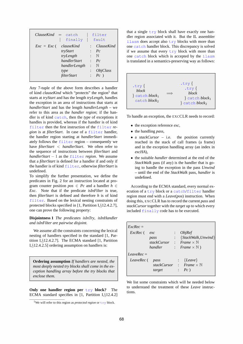
ClauseKind = catch | filter| finally | fault
Exc = Exc( clauseKind : ClauseKindtryStart : PctryLength : NhandlerStart : PchandlerLength : Ntype : ObjClassfilterStart : Pc )
Any 7-tuple of the above form describes a handlerof kind clauseKindwhich “protects” the region5 thatstarts attryStartand has the lengthtryLength, handlesthe exception in an area of instructions that starts athandlerStartand has the lengthhandlerLength– werefer to this area as thehandler region; if the han-dler is of kindcatch , then thetypeof exceptions ithandles is provided, whereas if the handler is of kindfilter then the first instruction of thefilter re-gion is at filterStart. In case of afilter handler,the handler region starting athandlerStart immedi-ately follows thefilter region – consequently wehave filterStart < handlerStart. We often refer tothe sequence of instructions betweenfilterStart andhandlerStart− 1 as thefilter region. We assumethat afilterStart is defined for a handler if and only ifthe handler is of kindfilter , otherwisefilterStart isundefined.To simplify the further presentation, we define thepredicates in Fig. 2 for an instruction located at pro-gram counter positionpos ∈ Pc and a handlerh ∈Exc. Note that if the predicateisInFilter is true,then filterStart is defined and thereforeh is of kindfilter . Based on the lexical nesting constraints ofprotected blocks specified in [1, Partition I,§12.4.2.7],one can prove the following property:
Disjointness 1 The predicates isInTry, isInHandlerand isInFilter are pairwise disjoint.
We assume all the constraints concerning the lexicalnesting of handlers specified in the standard [1, Par-tition I,§12.4.2.7]. The ECMA standard [1, PartitionI,§12.4.2.5] ordering assumption on handlers is:
Ordering assumption If handlers are nested, themost deeply nested try blocks shall come in the ex-ception handling array before the try blocks thatenclose them.
Only one handler region per try block? TheECMA standard specifies in [1, Partition I,§12.4.2]
5We will refer to this region asprotected regionor try block.
that a singletry block shall have exactly one han-dler region associated with it. But the IL assemblerilasm does accept alsotry blocks with more thanonecatch handler block. This discrepancy is solvedif we assume that everytry block with more thanone catch block which is accepted by theilasmis translated in a semantics-preserving way as follows:
.try {block
} catch block1catch block2
=⇒
.try {.try {
block} catch block1
} catch block2
To handle an exception, theEXCCLR needs to record:
• the exception referenceexc,
• the handlingpass,
• a stackCursor – i.e. the position currentlyreached in the stack of call frames (a frame)and in the exception handling array (an index inexcHA),
• the suitablehandlerdetermined at the end of theStackWalkpass (if any) is the handler that is go-ing to handle the exception in the passUnwind– until the end of theStackWalkpass,handler isundefined.
According to the ECMA standard, every normal ex-ecution of atry block or acatch /filter handlerregion must end with aLeave(pos) instruction. Whendoing this,EXCCLR has to record the currentpassandstackCursortogether with thetargetup to which everyincludedfinally code has to be executed.
ExcRec=
ExcRec( exc : ObjRefpass : {StackWalk,Unwind}stackCursor : Frame× Nhandler : Frame× N )
LeaveRec=
LeaveRec( pass : {Leave}stackCursor : Frame× Ntarget : Pc )
We list some constraints which will be needed belowto understand the treatment of theseLeave instruc-tions.
68

Fig. 2 The predicatesisInTry, isInHandlerandisInFilter
isInTry(pos, h) ⇔ tryStart(h) ≤ pos< tryStart(h) + tryLength(h)isInHandler(pos, h) ⇔ handlerStart(h) ≤ pos< handlerStart(h) + handlerLength(h)isInFilter(pos, h) ⇔ filterStart(h) ≤ pos< handlerStart(h)
Syntactic constraints:
1. It is not legal to exit with aLeaveinstructiona filter region, afinally /fault han-dler region.
2. It is not legal to branch with aLeaveinstruc-tion into a handler region from outside the re-gion.
3. It is legal to exit with aLeave a catchhandler region and branch to any instructionwithin the associatedtry block, so long asthat branch target is not protected by yet an-othertry block.
The nesting of passes determinesEXCCLR to main-tain an initially empty stack of exception or leaverecords for the passes that are still to be performed.
passRecStack: List(ExcRec∪ LeaveRec)passRecStack= [ ]
In the initial state ofEXCCLR, there is no pass tobe executed, i.e.pass= undef.
We can now summarize the overall behavior ofEXCCLR, which is defined in Fig. 3 and analyzedin detail in the following sections, by saying that ifthere is a handler in the frame defined bystackCursor,then EXCCLR will try to find (when StackWalking)or to execute (whenUnwinding) or to leave (whenLeaveing) the corresponding handler; otherwise it willcontinue its work in the invoker frame or end itsLeavepass at thetarget.
5 THE StackWalkPASS
During aStackWalkpass,EXCCLR starts in the cur-rent frameto search for a suitable handler of the cur-rent exception in this frame. Such a handler exists ifthe search positionn in the current frame has not yetreached the last element of the handlers arrayexcHAof the corresponding methodm.
existsHanWithinFrame(( , , , , , m), n) ⇔n < length(excHA(m))
If there are no (more) handlers in the frame pointedto by stackCursor, then the search has to be contin-
ued at the invoker frame. This means to reset thestackCursorto point to the invoker frame.
SEARCHINVFRAME(f ) ≡let · [f ′, f ] · = frameStack· [frame] in
RESET(stackCursor, f ′)
There are three groups of possible handlershEXCCLR is looking for in a given frame during itsStackWalk:
• a catch handler whosetry block protects theprogram counterpc of the frame pointed at bystackCursorand whosetypeis a supertype of theexception type;
matchCatch(pos, t, h) ⇔isInTry(pos, h) ∧ clauseKind(h) = catch ∧t � type(h)
• a filter handler whosetry block protects thepcof the frame pointed at bystackCursor;
matchFilter(pos, h) ⇔isInTry(pos, h) ∧ clauseKind(h) = filter
• a filter handler whosefilter region con-tainspc of the frame pointed at bystackCursor.This corresponds to an outer exception and willbe described in more detail below.
The order of theif clauses in thelet statement from theruleStackWalkis not important. This is justified by thefollowing property:
Disjointness 2 For every type t, the predicatesmatchCatcht, matchFilter and isInFilter are pairwisedisjoint6.
The above property can be easily proved using the def-initions of the three predicates and the propertyDis-jointness1.
If the handler pointed to by thestackCursor, namelyhanWithinFrame(( , , , , , m), n) = excHA(m)(n),is not of any of the above types, thestackCursorisincremented to point to the next handler in theexcHA:
6By matchCatcht we understand the predicate defined by the set{(pos, h) | matchCatch(pos,t,h)}.
69

GOTONXTHAN ≡ stackCursor:= (f , n + 1)where stackCursor= (f , n)
The Ordering assumptionstated in Section 4 andthe lexical nesting constraints stated in [1, PartitionI,§12.4.2.7] ensure that if thestackCursorpoints to ahandler of one of the above types then this handler isthe first handler in the exception handling array (start-ing at the position indicated in thestackCursor) of anyof the above types.
If the handler pointed to by thestackCursor isa matching7 catch then this handler becomes thehandler to handle the exception in the passUnwind.ThestackCursoris reset to be reused for theUnwindpass: it shall point to the faulting frame, i.e. the cur-rent frame. Note that duringStackWalk, framealwayspoints to the faulting frame except in case afilterregion is executed. However, the frame built to executea filter is never searched for a handler correspond-ing to the current exception.
FOUNDHANDLER ≡pass:= Unwindhandler:= stackCursor
RESET(s, f ) ≡ s := (f , 0)
If the handler is afilter then by means ofEXECFILTER its filter region is executed. The ex-ecution is performed in a separate frame constructedespecially for this purpose. However this importantdetail is omitted by the ECMA standard [1]. Thecurrently-to-be-executed frame becomes the frame forexecuting thefilter region. The faulting excep-tion frame is pushed on theframeStack. The currentframe points now to the method, local variables andarguments of the frame in whichstackCursoris, ithas the exception reference on the evaluation stackevalStackand the program counterpc set to the be-ginningfilterStart of the filter region. Theswitchis set toNoswitchin order to pass the control to thenormal machineEXECCLRE .
7We use theactualTypeOffunction defined in [7] to determinethe run-time type of the exception.
Fig. 3 The exception handling machineEXCCLREXCCLR ≡
match passStackWalk→
if existsHanWithinFrame(stackCursor) thenlet h = hanWithinFrame(stackCursor) in
if matchCatch(pos, actualTypeOf(exc), h) thenFOUNDHANDLER
RESET(stackCursor, frame)elseifmatchFilter(pos, h) then EXECFILTER(h)elseif isInFilter(pos, h) then EXIT INNEREXC
elseGOTONXTHAN
else SEARCHINVFRAME(f )where stackCursor= (f , ) and f = (pos, , , , )
Unwind→if existsHanWithinFrame(stackCursor) then
let h = hanWithinFrame(stackCursor) inif matchTargetHan(handler, stackCursor) then
EXECHAN(h)elseifmatchFinFault(pc, h) then
EXECHAN(h)GOTONXTHAN
elseif isInHandler(pc, h) thenABORTPREVPASSREC
GOTONXTHAN
elseif isInFilter(pc, h) thenCONTINUEOUTEREXC
elseGOTONXTHAN
elsePOPFRAME
SEARCHINVFRAME(frame)
Leave→if existsHanWithinFrame(stackCursor) then
let h = hanWithinFrame(stackCursor) inif isFinFromTo(h, pc, target) then
EXECHAN(h)if isRealHanFromTo(h, pc, target) then
ABORTPREVPASSREC
GOTONXTHAN
elsepc := targetPOPREC
switch:= Noswitch
EXECFILTER(h) ≡pc := filterStart(h)evalStack:= [exc]locAdr := locAdr′
argAdr := argAdr′
meth:= meth′
PUSHFRAME
switch:= Noswitchwhere stackCursor=
(( , locAdr′, argAdr′, , meth′), )
Exceptions in filter region? It is not documentedin the ECMA standard what happens if an (inner) ex-ception is thrown while executing thefilter regionduring theStackWalkpass of an outer exception. The
70

following cases are to be considered:
• if the exception is taken care of in thefilterregion, i.e. it is successfully handled by acatch /filter handler or it is aborted becauseit occured in yet anotherfilter region of anested handler (see theisInFilter clause), then thegiven filter region continues executing nor-mally (after the exception has been taken care of);
• if the exception is not taken care of in thefilter region then the exception is not prop-agated further, but itsStackWalkis exited (seeFig. 3). The exception will be discarded but onlyafter theEXCCLR runs itsUnwind pass to exe-cute all thefinally andfault handlers (seeTests 6, 8 and 9 in [5]).
EXIT INNEREXC ≡pass:= UnwindRESET(stackCursor, frame)
6 THE Unwind PASS
As soon as the passStackWalk terminates,the EXCCLR starts the Unwind pass with thestackCursorpointing to the faulting exception frame.Starting there, one has to walk down to thehandlerde-termined in theStackWalk, executing on the way ev-ery finally /fault handler region. This happensalso in casehandler is undef. WhenUnwinding, theEXCCLR searches for
• the matching target handler, i.e. thehandlerde-termined at the end of theStackWalkpass (ifany) –handlercan beundef if the search in theStackWalkhas been exited because the exceptionwas thrown in afilter region. Also the twohandlerandstackCursorframes in question haveto coincide. We say that two frames are the sameif the address arrays of their local variables andarguments as well as their method names coin-cide.
matchTargetHan((f1, n1), (f2, n2)) ⇔sameFrame(f1, f2) ∧ n1 = n2
sameFrame(f1, f2) ⇔pri(f1) = pri(f2),∀i ∈ {2, 3, 5}
• a matchingfinally /fault handler whose as-sociatedtry block protects thepc;
matchFinFault(pos, h) ⇔isInTry(pos, h)∧clauseKind(h) ∈ {finally , fault }
• a handler whose handler region containspc;
• a filter handler whosefilter region con-tainspc;
The order of the last threeif clauses in thelet statementfrom the ruleUnwind is not important. It only mattersthat the first clause is guarded bymatchTargetHan.
Disjointness 3 The following predicates are pairwisedisjoint: matchFinFault, isInHandler and isInFilter.
The property can be proved using the definitions of thepredicates and the propertyDisjointness1.
The Ordering assumptionin Section 4 and thelexical nesting constraints given in [1, PartitionI,§12.4.2.7] ensure that if thestackCursorpoints to ahandler of one of the above types then this handler isthe first handler in the exception handling array (start-ing at the position indicated in thestackCursor) of anyof the above types.
If the handler pointed to by thestackCursoris thehandler found in theStackWalk, its handler region isexecuted through EXECHAN: the pc is set to the be-ginning of the handler region, the exception referenceis loaded on the evaluation stack (when EXECHAN isapplied for executingfinally /fault handler re-gions the current exception is not pushed onevalStack)and the control switches toEXECCLRE .
EXECHAN(h) ≡pc := handlerStart(h)evalStack:=
if clauseKind(h) ∈ {catch , filter } then[exc]
else[ ]
switch:= Noswitch
If the handler pointed to by thestackCursoris amatching finally /fault handler, its handler re-gion is executed with initially empty evaluation stack.At the same time, thestackCursor is incrementedthrough GOTONXTHAN.
Let us assume that the handler pointed to bystackCursoris an arbitrary handler whose handler re-gion containspc.Exceptions in handler region?The ECMA standarddoes not specify what should happen if an exception israised in a handler region. The experimentation in [5]can be resumed by the following rules of thumb forexceptions thrown in a handler region similarly to thecase of nested exceptions infilter code:
• if the exception is taken care of in the han-dler region, i.e. it is successfully handled by a
71

catch /filter handler or it is discarded (be-cause it occured in afilter region of a nestedhandler), then the handler region continues exe-cuting normally (after the exception is taken careof);
• if the exception is not taken care of in the handlerregion, i.e, escapes the handler region, then
– the previous pass ofEXCCLR is abortedthrough ABORTPREVPASSREC;
ABORTPREVPASSREC≡ pop(passRecStack)
– the exception is propagated further, i.e. theUnwind pass continues via GOTONXTHAN (seeFig. 3) which sets thestackCursorto the nexthandler inexcHA.
The execution of a handler region can only occurwhenEXCCLR runs in theUnwindandLeavepasses:in Unwind handler regions of any kind are executedwhereas inLeave only finally handler regionsare executed. If the raised exception occured whileEXCCLR runs anUnwind pass for handling an outerexception, theUnwind pass of the outer exception isstopped and the corresponding pass record is poppedfrom passRecStack(seeTests 1, 3 and 4 in [5]). Ifthe exception has been thrown whileEXCCLR runs aLeavepass for executingfinally handlers on theway from aLeaveinstruction to its target, then thispass is stopped and its associated pass record is poppedoff passRecStack(seeTest 2 in [5]).In this way an exception can go “unhandled” withouttaking down the process, namely if an outer exceptiongoes unhandled, but an inner exception is successfullyhandled (see the second case of the preceding case dis-tinction).
If the handler pointed to by thestackCursor isa filter handler whosefilter region containspc, then the current (inner) exception is aborted andthe filter considered as not providing a handlerfor the outer exception. So there is no way toexit a filter region with an exception. This en-sures that the frame built by EXECFILTER for exe-cuting a filter region is used only for this pur-pose. The handling of the outer exception is con-tinued through CONTINUEOUTEREXC (see Fig. 3)which pops the frame built for executing thefilterregion, pops from thepassRecStackthe pass recordcorresponding to the inner exception and reestablishesthe pass context of the outer exception, but withthestackCursorpointing to the handler following thejust inspectedfilter handler. The updates of thestackCursorin POPREC and GOTONXTHAN are donesequentially such that the update in GOTONXTHAN
overwrites the update in POPREC.
CONTINUEOUTEREXC ≡POPFRAME
POPREC seqGOTONXTHAN
POPREC≡if passRecStack= [ ] then
SETRECUNDEF
switch:= Noswitchelse let(passRecStack′, [r]) =
split(passRecStack, 1) inif r ∈ ExcRecthen
let (exc′, pass′, stackCursor′, handler′) = r inexc := exc′
pass := pass′
stackCursor:= stackCursor′
handler := handler′
if r ∈ LeaveRecthenlet (pass′, stackCursor′, target′) = r inpass := pass′
stackCursor:= stackCursor′
target := target′
passRecStack:= passRecStack′
SETRECUNDEF≡exc := undefpass := undefstackCursor:= undeftarget := undefhandler := undef
If the handler pointed to by thestackCursoris not ofany of the above types, thestackCursoris incrementedto point to the next handler in theexcHA.
If the Unwindpass exhausted all the handlers in theframe indicated instackCursorthen the current frameis popped fromframeStackand theUnwindpass con-tinues in the invoker frame of the current frame.Exceptions in class initializers? If an exception oc-curs in a class initializer.cctor then the class shallbe marked as being in a specific erroneous state anda TypeInitializationException is thrown.This means that an exception can and will escapethe body of an initializer only by the specific ex-ceptionTypeInitializationException . Anyfurther attempt to access the corresponding class inthe current application domain will throwthe sameTypeInitializationException object. Un-fortunately, this detail is not specified by the ECMAstandard but it seems to correspond to the actualCLR implementation and it complies with the re-lated specification for C] in the ECMA standard (seeTest 7 in [5]). Therefore we assume that thecode sequence of every.cctor is embedded into
72

a catch handler. Thiscatch handler catches ex-ceptions of typeObject , i.e. any exception, oc-cured in.cctor , discards it, creates an object of typeTypeInitializationException 8 and throwsthe new exception.
7 THE LeavePASS
The EXCCLR machine gets into theLeave passwhenEXECCLRE executes aLeaveinstruction uponthe normal termination of atry block or of acatch /filter handler region. One has to exe-cute the handler regions of allfinally handlers onthe way from theLeave instruction to the instruc-tion whose program counter is given by theLeavetarget parameter. ThestackCursorused in theLeavepass is initialized by theLeave instruction. In theLeavepass, theEXCCLR machine searches for
• finally handlers that are “on the way” fromthepc to thetarget,
• real handlers, i.e.catch /filter handlers thatare “on the way” from thepc to thetarget– moredetails are given below.
If the handler pointed to bystackCursor is afinally handler on the way frompc to thetargetpo-sition of the currentLeavepass record then the handlerregion of this handler is executed (see Fig. 3). If thestackCursorpoints to acatch /filter handler onthe way frompc to targetthen the previous pass recordon passRecStackis discarded (see Fig. 3). The dis-carded record can only be referring to anUnwindpassfor handling an exception. By discarding this record,the mechanism terminates the handling of the corre-sponding exception.
isFinFromTo(h, pos1, pos2) ⇔isInTry(pos1, h) ∧ clauseKind(h) = finally ∧¬isInTry(pos2, h) ∧ ¬isInHandler(pos2, h)
isRealHanFromTo(h, pos1, pos2) ⇔clauseKind(h) ∈ {catch , filter }∧isInHandler(pos1, h) ∧ ¬isInHandler(pos2, h)
For each handlerEXCCLR inspects also the nexthandler inexcHA. When the handlers in the currentmethod are exhausted,pc is set totarget, the contextof the previous pass record onpassRecStackis reestab-lished and the control is passed to normalEXECCLRE
execution (see Fig. 3).
8In the real CLR implementation, the exception thrownin .cctor is embedded as an inner exception in theTypeInitializationException . We do not modelthis aspect here.
8 THE RULES OF EXECCLRE
The rules ofEXECCLRE in Fig. 4 specify the effectof the CIL instructions related to exceptions. Each ofthese rules transfers the control toEXCCLR. Throwpops the topmost evaluation stack element (seeRe-mark below), which is supposed to be an exceptionreference. It loads onEXCCLR the pass record as-sociated to the given exception: thestackCursorisinitialized by the currentframe and 0. If the ex-ception mechanism is already working in a pass, i.e.pass 6= undef then the current pass record is pushedonpassRecStack.
LOADREC(r) ≡if r ∈ ExcPassthen
let (exc′, pass′, stackCursor′, handler′) = r inexc := exc′
pass := pass′
stackCursor:= stackCursor′
handler := handler′
else let(pass′, stackCursor′, target′) = r inpass := pass′
stackCursor:= stackCursor′
target := target′
if pass6= undef then PUSHREC
PUSHREC≡if pass= Leavethen
push(passRecStack, (pass, stackCursor, target))elsepush(passRecStack,
(exc, pass, stackCursor, handler))
If the exception reference popped from theevalStack by the Throw instruction is null , aNullReferenceException is thrown. For agiven classc, the macro RAISE(c) is defined by thefollowing code template9:
RAISE(c) ≡NewObj(c :: .ctor )Throw
This macro can be viewed as a static method defined inclassObject . Calling the macro is then like invokingthe corresponding method.
The ECMA standard states in [1, Partition III,§4.23]that theRethrowinstruction is only permitted withinthe body of acatch handler. However, the same in-struction is allowed also within a handler region ofa filter (seeTest 5 in [5]) even if this does not
9The NewObj instruction called with an instance constructorc ::.ctor creates a new object of classc and then calls the con-structor.ctor .
73
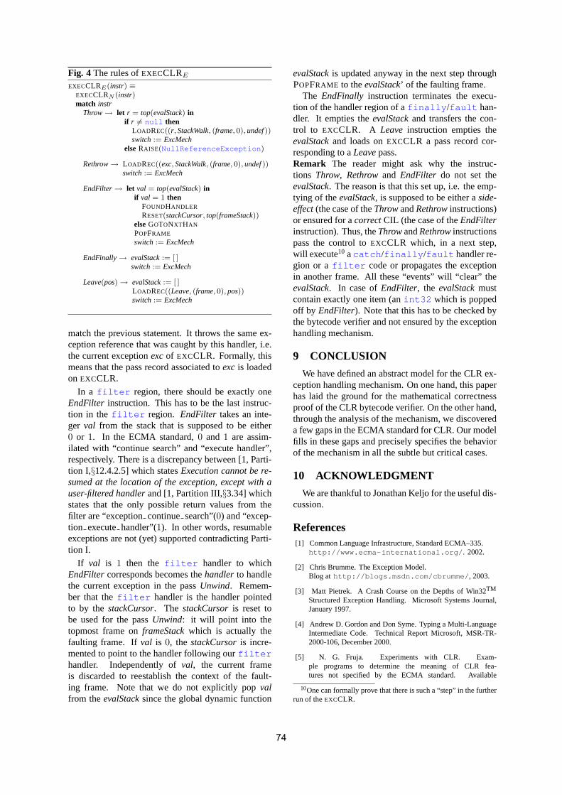
Fig. 4 The rules ofEXECCLRE
EXECCLRE(instr) ≡EXECCLRN (instr)match instr
Throw→ let r = top(evalStack) inif r 6= null then
LOADREC((r, StackWalk, (frame, 0), undef))switch:= ExcMech
elseRAISE(NullReferenceException )
Rethrow→ LOADREC((exc, StackWalk, (frame, 0), undef))switch:= ExcMech
EndFilter→ let val = top(evalStack) inif val = 1 then
FOUNDHANDLER
RESET(stackCursor, top(frameStack))elseGOTONXTHAN
POPFRAME
switch:= ExcMech
EndFinally→ evalStack:= [ ]switch:= ExcMech
Leave(pos) → evalStack:= [ ]LOADREC((Leave, (frame, 0), pos))switch:= ExcMech
match the previous statement. It throws the same ex-ception reference that was caught by this handler, i.e.the current exceptionexcof EXCCLR. Formally, thismeans that the pass record associated toexcis loadedon EXCCLR.
In a filter region, there should be exactly oneEndFilter instruction. This has to be the last instruc-tion in the filter region. EndFilter takes an inte-ger val from the stack that is supposed to be either0 or 1. In the ECMA standard,0 and 1 are assim-ilated with “continue search” and “execute handler”,respectively. There is a discrepancy between [1, Parti-tion I,§12.4.2.5] which statesExecution cannot be re-sumed at the location of the exception, except with auser-filtered handlerand [1, Partition III,§3.34] whichstates that the only possible return values from thefilter are “exceptioncontinue search”(0) and “excep-tion executehandler”(1). In other words, resumableexceptions are not (yet) supported contradicting Parti-tion I.
If val is 1 then the filter handler to whichEndFilter corresponds becomes thehandlerto handlethe current exception in the passUnwind. Remem-ber that thefilter handler is the handler pointedto by thestackCursor. The stackCursoris reset tobe used for the passUnwind: it will point into thetopmost frame onframeStackwhich is actually thefaulting frame. Ifval is 0, the stackCursoris incre-mented to point to the handler following ourfilterhandler. Independently ofval, the current frameis discarded to reestablish the context of the fault-ing frame. Note that we do not explicitly popvalfrom theevalStacksince the global dynamic function
evalStackis updated anyway in the next step throughPOPFRAME to theevalStack’ of the faulting frame.
The EndFinally instruction terminates the execu-tion of the handler region of afinally /fault han-dler. It empties theevalStackand transfers the con-trol to EXCCLR. A Leave instruction empties theevalStackand loads onEXCCLR a pass record cor-responding to aLeavepass.Remark The reader might ask why the instruc-tions Throw, Rethrowand EndFilter do not set theevalStack. The reason is that this set up, i.e. the emp-tying of theevalStack, is supposed to be either aside-effect(the case of theThrowandRethrowinstructions)or ensured for acorrectCIL (the case of theEndFilterinstruction). Thus, theThrowandRethrowinstructionspass the control toEXCCLR which, in a next step,will execute10 acatch /finally /fault handler re-gion or afilter code or propagates the exceptionin another frame. All these “events” will “clear” theevalStack. In case ofEndFilter, the evalStackmustcontain exactly one item (anint32 which is poppedoff by EndFilter). Note that this has to be checked bythe bytecode verifier and not ensured by the exceptionhandling mechanism.
9 CONCLUSION
We have defined an abstract model for the CLR ex-ception handling mechanism. On one hand, this paperhas laid the ground for the mathematical correctnessproof of the CLR bytecode verifier. On the other hand,through the analysis of the mechanism, we discovereda few gaps in the ECMA standard for CLR. Our modelfills in these gaps and precisely specifies the behaviorof the mechanism in all the subtle but critical cases.
10 ACKNOWLEDGMENT
We are thankful to Jonathan Keljo for the useful dis-cussion.
References[1] Common Language Infrastructure, Standard ECMA–335.
http://www.ecma-international.org/ . 2002.
[2] Chris Brumme. The Exception Model.Blog at http://blogs.msdn.com/cbrumme/ , 2003.
[3] Matt Pietrek. A Crash Course on the Depths of Win32TM
Structured Exception Handling. Microsoft Systems Journal,January 1997.
[4] Andrew D. Gordon and Don Syme. Typing a Multi-LanguageIntermediate Code. Technical Report Microsoft, MSR-TR-2000-106, December 2000.
[5] N. G. Fruja. Experiments with CLR. Exam-ple programs to determine the meaning of CLR fea-tures not specified by the ECMA standard. Available
10One can formally prove that there is such a “step” in the furtherrun of theEXCCLR.
74
at http://www.inf.ethz.ch/personal/fruja/publications/clrexctests.pdf
[6] N. G. Fruja. Type Safety in C] and .NET CLR. PhD Thesis inpreparation.
[7] N. G. Fruja. A Modular Design for the .NET CLR Architec-ture. Proceedings of the Workshop on Abstract State Machines,ASM’05, France.
[8] E. Borger, N. G. Fruja, V. Gervasi, R. F. Stark. A High–LevelModular Definition of the Semantics of C]. Journal TheoreticalComputer Science, June, 2005.
[9] R. F. Stark and E. Borger. An ASM Specification of C#Threads and the .NET memory model. Proceedings of theWorkshop on Abstract State Machines,ASM’04, Germany,Springer LNCS 3052 (2004) pag. 38–60.
[10] E. Borger and R. F. Stark. Exploiting Abstraction for Speci-fication Reuse: The Java/C# Case Study. Formal Methods forComponents and Objects: Second International Symposium,FMCO’03, The Netherlands, Springer LNCS 3188 (2004),pag. 42–76.
[11] N. G. Fruja. Specification and Implementation Problems forC]. Proceedings of the Workshop on Abstract State MachinesASM’04, Germany, Springer LNCS 3052, pag. 127–143.
[12] N. G. Fruja. The Correctness of the Definite Assignment Anal-ysis in C]. Journal of Object Technology, vol. 3, no. 9, 2004.
[13] H. V. Jula and N.G. Fruja. An Executable Specification ofC]. Proceedings of the Workshop on Abstract State Machines,ASM’05, France.
[14] C. Marrocco. An Executable Specification of the .NET CLR.Diploma Thesis supervised by N. G. Fruja, ETH Zurich, 2005.
[15] R. F. Stark, J. Schmid, E. Borger. Java and the Java Vir-tual Machine–Definition, Verification, Validation. Springer–Verlag, 2001.
[16] E. Borger and W. Schulte. A Practical Method for Specifica-tion and Analysis of Exception Handling – a Java JVM CaseStudy. IEEE Transactions of Software Engineering, vol. 26,2000.
[17] E. Borger and R. F. Stark. Abstract State Machines–A Methodfor High-Level System Design and Analysis. Springer-Verlag,2003.
[18] Abstract State Machine Language (AsmL), Founda-
tions of Software Engineering Group, Microsoft Research,
Web pages at http://research.microsoft.com/
foundations/AsmL/ .
75

76
Designing and Implementing a MANET Network Service Interface with Compact .NET on Pocket PC
Fabio De Rosa
Università di Roma “La Sapienza” Dipartimento di Informatica e Sistemistica
Via Salaria 113 (2nd floor, lab C4) I-00198 Roma, Italy
Massimo Mecella Università di Roma “La Sapienza”
Dipartimento di Informatica e Sistemistica Via Salaria 113 (2nd floor, room 231)
I-00198 Roma, Italy
ABSTRACT Operators forming an ad hoc network (MANET) in emergency situations would benefit from software supporting their interaction. To date, however, development of such a coordination layer has required abstractions on the services and data provided by the lower network layers. In this paper we present the design and a possible implementation of the Network Service Interface [DeRosa03a] as a .NET Compact Framework component, coded in C#, to be run on PDAs with the Windows Mobile operating system. We chose Dynamic Source Routing (DSR) as the routing protocol supporting inter-device communication.
Keywords Cooperative Work – Mobile Ad hoc Network – Network Service Interface – Object and Component Design – .NET Compact Framework – DSR.
1. INTRODUCTION The widespread availability of network-enabled hand-held devices (e.g. PDAs with WiFi - the 802.11x-based standard) has made pervasive computing environment development an emerging reality. Mobile (or Multi-hop) Ad hoc NETworks (MANETs, [Agrawal03a]) are mobile device networks communicating with one another via wireless links without relying on an underlying infrastructure. This distinguishes them from other types of wireless networks, such as cell networks or infrastructure-based wireless networks. Each device in a MANET acts as an endpoint and as a router forwarding messages to devices within radio range. MANETs are a sound alternative to infrastructure-based networks whenever the infrastructure is lacking or unusable, such as in emergency situations.
Operators acting in such emergency situations would benefit from software supporting their collaboration. Such a coordination layer would enable them to execute sets of activities (in sequence, concurrently, etc.) through specific applications (e.g. computer supported cooperative work - CSCW - tools [Grudin04a], workflow management applications [Leymann00a], etc.) running on hand-held devices, thus enabling cooperative processes to be run. All such applications typically require continuous inter-device connections (e.g. for data/information sharing, activity scheduling and coordination, etc.), but these are not generally guaranteed in MANETs.
We investigated a specific pervasive architecture, targeted at CSCW and workflow management applications constituting the coordination layer and able to maintain continuous connections among MANET devices.
Permission to make digital or hard copies of all or part of this work for personal or classroom use is granted without fee provided that copies are not made or distributed for profit or commercial advantage and that copies bear this notice and the full citation on the first page. To copy otherwise, or republish, to post on servers or to redistribute to lists, requires prior specific permission and/or a fee. .NET Technologies’2005 conference proceedings, ISBN 80-86943-01-1 Copyright UNION Agency – Science Press, Plzen, Czech Republic
As a typical example, consider the aftermath of an archeological disaster: following an earthquake, a team is equipped with mobile devices (laptops and PDAs) and sent to the affected area to evaluate the condition of archeological sites and buildings, with the goal of drawing a situation map to schedule rebuilding activities. A typical cooperative process to be enacted by the team would be that shown in Figure 1 (depicted as an UML Activity Diagram):
77

• the team leader has previously stored all area details (not included in the process), including a site map, list of the most important objects located in the site and previous reports/materials;
• the team is considered as an overall MANET, in which the team leader’s device (requiring the most computing power, therefore usually a laptop) coordinates the other team members’ devices, by providing suitable information (e.g. maps, sensitive objects, etc.) and assigning activities/tasks;
• team members are equipped with hand-held devices (PDAs), which allow them to run some operations but do not have much computing power. Such operations, possibly involving various hardware items (e.g. digital cameras, GPRS connections, computing power for image processing, main storage, etc.), are provided as software services to be coordinated. Team member 1 might compile some specific questionnaires (after a visual analysis of a building), to be analyzed by the team leader using specific software in order to schedule subsequent activities; team member 3 might take pictures of the damaged buildings, while team member 2 may be responsible for specific processing of previous and recent pictures (e.g. for initial identification of architectural anomalies).
In this case, it might be useful to match new pictures with previously stored images. The device holding the high-resolution camera must therefore be connected to the one containing the stored pictures.
But in a situation such as that shown in Figure 2, the movement of the operator/device equipped with the camera may result in its disconnection from the others.
A pesuch possi4’s dout ensurcoordactividiscoactivi
The pby tknowtakesbe sa
In refocusprotootherEffecactivesomeliterahoc OZone
Team Member 2 (picture store device)
Team Member 3 (camera device)
Compile Select Building
Selected Building
Go to Destination
Zoom on damaged part
Send Photos Photos
Matching
Compile
Result
Data
Team Leader Team Member 1
Capture Scene
Museum
Precarious
Bell-Tower Building
Church
Hit Area
Picture Store
Operator
Bridge
Team Leader
Camera
Movement needed to accomplish the task
Movement needed to maintain the network connectivity; should be adaptively driven by the cooperative application
Figure 1. Cooperative process.
78
Figure 2. Critical situation and adaptive management.
rvasive architecture should be able to predict a situation, alert the coordination layer, and bly have a “bridging” device (team member evice) to follow the operator/device moving of range, maintaining the connection and ing a path between devices. In this way the ination layer schedules the execution of new ties based on the prediction of a nnection, as shown in Figure 3 (note the new ty for team member 4).
rocess’s adaptive change is centrally managed he coordination layer, which has “global” ledge of the status of all operators/devices and into account idle devices, operations that can fely delayed, etc.
cent years, research in the MANET area has ed on the development of appropriate routing cols, methods for energy preservation, and issues on the lower four ISO/OSI layers. tive routing in ad hoc networks is still an ly-addressed open problem [Vaidya04a], with
interesting proposals presented in the ture (e.g. Dynamic Source Routing – DSR, Ad n demand Distance Vector – AODV routing,
Routing Protocol - Z-RP, etc.).

To da(and has charagenerlowernetwolayer startinroutin
In thiimple[DeRcompthe WSourcsuppoknowof a Mmainlcommlaptop
The pworkfframedescrthe reshow
layer, while in Section 4 we report the results of NSI component testing experiments. In Section 5 an example of Windows Mobile application –MANET-Chat – is described, to show the use of the NSI component. Finally in Section 6 we report our conclusions and future work.
2. WORKFLOW ARCHITECTURE Figure 4 shows the architecture supporting cooperative work on MANETs. The various MANET devices are equipped with some wireless network interfaces and specific hardware for calculating distances from neighboring devices (Wireless Stack in the figure), while the Network Service Interface (NSI) provides the upper layers with the basic services for sending and receiving messages (through multi-hop paths) to/from other devices, by abstracting the specific routing protocols.
Services (i.e. specific applications supporting the device users’ tasks 1) are accessible to other devices and can be coordinated and composed in a cooperative process. In contrast, the coordinator device presents the Predictive Layer on top of the Network Service Interface, signaling any probable disconnection to the upper Coordination Layer.
Go to destination
Zoom on damaged part
Send Photos Photos
Team Member 3 (camera device)
Team Member 4 (bridge device)
Capture Scene
Follow Team member 3
Matching
Team Member 2 (picture store device)
Selected Building
Select Building
Figure 3. Modified process (details).te, development of application layer software thus of any information system for MANET), required abstractions on the specific cteristics of the routing algorithms and, more ally, on the services and data provided by the network layers. [DeRosa03a] proposes a rk service interface to be used as the basic on which to build application software, g from the analysis and abstraction of current g protocols.
s paper we present the design and a possible mentation of the Network Service Interface osa03a] layer as a .NET Compact Framework onent, coded in C#, to be run on PDAs with indows Mobile operating system. Dynamic
e Routing was chosen as the routing protocol rting inter-device communication . To our ledge, this is the first effective implementation ANET routing protocol for PDAs (which are
y Windows-based); current research and the ercial tools available are targeted only at s running Linux.
aper is organized as follows: in Section 2, the low architecture constituting the reference work for cooperative work on MANET is ibed; this provides the overall framework for sults presented in this paper. In Section 3 we the design of the Network Service Interface
The Predictive Layer implements a probabilistic technique [DeRosa05a] which can predict if all devices will still be connected in the successive moment. At a given time instant ti in which all devices are connected, the coordinator device collects all device distance information and builds a next connection graph, i.e. the most likely graph at the next time instant ti+1, in which the predicted connected and disconnected devices are highlighted. In the interval [ ti, ti+1 ], the coordinator layer enacts the appropriate actions to enable all devices to be still connected at ti+1. In predicting at ti the next connection graph, the technique considers not only the current situation, but also recent situations and predictions (i.e., at ti-1, ti-2, etc.), specifically considering distances calculated in the recent past. Thus, although the pervasive architecture guarantees that constant connection of all devices, MANET’s evolution is considered as it would be in a “free” scenario (i.e. without remedial actions by the coordination layer) when predicting the future situation. The
1 Some of these services are applications that do not
require human intervention (e.g. an image processing utility), whereas others act as proxies in front of human actors (e.g. the service for instructing human actors to follow a peer is a simple GUI that alerts the human operator by displaying a pop-up window and emitting a signal).
79
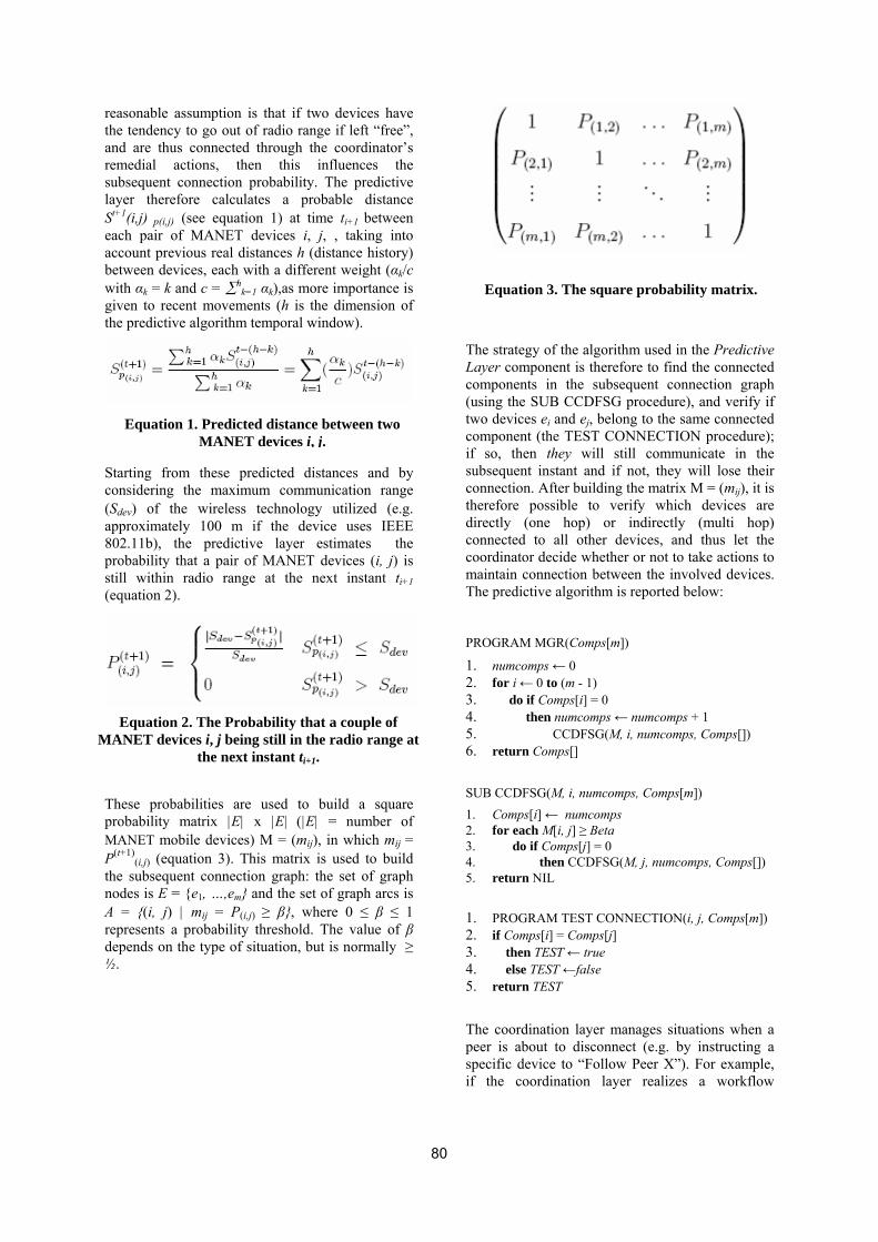
reasonable assumption is that if two devices have the tendency to go out of radio range if left “free”, and are thus connected through the coordinator’s remedial actions, then this influences the subsequent connection probability. The predictive layer therefore calculates a probable distance St+1(i,j) p(i,j) (see equation 1) at time ti+1 between each pair of MANET devices i, j, , taking into account previous real distances h (distance history) between devices, each with a different weight (αk/c with αk = k and c = ∑h
k=1 αk),as more importance is given to recent movements (h is the dimension of the predictive algorithm temporal window).
Starting from these predicted distances and by considering the maximum communication range (Sdev) of the wireless technology utilized (e.g. approximately 100 m if the device uses IEEE 802.11b), the predictive layer estimates the probability that a pair of MANET devices (i, j) is still within radio range at the next instant ti+1 (equation 2).
These probabilities are used to build a square probability matrix |E| x |E| (|E| = number of MANET mobile devices) M = (mij), in which mij = P(t+1)
(i,j) (equation 3). This matrix is used to build the subsequent connection graph: the set of graph nodes is E = {e1, …,em} and the set of graph arcs is A = {(i, j) | mij = P(i,j) ≥ β}, where 0 ≤ β ≤ 1 represents a probability threshold. The value of β depends on the type of situation, but is normally ≥ ½.
Equation 3. The square probability matrix.
The strategy of the algorithm used in the Predictive Layer component is therefore to find the connected components in the subsequent connection graph (using the SUB CCDFSG procedure), and verify if two devices ei and ej, belong to the same connected component (the TEST CONNECTION procedure); if so, then they will still communicate in the subsequent instant and if not, they will lose their connection. After building the matrix M = (mij), it is therefore possible to verify which devices are directly (one hop) or indirectly (multi hop) connected to all other devices, and thus let the coordinator decide whether or not to take actions to maintain connection between the involved devices. The predictive algorithm is reported below:
Equation 1. Predicted distance between two MANET devices i, j.
PROGRAM MGR(Comps[m])
1. numcomps ← 0 2. for i ← 0 to (m - 1) 3. do if Comps[i] = 0 4. then numcomps ← numcomps + 1 Equation 2. The Probability that a couple of
MANET devices i, j being still in the radio range at the next instant ti+1.
5. CCDFSG(M, i, numcomps, Comps[]) 6. return Comps[]
SUB CCDFSG(M, i, numcomps, Comps[m]) 1. Comps[i] ← numcomps 2. for each M[i, j] ≥ Beta 3. do if Comps[j] = 0 4. then CCDFSG(M, j, numcomps, Comps[]) 5. return NIL 1. PROGRAM TEST CONNECTION(i, j, Comps[m]) 2. if Comps[i] = Comps[j] 3. then TEST ← true 4. else TEST ←false 5. return TEST
The coordination layer manages situations when a peer is about to disconnect (e.g. by instructing a specific device to “Follow Peer X”). For example, if the coordination layer realizes a workflow
80
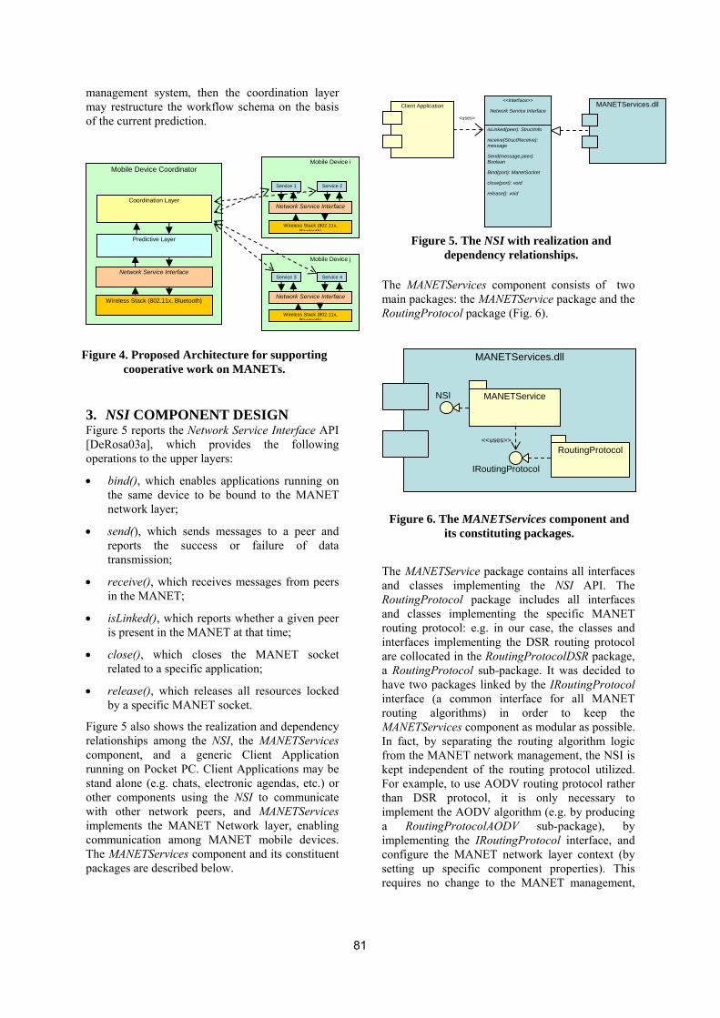
management system, then the coordination layer may restructure the workflow schema on the basis of the current prediction.
The MANETServices component consists of two main packages: the MANETService package and the RoutingProtocol package (Fig. 6).
Client Application MANETServices.dll <<interface>>
Network Service Interface
isLinked(peer): StructInfo
receive(StructReceive): message
Send(message,peer): Boolean
Bind(port): ManetSocket
close(port): void
release(): void
<uses>
Mobile Device j
Service 3 Service 4
Network Service Interface
Wireless Stack (802.11x, Bluetooth)
Mobile Device i
Service 1 Service 2
Network Service Interface
Wireless Stack (802.11x, Bluetooth)
Mobile Device Coordinator
Wireless Stack (802.11x, Bluetooth)
Network Service Interface
Coordination Layer
Predictive Layer
MANETServices.dll
Figure 4. Proposed Architecture for supportingcooperative work on MANETs.
3. NSI COMPONENT DESIGN Figure 5 reports the Network Service Interface API [DeRosa03a], which provides the following operations to the upper layers:
• bind(), which enables applications running on the same device to be bound to the MANET network layer;
• send(), which sends messages to a peer and reports the success or failure of data transmission;
• receive(), which receives messages from peers in the MANET;
• isLinked(), which reports whether a given peer is present in the MANET at that time;
• close(), which closes the MANET socket related to a specific application;
• release(), which releases all resources locked by a specific MANET socket.
Figure 5 also shows the realization and dependency relationships among the NSI, the MANETServices component, and a generic Client Application running on Pocket PC. Client Applications may be stand alone (e.g. chats, electronic agendas, etc.) or other components using the NSI to communicate with other network peers, and MANETServices implements the MANET Network layer, enabling communication among MANET mobile devices. The MANETServices component and its constituent packages are described below.
The and Routand routiinterare ca RohaveinterroutiMANIn fafromkept For ethan impla implconfsettinrequ
81
Figure 5. The NSI with realization and dependency relationships.
MANETService
RoutingProtocol <<uses>>
IRoutingProtocol
NSI
Figure 6. The MANETServices component and
its constituting packages.
MANETService package contains all interfaces classes implementing the NSI API. The
ingProtocol package includes all interfaces classes implementing the specific MANET ng protocol: e.g. in our case, the classes and faces implementing the DSR routing protocol ollocated in the RoutingProtocolDSR package, utingProtocol sub-package. It was decided to two packages linked by the IRoutingProtocol face (a common interface for all MANET ng algorithms) in order to keep the ETServices component as modular as possible. ct, by separating the routing algorithm logic the MANET network management, the NSI is independent of the routing protocol utilized. xample, to use AODV routing protocol rather DSR protocol, it is only necessary to
ement the AODV algorithm (e.g. by producing RoutingProtocolAODV sub-package), by ementing the IRoutingProtocol interface, and igure the MANET network layer context (by g up specific component properties). This
ires no change to the MANET management,

nor, in consequence, to the client application source code. This is a typical application of the “Strategy” pattern presented in [Gamma94a], in which ConcreteStrategies are the classes realizing the MANET routing protocols (see Figure 7).
MThpaIn(se
AsormaMrumaro
tables if any, etc. At run time there is therefore only one MANETManager class instance which has strict control over how and when client applications access the NSI. The unique manager object maintains a list of opened MANETSocket objects for each application, which obtain shared information through synchronized methods. For these reasons we adopted the Singleton pattern [Gamma94a] for the MANET communication layer as a design solution, where the singleton class is our MANETManager class (Figure 9).
<<interface>>
IRoutingProtocol getRouteFor(peer): Route
getAllNetUsers(): array
getNeighbours(): array
DSR
getRouteFor(peer): Route
getAllNetUsers(): array
getNeighbours(): array
AODV
getRouteFor(peer): Route
getAllNetUsers(): array
getNeighbours(): array Client Application
MANETManager
static getMANETManager()
bind(int port): MANETSocket
close(int port): void
release(): void
<<uses>>
MANETSocket
send(Message message): bool
isLinked(Peer peer): bool
receive(): Message
1 0..
<<uses>>
Figure 7. The Strategy pattern for MANETrouting algorithms.ANETService Package e main classes constituting the MANETService ckage and realizing the Network Service terface are MANETManager and MANETSocket e Figure 8).
w an
ANnnn
uti
4. NSI IMPLEMENTATION AND TESTING We implemented NSI as a .NET Compact Framework component, coded in C#, to be run on both PDAs, with the Windows Mobile operating system, and laptops (or any desktop) with the Windows operating system desktop version. The Dynamic Source Routing protocol [Johnson94a], specifically optimized for route caching [Vaidya04a], was implemented to support inter-device communication. To our knowledge, this is the first effective implementation of a MANET routing protocol for PDAs (which are mainly Windows-based), as current research and the available commercial tools are targeted only at supporting laptops running Linux.
<<interface>>
Network Service Interface
MANETSocket MANETManager
NSIRealization
0..* 1
Figure 8. Main Classes constituting theMANETService package.ith a file system manager, a window manager, printer spooler, the MANETManager class ages and controls concurrent access to the
ET network layer of client applications ing on the same mobile device, specifically aging access to shared information of the ng protocol used, e.g. neighbor list, routing
82
Figure 9. The Singleton pattern for MANET
connection manager.
For our experiments we deployed the NSI component on several kinds of PDA devices, with:
• IPAQ 5550 and IPAQ 5540 with 450 MHz processors and 128 MB RAM,
and on:
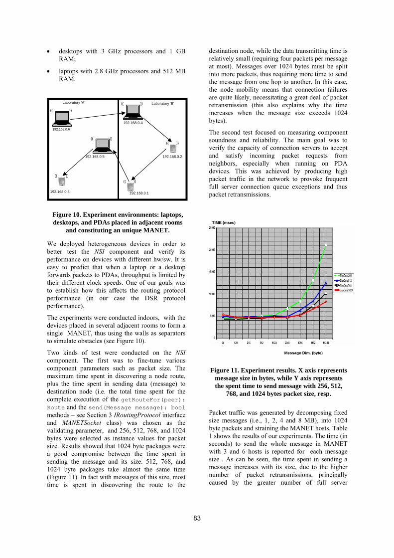
• desktops with 3 GHz processors and 1 GB RAM;
• laptops with 2.8 GHz processors and 512 MB RAM.
Wbpefttpp
Tdst
TccmpdcRmavbsas1(t
destination node, while the data transmitting time is relatively small (requiring four packets per message at most). Messages over 1024 bytes must be split into more packets, thus requiring more time to send the message from one hop to another. In this case, the node mobility means that connection failures are quite likely, necessitating a great deal of packet retransmission (this also explains why the time increases when the message size exceeds 1024 bytes).
The second test focused on measuring component soundness and reliability. The main goal was to verify the capacity of connection servers to accept and satisfy incoming packet requests from neighbors, especially when running on PDA devices. This was achieved by producing high packet traffic in the network to provoke frequent full server connection queue exceptions and thus packet retransmissions.
(( ))
(( ))))((
))((
))((
))((
Laboratory ‘A’ Laboratory ‘B’
192.168.0.6
192.168.0.4
192.168.0.2 192.168.0.5
192.168.0.3 192.168.0.1
)
Figure 10. Experiment environments: laptops,desktops, and PDAs placed in adjacent rooms
and constituting an unique MANET.
e deployed heterogeneous devices in order to etter test the NSI component and verify its erformance on devices with different hw/sw. It is asy to predict that when a laptop or a desktop orwards packets to PDAs, throughput is limited by heir different clock speeds. One of our goals was o establish how this affects the routing protocol erformance (in our case the DSR protocol erformance).
he experiments were conducted indoors, with the evices placed in several adjacent rooms to form a ingle MANET, thus using the walls as separators o simulate obstacles (see Figure 10).
wo kinds of test were conducted on the NSI omponent. The first was to fine-tune various omponent parameters such as packet size. The aximum time spent in discovering a node route,
lus the time spent in sending data (message) to estination node (i.e. the total time spent for the omplete execution of the getRouteFor(peer): oute and the send(Message message): bool ethods – see Section 3 IRoutingProtocol interface
nd MANETSocket class) was chosen as the alidating parameter, and 256, 512, 768, and 1024 ytes were selected as instance values for packet ize. Results showed that 1024 byte packages were good compromise between the time spent in ending the message and its size. 512, 768, and 024 byte packages take almost the same time Figure 11). In fact with messages of this size, most ime is spent in discovering the route to the
Psb1swsmnc
83
TIME (msec
acket traffic was generatedize messages (i.e., 1, 2, 4yte packets and straining th shows the results of our execonds) to send the wholith 3 and 6 hosts is repo
ize . As can be seen, the essage increases with its
umber of packet retranaused by the greater n
Message Dim. (byte)Figure 11. Experiment results. X axis represents message size in bytes, while Y axis represents the spent time to send message with 256, 512,
768, and 1024 bytes packet size, resp.
by decomposing fixed and 8 MB), into 1024 e MANET hosts. Table periments. The time (in e message in MANET rted for each message time spent in sending a size, due to the higher smissions, principally umber of full server
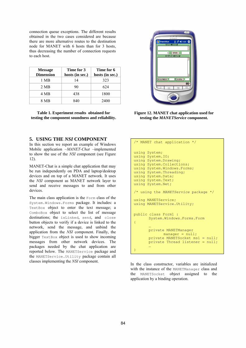
connection queue exceptions. The different results obtained in the two cases considered are because there are more alternative routes to the destination node for MANET with 6 hosts than for 3 hosts, thus decreasing the number of connection requests to each host.
Message
Dimension Time for 3
hosts (in sec.) Time for 6
hosts (in sec.) 1 MB 14 323 2 MB 90 624
4 MB 438 1800
8 MB 840 2400
5. USING THE NSI COMPONENT In this section we report an example of Windows Mobile application –MANET-Chat –implemented to show the use of the NSI component (see Figure 12).
MANET-Chat is a simple chat application that may be run independently on PDA and laptop/desktop devices and on top of a MANET network. It uses the NSI component as MANET network layer to send and receive messages to and from other devices.
The main class application is the Form class of the System.Windows.Forms package. It includes: a TextBox object to enter the text message; a ComboBox object to select the list of message destinations; the isLinked, send, and close button objects to verify if a device is linked to the network, send the message, and unbind the application from the NSI component. Finally, the bigger TextBox object is used to show incoming messages from other network devices. The packages needed by the chat application are reported below. The MANETService package and the MANETService.Utility package contain all classes implementing the NSI component.
Table 1. Experiment results obtained for testing the component soundness and reliability.
Iwta
84
Figure 12. MANET chat application used for testing the MANETService component.
n the class constructor, variables are initialized ith the instance of the MANETManager class and
he MANETSocket object assigned to the pplication by a binding operation.
/* MANET chat application */
using System; using System.IO; using System.Drawing; using System.Collections; using System.Windows.Forms; using System.Threading; using System.Data; using System.Text; using System.Net; /* using the MANETService package */ using MANETService; using MANETService.Utility; public class Form1 : System.Windows.Forms.Form { … private MANETManager manager = null; private MANETSocket ms1 = null; private Thread listener = null; … }
The send, isLinked, and close application buttons use the NSI component’s send, isLinked, and close methods. The receive method is called by a thread object listening on a specific port.
6. CONCLUSION AND FUTURE WORK In this paper we presented the design and a possible implementation of the Network Service Interface layer as a .NET Compact Framework component, coded in C#, to be run on PDAs with the Windows Mobile operating system; we chose Dynamic Source Routing as the routing protocol supporting inter-device communication.
The layer prototype is available at: http://www.dis.uniroma1.it/pub/~mecella/projects/MobiDIS/.
We reported a set of NSI component tests and their results. Finally, we described an example of Windows Mobile application –MANET-Chat – in order to show the use of the NSI component.
Future work will involve the development of the predictive layer on top of the NSI component in the .NET environment, using the probabilistic technique presented in [DeRosa05a].
public Form1() { InitializeComponent(); /* Getting the unique MANETManager instance */ manager = MANETManager.getMANETManager(); /* Binding application on port 50 */ ms1 = manager.bind(50); listener = new Thread(new ThreadStart(this)); listener.Start(); … }
/* Using the NSI send() method */ public void send(){ this.textBox3.Text = ""; string nameDest = this.comboBox1.Text; string message = this.textBox1.Text; byte[] message_b= Encoding.UTF8.GetBytes(message); Boolean boo = ms1.send(nameDest,50,message_b); this.textBox3.Text = boo.ToString(); }// End the send method … /* Using the NSI receive() method */ public void receive(){ … StructReceive sr = new StructReceive(50); StructReceive result = null; while(breaking) {
result = ms1.receive(sr);
if(result != null){ string[] message = result.getMessage(); … break; } } … }// End the receive method … /* Using the isLinked() method */ public void isLinked(){ string nameDest = this.comboBox1.Text; Boolean bo = ms1.isLinked(nameDest); textBox5.Text = bo.ToString(); } /* The close method to unbind the MANET chat application */ public void close(object sender, System.EventArgs e) { MANETManager.close(50); … MANETManager.release(); … }
85

7. ADDITIONAL AUTHORS Fiammetta Pascucci and Piergiorgio Faraglia, undergraduates of the Faculty of Computer Engineering, University of Rome “La Sapienza”.
8. REFERENCES [Agrawal03a] Agrawal, D. P., and Zeng, Q. A. ,
“Introduction to Wireless and Mobile Systems”, Thomson Brooks/Cole, 2003.
[Grudin04a] Grudin, J., “Computer-Supported Cooperative Work: History and Focus”, IEEE Computer 27(5): 19-26, 1994.
[Vaidya04a] Vaidya, N. H., “Mobile Ad Hoc Networks: Routing, MAC and Transport Issues” Tutorial on Mobile Ad Hoc Networks, http://www.crhc.uiuc.edu/nhv, University of Illinois at Urbana-Champaign, USA, July 2004.
[DeRosa03a] De Rosa, F., Di Martino, V., Paglione, L., and Mecella, M., “Mobile Adaptive Information Systems on MANET: What We Need as Basic Layer?”. In Proceedings of the 1st IEEE Workshop on Multichannel and Mobile Information Systems (MMIS’03), Rome, Italy, 2003.
[DeRosa05a] De Rosa, F., Malizia, A., and Mecella, M., “Disconnection Prediction in Mobile Ad hoc Networks for Supporting Cooperative Work”. IEEE Pervasive Computing, 2005, to appear.
[Gamma94a] Gamma, E., Helm, R., Johnson,R, and Vlissides, J., “Design Patterns: Elements of Reusable Object-Oriented Software”. Addison-Wesley Professional Computing Series, 1994.
[Johnson94a] Johnson, D., and Maltz, D. A., “Dynamic source routing in ad hoc wireless networks," in Mobile Computing (T. Imielinski and H. Korth, eds.), Kluwere Academic Publishers, 1994.
86
Porting the .NET Compact Framework to Symbian Phones – A Feasibility Assessment
Alain Gefflaut, Friedrich van Megen, Frank Siegemund, Robert Sugar
European Microsoft Innovation Center
Ritterstr. 23
D-52072 Aachen, Germany
{alaingef|fmegen|franksie|rsugar}@microsoft.com
ABSTRACT As a result of the increasing availability and processing capacity offered by portable devices, it is important for software providers to offer mobile services that seamlessly interoperate with business applications. However, currently there is still a considerable technology gap between building .NET applications on PC-like systems and programming mobile services on mid-range portable devices, a large number of which run the Symbian operating system. As Microsoft has built its .NET Compact Framework Common Language Runtime (CLR) for high-end mobile devices, it would be desirable to bring a reasonable subset of this technology to mid-range smartphone devices as well. Such a platform for executing .NET applications on Symbian-enabled smartphones has then the potential (1) to considerably facilitate the migration of .NET applications to portable devices and (2) to increase the interoperability between software running on stationary systems and mobile services. In this paper, we present an initial feasibility assessment for porting the .NET Compact Framework to Symbian smartphones, and analyze how the unique characteristics of the Symbian operating system affect the portability of the .NET Compact Framework. Based on our experiences in porting parts of the .NET Compact Framework to Symbian, we illustrate code portability between different platforms and provide a preliminary performance analysis of the .NET Compact Framework compared to Java.
Keywords .Net Compact Framework – Symbian – Mobile Services – Smartphones – Software Migration.
1. INTRODUCTION During the last two decades, mobile phones have become almost ubiquitous. As a result of this development, it is increasingly important for software providers to offer mobile services that seamlessly interoperate with their business applications in order to improve customer satisfaction and service availability. The .NET Framework has been a popular platform for creating such applications and services both on stationary computers and Windows CE-based PDAs. However, a large number of today’s
smartphones are currently based on the Symbian operating system, for which applications are either developed in Symbian C++ or Java. According to a recent study [Gar04], 80% of all smartphones shipped in the 3rd quarter of 2004 were Symbian phones. Hence, for the next couple of years Symbian smartphones are likely to remain an important platform for implementing mobile services.
As a consequence, it would be beneficial if .NET applications could also be executed on Symbian-enabled devices. .NET developers could then reuse their code for mobile services instead of reimplementing their applications from the ground up using C++ or Java. Reimplementation can be especially cumbersome since commonly used CLR/.NET features may not be present in different programming models (e.g. floating point support is absent in some J2ME profiles, SOAP Web Services support may be missing, XML and graphics programming model might differ). These issues mean that direct code reuse is not possible, which results in
Permission to make digital or hard copies of all or part of this work for personal or classroom use is granted without fee provided that copies are not made or distributed for profit or commercial advantage and that copies bear this notice and the full citation on the first page. To copy otherwise, or republish, to post on servers or to redistribute to lists, requires prior specific permission and/or a fee.
.NET Technologies’2005 conference proceedings, ISBN 7/,75832,/0,0 Copyright UNION Agency – Science Press, Plzen, Czech Republic
87

increased costs and is likely to introduce new program errors. Having a Common Language Runtime (CLR) running on Symbian smartphones also implies that developers could implement applications for this platform using the same programming environment and tools offered for the .NET Framework. We would like to argue that such an approach has the potential to considerably simplify the migration of .NET applications to mobile devices and makes it easier for software developers to design mobile services that interoperate with stationary .NET applications.
In this paper, we investigate whether it is feasible to port the .NET Compact Framework to Symbian, and report on our preliminary experiences in porting parts of the .NET Compact Framework to this platform. The paper also contains an analysis of specific characteristics of Symbian and describes how the internals of the Symbian operating system affect the portability of the .NET Compact Framework. Furthermore, we provide a preliminary performance analysis of executing applications for Symbian smartphones by means of the Common Language Runtime (CLR).
The remainder of this paper is structured as follows: The following section summarizes related work. Sect. 3 provides an overview of the .NET Compact Framework architecture. Sect. 4 reports on our experiences in porting parts of the .NET Compact Framework to Symbian phones and shows how we dealt with the specific demands of the Symbian operating system. In Sect. 5 we evaluate our implementation in comparison to Java. Sect. 6 gives an outlook on future work, while Sect. 7 concludes the paper.
2. RELATED WORK The number of programming languages targeting the Common Language Infrastructure (CLI) has been steadily increasing over the years. Besides the variety of currently supported programming languages, however, CLI run-time technologies have also become increasingly interesting for simplifying the development process across different platforms and operating systems. Examples for this development are Microsoft’s Rotor and 3rd party Mono and DotGNU implementations of the CLI [Rotor,Mono,DotGNU]. The last years have therefore shown a shift from using CLI technologies for language integration on a single platform to improving the development of applications across different platforms and operating systems. As the CLI has been accepted as an international standard, the development into this direction of cross-platform interoperability of CLI languages is likely to persist.
While there are significant projects that aim at supporting .NET on operating systems such as Unix and MacOS, the major difference in hosting the CLI on the Symbian operating system is that the latter is explicitly targeting resource-restricted mobile devices. Constraints regarding the amount of available memory, computational resources, and restrictions in the functionality provided by the operating system pose therefore new demands on the portability of the .NET Framework. Because of these constraints, this paper focuses on the .NET Compact Framework [NETCF] – which itself was designed for mobile devices and first implemented to run on Windows CE. Because of this, it already considers some of the typical constraints of mobile platforms.
Most Symbian smartphones are shipped with a Java Virtual Machine (JVM) already installed on the phone (J2ME MIDP, the Java 2 Platform Micro Edition Mobile Information Device Platform targets resource-restricted mobile devices such as mobile phones). A .NET Compact Framework implementation for smartphones should therefore be at least comparable to Java implementations with respect to provided functionality and resource consumption. Besides this fact, there are however major differences between Java and .NET that make a direct comparison difficult: (1) Java byte code is often interpreted while the CLR primarily uses Just-in-Time (JIT) compilation. (2) There are international standards for the CLI and C#, while there is no such standard for Java (there is a Java Community Process, though). (3) .NET supports many programming languages – with J# also a flavour of Java. This can make direct comparison difficult because this advantage can imply architectural decisions affecting the performance of the CLI. (4) The .NET Compact Framework comes with functionality that is not natively supported by J2ME MIDP. However, there are a range of publicly available add-ons and class libraries that support much of this functionality also on this Java platform [J2MEWeb].
Rashid et al. [RTCE04] compare the performance of native Symbian code with interpreted Java applications, and Raghavan et al. [RSL04] reports on a model-based performance evaluation of applications on mobile devices. In the scope of our work, test suites provided by IBM [IBMBenchmarks], covering basic features such as method calls, thread creation, and data access, were used to carry out performance comparisons.
There are several papers (e.g., [Opera] and [Helix]) dealing with some of the obstacles that arise when porting applications to the Symbian operating system. Some of the described approaches are also applicable
88
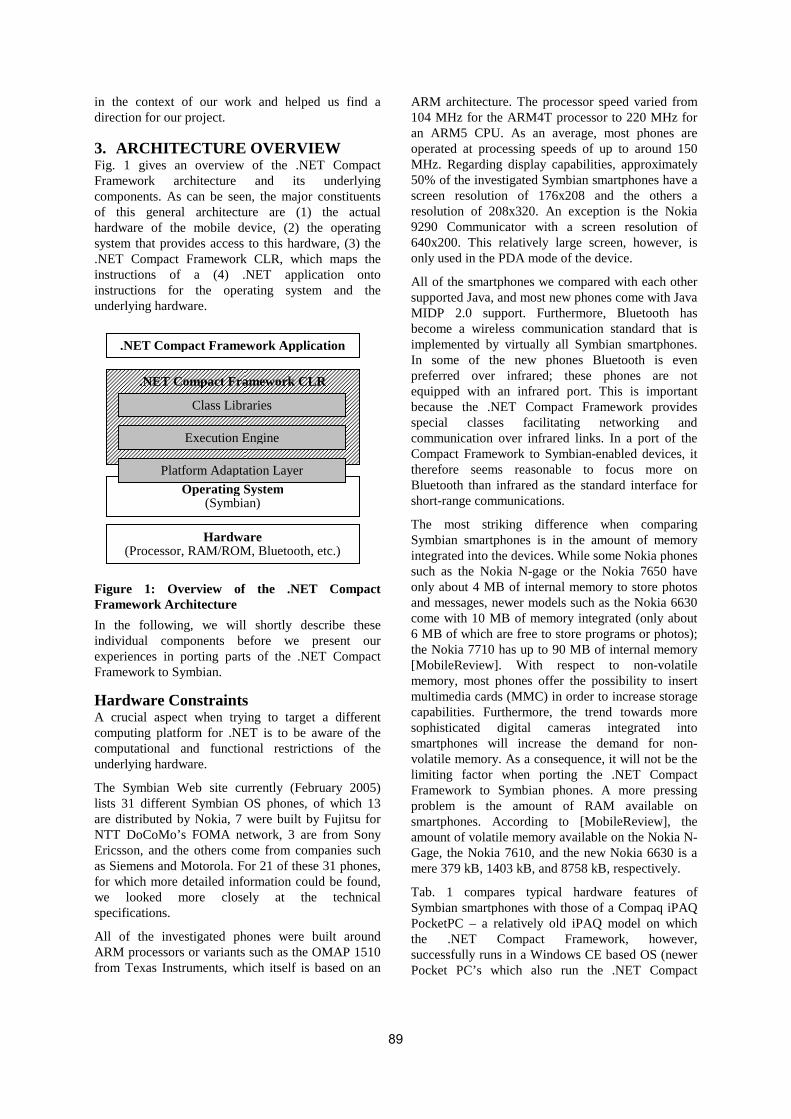
in the context of our work and helped us find a direction for our project.
3. ARCHITECTURE OVERVIEW Fig. 1 gives an overview of the .NET Compact Framework architecture and its underlying components. As can be seen, the major constituents of this general architecture are (1) the actual hardware of the mobile device, (2) the operating system that provides access to this hardware, (3) the .NET Compact Framework CLR, which maps the instructions of a (4) .NET application onto instructions for the operating system and the underlying hardware.
Figure 1: Overview of the .NET Compact Framework Architecture
In the following, we will shortly describe these individual components before we present our experiences in porting parts of the .NET Compact Framework to Symbian.
Hardware Constraints A crucial aspect when trying to target a different computing platform for .NET is to be aware of the computational and functional restrictions of the underlying hardware.
The Symbian Web site currently (February 2005) lists 31 different Symbian OS phones, of which 13 are distributed by Nokia, 7 were built by Fujitsu for NTT DoCoMo’s FOMA network, 3 are from Sony Ericsson, and the others come from companies such as Siemens and Motorola. For 21 of these 31 phones, for which more detailed information could be found, we looked more closely at the technical specifications.
All of the investigated phones were built around ARM processors or variants such as the OMAP 1510 from Texas Instruments, which itself is based on an
ARM architecture. The processor speed varied from 104 MHz for the ARM4T processor to 220 MHz for an ARM5 CPU. As an average, most phones are operated at processing speeds of up to around 150 MHz. Regarding display capabilities, approximately 50% of the investigated Symbian smartphones have a screen resolution of 176x208 and the others a resolution of 208x320. An exception is the Nokia 9290 Communicator with a screen resolution of 640x200. This relatively large screen, however, is only used in the PDA mode of the device.
All of the smartphones we compared with each other supported Java, and most new phones come with Java MIDP 2.0 support. Furthermore, Bluetooth has become a wireless communication standard that is implemented by virtually all Symbian smartphones. In some of the new phones Bluetooth is even preferred over infrared; these phones are not equipped with an infrared port. This is important because the .NET Compact Framework provides special classes facilitating networking and communication over infrared links. In a port of the Compact Framework to Symbian-enabled devices, it therefore seems reasonable to focus more on Bluetooth than infrared as the standard interface for short-range communications.
The most striking difference when comparing Symbian smartphones is in the amount of memory integrated into the devices. While some Nokia phones such as the Nokia N-gage or the Nokia 7650 have only about 4 MB of internal memory to store photos and messages, newer models such as the Nokia 6630 come with 10 MB of memory integrated (only about 6 MB of which are free to store programs or photos); the Nokia 7710 has up to 90 MB of internal memory [MobileReview]. With respect to non-volatile memory, most phones offer the possibility to insert multimedia cards (MMC) in order to increase storage capabilities. Furthermore, the trend towards more sophisticated digital cameras integrated into smartphones will increase the demand for non-volatile memory. As a consequence, it will not be the limiting factor when porting the .NET Compact Framework to Symbian phones. A more pressing problem is the amount of RAM available on smartphones. According to [MobileReview], the amount of volatile memory available on the Nokia N-Gage, the Nokia 7610, and the new Nokia 6630 is a mere 379 kB, 1403 kB, and 8758 kB, respectively.
Tab. 1 compares typical hardware features of Symbian smartphones with those of a Compaq iPAQ PocketPC – a relatively old iPAQ model on which the .NET Compact Framework, however, successfully runs in a Windows CE based OS (newer Pocket PC’s which also run the .NET Compact
Operating System (Symbian)
Hardware (Processor, RAM/ROM, Bluetooth, etc.)
.NET Compact Framework Application
.NET Compact Framework CLR
Class Libraries
Execution Engine
Platform Adaptation Layer
89

Framework have significantly greater resources). As we can see, the most relevant physical difference between the iPAQ and the smartphones is the amount of memory integrated into the devices. Following an exploratory approach, we tried to assess the memory demands of a .NET Compact Framework for smartphones by porting parts of the framework to the Symbian platform (cf. Sect. 5). Considering the other hardware characteristics both platforms are somewhat similar, so that none of the hardware constraints found on smartphones should make it impossible to port the .NET Compact Framework to this platform.
Table 1: Typical hardware characteristics of Symbian smartphones compared to that of an
iPAQ H3650
iPAQ H3650 Smartphones
OS Windows Symbian
Processor 206 MHz Intel StrongARM
up to 220 MHz ARM architecture
Memory 32 MB RAM 16 MB Flash
typ. <<10 MB RAM typ. < 10 MB Flash
Display 240x320 touch screen
176x208 or 208x320 typ. no touch screen
Connect IrDA, Bluetooth Bluetooth, IrDA
Operating System The second layer in our overall architecture (cf. Fig. 1) is made up of the operating system, in our case the Symbian OS. In many respects does the Symbian OS considerably differ from Windows CE, which has been the standard platform for hosting the .NET Compact Framework CLR implementation. These differences affect such elementary features as multitasking, error handling, file access, and networking. They have therefore a significant impact on our goal to port the .NET Compact Framework.
Here are some of the Symbian characteristics that so far caused most of the problems in our project (for a more detailed description of these issues, please refer to Sect. 4):
• A C++ dialect that redefines basic language structures
• No writable global and writable static variables allowed in DLLs
• Extensively used client/server model that, for example, implies constraints for accessing file and networking functions
• Event-driven programming model with a focus on non-preemptive multitasking
• Symbian’s error handling and cleanup model
• Concepts from the Unix/Windows world such as environment variables as well as several file and networking functions are missing
CLR Architecture Overview The .NET Compact Framework CLR is made up of the following main components: (1) class libraries, (2) execution engine, and (3) platform adaptation layer.
The goal of the .NET Compact Framework class libraries is to provide a basic set of classes, interfaces, and value types that constitute the foundation for developing applications in .NET. For example, support for integers, boolean values or strings, functionality for performing I/O, classes for handling exceptions, and methods for collecting information about loaded classes are all included in the class libraries of the .NET Compact Framework.
The execution engine is the core component of the CLR – it provides the fundamental services necessary for carrying out managed code. While the execution engine consists of a large number of individual components, some of its most important parts are: (1) a just-in-time (JIT) compiler (or alternatively an interpreter), (2) a garbage collector, and (3) a class and module loader. The decision whether to use a JIT compiler or to immediately carry out generated instructions in an interpreter depends on the resource constraints of a given platform. Our preliminary port is based on a JIT compiler, not an interpreter.
Because the design of the .NET Compact Framework anticipated operating system portability, access to core operating services occurs through a PAL layer. The main responsibility of the platform adaptation layer (PAL) is to map calls from the execution engine to functions provided by the underlying host operating system. In other words, the PAL serves as the main mediator between the operating system (Symbian OS in our case) and the CLR. As a result of the architectural design of the .NET Framework, the PAL is the core component that needs to be reimplemented when porting the .NET Compact Framework to Symbian OS. To illustrate the responsibility of the PAL, let us consider the example of a simple Web request. Using .NET class libraries, the code for retrieving a Web page in C# could look like this:
WebRequest req; WebResponse resp; 4: req = WebRequest.Create( “http://www.microsoft.com”); 5: resp = req.GetResponse();
Classes such as WebRequest and WebResponse belong to System.Net and are therefore part of the
90

class libraries provided by the .NET Compact Framework. The method calls in lines 4 and 5 of the above code result internally in a number of function calls to the underlying operating system. First, the URL “http://www.microsoft.com” must be internally resolved into a corresponding IP address. Afterwards, a timer is created with a callback function that is executed when the Web page is not retrieved in a certain time frame. Finally, a TCP socket must be created and configured that is used to send a request to and retrieve data from the remote Web server. The implementation of the class libraries in the .NET framework thereby assumes the existence of certain hooks for handling timers and dealing with sockets on the operating system layer. The PAL implements these function hooks based on the capabilities of the underlying operating system. In case of Windows CE, these mappings to function calls of the operating system are often straightforward. However, with Symbian it can be much more complicated to find appropriate mechanisms to implement the desired semantics.
4. PORTING THE .NET COMPACT FRAMEWORK In this section, we describe our port of selected components of the .NET Compact Framework to Symbian-enabled mobile devices. Again, we would like to point out that our work focuses on evaluating whether it is feasible to port the .NET Compact Framework to Symbian phones. As a result, simple solutions were often preferred over more complex approaches in order to get a simple version of the Framework working as soon as possible.
In this section, we attempt to analyze the characteristics of the Symbian operating system that caused most of the problems in our project, and propose solutions for dealing with these issues.
Current Status The preliminary port presented in this paper is based on the Microsoft .NET Compact Framework implementation version 1 for Windows CE. Currently, it is possible to execute basic console-based .NET applications on two Series 60 phones that are based on the Symbian OS: Phone A (OS v6.1 , 3 MB available memory, and a 104 MHz processor) and Phone B (OS v8.0a, 10MB of available memory, and a 220 MHz processor). Furthermore, we support file access and simple networking. To achieve that, work has not only been done on several Platform Adaptation Layer (PAL) modules such as threading, event handling, console output, file access, and networking, but also on the surrounding components that are used to load .NET DLLs and to start .NET applications.
C++ Dialect The flavor of C++ used to implement native Symbian applications caused several problems in our project. In particular, Symbian C++ introduces some peculiar language features and programming models that were partly introduced because of the limited device capabilities of Symbian smartphones and partly due to historical reasons [Nok04]. Important issues are: (1) different standard data types, (2) a missing libc, (3) a special exception handling mechanism, and (4) a different memory management model.
First, simple types such as int or unsigned long are not recommended by the Symbian Software Development Kit (SDK), so types such as TInt and TUInt32 had to be used instead. The STL (Standard Template Library) is also not supported due to size limitations.
Second, as a libc is not supported by Symbian, a basic implementation had to be attached to our project containing memory management (like memcmp) or C-type string manipulation functions (such as strlen).
Third, the GNU C++ implementation of exception handling was not mature enough at the design time of EPOC (the old name of Symbian), thus the designers employed a more lightweight approach to error handling – the “trap harness” mechanism. A function called User::Leave() corresponds to the throw directive, while the TRAP and TRAPD macros are called instead of catch. Exception objects were also replaced by simple error codes.
Furthermore, as mobile phones are switched on for long periods of time, the ability to reclaim unused heap cells was crucial during the design of Symbian. Therefore, a mechanism called “two-phase-construction” is used during object creation, and a “cleanup stack” structure makes sure that every object created on the heap is destroyed after it has been used.
Writable Global and Writable Static Variables in DLLs The Symbian operating system was built with memory-constraint devices in mind. Therefore, it tries to avoid all unnecessary allocations or wastage of main memory. To prevent allocation of memory for writable static data in DLLs, which would have to be allocated for each application, and to enable eXecution In Place (XIP), DLLs that are stored in ROM are not copied to RAM. As a consequence, the programming environment does not support writable static or global data because the segment containing these values in the DLL is not writable.
If this requirement is not a major issue when writing new applications, it becomes a major problem when
91

porting applications that have been designed to run on operating systems supporting writable static data. This is the case for the original Microsoft .NET Compact Framework, which usually runs on top of Windows class operating systems. Two strategies can be envisaged to solve this problem. First, rewriting the libraries was ruled out as a viable solution since the number of writable static data was too large to enable a manual rewrite of the libraries. The second strategy, which is the one we followed as a way to get a test version of the .NET Framework working as soon as possible, consists in loading in RAM all DLLs used by the .NET Compact Framework application. To reach this goal, we designed and wrote a specific loader. Starting the Framework is then realized by calling the loader. The loader is in charge of downloading in RAM the image of the .NET Compact Framework binary, as well as all libraries that it needs (including the writable data section). The loader also performs the necessary relocation in order to prepare the execution. Once relocation is done, the loader identifies the entry point defined in the .NET Compact Framework binary and jumps to its location. Although this solution works, it is far from optimal since it can result in a possibly high memory footprint. While this is not a problem in our feasibility assessment, this issue would have to be addressed in a real, complete port of the .NET Compact Framework to Symbian.
Starting .NET Applications When a .NET application – which is usually generated using a development environment and a compiler on a Windows-based PC system – is to be executed on a Symbian phone, it must be assigned to our .NET Compact Framework implementation for execution. As .NET compilers generate files in the standard .NET portable executable file format, it is possible to distinguish any .NET application from native Symbian applications. Luckily, the Symbian OS provides the concept of so called Recognizers, which are used to assign certain file types to selected applications. For example, HTML files can be associated with a Web browser, PDF files with an Acrobat reader, etc. As this association can be based on more that just the file extension and allows us to analyze the file to be executed, we use a special Recognizer for starting .NET applications.
Dealing with Symbian’s Client/Server Framework The Symbian OS introduces a range of servers to deal with system resources on behalf of different clients. Examples for such servers are the file server, the socket server, and the window server; servers are usually located in a different process than the clients that want to access their services. The problem with
Symbian’s client/server framework from the perspective of the .NET Compact Framework is that only the client thread that creates resources for interacting with a server can use and destroy them. This has some implications for a port of the .NET Framework, and especially the Platform Adaptation Layer (PAL). Imagine that there is a .NET application consisting of two threads that both want to access a file. In this scenario, the PAL would be responsible for mapping the file access to corresponding operating system functions. For example, there would be a function like PALFile_Open() that sends a request to the Symbian file server to open a file. However, since both .NET threads – which are both mapped to Symbian threads in our implementation – might want to open a file, this is not possible because only the client thread that created the connection to the file server can do that. To solve this problem, we introduced a mediator thread that handles all communication with the file server. Symbian OS threads that represent threads in .NET then interact with this additional thread in order to access files. For the PAL implementation, this means that PALFile_Open() does not interact with the file server directly, but instead issues a request to the intermediary thread communicating with the file server. A similar mechanism is deployed to handle networking and console access.
Dealing with Symbian’s Focus on Cooperative Multitasking In the desktop domain, pre-emptive multitasking replaced cooperative multitasking years ago when resources became cheaper and PC-like systems much more computationally powerful. Furthermore, using pre-emptive multitasking for different computations that need to be carried out concurrently is much easier from a programmer’s point of view than having to deal with the burden to split a long-running task into subtasks in order to keep up responsiveness. However, although the Symbian operating system supports pre-emptive multitasking, switching between different pre-emptive threads is considered very expensive and programmers are strongly encouraged to use cooperative multitasking instead [Nok04, Har03]. To support programmers in handling cooperative multitasking, Symbian introduced the concept of Active Objects as a programming paradigm. Together with a so-called Active Scheduler, Active Objects are supposed to facilitate the programming of non-preemptive concurrent tasks.
However, cooperative multitasking using Active Objects has still the disadvantage that if there is a long-running calculation, it only will give control to another task if it is finished. As this might severely
92

reduce the responsiveness of a user interface, for example, books on Symbian programming [Har03, Nok04] strongly suggests manually splitting long-running tasks into smaller subtasks that can faster pass on control to other subtasks, thereby improving the overall responsiveness of the system. This, however, does not map well with the notion of threads in .NET because threads in .NET are generally viewed as being preemptively scheduled. To deal with this issue in a port of the .NET Compact Framework there are several theoretical solutions:
(1) If there is a thread in .NET, it is possible to generate a pre-emptively scheduled thread in the Symbian operating system and accept the effect on system performance this does imply. (2) When the execution engine requests a new thread to be created for a thread in a .NET application, a new Active Object could be created that handles the associated task. However, this would mean that we would need a mechanism to automatically find a location in the code where this active object can pass on control to a different task. Finding a place where this can be done requires at least the help from the JIT compiler or special statements in the .NET code that would have to be used by a programmer. (3) Another important issue with threads is that Symbian’s client/server model (see previous subsection) forces us to introduce preemptively scheduled threads on the operating system layer to sequentialize access to servers (the file server, for example). In order to reduce the number of low-level Symbian threads, it is possible to use a single thread for all different servers. The downside of this, however, is that a .NET thread that wants to output a string on the console might need to wait for a different .NET thread that wants to do file access. Whether this can be accepted depends mainly on the concrete .NET application. In the current state of our port, .NET threads are directly mapped to pre-emptively scheduled threads on the Symbian operating system layer.
5. EVALUATION The purpose of this section is to estimate the performance of a .NET Compact Framework implementation for Symbian smartphones in comparison to other runtime environments where intermediate code is executed by a just-in-time compiler or an interpreter. To achieve this goal, we compare the time necessary to execute .NET code on our platform with the time needed to execute Java code on a Symbian smartphone. As it would be too complex to compare and difficult to interpret the runtime characteristics of complete applications written for .NET and Java – due to the different algorithms and optimizations Java and .NET runtimes might use – our approach is instead based on micro-
benchmarking. Micro-benchmarks are simple programs (usually loops) targeting a single functionality such as memory allocation or thread synchronization. Because of the simplicity of the underlying programs, porting the benchmarks to both Java MIDP and .NET is relatively simple. This also assures that a comparison based on these benchmarks stays fair.
In order to carry out the evaluation, we chose a suite of micro-benchmarks originally written by IBM to measure the performance of simple Java operations in a standard Java Virtual Machine (JVM) environment [IBMBenchmarks]. These benchmarks originally targeted the desktop versions of Java and thus are using APIs that are not available on a Symbian smartphone. Therefore, we selected relevant tests from this benchmarking suite and adapted them such that they could be executed by the JVMs installed on our Symbian smartphones. As a result, benchmarks for the reflection interface of Java were omitted as well as tests targeting file access functions (file access is not supported on the smartphone JVMs used in our tests). Additionally, we also had to drop any benchmark using Java functionality not available to .NET applications.
The other major change in the benchmarks dealt with timing issues. Instead of dynamically calculating the number of iterations of a test, we hard-coded the number of iterations for each benchmark based on the duration of a test. This was done because it simplifies porting of the test framework to C#, and because it ensures that all tests are carried out the same amount of times on different devices. In general, faster tests run more often than more time-consuming tests. For the above reasons, test results measured with the selected benchmark suite on another hardware platform cannot be directly compared to the results presented in this paper.
Porting the Benchmarks to C# In a second step, we ported the selected set of micro-benchmarks to the .NET Compact Framework using C#. Because Java is quite similar to C#, porting the micro-benchmarks required mainly small syntactic modifications. For example, the C# language keeps a different set of reserved identifiers, thus, variables named internal or object had to be renamed. Besides syntactic modifications, a few discrepancies between Java and C# forced us to modify the code.
Unlike Java, for example, C# does not support the synchronized tag for methods or classes. For tests that required synchronized method calls, we removed the synchronized tag and added a lock(this) as the first statement of the method. The lock statement in C# is used to acquire the monitor associated to an instance of a class, thereby
93

preventing anybody else from calling a method of this object. As a result, this statement emulates the behavior of the synchronized tag of Java.
Another, slightly more complex modification in the benchmarks was necessary because there is no simple alternative to the Thread.Join() statement in the .NET Compact Framework. This is a difference w.r.t. the original .NET Framework, but in the Compact Framework, it is difficult to ask a thread to wait for the completion of another thread. To handle this problem, we rewrote the original tests such that explicitly generated events were used for signaling.
Micro-Benchmarks Description The first micro-benchmark in our evaluation (cf. Tab. 2) measures memory read latency by reading the elements of an array. The second micro-benchmark measures the efficiency of calling a single method. The test distinguishes between calling a plain and a synchronized method. The third micro-benchmark deals with thread creation. This test sequentially creates threads and waits for them to start. Since the Symbian documentation in many places warns against the overhead involved when creating threads we were especially curious how well our implementation behaves compared to the Java thread implementation. The fourth micro-benchmark measures the time necessary to create new objects and the overhead caused by inheritance. In particular, it tests the creation of small objects derived over two generations compared to the creation of large objects that also inherit from a baseclass over two generations. This test also illustrates the performance of the memory subsystem and to some extend of the garbage collector. The fifth micro-benchmark measures the performance of comparing strings. The last three tests concentrate on measuring the performance of general array handling operations (e.g., initialization and copying). Both Java and C# provide support for a system-level array copy function a programmer should use for performance reasons. The CopyArray test therefore has two versions, one using the system-level function, the other using a naive copy of the array using a loop. While this might result in a performance penalty for a runtime that interprets code, we do not expect a big performance hit when code is generated by a JIT compiler. Similarly, the InitArray and SumArray micro-benchmarks provide two versions, one using a simple loop, the other using unrolling to limit the cost of the loop overhead.
Results Analysis Tab. 2 shows the results obtained by executing the described tests on different platforms and execution environments. For the analysis of the results, the
reader should keep in mind that the .NET tests for Symbian smartphones were carried out on a preliminary port of the .NET Compact Framework.
The first column of Tab. 2 shows the name of the micro-benchmark. The second lists the parameters used to run the micro-benchmark (starting with the number of iterations). Columns three and four show the results, in milliseconds, of the Java micro-benchmarks when executing them on the JVMs that were already installed on the smartphones used for our experiments (cf. Sect. 4). The next three columns show the results when carrying out the benchmarks in a .NET Compact Framework runtime. As can be seen in the table, we have used our port on Phone A and Phone B (cf Sect. 4) for the tests and compared these results with a standard .NET Compact Framework running on a regular PDA (a T-Mobile MDA II running PocketPC 2003 has been used for this experiment). Although not directly comparable, the results obtained with the PDA are useful to find out whether performance differences between Java and .NET are a problem of our PAL implementation or shared between .NET runtimes on different platforms.
As a general result, the speed of our initial port of the .NET Compact Framework is comparable with the corresponding Java implementation on Phone B and sometimes significantly faster on Phone A. A likely reason for this is that the JVM on Phone A seems to use an interpreter, while Phone B comes with a JIT. In two occasions, however, our port of the .NET Compact Framework is much slower than the Java runtime on the same device. These correspond to tests calling synchronizes methods (we are 4.8 times slower on Phone A) and spawning threads (we are 52 times slower on Phone A).
In case of synchronized methods, the Java implementation of a synchronized method call takes twice as long as calling a method that is not synchronized. It is remarkable, however, that this is much faster than the time needed in our port, where calling locked method is 157 times slower than an unsynchronized method call on Phone A. We expected calls to a synchronized method to be slightly slower compared to the unsynchronized version. Furthermore, since there is no real concurrency involved (as only one thread in this test calls the functions), we did not expect a major difference. Our first assumption was that our implementation of the corresponding PAL functions were responsible for the poor performance.
94

Table 2: Time for running benchmarks (in ms) Java .NET Compact Framework
Test Parameter Phone A Phone B Phone A Phone B PDA
1. MemReadLatency #1000000, 4, 512 1578 141 219 110 122
#1000000, 8, 256 1547 125 219 109 121
2. Method Calling #1000000, internal, sync 4094 579 19703 32390 12843
#1000000, internal, nosync 2719 203 125 62 330
#1000000, external, nosync 2703 219 172 79 394
3. Spawn Threads #1000, <> 422 1437 21937 15062 2579
4. AllObjectConstruct #10000, small, assign, 3 219 31 63 94 61
#10000, large, assign, 3 1125 250 ENOMEM 219 103
5. StringCompare #10000, 128 2500 328 531 250 217
#10000, 512 9187 1157 2047 984 854
6. CopyArray #10000, 1024, simple 3890 328 250 375 389
#10000, 1024, system 203 250 531 687 69
7. InitArray #10000, 1024, unrolled 1547 250 31 234 166
#10000, 1024, simple 3438 235 16 250 271
8. SumArray #1000, 512,simple 187 16 531 0 15
#1000, 512,unrolled 94 16 2047 0 12
Comparing this to the tests running on the PDA, however, revealed that the real reason might partially reside in the implementation of the Compact Framework itself. This is because even on the PDA locked code runs 39 times slower than a function not using the lock statement (cf. previous subsection). Spawning a thread is also considerably slower in our Symbian .NET Compact Framework implementation than in the Java implementation.
Right now, we are not sure if this is due to a bad implementation in our PAL layer or to the use of different synchronization primitives in our adaptations of the micro-benchmarks. The result for the same test on the PDA seems to indicate that it is a problem of our implementation on Symbian, and we are currently in the process of identifying the underlying problem.
As can be seen in Tab. 2, one of the tests (AllObjectConstruct with large objects) failed with an out-of-memory error on Phone A. A possible explanation for this problem is that the garbage collector was not able to reclaim memory as quickly as the test requested new objects to be created. To confirm this theory, we modified the test to manually call the garbage collector during the test. This solved the problem, but did not allow us to report useful results since the reported time to execute the benchmark included the time to run the garbage collector. Solving this issue is a work item for us that we will investigate in the scope of our project.
6. FUTURE WORK Security So far, we have not explicitly dealt with security in our project, but there are a number of security features that could be addressed in the future. These features could be divided into managed code security and the .NET Framework security.
Managed code security generally follows the guidelines of the .NET Compact Framework, which currently allows full access to resources through the P/Invoke mechanism (which allows for calling functions of the underlying OS). Later releases of the .NET Compact Framework will support security policies, custom permission sets, imperative and declarative security checks [MSDNSecurity].
Our .NET Compact Framework runtime itself is a Symbian application, thus special attention needs to be placed on testing the implementation against possible exploits – especially the PAL layer, which has access to core OS features.
Porting the GUI Symbian allows access to the GUI on several layers. The OS itself provides a common graphics server that provides the main window, basic drawing functions, and event handling mechanisms. Direct screen access is also possible. On top of that there are several phone-specific graphic libraries, the most common being the AVKON library built for Series 60 phones.
95

Three distinct approaches were identified that could be followed in implementing the GUI:
1. Using basic drawing primitives to adapt an existing portable graphics library to Symbian smartphones. This approach would be the easiest to implement, but it would probably result in a high memory footprint and a slow performance of the UI subsystem. The look-and-feel would also be different from native Symbian applications.
2. Mapping .NET user interface calls to AVKON. This would be the most convenient solution, but there are significant differences between the two APIs. Major problems include the creation of resource files that the Symbian GUI framework relies on and several threading issues that prevent multiple threads to access the same control or have a parent-child window relationship.
3. Providing access for the AVKON GUI: This would place the burden of dealing with a device-specific library on the .NET developer, but proxy objects and helper functions could assist her during the process.
7. CONCLUSION This paper evaluated the feasibility of porting the .NET Compact Framework to Symbian smartphones. Our analysis shows that the specifics of the Symbian OS and the resource constraints of today’s smartphones make porting difficult but not impossible. Carrying out a serious port of the .NET framework, however, would require a considerable amount of manpower in order to appropriately react to the constraints of the Symbian platform. Our comparison with Java showed that .NET programs executed on smartphones would have similar performance characteristics. This is a very promising result and speaks in favour of the overall design of the .NET Compact Framework for resource-constraint devices.
8. ACKNOWLEDGMENTS We would like to thank Gerd Rausch for helping us with the implementation. We thank Wolfgang Manousek, Mark Gilbert, and Ivo Salmre for all the competent comments regarding the .NET Compact Framework and Symbian, and their continuous support throughout this project.
REFERENCES [DotGNU] The DotGNU project,
http://www.dotgnu.org.
[Gar04] Gartner. Market Share: Smartphones, Worldwide, 3Q04, http://www3.gartner.com/DisplayDocument?doc_cd=125555, December 2004.
[Har03] Harrison, R. Symbian OS C++ for Mobile Phones, Wiley & Sons, August 2003.
[Helix] Wright, G. The Symbian porting project on HelixCommunity.org, https://symbian.helixcommunity.org/.
[IBMBenchmarks] The jMocha Microbenchmark Framework and Suite for Java, http://www-124.ibm.com/developerworks/oss/jmocha/index.html.
[J2MEWeb] Sun Microsystems: Java 2 Platform, Micro Edition (J2ME) Web Services, Technical White Paper, July 2004.
[MobileReview] Mobile Review Web site, http://www.mobile-review.com.
[Mono] The Mono project, http://www.mono-project.com/.
[MSDNSecurity] Microsoft Developers Network: Security Goals for the .NET Compact Framework,http://msdn.microsoft.com/library/en-us/dv_evtuv/html/etconSecurityGoalsForNETCompactFramework.asp.
[NETCF] The Microsoft .NET Compact Framework, http://msdn.microsoft.com/ smartclient/understanding/netcf/.
[Nok04] Edwards, L.; Barker, R. Developing Series 60 Applications, A Guide for Symbian OS C++ Developers, Addison-Wesley, 2004.
[Opera] Porting Opera to EPOC, http://www.symbian.com/developer/techlib/papers/khopera/opera%5Fkeithhollis.htm.
[Rotor] Stutz, D. The Microsoft Shared Source CLI Implementation, Microsoft Corporation, Online MSDN article, http://msdn.microsoft.com/ library/en-us/dndotnet/html/mssharsourcecli.asp, March 2002.
[RSL04] Raghavan, G.; Salomaki A.; Lencevicius, R. Model Based Estimation and Verification of Mobile Device Performance, Fourth ACM International Conference on Embedded Software (EMSOFT ’04), Pisa, Italy, pp. 34-43, September 2004.
[RTCE04] Rashid, O.; Thompson, R.; Coulton, P.; Edwards, R. A Comparative Study of Mobile Application Development in Symbian and J2ME using Example of a Live Football Results Service Operating over GPRS. IEEE International Symposium on Consumer Electronics, Reading, UK, pp. 203-207, September 2004.
96
Executing Aspect-Oriented Component-Based Software Architectures on .NET Technology
Jennifer Pérez, Nour Ali, Cristóbal Costa, Jose A. Carsí, Isidro Ramos
Department of Information Systems and Computation Polytechnic University of Valencia
Camino de Vera s/n 46022, Valencia, Spain
{jeperez | nourali | ccosta | pcarsi | iramos} @dsic.upv.es ABSTRACT
Component-Based Software Development (CBDS) and Aspect-Oriented Software Development (AOSD) have emerged in the last few years as new paradigms of software development. Both approaches provide techniques to improve the structure and reusability of the code. In addition, Aspect-Oriented Programming (AOP) permits the reduction of the maintainability and development costs of the final code by means of the separation of concerns in aspects. However, the .NET framework does not provide support for the Aspect-Oriented approach. In this paper, we present a solution for this lack found in .NET technology by means of a .NET middleware called PRISMANET. PRISMANET is based on the PRISMA approach, which integrates the advantages of AOSD and CBDS and supports dynamic reconfiguration of software architectures at run-time. This middleware has been completely developed using the .NET framework and has been tested with real case studies, such as the Teach Mover Robot. As a result, PRISMANET extends the .NET technology by the execution of aspects on the .NET platform, the reconfiguration of software architectures (local and distributed) and the addition and removal of aspects from components at run-time.
Keywords Aspect-Oriented Programming (AOP), Component-Based Software Development (CBDS), dynamic reconfiguration of software architectures, addition and removal of aspects at run-time, concurrency, distribution, mobility.
1. INTRODUCTION Complex structures, non-functional requirements, reusability and run-time evolution are leading properties that current software systems need to deal with. Two software development approaches have emerged to respond to these needs: Component-Based Software Development (CBSD) [Szy98] and Aspect-Oriented Software Development (AOSD) [AOS05] On the one hand, CBSD decomposes the system into reusable entities called components that provide services to the rest of the system.
On the other hand, AOSD allows for the separation of concerns by modularizing crosscutting concerns into a separate entity, called aspect. The encapsulation of the aspect allows for the reusability of the same aspect in different objects and the evolution of an aspect without affecting the rest of objects and aspects. The main effort in this approach has been made at the implementation level. As a result, this approach has emerged as a new paradigm of software development. However, the .NET framework does not provide support for this new approach, making the use of .NET technology by the “Aspect-Oriented Community” unfeasible. In this paper, we present a solution that provides support to the AOSD by means of the PRISMANET middleware. PRISMANET implements PRISMA. PRISMA is an approach to develop complex information systems that provides a model and an Architecture Description Language (ADL).
Permission to make digital or hard copies of all or part of this work for personal or classroom use is granted without fee provided that copies are not made or distributed for profit or commercial advantage and that copies bear this notice and the full citation on the first page. To copy otherwise, or republish, to post on servers or to redistribute to lists, requires prior specific permission and/or a fee. .NET Technologies’2005 conference proceedings, ISBN 80-86943-01-1 Copyright UNION Agency – Science Press, Plzen, Czech Republic
97

PRISMA COMPILERPRISMA COMPILERImplementation
patternsImplementation
patterns
PRISMAXML
PRISMAXML
.NET FRAMEWORK
?PRISMANET
.NET Source Code.NET Source Code
Figure 1. PRISMA approach
The PRISMA model defines software architectures by integrating AOSD and CBSD. In addition, PRISMA supports evolution by means of a meta-level. Its meta-level allows the evolution of types and the dynamic reconfiguration of architectures. The PRISMANET includes the PRISMA model, its meta-level and the distribution support for mobility. PRISMANET not only extends the .NET technology by the incorporation of aspects, but it also provides the reconfiguration of software architectures (local and distributed) and the addition and removal of aspects from components at run-time. These complex features have been successfully implemented thanks to the mechanisms that the .NET technology provides to deal with them. The most important .NET technology mechanisms [Rob03] that we have used are: delegates, reflection, serialization, .NET Remoting [Mic05] and dynamic code generation.
As a result of the PRISMANET implementation, PRISMA software architectures can be developed and can be executed on the .NET platform. In addition, PRISMANET allows .NET programmers to develop applications with aspect-oriented, mobility and dynamic evolution properties.
Currently, the PRISMA approach allows the development of software systems with all its advantages by extending PRISMANET classes. The middleware has been developed and tested with real case studies, such as the TeachMover robot [Tea05] and the EFTCOR teleoperation system [EFT02] to clean the hulls of the ships. As a result of this work, we are able to move the robot with the Aspect-Oriented .NET technology and to develop the PRISMA CASE model compiler based on the middleware. For this reason, we are currently developing the compiler in order to automatically
generate C# code from graphical diagrams (see Figure 1).
The goal of this paper is to show how the aspect-oriented, mobility and run-time evolution properties of PRISMANET have been implemented using the .NET technology mechanisms that have been previously mentioned. The structure of the paper is as follows: Section 2 briefly introduces the basic concepts of the PRISMA model to understand the middleware implementation. Section 3 explains the PRISMANET middleware implementation in detail: aspects and components, concurrency, mobility and run-time evolution. Section 4 presents a comparison with other approaches that introduce aspect-oriented programming in .NET technology and points to the disadvantages that PRISMA overcomes. Finally, conclusions and further work are presented in section 5.
2. PRISMA The PRISMA model allows for the definition of architectures of complex software systems [Per03]. Its main contributions are the integration of the AOSD and the CBSD and its reflexive properties. In this way, it specifies different characteristics (distribution, safety, coordination, etc.) of an architectural element (component, connector) using aspects, and it is able to evolve its architectures by means of a meta-level. A component is an architectural element that captures the functionality of the system and does not act as a coordinator among other elements. However, a connector is an architectural element that acts as a coordinator among components. In the PRISMA model, the connector does not have the references of the components that it connects to and vice versa. In
98

this way, both components and connectors are reusable. The channels between two connected architectural elements have their references. The channels that connect components and connectors are called attachments. Architectural elements can be seen from two different views, internal (white box view) and external (black box view). The white box view shows an architectural element as a prism being an aspect of this architectural element each side of the prism (see Figure 2); whereas, the black box view encapsulates its functionality and publishes a set of services that offers to other architectural elements (see Figure 3).
Figure 2. White box view of a component
A PRISMA aspect represents a specific concern (safety, coordination, distribution, etc) that crosscuts the software architecture. This means that those concerns that do not crosscut the architecture are not going to be an aspect. In order to avoid these crosscutting-concerns, a PRISMA architectural element is formed by a set of aspects that describe it from the different concerns of the architecture. The kinds of aspect (safety, coordination, distribution, etc) that form an architectural element depend on the concerns of the information system that is being specifying.The main elements that form an aspect are the following: • Attributes: store information about the
characteristics of the aspect. • Valuations: specify the changes in attribute values
by the execution of a service. • Services: offer functionality of a specific concern. • Protocols: describe the order and the state in which
a service could be executed. A component is formed by a set of aspects (functional, distribution, etc.), their synchronization relationships (aspects weaving) and one or more ports. These ports represent the interaction points among components. The type of ports is an interface that publishes a set of services.
Figure 3. Black box view of a component
The weaving is the glue of the aspects forming a prism. The weaving determines how an aspect is
connected (synchronized) with the rest of the aspects. It indicates that the execution of an aspect service can generate the invocation of services in other aspects. However, to preserve the independence of the aspect specification from the aspect weaving, the weaving is specified outside the aspect and inside the component.
The weaving methods are operations that describe the causality of the weaving services. The weaving methods are commonly used in the AOP. They are as follows: • after: aspect1.service is executed after
aspect2.service • before: aspect1.service is executed before
aspect2.service • instead: aspect1.service is executed in place of
aspect2.service
3. .NET MIDDLEWARE PRISMA ADL (Architecture Description Language) is a specification language independent of the development platform. For this reason, an abstract middleware that sits above the .NET platform has been developed to implement .NET PRISMA applications. This middleware is called PRISMANET, and its implementation has been carried out in C# language using the standard techniques that the .NET framework provides, that is, without extending the development platform. As a result, PRISMANET can be executed in the .NET platform without having to do anything else other than starting the execution of the middleware. PRISMANET offers the extra functionalities and characteristics which .NET does not directly provide. It allows for the execution of aspects, the reconfiguration of software architectures (local and distributed), the load of components, the creation of execution threads, the management of the local components, the addition and removal of aspects from components at run-time, the mobility and replication, etc.
PRISMANET architecture The PRISMANET architecture is constituted by two modules: server and framework (see Figure 4): • PRISMA Server: This module provides services
to manage, move, maintain and evolve components.
• PRISMA Framework: This module is the user interface that offers the user the available services of the Server module. In addition, the state messages of the middleware are displayed on this user interface.
99

Figure 4. PRISMA Middleware
As PRISMA specifies software architectures of distributed systems, distribution needs has also been taken into account in the development of the middleware. PRISMANET has to run on each node where a PRISMA application needs to be executed (see Figure 5). Each middleware manages the architectural elements instances that are being executed in its specific node, providing the necessary distribution, mobility, maintenance and evolution services to the instances. In order to keep the consistence of distributed software architectures and to make the instances work as if they were local instances, each middleware is able to interchange information with the other middlewares of the different nodes of a software architecture.
«TCP/IP»
«TCP/IP»
«TCP/IP»
«TCP/IP» «TCP/IP»
«TCP/IP»
«TCP/IP»
«TCP/IP»
«TCP/IP» «TCP/IP»
middlewareSystem
middlewareSystem
middlewareSystem
middlewareSystem
middlewareSystem
middlewareSystem
middlewareSystem
middlewareSystem
Figure 5. PRISMA Middleware running in
distributed nodes
There are three kinds of communications concerning PRISMANET and the applications that run on it: • Calls from the components to the middleware to
ask for mobility and replication services. • Communication among different components as a
result of the execution of the application. • Communication among different middlewares to
find out locations of components, to move components, to evolve the architectures, etc.
PRISMA Model Implementation Each concept defined in the PRISMA model has been implemented in the Server module of the PRISMANET. In this section, we focus on the aspects and components. The implementation has been carried out preserving the following features:
• The run-time evolution of applications must be possible. As a result, the dynamic code generation to add and remove aspects, components, connectors and attachments must be allowed.
• The implementation has to be as close as possible to the model in order to facilitate the future automatic code generation.
• The execution of attachments, connectors and components must be concurrent. In addition, the concurrency among the different aspects that form a component must be preserved.
3.2.1. Aspects An aspect has been implemented as a C# class called AspectBase of the PRISMANET. This class stores the name of the aspect and its thread reference.
Figure 6. AspectBase class of PRISMANET
middleware1
1 The set of classes that appear in the figure have been
automatically generated from the source code of PRISMANET using the Sparx tool http://www.sparxsystems.com/
100

The AspectBase class has the references of the component and the middleware that it belongs to in order to request them services. In addition, as the middleware must guarantee the execution of services without blocking the requesters, when a service of an aspect requires its execution while another service is being processed, the aspect stores the service that can not be immediately attended in a queue. As a result, the aspect thread is continuously processing the requests of the queue (see Figure 6). Finally, it is important to emphasize that the AspectBase class offers three services: startAspect to start the execution of the aspect thread, stopAspect to stop the execution of the aspect thread and abortAspect to definitively stop the execution of the aspect thread.
The kinds of aspects that can be defined in the PRISMA model are unlimited. However, each one has the functionality described above. For this reason, they are a subclass of the AspectBase class and inherit this functionality (see Figure 7).
Figure 7. Classes of several kinds of aspects1
As a result, PRISMANET allows the implementation of a specific aspect by creating a C# class that inherits from one of the classes that represent one kind of aspect. It is important to keep in mind that aspects must be serializable in order to enable the mobility of aspects in distributed architectures.
In a specific aspect, the PRISMA attributes are implemented as private variables. The PRISMA services are programmed as private methods that implement their respective valuations. They also check whether their execution is enabled in accordance with the established order of the protocol. An example of a specific safety aspect is presented below: using PRISMA; using PRISMA.Aspects; using PRISMA.Aspects.Types; using PRISMA.Middleware; using PRISMA.Attachments;
namespace Robot [Serializable] public class SMotion : SafetyAspect { #region Definition of PRISMA Variables double minimun; double maximun; #endregion public SMotion(double initialMinimum, double initialMaximum) : base("Smotion")… public AsyncResult Check(double newAngle, out bool secure)… }
Finally, it is important to emphasize that specific aspects are packaged in an assembly in order to facilitate their distribution over the network and their integration in a library.
3.2.2. Components A component has been implemented as a C# class called ComponentBase of the PRISMANET. This class stores the name of the component, its own thread reference and its middleware reference and the dynamic list of aspects. It stores two attributes to control whether the component is going to stop or move, as well as the references to the ports to be able to receive and request services. In addition, the ComponentBase class offers the following services: Start to initiate the component thread execution; Stop to stop temporarily the component thread execution; Abort to stop definitively the component thread execution; IsWeaved to query if an aspect of the component is weaved with another aspect; AddAspect and RemoveAspect to add and remove aspects from a component; and AddWeaving and RemoveWeaving to add and remove weavings from a component (see Figure 8).
Figure 8. ComponentBase class of PRISMANET
middleware1
101

3.2.3. Weavings Weavings have been implemented as a dynamic linked list with three levels of depth. This list is part of the component that it belongs to. Thus, this weaving implementation facilitates the management and evolution of the weavings. The dynamic list is implemented by the WeavingsCollection C# class. Each element of this dynamic list is an instance of the AspectTypeNode C# class that contains the aspect type and another dynamic list called weavingAspectList. Each element of the WeavingAspectList is an instance of the WeavingNode C# class. This class stores the service name, which triggers the weaving execution as well as, a delegate of this service for its dynamic invocation. It also stores three more lists, each of which belongs to a weaving operator (after, before, instead). These lists contain instances of the WeavingMethod C# class. This class stores the delegate, which points to the method that must be executed as a result of the weaving (methodDelegate). It also stores the method that has triggered the weaving execution (origMethod), and the weaving type (see Figure 9).
Figure 9. Dynamic list of weavings1
As a result, PRISMANET allows the implementation of a specific component by creating a C# class that inherits from the ComponentBase class. It is important to keep in mind that components must be serializable in order to enable the mobility of components in distributed architectures. An example of a component called Actuator is presented below: using System; using System.Reflection; using PRISMA; using PRISMA.Aspects;
using PRISMA.Aspects.Types; using PRISMA.Components; using PRISMA.Middleware; namespace Robot { [Serializable] public class Actuator : ComponentBase { public Actuator(string name, MiddlewareSystem middlewareSystem) : base (name,middlewareSystem) { /* *************************** * * DEFINITION OF ASPECTS * * *****************************/ // Creation of Functional Aspect AddAspect(new FActuator()); // Creation of Safety Aspect AddAspect(new SMotion(initalMinimum, initialMaximum)); // Achieving the references of the aspects IAspect functionalAspect = GetAspect(typeof(FunctionalAspect)); IAspect safetyAspect = GetAspect(typeof(SafetyAspect)); /* ***************************** * DEFINITION OF WEAVINGS * * *******************************/ // Weaving MoveJoint AddWeaving(functionalAspect,"MoveJoint", WeavingType.AFTERIF("secure",true), safetyAspect,"Check",functions); /* *************************** * * DEFINITION OF PORTS * * *****************************/ InPorts.Add("IMotionJointPort", "IMotionJoint", functionalAspect); OutPorts.Add("IMotionJointPort", "IMotionJoint");}}}
Execution Model When the execution of a service is requested from a component, the request comes from the port that publishes the service (step 1, Figure 10). The port sends the request to the queue of the component (step 2, Figure 10). Once the component thread extracts the requested service from the queue, the component checks if the requested service has weavings associated to it (step 3, Figure 10). If the service does not have any weavings, its delegate is asynchronously executed so that the component can process another request from the queue. The delegate execution consists of adding the service to the queue of the corresponding aspect. Next, the aspect thread executes the service (step 5, Figure 10). However, if the service has weavings associated to it, before executing step 5, the service is sent to the weaving manager (step 4, Figure 10). The manager processes weavings creating its own thread and freeing the component from this task.
102

Figure 10. The execution model of a component
With regard to starting or stopping a component, when the middleware calls the start service of a component, the component calls the startAspect service of each one of its aspects. On the other hand, when the middleware calls the stop or abort services of a component, the threads of its aspects must also be stopped (stopAspect) or aborted (abortAspect). In the case of stopping a component in a secure way (stop service), a set of operations must be performed in order to achieve a secure state that will permit the start of the component execution in the future. A component is in a secure state when it does not have requests in its aspect queues and there are no executing services. These operations consist of not allowing anymore services in their queues and processing every service that was stored in the queue before the stop execution.
Adding and removing aspects at run-time Aspects can be added to and removed from a component at run-time. The addAspect service inserts a new aspect inside a component. This method verifies that the kind of aspect that is going to be added does not already exist in the component, since only one aspect of each kind can exist in a component. The method updates the references of the aspect to the component and middleware and adds the aspect to the aspect list of the component. Finally, dynamic code generation is used to update the component constructor in order to make the changes consistent. The removeAspect service deletes an aspect from a component. First, the method stops the aspect that is going to be removed in a secure way. Second, it removes the aspect from the aspect list of the component and its associated weavings. Finally, the dynamic code generation is used to update the changes.
Distribution Model and Mobility PRISMANET supports the distributed communication and the mobility of the components. It provides the distributed communication among
components without making components aware of each other.
3.5.1. Distributed Communication among elements through Attachments To make components as reusable as possible, they do not have references to other components they communicate with. Therefore, the components are unaware of the components they communicate with. The distributed communication among components is the responsibility of attachments. Thus, an attachment has the references of the communicating components. To support attachments, the middleware contains three classes: the Attachment class, the AttachmentServerBase class and the AttachmentClientBase (see Figure 12). For each component port, there is at least one instance of an Attachment class. When a component instance is created, the PRISMANET middleware creates the instances of the attachments associated to each port. Each PRISMA port has been implemented into two queues, a client (outPort) and a server queue (inPort) (see Figure 10), there also exists a Server Attachment and a Client Attachment for each Attachment. An instance of the Attachment class automatically instantiates an AttachmentClientBase and an AttachmentServerBase class. An AttachmentClientBase instance has a thread that listens to a specific outport of a component instance. When the AttachmentClientBase instance detects that there is a petition in the queue, the petition is redirected to the instance of an AttachmentServerBase. Thus, the AttachmentClientBase instance has a reference or a proxy of the AttachmentServerBase. The AttachmetServerBase is a MarshalByRefObject class of the .NET Remoting framework. This has been necessary to create a proxy of the instance to allow the AttachmentClientBase instance to access to it remotely.
Figure 11. Two distributed architectural elements connected by attachments
Middleware1
InterfaceX
OutPort
InPort
COMPONENT1
Attachment
AttachmentClientBase
InterfaceXServerAttachmentServerBase
InterfaceY
OutPort
InPort
COMPONENT2
Attachment
InterfaceXClient Attachment ClientBase
Attachment Server Base
Middleware2Middleware1Middleware1
InterfaceX
OutPort
InPort
COMPONENT1
Attachment
AttachmentClientBase
InterfaceXServer
AttachmentServerBase
InterfaceY
OutPort
InPort
COMPONENT2
Attachment
InterfaceXClient Attachment ClientBase
Attachment Server Base
Middleware2
InterfaceY
OutPort
InPort
CONNECTOR 1
Attachment
InterfaceXClient Attachment ClientBase
Attachment Server Base
InterfaceY
OutPort
InPort
Attachment
InterfaceXClient Attachment ClientBase
Attachment Server Base Attachment Server Base
Middleware2Middleware2
103

Figure 12. A logical view of the attachments in the middleware1
Figure 11, shows how two distributed components are connected together. Component1 has an AttachmentClientBase that listens to its Output queue and redirects services to the AttachmentServerBase of Component2. In addition, Component2 also has an AttacmentClientBase that listens to its Output queue and redirects the services to the AttachmentServerBase. Each AttachmentClientBase and AttachmentServerBase of a component are associated by an Attachment. The attachments are solely responsible for the distributed communication of the components. The PRISMANET middleware only participates in the creation of attachments instances between its component instances. To store the list of attachments in its site, each middleware has an AttachmentCollection class (see Figure 12). The use of attachments approximation for distributed communication does not only allow for the reusability of the elements but also makes distributed applications independent of a centralized Domain Name Server (DNS). Thus, the attachments of a component can be seen as a distributed DNS that contains the necessary references that allow an instance to perform the needed communications. Our approach prevents the failures which may be
generated as a result of failures produced by a centralized DNS such as load saturation and deadlock. In addition, if a certain attachment between two architectural elements fails, their communication among others is not affected.
3.5.2. Mobility of the elements in PRISMA Mobility is defined as the process of transferring a component instance and its code to a new host. The transferred component instance must continue executing at the new host, while conserving its state and maintaining the same execution point. Current technologies do not offer this definition of mobility nor does .NET. Therefore, the mobility has to be simulated. To implement the mobility, we have marked all classes of components, aspects and the inPorts and outPort queues of the component with the [Serializable] attribute. The ability to serialize (to pass them by value) is provided by the .NET Framework. However, this is not enough. The mobility process has to ensure that the instance is at a consistent state before it is serialized. The steps to enable a mobility process are presented in the following section.
104

3.5.2.1. The execution of a mobility decision A distribution aspect of a component encapsulates the different decisions related to mobility. This enables the reusability of the different mobility decisions in different components. As a result, the component controls the mobility decisions and even if the environment wants to make a mobility decision, it has to go through the distribution aspect of a component. Figure 13 shows an interaction diagram of part of the mobility process performed at the site where the mobility decision of a component has been executed. It shows the interchange of messages until the component instance is transferred to the RemoteMiddleware. When a mobility decision is satisfied, the distribution aspect asynchronously calls the PRISMANET middleware on its site to indicate that it is willing to move (move, Figure 13). The distribution aspect also notifies its component thread to prepare itself to be in a secure state so that it can be serialized (by executing the Stop of a Component, Figure 13). A component is at a secure state when the queues of its aspects are empty and when there is no service being executed. Therefore, the component thread stops processing services from its queue. However, services can be queued in the component inport because the queue is also serializable. In addition, the component thread notifies the aspect threads to stop when they finish processing services from their queues and when they finish executing all the services (StopAspect, Figure 13). When the component and aspect threads finally stop, the PRISMANET is notified and it is able to move the component.
3.5.2.2. Preparing to Move Attachments The attachments also have to be prepared for mobility if a component is moved. This is because the attachments are the communication channels that allow others to communicate with a specific component. Therefore, it is also important to involve the attachments when a component is moved. When a component instance is completely stopped, PRISMANET executes a service called PrepareToMoveAttachments (Figure 13). This service fetches the attachments of a component by going through its ports and finding the listeners to these ports. It checks which attachments connect the mobile component with distributed ones. The information associated with each attachment is saved in a structure called the AttachmentDataTransfer (see Figure 12). The information contains the references of the AttachmentServerBase instances that are connected to the AttachmentClientBase instances of the component. It also contains the name of the component instance that is connected to the mobile component instance, and others. When this task is completed, the middleware stops the thread of the AttachmentClientBase instances of the component. In addition, the AttachmentServerBase instances of the distributed component instances, connected to the mobile component instance, are unregistered from Remoting by using the Disconnect(MarshalByRefObject) service. This is previously performed in order not to allow the transfer of services to and from the mobile component object.
{for all the component aspects}
{for all attachments}
DistributionAspect ComponentThread AspectsThreads LOCALPRISMANET RemotePRISMANETAttachmentsCol lection
move
Stop
StopAspect
PrepareToMoveAttachments
TransferComponent
Remove()
Figure 13. A simple interaction diagram showing the tasks done by at the local middleware site of the
transferred component
105

Finally, a list with all the AttachmentDataTransfer structures of a component is created. This is necessary for the new middleware, where the component is going to be transferred, to allow it to recreate the attachments on its site.
3.5.2.3. Transferring component instances When all the information for the mobility is prepared, the component instance with InPorts and OutPorts is serialized, and the list with the information of the attachments is transferred to the middleware of the new host. The transfer process is performed in a try/catch block in order to recover from any failure that may occur while making the transfer (TransferComponent, Figure 13). When the object is correctly serialized, the original component object is destroyed. In addition, the attachments associated with the mobile component are removed from the list of attachments that exist in the site of the current middleware by executing the Remove() method of the AttachmentsCollection (Remove, Figure 13).
3.5.2.4. Process after transferring a component instance
When the component instance is moved, the receiving middleware updates the list where it stores the components that are executing on its site by adding the component instance moved (componentList.Add Figure 14). Then the middleware uses the information stored in AttachmentServerBase structure list in order to create the Attachments of the component instance (createLocalAttachment, see Figure 14). However,
this is not enough because the instances of the AttachmentClientBase of other component instances that are connected to the instances of the AttachmentServerBase still have the old references or proxies. Therefore, the new proxies of each AttachmentServerBase of the component instance are sent to the connected instances of the AttachmentClientBase (sendNewLocationToCouple, Figure 14). Afterwards, the thread of each AttachmentClientBase of the component instance is started as well as the thread of the component instance. As the inPorts have not been stopped while the moved component instance was preparing itself to be in a secure state and to be moved, the component instance can start executing the services which where queued at the first middleware and were not processed. In this way, a mobility approximation has been implemented preserving the state of the object after moving it. Our approach clearly distinguishes between moving an object and allowing remote calls to it. This can be done thanks to the implementation of the attachments. In .NET Remoting, instances cannot be MarshalByRefObjects and serializable at the same time. As well, even if a MarshalByRefObject is serialized a proxy is created, and it is not the real object that is transferred. Therefore, using attachments the indirect reference remoting to component instances is allowed as well as their mobility.
{for each AttachmentDataTransfer}
PRISMANET Attachment Component
componentList.Add
sendNewLocationTo Couple
AttachmentStart
createLocalAttachment
startComponentInstance
Figure 14. An interaction diagram showing the tasks done by the new middleware site after the
component is transferred
106

4. RELATED WORKS Currently, there is an increased interest in Aspect-Oriented Programming (AOP) which is becoming a widely used programming technique. AOP was initially developed for Java environments through AspectJ [Kic01] and is being transferred to other platforms such as .NET by means of extensions. However, the existing .NET approaches for supporting AOP are still in an early phase.
AspectC#[Kim02] and SourceWeave.Net [Jac04] support AOP in .NET having available the source code of the base code, the aspects and the weavings. These approaches propose joining the base code with the aspects by specifying the weavings in an XML file. Weave.Net [Laf03] and AspectDNG [Asp05] also define the weavings through an XML file; however, they only use the assemblies of the base code, the aspects and weavings to join the code without being available the source code. Loom.Net [Sch02] is another .NET approach for supporting AOP. It has a graphical interface that allows the addition of defined aspects by means of reusable code templates and allows the performance of weavings.
The approaches mentioned above clearly separate the base code, the aspects and the weavings in different entities. However, none of them supports mechanisms for dynamically adding or removing aspects. The Rapier-Loom.Net [Sch03] approach does allow dynamic addition and removal of aspects, but it defines the weavings inside the aspects thereby losing their reusability. SetPoint [Set05] also allows for dynamic addition and removal of aspects. Its weaving is based on the evaluation of logical predicates in which the base code is marked with meta-information that permits the evaluation of such predicates. EOS [Raj03] is another dynamic approach which is able to attach aspects at instance-level by means of events.
None of the approaches mentioned above takes into account the emerging relations that result from the aggregation of various aspects at the same point of the base code (joinpoint). However, JAsCo.Net [Ver03] provides an expressive language that permits the definition of relations among aspects. JAsCo.Net integrates AOP and CBSD. It introduces the concept of connectors for the weaving between the aspects and the base code which allows for a high level of aspect reusability. An inconvenience of this approach is that the dynamic weaving of aspects to the base code is referential but not inclusive. This requires an execution platform to intercept the application and insert it into the aspects at execution time.
The principal disadvantage of these approaches is that none of them integrates the needed properties at the same time to allow the mobility, the reusability and the evolution of aspect-oriented components. These properties are the dynamic weaving, the join of the base code and the aspects inside the same entity and the reusability of aspects. Therefore, the code mobility is limited because not all the properties of the object code can be moved. However, PRISMA defines a model that combines AOP and the dynamic reconfiguration of the CBSD models. The aspects are separately defined from the weavings and are highly reusable. The components are formed from aspects which are inclusively and can be dynamically aggregated. In addition, PRISMA permits the dynamic mobility of its components, and the concept of base code does not exist, so the component is solely formed by aspects. The implementation of the PRISMA model in .NET permits the dynamic addition and removal of aspects as well as the dynamic modification of the weavings without stopping the execution of the component.
5. CONCLUSIONS AND FURTHER WORK In this paper, an innovative middleware called PRISMANET has been presented. This middleware is based on PRISMA model and in this way, it allows the implementation of complex, dynamic, distributed, aspect-oriented and component-based software systems using C# language. PRISMANET has been developed with C# language using the standard techniques that the framework provides, that is, without extending the development platform. As a result, PRISMANET can be executed in every computer that has the .NET framework installed. PRISMANET offers extra functionalities for the .NET platform. It allows the execution of aspects, the reconfiguration of software architectures (local and distributed), the addition and removal of aspects from components at run-time, mobility, etc. As explained in the paper, these functionalities have been implemented using .NET mechanisms such as delegates, reflection, serialization, .NET Remoting and dynamic code generation. PRIMANET has also been tested in industrial case studies such as the EFTCoR teleoperation system and the TeachMover robot. We are now working on the PRISMA model compiler in order to integrate the PRISMA graphical interface and the middleware in a CASE tool and to automatically generate code from the graphical diagrams.
107
6. ACKNOWLEDGMENTS
This work has been funded by the Department of Science and Technology (Spain) under the National Program for Research, Development and Innovation, DYNAMICA project TIC2003-07776-C02-02. PRISMANET and industrial case studies developments are funded by the Microsoft Research Cambridge, “PRISMA: Model Compiler of Aspect-oriented component-based software architectures” Project [Pri05].
7. REFERENCES [Aos05] Aspect-Oriented Software Development,
http://aosd.net [Asp05] AspectDNG Project,
http://aspectdng.sourceforge.net/ [EFT02] EFTCoR Project: Friendly and Cost-
Effective Technology for Coating Removal. V Programa Marco, Subprograma Growth, G3RD-CT-2002-00794, 2002.
[Kic01] Kiczales, G., Hilsdale, E., Hugunin, J., Kersten, M., Palm, J. and Griswold, W.G., An Overview of AspectJ. In ECOOP 2001, (Budapest, Hungary, 2001), Springer-Verlag, pp.327-355.
[Kim02] Kim, H. AspectC#: An AOSD implementation for C#. MSc. Thesis, Comp.Sci, Trinity College, Dublin, Dublin, 2002.
[Jac04] Jackson A., Clarke S., SourceWeave.NET: Cross-Language Aspect-Oriented Programming. In Proc. of Generative Programming and Component Engineering (GPCE 2004). Vancouver, Canada, 2004.
[Laf03] Lafferty D., Cahill V., Language-Independent Aspect-Oriented Programming. In Proc. of Object-Oriented Programming Systems, Languages and Applications (OOPSLA 2003). Anaheim, California, USA, 2003.
[Mic05] Microsoft .Net Remoting: A Technical Overview, http://msdn.microsoft.com/library/default.asp?url=/library/en-/dndotnet/html/hawkremoting.asp
[Per03] Perez J., Ramos I., Jaén J., Letelier P., Navarro E. (2003a); “PRISMA: Towards Quality, Aspect Oriented and Dynamic Software Architectures”;. In proceedings of 3rd IEEE International Conference on Quality Software (QSIC 2003), Dallas, Texas, USA, November, © IEEE Computer Society Press ISBN 0-7695-2015-4, pp. 59-66.
[PRI05] PRISMA, http://prisma.dsic.upv.es [Raj03] Rajan, H., Sullivan, K., Eos: Instance-Level
Aspects for Integrated System Design. In the proceedings of the 2003 Joint European Software
Engineering Conference and ACM SIGSOFT Symposium on the Foundations of Software Engineering (ESEC/FSE 2003), Helsinki, Finland, September 2003.
[Rob03] Robinson S. et al. , Professional C# 2nd Edition, Wrox Programmer to Programmer. [Sch02] Schult, W. and Polze, A., Aspect-Oriented
Programming with C# and .NET. In 5th IEEE International Symposium on Object-Oriented Real-time Distributed Computing, (Washington, DC, 2002), IEEE Computer Society Press, pp.241-248.
[Sch03] Schult, W. and Polze, A., Speed vs. Memory Usage – An Approach to Deal with Contrary Aspects. In 2nd AOSD Workshop on Aspects, Components, and Patterns for Infrastructure Software (ACP4IS) in AOSD 2003, (Boston, Massachusetts, 2003).
[Set05]SetPoint! Project, http://www.dc.uba.ar/people/proyinv/setpoint/
[Szy98] Szyperski C. , “Component software: beyond object-oriented programming”, ACM Press and Addison Wesley, New York, USA, 1998.
[Tea05] The TeachMover Robot, http://www.questechzone.com/microbot/teachmover.htm
[Ver03] Verspecht, D., Vanderperren, W., Suvee, D. and Jonckers, V., JAsCo.NET: Capturing Crosscutting Concerns in .NET Web Services. In Proc. of Second Nordic Conference on Web Services NCWS’03, Vaxjo, Sweden. In “Mathematical modelling in Physics, Engineering and Cognitive Sciences”, Vol. 8, November 2003.
108

Objective Caml on .NET:The OCamIL Compiler and Toplevel
Raphael Montelatici∗
Emmanuel Chailloux†
Bruno Pagano‡
ABSTRACTWe present the OCamIL compiler for Objective Caml that targets .NET. Our experiment consists of adding a
new back-end to the INRIA Objective Caml compiler that generates CIL bytecode. Among all the advantages
of code reuse, ensuring compatibility while keeping all the expressiveness of the original language is particularly
interesting. This allowed us to bootstrap the OCamIL compiler as a .NET component and build an interactive
loop (toplevel) which may be embedded within .NET applications. This work deals with typing issues because
OCamIL needs to translate an untyped intermediate language into a typed bytecode. We discuss various
intermediate language retyping techniques and their consequences on performances. We also present applications
of interoperability of Objective Caml and C# components.
1. INTRODUCTIONThe .NET [1] platform is often presented as a uni-
versal framework that can host software components
developed in numerous languages. It offers a Com-
mon Type System (CTS) and a runtime environment
CLR (Common Language Runtime) built on a byte-
code machine. By assuming compliance to the CTS
type system, components interoperate safely. This
has motivated the adaptation of various languages,
such as C#, J#, A#, Eiffel, Scheme, Sml, F#, P#
or Mercury.
Even though the main implementation of .NET runs
on Windows, some Open Source projects provide im-
plementations for BSD Unix and Windows (Rotor [2]
∗ Equipe Preuves, Programmes et Systemes (UMR 7126)Universite Denis Diderot (Paris 7)2 place Jussieu, 75005 Paris, FranceEmail:[email protected]† Equipe Preuves, Programmes et Systemes (UMR 7126)Universite Pierre et Marie Curie (Paris 6)4 place Jussieu, 75005 Paris, France.Email: [email protected]‡ Esterel technologies,679 Av Julien Lefebvre, 06270, Villeneuve- Loubet, FranceEmail: [email protected]
Permission to make digital or hard copies of all or part ofthis work for personal or classroom use is granted withoutfee provided that copies are not made or distributed for profitor commercial advantage and that copies bear this noticeand the full citation on the first page. To copy otherwise, orrepublish, to post on servers or to redistribute to lists, requiresprior specific permission and/or a fee..NET Technologies’2005 conference proceedings,
ISBN 80-86943-01-1
c© UNION Agency - Science Press, Plzen, Czech
and Linux (Mono [3]). That reminds of Java’s motto:
“Compile once, run everywhere”. There is a hope
for a safe and efficient multi-language platform with
a single runtime, running on numerous systems. We
experiment the integration of a full-fledged functional
language in this environment by writing a .NET com-
piler for the INRIA Objective Caml [4] (thereafter
shortened as O’Caml).
O’Caml is an ML dialect: it is a functional/imperative
statically typed language, featuring parametric poly-
morphism, an exception mechanism, an object layer
and parameterized modules. Its implementation in-
cludes a bytecode and a native code compiler, which
generates efficient programs.
OCamIL [5] is a project which aims at compiling O’-
Caml to the .NET environment. We believe it can
help make popular O’Caml applications. Our primary
goals are compatibility with O’Caml and interoper-
ability.
In order to help compliance with the original lan-
guage, OCamIL is developed as a new back-end of the
O’Caml compiler. This approach quickly succeeds in
producing a full-fledged compiler for the whole lan-
guage. We achieve bootstrapping as a sizeable com-
patibility test. Taking advantage of the .NET reflec-
tion API, OCamIL can dynamically emit code and
execute it, which is a useful feature to build a toplevel
interaction loop. Both compiler and toplevel can be
redistributed as .NET components. The main part of
O’Caml standard library and the O’Caml graphics,
threads and dynlink libraries have been ported. Func-
109

tional, imperative and object-oriented features are im-
plemented, as well as the module system (functors,
modular compilation).
Interoperability is achieved using a two-layered tech-
nique: a low-level unsafe foreign function interface
supports a high-level interfacing through O’Caml ob-
jects using an IDL approach.
We first present the relevant features of the .NET
platform from a compiler writer’s point of view, then
give an outline of the OCamIL implementation and
describe the building of the toplevel interactive loop
from the bootstrapped compiler. We then expose the
principles of OCamIL interoperability and give exam-
ples of applications. We finally discuss related work
and outline future work.
2. THE .NET PLATFORMThe .NET Common Language Runtime consists of
a typed stack-based bytecode called CIL (Common
Intermediate Language), an execution system and a
support library BCL (Base Class Library). Let us
enumerate some features of the .NET platform for
Windows developped by Microsoft:
The type system is designed around an object model
featuring single inheritance, Java-style interfaces and
exceptions. In addition to Reference Types (for heap-
allocated objects), it supports stack-allocated Value
Types (which range from basic types to complex struc-
tured types). Dedicated bytecode instructions (box
and unbox) switch between the two kinds of represen-
tation. The type system is geared towards dynamic
management: it supports run-time type tests, checked
coercions and reflection capabilities.
Safety is based on typing. Verification rules are im-
plemented in the runtime, tracking down stack incon-
sistencies and dependencies resolving errors (for in-
stance erroneous calls to foreign methods). The CIL
bytecode conforming to typing and verification con-
straints is called “managed code”. Unmanaged code
gives access to unsafe languages like C++. The run-
time environment also features a Garbage Collection
mechanism, which frees the developer from memory
management issues.
Deployment: The fundamental .NET component
is called an assembly : it is a self-contained unit of
deployment. Assemblies can be signed with a crypto-
graphic key so that the hosting computer can trust the
embedded code: this allows sharing a piece of software
by installing the assembly in the GAC (Global Assem-
bly Cache), a special assembly repository. This helps
versioning and localization management altogether.
Performances: The execution relies on a system-
atic Just In Time compilation mechanism (each method
is compiled to native code at first call). It is possible
to bypass this behavior by pre-compiling an assembly
to a native image.
The CLR provides useful features for functional lan-
guages implementations, such as tail calls. However,
closures, which are ubiquitous data structures in func-
tional languages, are not supported natively by the
CLR. The ILX extension [6] is developed to address
this issue. Parametric polymorphism is also hard to
implement efficiently, but change might be on its way
with the possible addition of Generics [7, 8] to the
forthcoming release of the CLR.
3. THE O’Caml LANGUAGEO’Caml is a statically typed language based on a func-
tional and imperative kernel. It also integrates a class-
based object-oriented extension in its type system, for
which inheritance relation and subtyping relation for
classes are well distinguished [9]. One key feature of
the O’Caml type system is type inference. The pro-
grammer does not annotate programs with typing in-
dications: the compiler gives each expression the most
general type it can.
A class declaration defines:
• a new type abbreviation of an object type,• a constructor function to build class instances.
An object type is characterized by the name and the
type of its methods. For instance, the following type
can be inferred for class instances which declare moveto
and toString methods:
< moveto : (int * int) -> unit;
toString : unit -> string >
At each method call site, static typing checks that
the type of the receiving instance is an object type
and that it contains the relevant method name with a
compatible type. The following example is correct if
the class point defines (or inherits) a method moveto
expecting a pair of integers as argument. Within the
O’Caml type inference, the most general types given
to objects are expressed by means of “open” types
(<..>). The function f can be used with any object
having a method moveto (’a denotes a universally
quantified type variable):
method call
let p = new point(1,1);;p#moveto(10,2);;
functional-object style
# let f o = o # moveto (10,20);;val f : < moveto : int * int −> ’a; . . > −> ’a
110
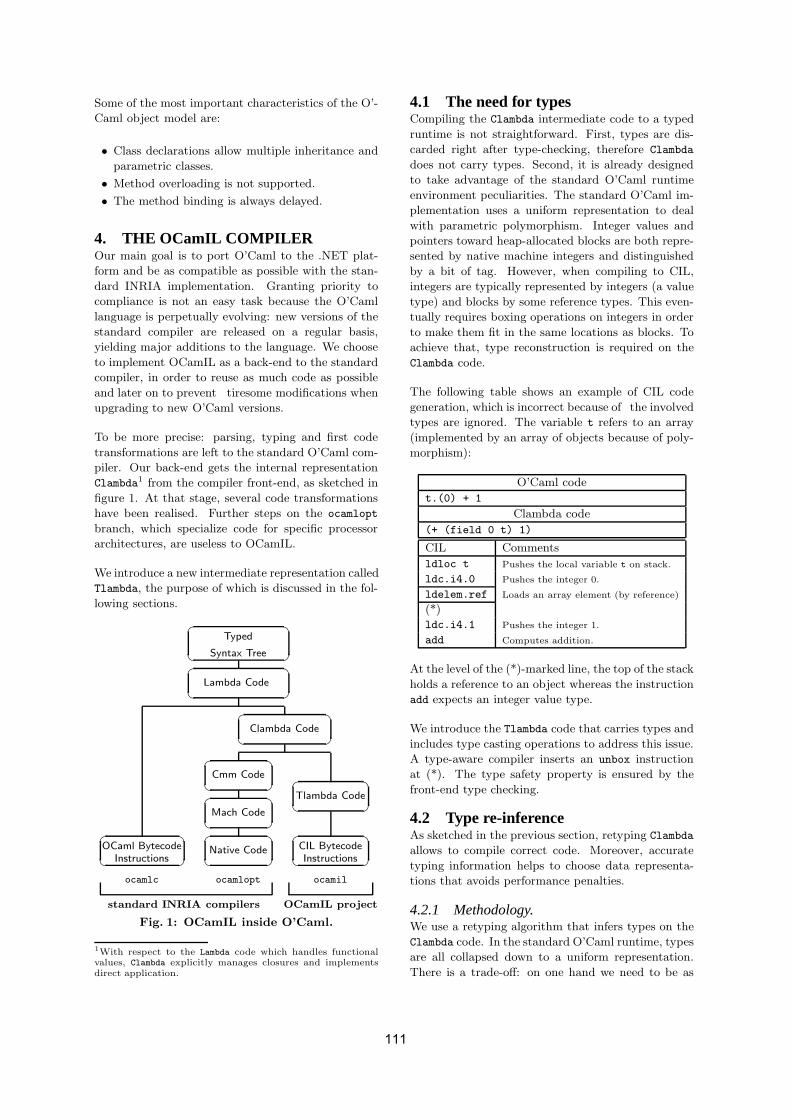
Some of the most important characteristics of the O’-
Caml object model are:
• Class declarations allow multiple inheritance and
parametric classes.
• Method overloading is not supported.
• The method binding is always delayed.
4. THE OCamIL COMPILEROur main goal is to port O’Caml to the .NET plat-
form and be as compatible as possible with the stan-
dard INRIA implementation. Granting priority to
compliance is not an easy task because the O’Caml
language is perpetually evolving: new versions of the
standard compiler are released on a regular basis,
yielding major additions to the language. We choose
to implement OCamIL as a back-end to the standard
compiler, in order to reuse as much code as possible
and later on to prevent tiresome modifications when
upgrading to new O’Caml versions.
To be more precise: parsing, typing and first code
transformations are left to the standard O’Caml com-
piler. Our back-end gets the internal representation
Clambda1 from the compiler front-end, as sketched in
figure 1. At that stage, several code transformations
have been realised. Further steps on the ocamlopt
branch, which specialize code for specific processor
architectures, are useless to OCamIL.
We introduce a new intermediate representation called
Tlambda, the purpose of which is discussed in the fol-
lowing sections.
CIL Bytecode
�
�
�
�
�
�
�
�
�
�
�
�
�
�
�
�
�
�
�
�
�
�
�
�
�
�
�
�
�
�
�
�
�
�
�
�
ocamilocamlc ocamlopt
standard INRIA compilers OCamIL project
OCaml BytecodeInstructions
Tlambda Code
Clambda Code
Cmm Code
Mach Code
Native Code
Syntax Tree
Lambda Code
Typed
Instructions
Fig. 1: OCamIL inside O’Caml.
1With respect to the Lambda code which handles functionalvalues, Clambda explicitly manages closures and implementsdirect application.
4.1 The need for typesCompiling the Clambda intermediate code to a typed
runtime is not straightforward. First, types are dis-
carded right after type-checking, therefore Clambda
does not carry types. Second, it is already designed
to take advantage of the standard O’Caml runtime
environment peculiarities. The standard O’Caml im-
plementation uses a uniform representation to deal
with parametric polymorphism. Integer values and
pointers toward heap-allocated blocks are both repre-
sented by native machine integers and distinguished
by a bit of tag. However, when compiling to CIL,
integers are typically represented by integers (a value
type) and blocks by some reference types. This even-
tually requires boxing operations on integers in order
to make them fit in the same locations as blocks. To
achieve that, type reconstruction is required on the
Clambda code.
The following table shows an example of CIL code
generation, which is incorrect because of the involved
types are ignored. The variable t refers to an array
(implemented by an array of objects because of poly-
morphism):
O’Caml code
t.(0) + 1
Clambda code
(+ (field 0 t) 1)
CIL Comments
ldloc t Pushes the local variable t on stack.
ldc.i4.0 Pushes the integer 0.
ldelem.ref Loads an array element (by reference)
(*)
ldc.i4.1 Pushes the integer 1.
add Computes addition.
At the level of the (*)-marked line, the top of the stack
holds a reference to an object whereas the instruction
add expects an integer value type.
We introduce the Tlambda code that carries types and
includes type casting operations to address this issue.
A type-aware compiler inserts an unbox instruction
at (*). The type safety property is ensured by the
front-end type checking.
4.2 Type re-inferenceAs sketched in the previous section, retyping Clambda
allows to compile correct code. Moreover, accurate
typing information helps to choose data representa-
tions that avoids performance penalties.
4.2.1 Methodology.We use a retyping algorithm that infers types on the
Clambda code. In the standard O’Caml runtime, types
are all collapsed down to a uniform representation.
There is a trade-off: on one hand we need to be as
111
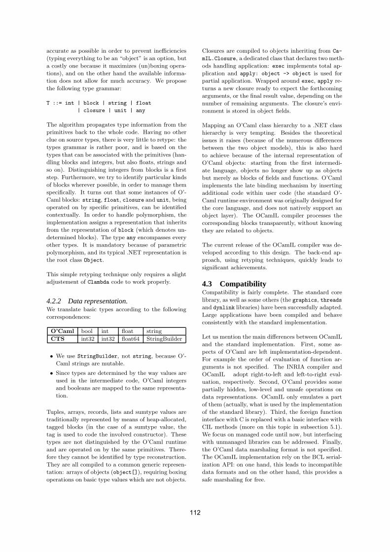
accurate as possible in order to prevent inefficiencies
(typing everything to be an “object” is an option, but
a costly one because it maximizes (un)boxing opera-
tions), and on the other hand the available informa-
tion does not allow for much accuracy. We propose
the following type grammar:
T ::= int | block | string | float
| closure | unit | any
The algorithm propagates type information from the
primitives back to the whole code. Having no other
clue on source types, there is very little to retype: the
types grammar is rather poor, and is based on the
types that can be associated with the primitives (han-
dling blocks and integers, but also floats, strings and
so on). Distinguishing integers from blocks is a first
step. Furthermore, we try to identify particular kinds
of blocks wherever possible, in order to manage them
specifically. It turns out that some instances of O’-
Caml blocks: string, float, closure and unit, being
operated on by specific primitives, can be identified
contextually. In order to handle polymorphism, the
implementation assigns a representation that inherits
from the representation of block (which denotes un-
determined blocks). The type any encompasses every
other types. It is mandatory because of parametric
polymorphism, and its typical .NET representation is
the root class Object.
This simple retyping technique only requires a slight
adjustement of Clambda code to work properly.
4.2.2 Data representation.We translate basic types according to the following
correspondences:
O’Caml bool int float string
CTS int32 int32 float64 StringBuilder
• We use StringBuilder, not string, because O’-
Caml strings are mutable.
• Since types are determined by the way values are
used in the intermediate code, O’Caml integers
and booleans are mapped to the same representa-
tion.
Tuples, arrays, records, lists and sumtype values are
traditionally represented by means of heap-allocated,
tagged blocks (in the case of a sumtype value, the
tag is used to code the involved constructor). These
types are not distinguished by the O’Caml runtime
and are operated on by the same primitives. There-
fore they cannot be identified by type reconstruction.
They are all compiled to a common generic represen-
tation: arrays of objects (object[]), requiring boxing
operations on basic type values which are not objects.
Closures are compiled to objects inheriting from Ca-
mIL.Closure, a dedicated class that declares two meth-
ods handling application: exec implements total ap-
plication and apply: object -> object is used for
partial application. Wrapped around exec, apply re-
turns a new closure ready to expect the forthcoming
arguments, or the final result value, depending on the
number of remaining arguments. The closure’s envi-
ronment is stored in object fields.
Mapping an O’Caml class hierarchy to a .NET class
hierarchy is very tempting. Besides the theoretical
issues it raises (because of the numerous differences
between the two object models), this is also hard
to achieve because of the internal representation of
O’Caml objects: starting from the first intermedi-
ate language, objects no longer show up as objects
but merely as blocks of fields and functions. O’Caml
implements the late binding mechanism by inserting
additional code within user code (the standard O’-
Caml runtime environment was originally designed for
the core language, and does not natively support an
object layer). The OCamIL compiler processes the
corresponding blocks transparently, without knowing
they are related to objects.
The current release of the OCamIL compiler was de-
veloped according to this design. The back-end ap-
proach, using retyping techniques, quickly leads to
significant achievements.
4.3 CompatibilityCompatibility is fairly complete. The standard core
library, as well as some others (the graphics, threads
and dynlink libraries) have been successfully adapted.
Large applications have been compiled and behave
consistently with the standard implementation.
Let us mention the main differences between OCamIL
and the standard implementation. First, some as-
pects of O’Caml are left implementation-dependent.
For example the order of evaluation of function ar-
guments is not specified. The INRIA compiler and
OCamIL adopt right-to-left and left-to-right eval-
uation, respectively. Second, O’Caml provides some
partially hidden, low-level and unsafe operations on
data representations. OCamIL only emulates a part
of them (actually, what is used by the implementation
of the standard library). Third, the foreign function
interface with C is replaced with a basic interface with
CIL methods (more on this topic in subsection 5.1).
We focus on managed code until now, but interfacing
with unmanaged libraries can be addressed. Finally,
the O’Caml data marshaling format is not specified.
The OCamIL implementation rely on the BCL serial-
ization API: on one hand, this leads to incompatible
data formats and on the other hand, this provides a
safe marshaling for free.
112

4.4 BootstrappingWe describe here the different steps that lead from
OCamIL sources to a bootstrapped compiler running
in the .NET framework. Like the O’Caml compiler
itself, OCamIL is written in the O’Caml language.
More than our personal preferences for O’Caml, it
is convenient to use the implementation language of
the standard INRIA compiler because we open a new
compilation branch on it.
The successive steps needed for building and boot-
strapping OCamIL are shown in figure 2. Compiling
OCamIL from sources requires the original O’Caml
bytecode compiler (ocamlc) and runtime (referred to
as µ). In the figure, mlB stands for the original O’-
Caml bytecode.
µ
ocamil
ocamilpre−
(src)ocamil
(src)ocamil ocamil
pre−
(src)ocamil
ML
mlB
ML ML
MLocamil
ML
ML ML
ML
MSIL
CLR
ocamil−2
ocamil−3
ML
mlB
ML ML mlB mlB
ML
ocamlc
mlB mlB
Building Steps
Bootstrapping Steps
CILCIL
ML
ML ML
MLocamil−2
ocamil
CLR
CIL
CIL
CILCIL
CIL
CIL CIL CIL
CILCIL
CIL
CILCIL CIL CIL
µ
(src)
Fig. 2: Building and bootstrapping steps
4.4.1 Building steps(following figure 2): the hybrid compiler pre-ocamil
is compiled first. It produces CIL executables and
shared libraries from O’Caml source files, but still
runs in the standard O’Caml environment. Then we
recompile OCamIL sources using the freshly compiled
compiler. This produces ocamil, which is itself a
.NET bytecode executable file. Once this is done, we
no longer need the O’Caml system nor the pre-ocamil
compiler 2.
4.4.2 Bootstrapping steps(following figure 2): we use the newly built compiler
to compile itself. We need two rounds to reach a fix-
point (ocamil-2 is identical to ocamil-3) because of
the slight difference of operational semantics exposed
in subsection 4.3 (regarding evaluation order). When
compiling OCamIL, it affects the ordering of code gen-
eration. For that matter, pre-ocamil and ocamil do2Later on, the pre-ocamil compiler should not be used, be-cause it runs in a different world than executables it produces.As explained in subsection 4.3, the O’Caml and OCamIL datamarshaling formats are not compatible. This implies thatdata marshaled by programs compiled by pre-ocamil cannotbe read back by pre-ocamil, a situation that typically hap-pens when compiling from a marshaled abstract syntax treeinstead of a source file (as preprocessors generate), or for dy-namic linking. This also means that libraries compiled bypre-ocamil cannot be used by ocamil: they need to be com-piled by ocamil itself.
not strictly behave the same, so ocamil and ocamil-2
are not strictly identical. In this case it does not af-
fect the semantics of the resulting programs but only
their code layout. The additional round fixes the mis-
match.
4.5 Toplevel BuildingThe OCamIL compiler and executables compiled by it
run in the CLR altogether. Using the .NET dynamic
code generation and execution features provided by
the reflection API helps building a toplevel utility
ocamiltop. A toplevel iteratively compiles O’Caml
declarations on the fly and executes them, while main-
taining a symbol table. Figure 3 displays the toplevel
components and shows the processing steps of an O’-
Caml expression.
5bocamil
phrase1
phrasenphrase1
ocamiltopApplication
Domain
phrasen-
� -
?
�-
6
6 66?6?
� z.......................................................................................................
:.....................
.........................................
.........................................
SymTableToplevelEngine
Toplevel
Output
1Input
2
Disk
2
34
4
...
BCLReflection
6
...
(5c)
5a
Engine
Fig. 3: The toplevel engine
1) The toplevel engine consumes an O’Caml expres-
sion phrasen.
2) It uses the ocamil compiler engine (together with
a Symbol Table resolving free variables) to compile
the expression to CIL code.
3) The CIL code is written as a shared library file on
the hard disk.
4) The toplevel engine calls the BCL System.Reflec-
tion.Assembly::LoadFrom method to dynamically
load back the emitted assembly to memory.
5a) Calls to the reflection API manage to run a public
method of the assembly which was emitted at stage
2. It is a startup method for the compiled expression.
5b) The startup method first registers the bindings
defined by phrasen by accessing directly the table of
symbols used by the toplevel. 5c) The startup method
then runs the inner code of phrasen (that may refer
to previous expressions using the associations main-
tained in the table of symbols).
6) The execution flow returns to the toplevel loop that
handles output (typically by displaying computed val-
ues).
113

The toplevel prototype writes compiled assemblies to
disk, then reloads them back to memory. We plan
to develop a new version that directly compiles code
to memory: this allows to produce a single assembly
that grows up during the toplevel session, from which
we expect increased performance.
The toplevel tool is very useful for application devel-
opment. It also has promising applications using its
embedding capabilities.
5. INTEROPERABILITYOCamIL interoperability capabilities are based on a
two-layered approach.
5.1 Basic Foreign Function InterfaceThe heart of OCamIL interoperability is a simple mech-
anism which allows to call CIL code from O’Caml
programs. It is a replacement of the original O’Caml
FFI for C code. OCamIL allows to call static methods
written in C# or in bytecode. This was widely used in
order to adapt the O’Caml standard library, replacing
the C code by calls to the .NET BCL. However, this
is limited and not type-safe: its main purpose is to
support safe, high-level communication.
5.2 O’JACARE.NETWe provide a high-level, safe interfacing of O’Caml
and C# through their object models, using an IDL
approach. We have developed a tool called O’Jaca-
re.net that compiles IDL files and generates all nec-
essary wrappers to mix components written in both
languages. Details can be found in [10].
5.2.1 Comparing object models.Type systems and object models can be interleaved
in many ways. There are important differences be-
tween the object models of O’Caml and C#. For in-
stance, class declarations allow multiple inheritance
and parametric classes in O’Caml but not in C#,
method overloading and class downcasting are only
supported in C# (but in O’Caml the type of self
can appear in the type of a method eventually overrid-
den in a subclass). The intersection of the two mod-
els corresponds to a simple class-based language, for
which inheritance and subtyping relations are equiva-
lent, overloading and binary methods are not allowed.
For the sake of simplicity, it does not offer multiple in-
heritance nor parametric classes. This model inspires
a basic IDL for interfacing C# and O’Caml classes.
5.2.2 Encapsulation.In contrast to direct external calls presented above,
using O’Jacare.net is safe and much more expres-
sive. O’Caml programs can allocate C# objects and
call instance methods. It is also possible to inherit
C# classes in O’Caml and redefine methods. Late-
binding is transparently performed between the two
languages. The other way around is also possible: li-
braries compiled by OCamIL can expose classes that
will be used in C# programs.
This requires a tricky implementation because O’-
Caml objects are no longer objects at run-time. The
mechanism that enables late-binding to run back and
forth between O’Caml and C# worlds is illustrated
in figure 4. In this example, a C# component defines
the well-known didactical classes Point and Colored-
Point that are exposed in an IDL file.
The compilation of this file generates the correspond-
ing O’Caml wrappers, allowing to allocate objects
and call methods upon the foreign C# classes as if
they were native. New O’Caml classes, such as colo-
red point ml in the figure, can inherit from them.
However, a complete and proper cross-language late-
binding mechanism cannot be implemented with such
a simple design. Let us assume that Point defines a
method toString, and that ColoredPoint both de-
fines a method getColor and overrides the definition
of toString by concatenating the results of a call
to the method getColor and a call to the method
toString of the superclass. If we redefine the getColor
method in O’Caml, and expect the toString method
to be specialized through late binding, we need to
produce an additional stub in each language: a call
to toString on colored point ml traces back to the
ColoredPoint class, which has no idea of the O’Caml
instance and thus of the redefinition of getColor.
The two stubs hold a reference to each other. The
C# stub, named ColoredPointStub, overrides each
method as a callback to the O’Caml stub callback co-
lored point and the latter defines each method as
a non-virtual call to ColoredPoint, the base-class of
the former. Following figure 4, the O’Caml class mi-
xed colored point inherits from the O’Caml stub class.
Thanks to the non-virtual call, a call to the toString
method traces back to the implementation of Colo-
redPoint Then the virtual call to getColor is late
bound to ColoredPointStub, which virtually calls the
O’Caml corresponding method on callback colored-
point, falling back on O’Caml late-binding mecha-
nism.
5.2.3 Blending two object models.O’Jacare.net allows to partially handle both object
models. [10] gives examples of C# objects downcast-
ing and multiple inheritance of C# classes in O’Caml.
We need the IDL glue to interoperate between O’-
Caml and C#: because of design and semantics dif-
ferences, encapsulation is needed in both ways. How-
ever, we benefit from sharing the same runtime envi-
114

� � � � � � � � � � � � � � � � � � �� � � � � � � � � � � � � � � � � � �� � � � � � � � � � � � � � � � � � �
� � � � �� � � � �� � � � �
� � � � � � � � � � � �
� � � � �
� � � � � � �
� � � � � � � � � � � � � � � �� � � � � � !
� � " � � # � � � � � � # � � � � �
$ % % & ' ( ) % * % ) % + , % - & . + / / /
0 � 1 � � �
2 ( + 3 4 5 ) 6 7 7 % + , . 3 %8 % + % ) ( 7 % 3 , . 3 % 9 ' 7 ( ) 7 6 + : * ) . ; 7 < % = > ? @
� � � � � � # � � � � � # � �
8 % + % ) ( 7 % 3 , . 3 % 5 6 7 < 7 < % , ( A A B ( , C ( 7 7 ) 6 B - 7 %
� � � � � � � � � � � # � � � � �
Fig. 4: Relationship between classes
ronment. The communication between components is
type safe and we take advantage of unified garbage
collection and thread management.
6. APPLICATIONSAdapting O’Caml to .NET is interesting for both com-
munities. We believe it can help make popular O’-
Caml applications, and that new possibilities are of-
fered by interoperability. Let us mention a few of
them.
O’Caml is given access to new libraries. O’-
Caml programs can use libraries ranging from graph-
ical toolkits to remoting facilities. They can be dis-
tributed as applets that run inside a browser’s win-
dows. See figure 5 for an example of O’Caml applet,
that runs a raytracer (the winning entry of the ICFP
2000 programming contest). Using O’Jacare.net,
the same O’Caml program can be given a graphical
user interface written in C#.
See also figure 6 for an O’Caml toplevel embedded in
a graphical interface written in C#.
O’Caml benefits from new tools. We can already
use .NET tools such as debuggers or profilers on OCa-
mIL programs. It is also possible to integrate the O’-
Caml language in IDE such as Visual Studio.NET.
.NET is enriched by O’Caml. It is important to
promote programming paradigms such as functional
programming. Moreover, the O’Caml object layer
can interest OO programmers and encourage them
to give O’Caml a try. O’Caml is particularly good at
tree manipulations or symbolic computations, some of
the fields where languages such as C# cannot stand
the comparison. Syntactical tools such as Camlp4
[11], which was successfully compiled by OCamIL, can
open new tracks for writing compilers, using O’Caml
as a target language. The possibility to embed an
O’Caml toplevel component in C# applications also
offers interesting perspectives.
7. RELATED WORKThe approach described for O’Jacare.net (two run-
time environments running side by side) has also been
used in other projects.
The Haskell interpreter, Hugs98 for .NET [12], allows
.NET classes. Its implementation is based on a mech-
anism similar to O’Caml / O’Jacare.net. At the
level of source language, it allows a basic communica-
tion with the .NET platform which allows thorough
communication to be built upon and used through
a high level language construction. Automatic code
generation with a dedicated tool is needed to achieve
it. As for execution, it provides two virtual machines
(interpreter and CLR) running simultaneously. The
Dot-Scheme [13] project implements a FFI (Foreign
Function Interface) to the .NET platform from PLT
Scheme. Here again, execution is performed by two
virtual machines. At the language level, the imple-
mentation (based on CLR introspection capabilities)
allows an easy and direct .NET classes manipulation.
The current trend is to directly produce bytecode for
either Java (cf MLj [14]), or .NET. For .NET, a lot
of works have been done :
• for SML: SML.NET [15] and MoscowML
for .NET [16];
• for O’Caml: F# [17] and OCamIL.
115

Fig. 5: An applet running a raytracer written in O’Caml.
The main interest to use the same runtime is to facili-
tate memory management (GC) and multi-threading.
F# and OCamIL illustrate two different views of in-
teroperability. F# conception is focused on inter-
operability. Its purpose is to manipulate the .NET
proposed object model in a functional / imperative
language similar to CamlLight. The outcome is a
new Caml dialect using .NET object model. But the
.NET object model is really far from the O’Caml ob-
ject model. The advantage is to directly manipulate
CTS types, with no additional tool and in a natural
way. It provides a comfortable programming and al-
lows an implementation as direct as possible (which
guaranties better performance).
On the other hand, the used object model is not in-
tegrated as well in the functional paradigm as the
O’Caml model. In many cases, it is mandatory to
help the type inference by giving types annotations
for CTS. Then, parametric polymorphism and row
polymorphism become a kind of interfaces polymor-
phism when .NET methods are called.
On the contrary, OCamIL does not modify the orig-
inal language. There are no new constructs coming
from the target architecture and the interoperability
is managed accross the O’Caml object model.
There are two main consequences :
• the difference between the two object models for-
bids a direct compilation from O’Caml objects to
the CTS;• this inadequacy makes it necessary to generate
stub classes (we compile IDL files with our tool
O’Jacare.net).
To put it shortly, F# is for the C# programmer who
wants to use functional programming, and OCamIL
is for the O’Caml programmer, who wants to take
advantage of the .NET environment without changing
his favorite language.
MLj and SML.NET join together the two approaches
by proposing the essence of SML on the Java and
.NET platforms, and integrating the C# object model
(but it is true that without object features in the orig-
inal languages there is no decision to select an ob-
ject model). MoscowML for .NET only allows static
method calls.
From the Scheme side, the Bigloo compiler allows to
compile to the JVM or the CLR runtimes. As for Dot-
Scheme, the .NET features are nicely incorporated in
the Scheme language by using special functions and
macros. The Scheme language fits well in an inter-
operability setting: its syntax is easily extensible and
its dynamic typing facilitates the integration of new
features. Dynamic typing is more in the spirit of the
Java and .NET platforms that propose many services
of instrospection.
Although Eiffel is not a functional language, its .NET
version [18] encounters similar difficulties than OCa-
mIL. The two object models have a multiple inheri-
116

Fig. 6: A toplevel session in a C# window, demonstrating culture-specific ordering.
tance, parametric classes and no overloading. How-
ever their techniques of compilation strongly differ.
Eiffel relies on CTS interfaces to emulate multiple in-
heritance.
8. RETYPING TECHNIQUES AND FU-TURE WORK
For the sake of compatibility and front-end indepen-
dence, OCamIL currently adopts a back-end approach
that leads to retype an intermediate language from
scratch. We are currently developing an alternative
implementation which retrieves source types from the
O’Caml type-checking step. Let us compare the pros
and cons of each technique.
8.1 What hinders the strict back-end ap-proach
As mentioned in subsection 4.2, the retyping tech-
nique requires the front-end to be slightly modified.
The heart of the problem are data types with non-
uniform representations such as sumtypes. Here is a
sample sumtype definition:
type t = Zero | One | Node of t
The sumtype t declares two constant constructors and
a non-constant constructor. As for the O’Caml run-
time, these are respectively represented by integers 0,
1 and a pointer to a block containing another value
of type t. This is homogeneous in the O’Caml run-
time but the retyping algorithm eventually infers two
different types, int and block, for values of type t.
Consider the following function and its compiled rep-
resentation in Clambda code:
O’Caml code Clambda code
let cut x = let cut = closure(cut):
match x with x ->
| Node n -> n if (isint x) then x
| x -> x else (field 0 x)
Type Inferred type
t -> t Sumtype -> Sumtype
The isint primitive tests the bit of tag that dis-
tinguishes integers from pointers on blocks. In or-
der to take the duplicity of the parameter x into ac-
count, the grammar of reconstructed types needs a
new item Sumtype, that represents the union of int
and block. The function cut above receives the type
Sumtype -> Sumtype. We do not want to use the
general-purpose type any here to give a chance to
Sumtype values to be mapped to a more precise and
adequate type than Object. Of course, applying cut
to constants requires boxing operations. There is
something wrong though, as the following example
reveals:
O’Caml code Clambda code
let hell a b = let hell = closure(hell):
match a with a -> b ->
| Zero if (isint a) then
(if (a != 0) then b
-> One else 1)
| _ -> b else b
Type Inferred type
t -> t -> t Sumtype -> int -> int
The type of the parameter b is problematic. Looking
at the O’Caml source code we know that a and b are
both of type t. But looking at the Clambda code, one
is tempted to claim that b is an integer! The only in-
117
formation that the re-typing algorithm has about b is
that its type is unifiable with int (because of the sub-
expression: if (a != 0) then b else 1). Following
the policy of being as accurate as possible, b is typed
to be an integer, and the function hell receives the
type Sumtype -> int -> int. Later on, when com-
piling an application such as hell One (Node Zero),
the retyping algorithm detects inconsistency and aborts.
In general, the algorithm cannot backtrack and give
b a correct type: the definition of hell and its appli-
cations can reside in separately compiled modules.
Fortunately, there is a simple workaround. Changing
the representation of sumtypes a little bit is a quick
modification of the compiler. Because constant con-
structors can be encoded as empty blocks (the tag of
the block coding the constructor), we uniformly repre-
sent sumtypes by blocks 3. This avoids the multiplic-
ity of representations for the same type that caused
types reconstruction errors. Although this is achieved
by a slight modification of the compiler, this somehow
betrays the spirit of the back-end approach.
8.2 Types propagationThe retyping of the Clambda intermediate language is
not accurate enough, entailing costly data structure
allocation (object arrays). Data access is slowed down
by dynamic typechecking and boxing operations. Re-
trieving exact types allows to compile data to ade-
quate representations: for instance each constructor
of a given sumtype can be implemented as an ob-
ject with fields holding the parameters of construc-
tor, with their exact types. We propose to modify
the implementation of O’Caml in order to propagate
typing information along intermediate languages from
the type-checking step until the Clambda code. Main-
taining OCamIL up to date with the latest O’Caml re-
lease will be harder because types are likely to evolve
along with O’Caml development, but as explained in
the previous subsection a strict back-end implemen-
tation quickly reaches its limits anyway. Future work
will focus on implementing and exploiting type prop-
agation, and we expect important performance im-
provements. Type propagation also has applications
in debugging O’Caml programs, because the gener-
ated CIL will have more adequate types with respect
to the O’Caml source program.
9. CONCLUSIONJava’s success has popularized bytecode-based run-
timesthat offer modern techniques to improve safety,
such as typed bytecode, garbage collection and built-
in security policies. The .NET CLR is based on a
3A more complex policy can be imagined for sumtypes: rep-resented by integers if made of constant constructors only,and represented by blocks otherwise. However this is not ap-propriate for O’Caml polymorphic variants which can be in-crementally extended, for example by adding a non constantconstructor to a set of constant constructors.
similar design, and tries to improve security. These
two platforms help portability, interoperability and
offer a convenient target for compiler implementors.
The OCamIL project helps to evaluate the .NET plat-
form and the O’Caml implementation with respect to
each other. The .NET CLR is presented as a runtime
of choice to run multi-languages applications, which
implies a stricter control over pieces of code and the
addition of new features to the execution platform, in
order to support more programming features. How-
ever, these efforts have been mainly object-oriented:
originally for C#, Visual Basic and C++. Logical
and functional paradigms are not natively supported.
Closures and advanced flow-control (even exceptions)
implementation is too costly. Likewise, parametric
polymorphism does not fit well in the object models
of today’s runtimes. Fortunately, there are promising
developments towards these directions (such as ILX
and generics).
Symmetrically, language implementations need to ad-
apt to new runtimes. Compiling to a typed virtual
machine raises new issues that were not relevant in
dedicated functional virtual machines [19]: now type
information is needed down to bytecode generation.
To address efficiency issues, types have to be as ac-
curate as possible, ideally by propagating the static
type-checking step information. Appel’s slogan “Run-
time Tags Aren’t Necessary” [20] does not hold any-
more.
For the sake of compatibility and front-end indepen-
dence, OCamIL has adopted a back-end approach
that leads to retyping an intermediate language from
scratch. We are currently developing an alternative
implementation which retrieves source types from the
O’Caml type-checking step. The solution needs to
modify the implementation of O’Caml in order to
propagate typing information along intermediate lan-
guages from the type-checking step until the Clambda
code, which is successfully experimented with the de-
velopment version of OCamIL.
Despite these inadequacies, the .NET platform has
proven to be an interesting framework to develop a
compiler for. The OCamIL compiler and toplevel al-
low the development of O’Caml applications for the
.NET platform, with the guarantee of compatibility
with O’Caml (including advanced programming fea-
tures) and managed CIL code production. Other .NET
languages can consume O’Caml components, for in-
stance the OCamIL toplevel can be embedded inside
a C# application, to produce dynamically compiled
O’Caml code.
118

10. REFERENCES[1] Thai, T.L., Lam, H.: .NET Framework
Essentials. 3rd edn. O’Reilly Edt (2003)
[2] Stutz, D., Neward, T., Shilling, G.: Shared
Source CLI. O’Reilly Edt (2003)
[3] Dumbill, E., Bornstein, N.: Mono: A
Developer’s Notebook. Developers’ Notebooks.
O’Reilly Edt (2004)
[4] Leroy, X.: The Objective Caml system release
3.06 : Documentation and user’s manual.
Technical report, Inria (2002)
http://caml.inria.fr.
[5] Montelatici, R., Chailloux, E., Pagano, B.:
OCamIL homepage (2004) http:
//www.pps.jussieu.fr/~montela/ocamil.
[6] Syme, D.: ILX: Extending the .NET common
IL for functional language interoperability.
Electronic Notes in Theoretical Computer
Science 59 (2001)
[7] Kennedy, A., Syme, D.: Design and
Implementation of Generics for the .NET
Common Language Runtime. In: Proceedings of
the Conference on Programming Language
Design and Implementation (PLDI), ACM
SIGPLAN (2001)
[8] Yu, D., Kennedy, A., Syme, D.: Formalization
of Generics for the .NET Common Language
Runtime. In: Proceedings of the 31st
Symposium on Principles of Programming
Languages (POPL), ACM SIGPLAN (2004)
[9] Remy, D., Vouillon, J.: Objective ML: An
effective object-oriented extension to ML.
Theory and Practice of Object Systems 4
(1998) 27–50
[10] Chailloux, E., Henry, G., Montelatici, R.:
Mixing the Objective Caml and C#
programming models in the .NET framework.
In: Proceedings of Int. Worshop on
Multiparadigm Programming with OO
languages (MPOOL’04). (2004)
[11] de Rauglaudre, D.: camlp4 : Reference manual.
Technical report, Inria (2002)
http://caml.inria.fr.
[12] Finne, S.: Hugs98 for .NET homepage (2003)
galois.com/~sof/hugs98.net.
[13] Pinto, P.: Dot-Scheme: A PLT Scheme FFI for
the .NET framework. In Flatt, M., ed.: Scheme
Workshop. (2003) 16–23
[14] Benton, N., Kennedy, A.: Interlanguage
Working Without Tears: Blending SML with
Java. In: International Conference on
Functional Programming. (1999)
[15] Benton, N., Kennedy, A., Russo, C., Russell,
G.: sml.net homepage (2005)
www.cl.cam.ac.uk/Research/TSG/SMLNET/.
[16] Kokholm, N., Sestoft, P.: Moscow ML .Net
Internals. (2003) http://www.dina.dk/
~sestoft/mosml.html#mosmlnet.
[17] Syme, D.: F# homepage (2005)
http://research.microsoft.com/projects/
ilx/fsharp.aspx.
[18] Simon, R., Stapf, E., Meyer, B.: Full eiffel on
the .net framework. MSDN Library, http:
//msdn.microsoft.com/library/default.asp?
url=/library/en-uspdc_eiffel.asp (2002)
[19] Leroy, X.: The effectiveness of type-based
unboxing. In: Workshop on Types in
Compilation. (1997)
[20] Appel, A.: Runtime tags aren’t necessary. Lisp
and Symbolic Computation (1989)
119

120

Implementing an OCL Compiler for .NET
László Lengyel Budapest University of
Technology and Economics Goldmann György tér 3. Hungary 1111, Budapest
Tihamér Levendovszky Budapest University of
Technology and Economics Goldmann György tér 3. Hungary 1111, Budapest
Hassan Charaf Budapest University of
Technology and Economics Goldmann György tér 3. Hungary 1111, Budapest
ABSTRACT
Model-Driven Architecture standardized by OMG facilitates separating the platform-independent part (PIM) and
the platform-specific part (PSM) of a system model. The platform-independent artifacts are mainly UML models
created with CASE tools. Due to this separation, PIM specified by the developers can be reused across several
implementation platforms of the software. PSM is ideally generated automatically from PIM via model
transformation steps performed by model compilers. Beyond the topology of the visual models additional
constraints must be specified, which ensure the correctness of the attributes among others. Dealing with OCL
constraints provides a solution for the unsolved issues, because topological and attribute transformation methods
cannot perform and express the problems that can be addressed by constraint validation. This paper discusses the
need for combining UML and OCL, it introduces the compilers in general, it shows the architecture of our OCL
Compiler for .NET, and it presents the lexical and syntactic analysis as well as the semantic analysis and code
generation techniques in detail. The OCL Compiler has been implemented as a module of our n-layer
multipurpose modeling and metamodel-based transformation system called Visual Modeling and Transformation
System (VMTS). The OCL Compiler module facilitates validating (i) constraints contained by the metamodels at
the time of the model instantiation process, and (ii) constraints contained by the transformation steps during the
metamodel-based graph transformation. An illustrative case study is also provided, which introduces how VMTS
generates source code from a statechart diagram, and how it validates specific properties using the OCL
Compiler.
Keywords OCL Compiler, .NET, Constraints, Constraint Validation, UML, Metamodeling, VMTS
1. INTRODUCTION Model transformation is a possible solution for
realizing model compiler. Its methods are vital in
several applications, for instance the Object
Management Group’s (OMG) Model-Driven
Architecture (MDA) standard [OMG03a] strongly
builds on model compilers, which automatically
create a platform-specific model from the platform-
independent models specified by the modelers.
Software model transformation provides a basis for
model compilers, which plays a central role in the
MDA architecture.
There are many CASE tools that support drawing
UML diagrams and other features like code
generation and reverse engineering. However,
support for OCL attached to model transformation
and mappings between models are rarely found in
these tools. There are several tasks that a CASE tool
should offer in order to provide support for OCL. For
example, syntax analysis of OCL expressions and a
precise mechanism for reporting syntactic errors help
in writing syntactically correct OCL statements. An
important feature is the semantic analyzer, which
reports as many errors as possible in order to help the
user develop solid OCL code.
Often we need to specify a model more precisely than
a topology-oriented visual modeling language
facilitates it. It is a prevalent case that we want to
define expressions and constraints on our model. The
Permission to make digital or hard copies of all or part of
this work for personal or classroom use is granted without
fee provided that copies are not made or distributed for
profit or commercial advantage and that copies bear this
notice and the full citation on the first page. To copy
otherwise, or republish, to post on servers or to redistribute
to lists, requires prior specific permission and/or a fee.
.NET Technologies’2005 conference proceedings,
ISBN 80-86943-01-1
Copyright UNION Agency – Science Press, Plzen, Czech Republic
121

Object Constraint Language (OCL) [OCL03a] is a
formal language for analysis and design of software
systems. It is a subset of the industry-standard
Unified Modeling Language [UML03a] that allows
software developers to write constraints and queries
over object models. A constraint is a restriction on
one or more values of an object-oriented model or
system. There are four types of constraints. (i) An
invariant is a constraint that states a condition that
must always be met by all instances of the class, type,
or interface. (ii) A precondition to an operation is a
restriction that must be true at the moment before the
operation is executed. Obligations are specified by
postconditions. (iii) A postcondition to an operation
is a restriction that must be true at the moment that
the operation has just ended its execution. (iv) A
guard is a constraint that must be true before a state
transition fires. Besides these, OCL can be used as a
navigation language as well.
Our n-layer metamodel-based model storage and
transformation software package is called Visual
Modeling and Transformation System [Lev04a]
[Vis03a]. VMTS is implemented using Microsoft
.NET Framework [Mic03a] and illustrates an
approach, where model storage and model
transformation can be treated uniformly, and what
links them together is the notion of the metamodel.
Modeling environments built on metamodeling are
highly configurable (visual) modeling tools allowing
constraints to be specified in advance. VMTS uses
graph rewriting for model transformation as a
powerful tool with strong mathematical background
[Lev04a]. The atoms of graph transformation are
rewriting rules, where each rewriting rule consists of
a left hand side graph (LHS) and a right hand side
graph (RHS). Applying a graph rewriting rule means
finding an isomorphic occurrence (match) of LHS in
the graph to which the rule is being applied (host
graph), and replacing this subgraph with RHS.
Replacing means removing elements which are in
LHS but not in RHS, and gluing elements which are
in RHS but not in LHS. The graph transformation is
defined as an ordered sequence of rewriting rules, in
other words, we control the transformation process by
sequencing the rewriting rules. Previous work
[Lev04a] has introduced an approach, where LHS
and RHS of the rules are built from metamodel
elements. It means that an instantiation of LHS must
be found in the host graph instead of the isomorphic
subgraph of LHS. Hence LHS and RHS graphs are
the metamodels of the graphs which we find and
replace in the host graph.
Often it is not enough to match graphs using the
topological information only. There are cases in
which we want to restrict the desired match by other
properties, e.g. we want to match a subgraph with a
node which has a special property, or which has a
unique relation between the properties of the matched
nodes. The metamodel-based definition of the
rewriting rules facilitates assigning OCL constraints
to the pattern rule nodes contained by the
transformation steps, and with OCL these conditions
can be expressed easily. A precondition
(postcondition) assigned to a rewriting rule is a
Boolean expression that must be true at the moment
when the rewriting rule is fired (after the completion
of a rewriting rule). If a precondition of a rewriting
rule is not true then the rewriting rule fails without
being fired. If a postcondition of a rewriting rule is
not true after the execution of the rewriting rule, then
the rewriting rule fails. A direct corollary of this is
that an OCL expression in LHS is a precondition to
the rewriting rule, and an OCL expression in RHS is
a postcondition to the rewriting rule. A rewriting rule
can be fired if and only if all conditions enlisted in
LHS are true. Also, if a rewriting rule finished
successfully, then all the conditions enlisted in RHS
must be true.
Constraints (pre- and postconditions) facilitate
specifying precisely the execution of the steps
contained by the transformation. Using constraints for
each step, we can define the cases in detail, in which
the step can be fired, and, of course, in which not.
OCL Compiler
Metamodel
OCL constraints
in rewriting rule
Models
Instantiation
Validation
Code / binary
Matches
Matching
Checking
Rewriting
results
Firing the
rewriting rule
Use meta
elements Instantiation
Figure 1. Block diagram for checking constraints
during the rewriting process
Fig. 1 presents a block diagram to illustrate the
method how VMTS checks the rewriting rule
constraints during the rewriting process. It is possible
in VMTS that LHS and RHS use different
metamodels, but for the sake of simplicity in the
block diagram they have a common metamodel. The
rewriting rule contains OCL constraints. VMTS does
not interpret the constraints during the rewriting, but
an assembly is used that is generated by the OCL
Compiler. The rewriting process uses the matches
found by the matching process and the compiled
assembly to validate the constraints on the matched
parts of the host graph. The rewriting process
generates the rewriting result if and only if a match
satisfies the constraints (preconditions), and the step
is successful if and only if the rewriting result
122

satisfies the postconditions. In Fig. 1 the rewriting
result is also an instance model of the metamodel,
because LHS and RHS use the same metamodel.
One of the most important parts of the constraint
validation method is that our constraint checking
approach does not interpret the constraints; OCL
Compiler generates C# code and compiles it to an
assembly, which validates the metamodel and the
rewriting rule constraints. This method facilitates
determining the complexity of the constraint
validation method.
This paper introduces the steps necessary for the
implementation of the OCL Compiler for .NET,
which is capable of compiling OCL constraints into
source code and a binary file that checks the OCL
constraints on the rewriting rules of a transformation
that realizes an MDA model compiler. Our example
is a UML statechart model.
The rest of this paper is organized as follows: Section
2 introduces the concept of a compiler in general, it
presents the architecture of our OCL Compiler and it
discusses the lexical and syntactic analysis as well as
semantic analysis along with the code generation in
detail. In Section 3 we illustrate a case study how to
design a C# form behavior using Visual Studio.NET
Form editor, and how VMTS generates the user
interface handler code based on the statechart model.
In this way the programmer needs to write the
application-specific parts of the code only. Finally,
conclusions and future work are delineated in Section
4.
2. CONTRIBUTION This section presents the general considerations
related to compilers and their modules shortly and
examines the VMTS OCL Compiler in detail.
PreprocessingLexical
Analysis
Syntactic
Analysis
Semantic
Analysis
Platform
Independent
Optimization
Code
Generation
Platform
Dependent
Optimization
Inner Representation
Analysis
Synthesis
Figure 2. The steps of the compilation
Implementing a compiler is a complex task consisting
of several well-defined subparts. The input of a
compiler is a textual file written in the source
language, and the output is a textual file or a binary in
the target language. The source language and the
target language can be the same or different. The two
main parts of the compilation are: (i) the analysis of
the source language input, and (ii) the generation
(synthesis) of the target language output based on the
retrieved semantic information. Fig. 2 introduces the
steps of the compilation process.
Compiler Architecture The OCL Compiler is a part of VMTS, therefore the
generated code and the compiled assembly have to fit
in this environment. The block diagram of VMTS
and the place of the OCL Compiler in a metamodel-
based model transformation system are depicted in
Fig. 3. The user interfaces (Adaptive Modeler, Rule
Editor) are functionally separated from the model
storage unit (AGSI Core - Attributed Graph
Architecture Supporting Inheritance), which uses an
RDBMS (Microsoft SQL Server 2000) to store the
model information. Besides this the AGSI Core
exposes its interface to any other applications which
may use other technique to process AGSI data.
Figure 3. Block structure of VMTS
The OCL Interface provides a unified interface for
the user interface modules to access constraint
validation. If it is required, it uses the OCL Compiler
and loads the compiled binary (Compiled
Constraints). AGSI Core stores and handles the
models as labeled graphs: it simply uses nodes and
edges. In OCL constraints these nodes and edges
appear with their names as types, instances and
associations. The main purpose of the AGSI Interface
is to provide a linkage between the OCL expressions
and the model over which the expression should be
evaluated. AGSI provides type information from the
AGSI Core objects. During the compilation and the
constraint validation process we run only select
commands on the AGSI Core data, therefore AGSI
Interface does not support operations modifying the
model.
Lexical and Syntactic Analysis Lexical and syntactic analyses are realized by code in
the ANSI C language, it is generated by the tools Flex
[Fle99a] and Bison [Bis98a]. We chose these tools
because (i) the compiler is implemented using
Microsoft Visual Studio and it was easy to integrate
123
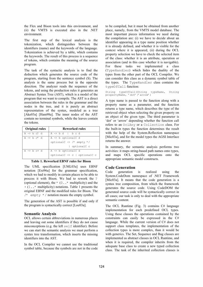
the Flex and Bison tools into this environment, and
(ii) the VMTS is executed also in the .NET
environment.
The first step of the lexical analysis is the
tokenization, which distinguishes between the
identifiers (name) and the keywords of the language.
Tokenization is achieved by a table, which contains
the keywords. The result of this process is a sequence
of tokens, which contains the meaning of the source
program.
The task of the syntactic analysis is to find the
deduction which generates the source code of the
program, starting from the sentence symbol (S). The
analysis is the same process but in the opposite
direction. The analyzer reads the sequence of the
tokens, and using the production rules it generates an
Abstract Syntax Tree (AST), which is a model of the
program that we want to compile. The AST is a direct
association between the rules in the grammar and the
nodes in the tree, and it is purely an abstract
representation of the syntax, modeled as a tree
[Ake03a] [Ham98a]. The inner nodes of the AST
contain no terminal symbols, while the leaves contain
the tokens.
Original rules Reworked rules
A -> b c? d A -> b d | b c d
A -> b c* d A -> b optionalC d
optionalC -> /* empty */
| optionalC c
A -> b c+ d A -> b optionalC d
optionalC -> c | optionalC c
Table 1. Reworked EBNF rules for Bison
The UML specification [UML03a] uses EBNF
notation [Ext96a] for the grammar specification,
which we had to modify in certain places to be able to
process it with Bison. We had to rework the ?
(optional element), the * (0..* multiplicity) and the
+ (1..* multiplicity) notations. Table 1 presents the
original EBNF and the modified rules for Bison. The
/* empty */ notation means the empty symbol.
The generation of the AST is possible if and only if
the program is syntactically correct [Loe03a].
Semantic Analysis OCL allows certain abbreviations in numerous places
and leaving out some identifiers if they do not cause
misconceptions (e.g. the left self identifier). Before
we can start the semantic analysis we must perform a
syntax tree transformation, which inserts the missing
identifiers into the AST.
In the OCL Compiler we cannot use the traditional
symbol table, because the symbols are not in the code
to be compiled, but it must be obtained from another
place, namely, from the VMTS model database. The
most important pieces information we need during
the compilation are: (i) we have to decide about an
identifier appearing in a type name position whether
it is already defined, and whether it is visible for the
context where it is appeared, (ii) during the OCL
property selection we have to check the selected item
of the class: whether it is an attribute, operation or
association (and in this case whether it is navigable).
For these tasks we implemented a class
(TypeHandler) which hides the duality of the
types from the other part of the OCL Compiler. We
can consider this class as a dynamic symbol table of
the types. The TypeHandler class contains the
typeOfCall function:
String typeOfCall(String typeName, String propertyName, ’dot’|’arrow’)
A type name is passed to the function along with a
property name as a parameter, and the function
returns a type name, which describes the type of the
retrieved object when selecting the given property on
an object of the given type. The third parameter is
‘dot’ or ‘arrow’ depending whether the function call
refers to an OclAny or a Collection class. For
the built-in types the function determines the result
with the help of the System.Reflection namespace
[Mic03a], and for the model types the AGSI Interface
returns the answer.
In summary, the semantic analysis performs two
activities: it maps string-based path names onto types,
and maps OCL specific operations onto the
appropriate semantic model constructs.
Code Generation Code generation is realized using the
System.CodeDom namespace of .NET Framework
[Mic03a]. It means that the code generation is a
syntax tree composition, from which the framework
generates the source code. Using CodeDOM the
generated source code will be syntactically correct in
all cases; our task is only to deal with the appropriate
semantic content.
The OCL Runtime (Fig. 3) contains C# language
implementation for each predefined OCL types.
Using these classes the operations contained by the
constraints can easily be expressed in the C#
language. While the current version of C# does not
support class templates, the implementation of the
collection types is more complex, than it would be
with generics. The Set, Sequence and Bag classes are
implemented as abstract classes in OCL Runtime, and
when it is required, the compiler inherits from the
adequate base class to create a new typed collection
class. The task of the inherited collection classes is
124
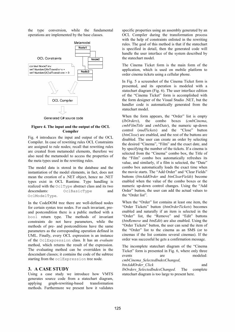
the type conversion, while the fundamental
operations are implemented by the base classes.
Figure 4. The input and the output of the OCL
Compiler
Fig. 4 introduces the input and output of the OCL
Compiler. In case of rewriting rules OCL Constraints
are assigned to rule nodes; recall that rewriting rules
are created from metamodel elements, therefore we
also need the metamodel to access the properties of
the meta types used in the rewriting rules.
The model data is stored in the database and the
instantiation of the model elements, in fact, does not
mean the creation of a .NET object, hence no .NET
types exist in OCL Runtime. Type handling is
realized with the OclType abstract class and its two
descendants: OclBasicType and
OclModelType.
In the CodeDOM tree there are well-defined nodes
for certain syntax tree nodes. For each invariant, pre-
and postcondition there is a public method with a
bool return type. The methods of invariant
constraints do not have parameters, while the
methods of pre- and postconditions have the same
parameters as the corresponding operation defined in
UML. Finally, every OCL expression is an instance
of the OclExpression class. It has an evaluate
method, which returns the result of the expression.
The evaluating method can be overridden in the
descendant classes; it contains the code of the subtree
starting from the oclExpression tree node.
3. A CASE STUDY Using a case study we introduce how VMTS
generates source code from a statechart diagram,
applying graph-rewriting-based transformation
methods. Furthermore we present how it validates
specific properties using an assembly generated by an
OCL Compiler during the transformation process
with the help of constraints enlisted in the rewriting
rules. The goal of this method is that if the statechart
is specified in detail, then the generated code will
handle the user interface of the system described by
the statechart model.
The Cinema Ticket form is the main form of the
application, which is used on mobile platform to
order cinema tickets using a cellular phone.
In Fig. 5 a screenshot of the Cinema Ticket form is
presented, and its operation is modeled with a
statechart diagram (Fig. 6). The user interface edition
of the “Cinema Ticket” form is accomplished with
the form designer of the Visual Studio .NET, but the
handler code is automatically generated from the
statechart model.
When the form appears, the “Order” list is empty
(lbOrders), the combo boxes (cmbCinema,
cmbFilmTitle and cmbDate), the numeric up-down
control (nudTickets) and the “Close” button
(btnClose) are enabled, and the rest of the buttons are
disabled. The user can create an order by selecting
the desired “Cinema”, “Film” and the exact date, and
by specifying the number of the tickets. If a cinema is
selected from the “Cinema” combo box, the Title of
the “Film” combo box automatically refreshes its
value, and similarly, if a film is selected, the “Date”
combo box automatically loads the exact time when
the movie starts. The “Add Order” and “Clear Fields”
buttons (btnAddOrder and btnClearFields) become
enabled when the value of the combo boxes or the
numeric up-down control changes. Using the “Add
Order” button, the user can add the actual values to
the “Order list”.
When the “Order” list contains at least one item, the
“Order Tickets” button (btnOrderTickets) becomes
enabled and naturally if an item is selected in the
“Order” list, the “Remove” and “Edit” buttons
(btnRemove and btnEdit) are also enabled. Using the
“Order Tickets” button, the user can send the item of
the “Order” list to the cinema as an SMS (or to
cinemas if the list contains several cinemas). If the
order was successful he gets a confirmation message.
The incomplete statechart diagram of the “Cinema
Ticket” form is presented in Fig. 6, where only three
events are modeled:
cmbCinema_SelectedIndexChanged,
btnAddOrder_Click and
lbOrders_SelectedIndexChanged. The complete
statechart diagram is too large to present here.
125

Figure 5. Cinema Ticket form for mobile platform
Figure 6. Statechart model of the Cinema Ticket
form
In Fig. 6 one can see that each event has at least one
handler state. E.g. if the On_btnAddOrder_Click
event is fired, then the btnAddOrder_Click state
handles it. The On_lbOrders_SelectedIndexChanged
event is managed by four states:
lbOrders_SelectedIndexChanged, lbOrdersCount1,
lbOrdersCount2, and After_lbOrdersCount. This
event handler is decomposed into sub-states, because
the handling code depends on the value of the
lbOrders.SelectedItem property.
The case study uses the statechart model (Fig. 6) as
an input model and applies a rewriting rule (Fig. 7) to
it. In the rewriting rule the LHS graph uses the meta-
elements of the Statechart metamodel [UML03a]
[Vis03a] and the RHS graph uses the meta-elements
of the CodeDOM metamodel [Mic03a] [Vis03a]. On
the left hand side of the rewriting rule there are two
states which correspond to the statechart state, and
there is a transition between them with a 0..*
multiplicity on the side of the target state. It means
that applying this rewriting rule exhaustively to a
statechart model, it matches all the states with their
target adjacent states. The rule has to match the
accessible adjacent states, because we need them to
generate the state-transitions into the source code. Of
course, it is possible that a state has no outgoing
transitions, and the reason why we enable the 0 in the
multiplicity is that we want to match states having
only incoming transitions in order to generate
CodeDOM tree for them as well. On the right hand
side of the rewriting rule the CTypeDeclaration
represents a type declaration for a class, structure,
interface or enumeration. CMemberField can be used
to denote the declaration for a field of a type, and
126

CMemberMethod to phrase the declaration for a
method. CParameter represents a parameter
declaration for a method, property, or constructor,
and CSnippetStatement means a statement using a
literal code fragment. The code generation means a
syntax tree generation (CodeDOM tree) from which
the framework generates the C# source code.
Figure 7. Rewriting rule of the case study
In a rewriting rule we can connect the LHS elements
to the RHS elements, this relation between the LHS
and RHS elements is called causality [Kar03a], which
facilitates assigning an operation to this connection.
Causalities can express modification or removal of an
LHS element, and creation of an RHS element. In
Fig. 7 the causalities are drawn as dotted lines. The
create operation and attribute transformation, which
is one of the most important parts of the rewriting
process, are accomplished by XSL scripts. The XSL
scripts can access the attributes of the object matched
to the LHS elements, and they produce a set of
attributes for the RHS element to which the causality
point. VMTS stores models as labeled graphs, and
each node and each edge have a property XML,
which contains the attributes of the model element. In
the current case study the VMTS rewriting engine
concatenates the property XMLs of the matched
states and transitions, and it uses the result as the
input of the XSL script.
A part of the XSL script used by the case study to
generate the rewriting result is presented in Fig. 8.
The XSL selects the name of the actual state (method
name) for the methodName variable. The first part of
the script creates a NODE type Element with the
following properties: the name of the new element
should be the value of the methodName variable, the
return type should be void, the modifier attribute
should be private, the meta type should be
CodeMemberMethod, the RHSRuleNodeName should
be CMemMethod, the ContainerName should be
CinemaTicked (this is the name of the class which
contains the methods). Finally, the CreatedProperties
part is also added.
<xsl:variable name="methodName" select="//Name"/>
<xsl:template match="/">
<RewriteResult>
<Element>
<ElementType>NODE</ElementType>
<Name><xsl:value-of select="$methodName"/></Name>
<ReturnType>void</ReturnType>
<Attributes>private</Attributes>
<MetaTypeName>CodeMemberMethod</MetaTypeName>
<RHSRuleNodeName>CMemMethod</RHSRuleNodeName>
<ContainerName>CinemaTicket</ContainerName>
<CreatedProperties>
<CodeMemberMethod>
<Name><xsl:value-of select="$methodName"/></Name>
<ReturnType>void</ReturnType>
<Attributes>private</Attributes>
</CodeMemberMethod>
</CreatedProperties>
</Element>
<Element>
<ElementType>NODE</ElementType>
<Name>sender</Name>
<Type>object</Type>
<MetaTypeName>CodeParameterDeclarationExpression
</MetaTypeName>
<RHSRuleNodeName>CParameter</RHSRuleNodeName>
<ContainerName><xsl:value-of
select="$methodName"/></ContainerName>
<CreatedProperties>
<CodeParameterDeclarationExpression>
<Name>sender</Name>
<Type>object</Type>
</CodeParameterDeclarationExpression>
</CreatedProperties>
</Element>
...
<xsl:for-each select="//InternalTransition/Statement">
<xsl:call-template name="codeSnippetStatement"/>
</xsl:for-each>
...
</RewriteResult>
</xsl:template>
<xsl:template name="codeSnippetStatement">
<Element>
<ElementType>NODE</ElementType>
<Name>Snippet</Name>
<Statement><xsl:value-of select="Value"/></Statement>
<MetaTypeName>CodeSnippetStatement</MetaTypeName>
<RHSRuleNodeName>CSnipStat</RHSRuleNodeName>
<ContainerName><xsl:value-of
select="$methodName"/></ContainerName>
<CreatedProperties>
<CodeSnippetStatement>
<Statement><xsl:value-of select="Value"/></Statement>
</CodeSnippetStatement>
</CreatedProperties>
</Element>
…
</xsl:template>
...
Figure 8. A part of the XSL script used by the
case study to generate the rewriting result
The second presented XSL segment creates a
parameter for the method, the third part selects the
127

Statements of the internal transitions, and it calls the
codeSnippetStatement template for each Statement.
Finally, a part of the codeSnippetStatement template
is depicted.
Constraint Validation We assign constraints to model elements and to the
steps accomplished by generators to fully specify
models and rewriting rules. With the help of these
constraints we obtain a precise and consistent
description of the transformation steps. In VMTS the
main method to specify constraint validation is the
relation between the pre- and postconditions and the
OCL constraints assigned to the rewriting rules.
When we initialize the controls in .NET, e.g. change
the Text value of a text box, then it a TextChanged
event is raised, or the SelectedIndex property of a
combo box is set, when it is sent a
SelectedIndexChanged event. This behavior of the
controls affects the operation of the form in an
inappropriate way. There is an example for that in the
case study, when the user selects an item in the
“Orders list” and clicks on the “Edit” button, the form
has to show the properties of the selected order.
Hence it has to change the SelectedIndex value of the
“Cinema” combo box, the SelectedIndex value of the
“Film” combo box and so on. The effect of these
operations is that the “Add Order” and “Clear Fields”
buttons become enabled, but we do not want them so,
because it is not a real property modification. We can
eliminate this undesirable operation with a constraint
(postcondition of the rewriting rule):
context CMemberMethod inv handle_changes:
if self.Type = ‘EventHandler’ then self.Statements.Count >
0 and self.Statements[0].Value = ‘if (!m_bHandleChanges)
return;‘
This invariant constraint describes that if the type of
an CMemberMethod object is EventHandler, then it
should have more than zero Statement, and the value
of the first statement should be ‘if
(!m_bHandleChanges) return;’. A snippet statement is a
code fragment, and this snippet guarantees that the
event handler functions do not handle the events if
the value of m_bHandleChanges variable is false.
In the “Cinema Ticket” order we require that the
number of ordered tickets for a film to be at least 1
but maximum 12. Therefore if the user would like to
add an order to the “Orders list”, we have to validate
that the value of the “Number of tickets” control is
between 1 and 12. Therefore if the value of the
nudTickets.Value is not proper, we have to prevent
adding the actual values to the “Orders list”, until the
user does not modify the “Number of tickets” field.
The constraint that describes this condition is the
following (postcondition of the rewriting rule):
context CMemberMethod inv name_length:
if self.Name = ‘btnAddOrder_Click’ then
self.Statements.Count > 1 and self.Statements[1].Value =
‘if (nudTickets.Value < 1 || nudTickets.Value > 12) return;‘
Using the following constraint (precondition of the
rewriting rule), the rewriting rule validates that the
states with the generated CodeDOM tree are not
unreachable (isolated) states in the statechart
diagram. It means that starting from the start state we
can reach these states.
context state inv constraint_unreachable:
self.IsStartState or self.InTransitions->size() > 0
To validate the code which is generated by the OCL
Compiler, please refer to [Vis03a].
When we generate source code from a statechart
model, there is usually a function for each state in the
generated source code, which implements the
behavior of the state (the transitions and the internal
transitions as well). In form-based, event-driven
development the event handler methods of the
controls provide the operation logic of the forms.
Therefore the goal of the case study is to generate the
skeleton of the user interface handler code; VMTS
generates that part of the event handler methods for
which it has enough information in the statechart
diagram. E.g. based on the incoming and outgoing
transitions and their conditions, the generator can
produce a complete event handler function from
several model states. An example in the case study is
the lbOrders_SelectedIndexChanged event handler
method, which is generated from four states, and its if
branches are generated from the transition conditions.
Furthermore the transformation generates the code
fragments recommended by the constraints; a part of
this code can be assertion code. An assertion checks a
condition and displays a message if the condition is
false. Assertions support the testing procedure and
contribute to the correct operation.
Based on the presented principles, the whole process
of the case study is the following: The OCL Compiler
generates the constraint validation assembly, the
matching process searches for topological matches in
the statechart model (host graph). Then the
Validation Module uses the validation assembly and
checks the LHS graph containing constraints
(preconditions) continuously at matching time or after
the matching process on the found matches (this
option if configurable in the system). If and only if a
match satisfies the preconditions, the rewriting
process generates the rewriting result with the help of
a user defined XSL script. The Validation Module
128

checks the RHS graph containing constraints
(postconditions) on the rewriting result. The rewriting
rule is finished successfully if and only if the
rewriting result satisfies the postconditions.
private void cmbCinema_SelectedIndexChanged(object sender,
System.EventArgs e)
{
if (!bHandleChanges) return;
bHandleChanges = false;
btnAddOrder.Enabled = false;
btnClearFields.Enabled = false;
if (lbOrders.SelectedItem == null)
{
btnRemove.Enabled = true;
btnEdit.Enabled = true;
}
if (lbOrders.SelectedItem != null)
{
btnRemove.Enabled = false;
btnEdit.Enabled = false;
}
bHandleChanges = true;
}
private void lbOrders_SelectedIndexChanged(object sender,
System.EventArgs e)
{
if (!bHandleChanges) return;
btnAddOrder.Enabled = true;
btnClearFields.Enabled = true;
}
private void btnAddOrder_Click(object sender, System.EventArgs
e)
{
if (!bHandleChanges) return;
if (nudTickets.Value < 1 || nudTickets.Value > 12) return;
addActualValuesToOrderList();
btnOrderTickets.Enabled = true;
cleareFields();
btnAddOrder.Enabled = false;
btnClearFields.Enabled = false;
}
Figure 9. Generated event-handler source code
A part of the generated code is presented in Fig. 9.
These C# functions form the generated
lbOrders_SelectedIndexChanged,
cmbCinema_SelectedIndexChanged and
btnAddOrder_Click event handler methods based on
the discussed statechart diagram (Fig. 6).
4. CONCLUSIONS AND FURTHER
WORK In this paper an OCL Compiler component of an n-
layer multipurpose modeling and metamodel-based
transformation system is presented. This work has
introduced the need of combining UML and OCL
during the modeling process, and discussed the steps
(lexical and syntactic analysis, semantic analysis and
code generation) of implementing a metamodel-based
OCL Compiler module.
Based on the OCL Compiler and the possibilities
provided by VMTS, a case study has been presented
to show the applicability and the practical relevance
of the presented tools. It has been shown that the
metamodel-based graph rewriting method can be
applied to transform statechart models to a syntax
tree, generate source code from it, and to validate the
rewriting rule constraints during the transformation
In statechart diagrams VMTS facilitates assigning
function names as actions to the events. The event
handler methods generated by the current version of
the transformation are not fully specified ones; the
user has to complete them on the source code level.
As the next step of this method we will implement the
feature to edit the event handler code at modeling
time, and the transformation will use the specified
event handler code snippets during the code
generation. Furthermore, future work includes the
design and implementation of branch conditions.
With the help of branch conditions VMTS will
support branch logic in the execution order of the
rules during the transformation process, using RHS
graphs containing constraints.
5. ACKNOWLEDGMENTS The fund of „Mobile2004 Consortium” has
supported, in part, the activities described in this
paper.
6. REFERENCES
[Ake03a] David Akehurst, Octavian Patrascoiu: OCL 2.0 -
Implementing the Standard for Multiple Metamodels,
Workshop Proceedings, 6th International Conference
on the UML and its Applications,<<UML>>2003,
ENTCS, Oct. 2003
[Bis98a] Bison, Official Homepage,
http://www.gnu.org/software/bison/bison.html
[Ext96a] Extended Backus-Naur Form (EBNF) ISO/IEC
14977:1996(E) standard
[Fle99a] Flex, Official Homepage,
http://www.gnu.org/software/flex/
[Ham98a] Ali Hamie, John Howse, Stuart Kent:
Interpreting the Object Constraint Language,
Proceedings 5th Asia Pacific Software Engineering
Conference (APSEC '98), December 2-4, 1998, Taipei,
Taiwan, 1998
[Kar03a] Karsai G., Agrawal A., Shi F., Sprinkle J.: On the
Use of Graph Transformations for the Formal
Specification of Model Interpreters, Journal of
Universal Computer Science, Special issue on Formal
Specification of CBS, 2003
[Lev04a] Levendovszky T., Lengyel L., Mezei G., Charaf
H.: A Systematic Approach to Metamodeling
Environments and Model Transformation Systems in
VMTS, Electronic Notes in Theoretical Computer
Science, International Workshop on Graph-Based
Tools (GraBaTs) Rome, 2004
129

[Loe03a] Sten Loecher, Stefan Ocke: A Metamodel-Based
OCL-Compiler for UML and MOF. In OCL 2.0 -
Industry standard or scientific playground, Workshop
Proceedings, 6th International Conference on the UML
and its Applications,<<UML>>2003, ENTCS, Oct.
2003
[Mic03a] Microsoft .NET Framework
http://msdn.microsoft.com/netframework/
[OCL03a] Object Constraint Language Specification
(OCL), www.omg.org
[OMG03a] OMG Model Driven Architecture homepage,
www.omg.org/mda/
[UML03a] UML 2.0 Spec. http://www.omg.org/uml/
[Vis03a] VMTS Web Site
http://avalon.aut.bme.hu/~tihamer/research/vmt
130

An Approach for Cross-Model Semantic Transformation on the .NET Framework
Artur Boronat, José Á. Carsí, Isidro Ramos, Julián Pedrós
Department of Information Systems and Computation Technical University of Valencia
Camí de Vera s/n 46022 Valencia (Spain)
{aboronat | pcarsi | iramos | jpedros}@dsic.upv.es
ABSTRACT Model-Driven Development is a suitable approach for improving productivity and quality in the software development process by raising the level of abstraction of software artifacts from code to models. In this context, code generation has traditionally been the star feature. Working on models also provides more reusable solutions to problems that have to be solved in an ad-hoc manner using the .NET technology: interoperability between applications, integration of applications, legacy system recovery, software evolution, maintainability, etc. One mechanism for dealing with models is model transformation. Although several tools follow this approach to generate code that targets the .NET platform, there are no tools based on .NET technology that provide model manipulation such as transformations. In this paper, we present a platform that permits the formal representation of models and an operator to transform models in a declarative way. This platform has been implemented using the F# functional programming language, presenting its advantages over an implementation using an imperative programming language such as C#. The platform has been integrated into the Visio modeling environment by means of an add-in to deal with formal models through visual metaphors (visual notation). To our knowledge, this solution is the first approach for dealing with cross-model semantic interoperability on the .NET technology.
Keywords Model-driven development, model transformation, graphical notation, MS Visio 2003, F#, Office managed COM add-in, cross-language interoperability.
1. INTRODUCTION Model-Driven Development (MDD for short) [Sel03] is a suitable approach to combat the complexity of software development by means of principles such as abstraction and modularity, which improve the quality, reuse, and scalability of software artifacts. This discipline also improves the productivity and quality in the software development process to obtain automatically error-free code that is easy to maintain. Following this approach, a software artifact is modeled at a high level of abstraction
where technical details are not as important as semantics. The structure and semantics of a software artifact are modeled by using an ontology or metamodel (a vocabulary that provides constructs to specify a model in a determined manner). A metamodel can be domain-independent such as UML, or domain-specific, taking into account specific types of software systems, such as banks, electronical circuits, business modeling, etc. In accordance with [Cza00], the MDD approach based on UML-like metamodels is called Object-Oriented Analysis and Design, while the MDD approach based on domain-specific metamodels is called Domain Engineering. Microsoft has shown a growing interest in the MDD discipline by adding designers to the Visual Studio environment in order to build software artifacts by means of models. This technology should be expanded to cover domains of interest to their customers, such as code visualization, business modeling, etc., thereby
Permission to make digital or hard copies of all or part of this work for personal or classroom use is granted without fee provided that copies are not made or distributed for profit or commercial advantage and that copies bear this notice and the full citation on the first page. To copy otherwise, or republish, to post on servers or to redistribute to lists, requires prior specific permission and/or a fee. .NET Technologies’2005 conference proceedings, ISBN 80-86943-01-1 Copyright UNION Agency – Science Press, Plzen, Czech Republic
131
applying Domain Engineering from a commercial standpoint [Coo04]. In MDD, models defined by means of metamodels are usually transformed into code, providing the final application that can be directly compiled and executed on a specific platform, such as .NET. There are lots of tools that provide code generation based on models in the .NET world, called model compilers: from visual modeling environments (such as Visio, Rational XDE [Rat] among others) to development environments (such as the Visual Studio .NET). However, generating code from models forces the programmer to work on code in order to face well-known problems in the software engineering field: round-trip, application integration, legacy system recovery, refactorization, software evolution, maintainability, etc. These problems can be solved at a more abstract level by dealing with models directly, obtaining the same advantages that the MDD discipline obtains for the software development process. This is the point where model transformations come into play [Sen03]. To provide support for model transformations, two main issues have to be taken into account: model representation to structure the information in some accessible manner and a transformation mechanism to manipulate such models. Although this issue is becoming well-known in the research field [Cza03], to our knowledge, there are no tools based on the .NET technology to achieve transformations of this kind. A solution of this nature would improve the productivity and the quality in the integration of .NET-based applications at a high level of abstraction, rather than just benefiting from the cross-language interoperability that the .NET Framework provides at code level. Therefore, a solution of this nature would achieve cross-model interoperability. In this paper, we provide a solution along these lines. We present a mechanism that takes advantage of the MS Visio modeling tool in order to describe the structure of visual models in a formal manner. This mechanism uses a platform to represent and store software artifacts in four layers, where metamodels and models are taken into account. Models defined on the platform can be transformed in a declarative fashion by using the platform operator generate, which permits the translation of a model between different metamodels. This platform has been developed using the functional language F# [Fsh]. Taking into account its advantages over conventional OO languages such as C#, models are formally described in an algebraic fashion.
Our solution takes advantage of the .NET cross-language interoperability and the Office extension mechanism by means of managed COM add-ins. It extends the Visio tool by using the most suitable language in each context: F# to implement the definition of formal models and their manipulation, and C# to integrate this functionality into the Visio tool. The structure of the paper is as follows: in Section 2, we discuss and compare the C# and F# programming languages, evaluating their suitability in our solution; Section 3 presents a platform that enables the definition of models in an algebraic fashion; Section 4 presents the add-in that integrates this platform into the Visio modeling environment, enabling the manipulation of formal models by means of graphical metaphors (graphical notation); Section 5 describes the F# definition of the model transformation mechanism that is provided by the platform; finally, Section 6 summarizes our contributions.
2. F# versus C# F# is a functional programming language that targets the .NET platform. F# has been developed at MS Research Cambridge and is a version of the Caml programming language [Cah00], which belongs to the ML languages family. F# is well integrated in the Visual Studio environment1 and provides certain features that are inherited from Caml, which make it interesting for our purposes.
F# is based on the lambda-calculus model [Rea93] by means of a strict (eager) evaluation strategy. Therefore, it permits the definition of a program independently from the evaluation strategy used, that is without mixing functionality and control logic as is necessary in C#.
F# provides richer constructs to declare types like sum types, among others. A sum type permits the definition of a type by means of constructor patterns, each of which may have arguments. Sum types allow us to describe the signature of an algebraic specification [Ehr85], where the name of the type is the sort, and the constructor patterns are the constructors of a sort. This comparison allows us to deal with models from an algebraic point of view, where semantics of models can be described formally by means of Abtract Data Types. This feature is not feasible in C# intuitively, although it can be simulated in the same way that such constructors are invoked from C# code by means of static methods.
1 Although we used F# version 0.6.4.1 for this solution.
132
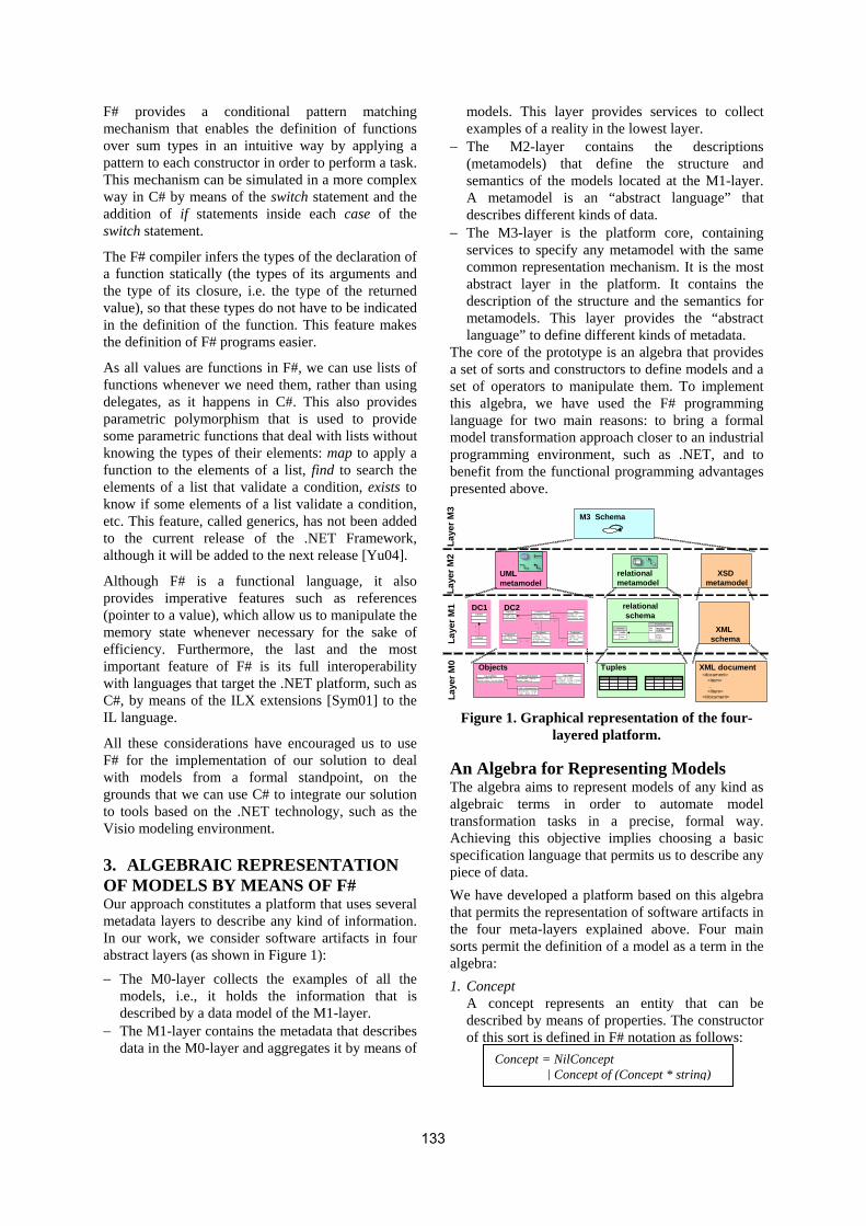
F# provides a conditional pattern matching mechanism that enables the definition of functions over sum types in an intuitive way by applying a pattern to each constructor in order to perform a task. This mechanism can be simulated in a more complex way in C# by means of the switch statement and the addition of if statements inside each case of the switch statement.
The F# compiler infers the types of the declaration of a function statically (the types of its arguments and the type of its closure, i.e. the type of the returned value), so that these types do not have to be indicated in the definition of the function. This feature makes the definition of F# programs easier.
As all values are functions in F#, we can use lists of functions whenever we need them, rather than using delegates, as it happens in C#. This also provides parametric polymorphism that is used to provide some parametric functions that deal with lists without knowing the types of their elements: map to apply a function to the elements of a list, find to search the elements of a list that validate a condition, exists to know if some elements of a list validate a condition, etc. This feature, called generics, has not been added to the current release of the .NET Framework, although it will be added to the next release [Yu04].
Although F# is a functional language, it also provides imperative features such as references (pointer to a value), which allow us to manipulate the memory state whenever necessary for the sake of efficiency. Furthermore, the last and the most important feature of F# is its full interoperability with languages that target the .NET platform, such as C#, by means of the ILX extensions [Sym01] to the IL language.
All these considerations have encouraged us to use F# for the implementation of our solution to deal with models from a formal standpoint, on the grounds that we can use C# to integrate our solution to tools based on the .NET technology, such as the Visio modeling environment.
3. ALGEBRAIC REPRESENTATION OF MODELS BY MEANS OF F# Our approach constitutes a platform that uses several metadata layers to describe any kind of information. In our work, we consider software artifacts in four abstract layers (as shown in Figure 1): − The M0-layer collects the examples of all the
models, i.e., it holds the information that is described by a data model of the M1-layer.
− The M1-layer contains the metadata that describes data in the M0-layer and aggregates it by means of
models. This layer provides services to collect examples of a reality in the lowest layer.
− The M2-layer contains the descriptions (metamodels) that define the structure and semantics of the models located at the M1-layer. A metamodel is an “abstract language” that describes different kinds of data.
− The M3-layer is the platform core, containing services to specify any metamodel with the same common representation mechanism. It is the most abstract layer in the platform. It contains the description of the structure and the semantics for metamodels. This layer provides the “abstract language” to define different kinds of metadata.
The core of the prototype is an algebra that provides a set of sorts and constructors to define models and a set of operators to manipulate them. To implement this algebra, we have used the F# programming language for two main reasons: to bring a formal model transformation approach closer to an industrial programming environment, such as .NET, and to benefit from the functional programming advantages presented above.
Figure 1. Graphical representation of the four-layered platform.
An Algebra for Representing Models The algebra aims to represent models of any kind as algebraic terms in order to automate model transformation tasks in a precise, formal way. Achieving this objective implies choosing a basic specification language that permits us to describe any piece of data. We have developed a platform based on this algebra that permits the representation of software artifacts in the four meta-layers explained above. Four main sorts permit the definition of a model as a term in the algebra: 1. Concept
A concept represents an entity that can be described by means of properties. The constructor of this sort is defined in F# notation as follows:
Concept = NilConcept | Concept of (Concept * string)
M3 Schema
UML metamodel
relational metamodel
XSD metamodel
Clase1
Clase2
1
*
DC1Clase1
Clase2
1
*
DC1-c odigo : int-fecha : Date
Factura-descripcion : string-horas : float
LineaFactu ra-codigo : int-descriptor : string-precio/hora : f loat
Tarea
-dni : string-nombre : st ring
Propietario -codigo : int-situacion : string-desc ripcion : string-tamaño : float
Propiedad-codigo : int-nom bre : str ing-dni : st ring-telefono : str ing
Trabajador
1 *0. .* 1
0..*
1..*
0..*
1
1 0..*
DC2-c odigo : int-fecha : Date
Factura-descripcion : string-horas : float
LineaFactu ra-codigo : int-descriptor : string-precio/hora : f loat
Tarea
-dni : string-nombre : st ring
Propietario -codigo : int-situacion : string-desc ripcion : string-tamaño : float
Propiedad-codigo : int-nom bre : str ing-dni : st ring-telefono : str ing
Trabajador
1 *0. .* 1
0..*
1..*
0..*
1
1 0..*
DC2
Inv o ice
P K code
da te
Invo iceLine
P K in vo ice_co deP K n um ber
p rice h oursFK 1 c ode
relationalschema
XML schema
cod igo : i nt = 0fecha : D ate = 01/12 /2004
F1 : Facturadescripcion : string = ""ho ras : floa t = 2
LF1 : L ineaFactu ra
descripcion : stringhoras : float = 2,5
LF2 : L ineaFactura
cod igo : int = 002descriptor : string = podaprecio /hora : floa t = 7
T1 : Tarea
Objects Tuples XML document
Laye
r M3
Laye
r M2
Laye
r M1
Laye
r M0
<document><item>…</item>
</document>
133

where NilConcept represents a null concept term; the first argument of the constructor Concept is a term of the sort Concept that represents its metaconcept in the next upper abstraction layer, and the second argument is its identifier.
2. Property A property is a relationship that relates either a concept or a property (subject of the property) to a concept (the object of the property), following the RDF philosophy to describe metadata [W3C]. Such relationships are specified by means of the Property sort.
We express the constructor of this sort in F# notation as follows:
where NilProperty represents the null property term and the arguments of the constructor Property are the following elements in order of appearance:
− Parent property indicating its type. − Identifier of the property. − Minimum cardinality of the property that
indicates the minimum amount of instances of the range concept, which must be related to the subject node.
− Maximum cardinality of the property that indicates the maximum amount of instances of the range concept that can be related to the subject node.
− Subject element that receives the property. This can be a concept or another property, because a property may involve other properties.
− Object element that constitutes the value of the property. A property cannot be the object of another property on the grounds that it does not provide additional information.
3. Schema In our context, a schema term represents a collection of concepts and properties that describe such concepts.
4. Level A level term represents a layer in the platform. Four terms of this sort constitute the four-layer structure of the platform. The term M3-layer represents the most abstract layer in the platform and contains a basic vocabulary to define metamodels at the M2-layer, i.e. a simplified meta-metamodel. This schema contains the term Concept and the term Property; the latter relates two concept terms, constituting the minimal structure that we use to represent a model at a lower layer. The four layers of the platform are defined as values that can be accessed by means of references (pointers to a value). This simplifies
the definition of transformation rules and enhances efficiency.
For instance, the Relational Metamodel is a schema term that contains the concepts and properties that constitute the terminology to define a relational schema, as shown in Figure 2. For instance, Table and Column are represented by means of concept terms, which are related to each other through a property table/Column in the relational metamodel at the M2-layer. This metamodel allows the definition of the concept Invoice as a table. In an identical way, the concept Code is defined as a column, which is related to the table Invoice by means of an instance of the property table/Column, i.e. by means of the invoice/Code property. Figure 2. Definition of metamodels and models on
the platform.
4. VISIO AS A VISUAL ENVIRONMENT FOR DEALING WITH ALGEBRAIC MODELS Taking into account the four-layered platform based on the functional implementation of the presented algebra, we have developed an add-in for MS Visio 2003, called Platform Integrator. This add-in permits the association of a graphic metaphor with a formal metamodel in the Visio modelling environment and the automatic definition of its models as algebraic terms. The customization of the Visio modeling visual environment is performed by means of add-ons, i.e. sets of stencils that provide the graphical information needed to define the graphical notation for a metamodel. To extend the tool, a type of module, called an add-in, is used to add functionality. Given the easy extension that such add-ins provide by means of managed COM (Component Object Model), Visio is the selected tool to embed our model repository. The formal definition of models, which our add-in provides, allows us to transform models as we present in the following section, rather than merely defining the models graphically.
Property = NilProperty | Property of (Property * string * Cardinality * Cardinality * Node * Concept)
RelationalSchema
Concept
Table Column
Invoice Code
table/Column
invoice/Code
Property
M2
M3
M1
RelationalMetamodel
is_instance_of
134
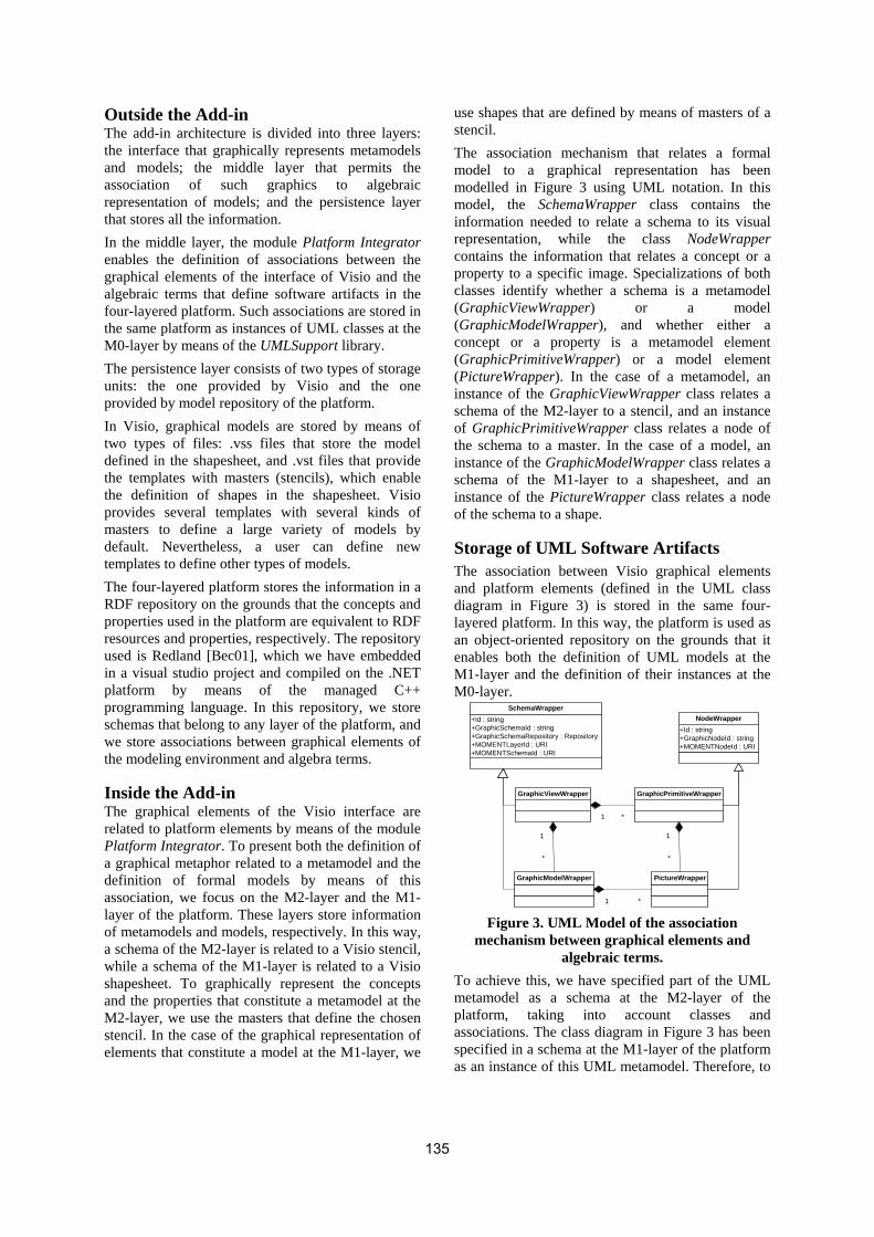
Outside the Add-in The add-in architecture is divided into three layers: the interface that graphically represents metamodels and models; the middle layer that permits the association of such graphics to algebraic representation of models; and the persistence layer that stores all the information. In the middle layer, the module Platform Integrator enables the definition of associations between the graphical elements of the interface of Visio and the algebraic terms that define software artifacts in the four-layered platform. Such associations are stored in the same platform as instances of UML classes at the M0-layer by means of the UMLSupport library. The persistence layer consists of two types of storage units: the one provided by Visio and the one provided by model repository of the platform. In Visio, graphical models are stored by means of two types of files: .vss files that store the model defined in the shapesheet, and .vst files that provide the templates with masters (stencils), which enable the definition of shapes in the shapesheet. Visio provides several templates with several kinds of masters to define a large variety of models by default. Nevertheless, a user can define new templates to define other types of models. The four-layered platform stores the information in a RDF repository on the grounds that the concepts and properties used in the platform are equivalent to RDF resources and properties, respectively. The repository used is Redland [Bec01], which we have embedded in a visual studio project and compiled on the .NET platform by means of the managed C++ programming language. In this repository, we store schemas that belong to any layer of the platform, and we store associations between graphical elements of the modeling environment and algebra terms.
Inside the Add-in The graphical elements of the Visio interface are related to platform elements by means of the module Platform Integrator. To present both the definition of a graphical metaphor related to a metamodel and the definition of formal models by means of this association, we focus on the M2-layer and the M1-layer of the platform. These layers store information of metamodels and models, respectively. In this way, a schema of the M2-layer is related to a Visio stencil, while a schema of the M1-layer is related to a Visio shapesheet. To graphically represent the concepts and the properties that constitute a metamodel at the M2-layer, we use the masters that define the chosen stencil. In the case of the graphical representation of elements that constitute a model at the M1-layer, we
use shapes that are defined by means of masters of a stencil. The association mechanism that relates a formal model to a graphical representation has been modelled in Figure 3 using UML notation. In this model, the SchemaWrapper class contains the information needed to relate a schema to its visual representation, while the class NodeWrapper contains the information that relates a concept or a property to a specific image. Specializations of both classes identify whether a schema is a metamodel (GraphicViewWrapper) or a model (GraphicModelWrapper), and whether either a concept or a property is a metamodel element (GraphicPrimitiveWrapper) or a model element (PictureWrapper). In the case of a metamodel, an instance of the GraphicViewWrapper class relates a schema of the M2-layer to a stencil, and an instance of GraphicPrimitiveWrapper class relates a node of the schema to a master. In the case of a model, an instance of the GraphicModelWrapper class relates a schema of the M1-layer to a shapesheet, and an instance of the PictureWrapper class relates a node of the schema to a shape.
Storage of UML Software Artifacts The association between Visio graphical elements and platform elements (defined in the UML class diagram in Figure 3) is stored in the same four-layered platform. In this way, the platform is used as an object-oriented repository on the grounds that it enables both the definition of UML models at the M1-layer and the definition of their instances at the M0-layer.
Figure 3. UML Model of the association mechanism between graphical elements and
algebraic terms. To achieve this, we have specified part of the UML metamodel as a schema at the M2-layer of the platform, taking into account classes and associations. The class diagram in Figure 3 has been specified in a schema at the M1-layer of the platform as an instance of this UML metamodel. Therefore, to
+Id : string+GraphicSchemaId : string+GraphicSchemaRepository : Repository+MOMENTLayerId : URI+MOMENTSchemaId : URI
SchemaWrapper
+Id : string+GraphicNodeId : string+MOMENTNodeId : URI
NodeWrapper
1 *
GraphicViewWrapper GraphicPrimitiveWrapper
GraphicModelWrapper PictureWrapper
1 *
1
*
1
*
135

define associations between elements of the platform and Visio graphical elements, a schema can be defined at the M0-layer of the platform by instantiating the classes that constitute the model at the M1-layer.
Definition of Graphic Metaphors for Metamodels To define a metamodel by means of Visio, we associate a schema of the M2-layer of the platform to a stencil. Then, each of its masters is related to a node of the schema by means of the interface in Figure 4, completing the graphical metaphor related to the metamodel. The formal metamodel can be directly defined on the platform by means of the Visio interface; it can also be loaded from the platform. To define a master in the interface shown in the Figure, an association between a metamodel of the platform and a stencil must be selected. Then, a master of the stencil and a node of the schema are selected and related by means of a new association. After this, the hidden properties of a node (i.e. the properties that are not related to a master directly) can be accessed. They are shown in the list that appears at the bottom of the interface, and they can also be navigated recursively by means of the tree, placed on the left part of the interface. Once a metamodel is graphically defined in Visio, it can be used to define visual models by means of the drag-and-drop mechanism, by dropping masters of the stencil onto the shapesheet. We enrich this mechanism so that the shape is not only graphically defined in the shapesheet but also its contents are defined in the platform. This functionality is embedded in the Platform Integrator module, providing this functionality automatically in a transparent manner to the user. Thereby, we not only define a graphical model but also provide the semantic information related to a metamodel.
Therefore, we can define formal models in a visual manner so that they can be manipulated by means of transformations as we explain in Section 5.
5. TRANSFORMATIONS The operator generate permits the translation of a model of a specific metamodel into a model of a different metamodel. The semantics of the operator is defined denotationally by means of the pattern matching mechanism of F#. The operation generate defines an evaluation strategy operationally (by means of the pattern matching mechanism) in order to enable the definition of transformation rules in a declarative manner. In this way, transformation rules are defined like axioms that do not take into account the rule evaluation strategy embedded in the operator generate. In this section, we introduce the likeness relation2, which enables the definition of transformation rules based on metamodels. Then, we describe the structure of a transformation rule. Finally, we define the operational semantics of the operator generate.
Semantical Relationships between Metamodels In our approach, transformations are based on metamodels. Applying a transformation to a source model involves two metamodels: a source metamodel that describes the structure and semantics of the source model, and a target metamodel that provides the structure and semantics for the new model to be generated. Two types of transformations can be distinguished taking into account the target metamodel:
2 We have chosen the name likeness instead of
equivalence, on the grounds that the equivalence relation is defined between elements of different metamodels, which cannot be equal.
Figure 4. Interface to graphically define concepts and properties of a metamodel.
136

− Intra-metamodel: when both the target and the source metamodels are the same. In this paper, we do not discuss this type of transformation.
− Inter-metamodel: when both the target and the source metamodels are different.
By basing our transformations on metamodels, we can specify them from an abstract point of view taking into account the metainformation that constitutes both the source and the target metamodels. This way, transformation rules can be viewed as patterns that can apply to any model of the source metamodel. To define such rules, we introduce the likeness relation between elements of two metamodels. The likeness relation is based on mappings between the elements of both the source and the target metamodels. A mapping is a property that is an instance of a property, called Likeness, defined at the M3-layer. A mapping relates a concept of the source metamodel to a concept of the target metamodel. For example, indicating that a Table in the relational metamodel is like a Class in the UML metamodel. A set of mappings conforms a likeness relationship indicating that the concepts, which participate in these mappings, represent a similar semantic meaning in their respective metamodels. A likeness relationship between elements of two metamodels may involve more than one element of either the source or the target metamodels. Thus, we distinguish between: − Simple likeness relationships: specified by means
of only one mapping. − Complex likeness relationships: specified by a set
of mappings involving several elements from either the source or the target metamodels. For example, to define an equivalence relationship between a foreign key of the relational metamodel and an aggregation of the UML metamodel, we have to relate the foreign key, the unique constraint and the not null value constraint concepts to the aggregation concept. This is because these three concepts of the relational metamodel provide the necessary knowledge to define an aggregation between two classes in the UML metamodel, such as the cardinalities of the aggregation.
A likeness relation between two metamodels is defined as the union of all likeness relationships established between the elements of both metamodels. As a first approach to provide cross-model semantic interoperability on the .NET platform, we only focus on simple likeness relationships.
Transformation Rules The operator generate is applied to a schema of the source metamodel and defines a new schema of the target metamodel. To achieve the transformation, this operator is based on a likeness relation defined between both the source and the target metamodels. By means of this relation, the operator knows what should be generated from a set of concepts of a source model. To process the elements of the source schema, the operator generate makes use of transformation rules defined declaratively. Each one of them is divided into two functions: a condition and a body. When a group of elements of the source model is processed, the condition checks their properties in order to select which generation function should be applied. These conditions take into account the order of precedence that exists between the concepts of a specific metamodel when this order is used to define a model. For instance, when we define a relational schema, we cannot define a column if the table that it belongs to is not defined previously. On the other hand, the body of the transformation rule involves the definition of concepts and properties in the target schema. The operator generate automatically generates models among different metamodels taking into account a set of transformation rules, which are applied following a specific evaluation strategy. The set of transformation rules is defined independently of the evaluation strategy chosen. To achieve this issue, all the transformation rules must have the same declaration so that the operator generate knows how to apply them. By declaration, we mean the declaration expression of a function in a F# interface (.mli), which involves the symbol that identifies the function value, the types of the arguments and the type of the function value (i.e. the type of the closure). Therefore, we denote the declaration expression of a function as follows: This is the value declaration inferred statically by the compiler where val is a reserved construct that indicates the declaration of a value; function_name is the symbol that identifies the function; arg1_type -> … -> argn_type are the types of the argument list of the function; and closure_type is the type of the closure (which is viewed as the type of the returned value in imperative programming). As a transformation rule is divided into a condition function and a body function, we present their declarations in the following subsections.
val function_name : arg1_type -> … -> argn_type -> closure_type
137

5.1.1 Condition function A condition function is the mechanism that indicates when a transformation rule can be applied. There is one, and only one, condition function for each function body. This means that a condition can indicate the suitability of only one transformation rule in a specific context, although many transformation rules can be applied to the same group of elements of a source model. The declaration expression for a condition function is as follows: where condition_name is a symbol that identifies the condition, the first argument is the source schema to be translated, and the second argument is the current node of the source schema to be translated. The condition function checks wheter or not the specified node validates a set of requirements in order to determine if it can be translated into the target schema by means of the body function of the transformation rule. Finally, the closure of the condition function is a Boolean value indicating the suitability of the transformation rule that contains the condition.
5.1.2 Body function The body function of a transformation rule materializes a likeness relationship, defined between elements of both the source and the target metamodels. This materialization involves both the definition of new elements into the target schema and specific mappings between the elements of the source schema, which are involved in the transformation rule. Such mappings provide support for traceability. Given a transformation process between two models, traceability [Got94] enables the identification of elements that are related by means of the application of a transformation rule and that belong to different models. Traceability support enhances mechanisms such as change propagation and round-trip between models. To explain the semantics of the operator generate, we use the generation of a UML model from a relational schema as an example. The materialization of a likeness relationship at the M1-layer (between models) is obtained by four steps, shown in Figure 5: 1. The concept is reified in its metaconcept; that is, if
the concept to be processed is the table Invoice, we obtain the metaconcepts Table of the relational metamodel.
2. Once we know the corresponding metaconcept of the source metamodel, we navigate the likeness relationship that relates it to a concept of the target metamodel. In the case of a table of the Relational
Metamodel, we obtain the concept Class of the OO Metamodel.
3. The operator generate instantiates the concept of the target metamodel, which becomes a metaconcept for its instance, i.e., the concept Class of the OO metamodel becomes the metaconcept for its instance OO-Invoice. The new concept, which has been generated in the new target schema at the M1-layer, is similar to the original concept in step 1, through the likeness relationship that we have defined before.
4. Finally, the operator instantiates the likeness relationship defined at the M2-layer between the Metaconcept of the source Concept and the Metaconcept’ of the new generated Concept’. The instantiation defines a new mapping in the traceability schema at the M1-layer, which is a property that has the source Concept as domain and the target Concept’ as range.
Figure 5. Description of the transformation process
The declaration of a body function is as follows: where body_name is the symbol that identifies the body function, the first argument is a schema that contains the specific mappings between elements of both the source and the target models, and a node is the element of the source model to be translated. A body function knows the source and the target models by means of the mapping schema, which contains this information. The type of the closure of a body function applied to a mapping schema and a node is the unit type3. A body function carries out side effects by accessing the layers of the platform (term of type Level) by means of references to them. Although these side effects decrease the level of abstraction of our functional approach, they avoid having to pass a whole layer as an argument for each transformation rule in order to improve efficiency. Side effects 3 This type describes a set which possesses only a single
element, which is denoted by (). This means that this function simulates the notion of procedure, just as the type void does in the C language.
val condition_name : Schema -> Node -> bool
val body_name : Schema -> Node -> unit
Invoice
source model
Table
source metamodel
M2-layer
M1-layer
Class
target metamodel
likeness mapping
target model
OO-Invoicelikeness instance
mapping
traceability model
Likeness relation
generated models
➀
➁
➂
➃
138
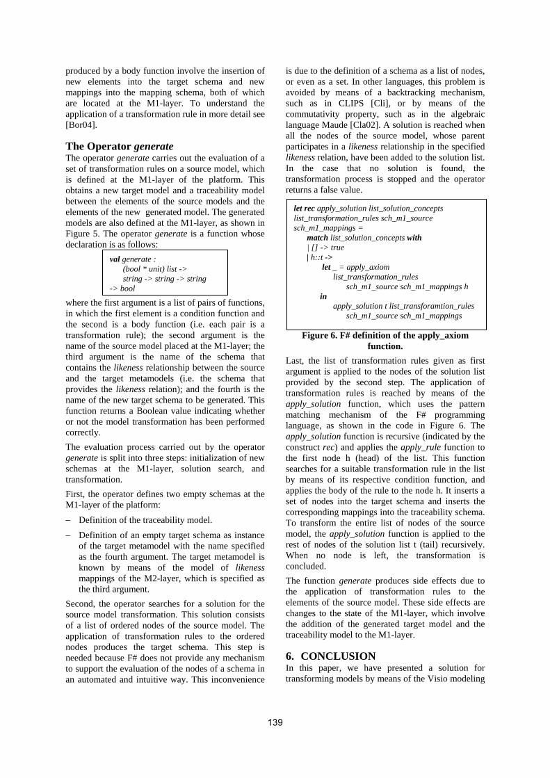
produced by a body function involve the insertion of new elements into the target schema and new mappings into the mapping schema, both of which are located at the M1-layer. To understand the application of a transformation rule in more detail see [Bor04].
The Operator generate The operator generate carries out the evaluation of a set of transformation rules on a source model, which is defined at the M1-layer of the platform. This obtains a new target model and a traceability model between the elements of the source models and the elements of the new generated model. The generated models are also defined at the M1-layer, as shown in Figure 5. The operator generate is a function whose declaration is as follows: where the first argument is a list of pairs of functions, in which the first element is a condition function and the second is a body function (i.e. each pair is a transformation rule); the second argument is the name of the source model placed at the M1-layer; the third argument is the name of the schema that contains the likeness relationship between the source and the target metamodels (i.e. the schema that provides the likeness relation); and the fourth is the name of the new target schema to be generated. This function returns a Boolean value indicating whether or not the model transformation has been performed correctly. The evaluation process carried out by the operator generate is split into three steps: initialization of new schemas at the M1-layer, solution search, and transformation. First, the operator defines two empty schemas at the M1-layer of the platform: − Definition of the traceability model. − Definition of an empty target schema as instance
of the target metamodel with the name specified as the fourth argument. The target metamodel is known by means of the model of likeness mappings of the M2-layer, which is specified as the third argument.
Second, the operator searches for a solution for the source model transformation. This solution consists of a list of ordered nodes of the source model. The application of transformation rules to the ordered nodes produces the target schema. This step is needed because F# does not provide any mechanism to support the evaluation of the nodes of a schema in an automated and intuitive way. This inconvenience
is due to the definition of a schema as a list of nodes, or even as a set. In other languages, this problem is avoided by means of a backtracking mechanism, such as in CLIPS [Cli], or by means of the commutativity property, such as in the algebraic language Maude [Cla02]. A solution is reached when all the nodes of the source model, whose parent participates in a likeness relationship in the specified likeness relation, have been added to the solution list. In the case that no solution is found, the transformation process is stopped and the operator returns a false value.
Figure 6. F# definition of the apply_axiom function.
Last, the list of transformation rules given as first argument is applied to the nodes of the solution list provided by the second step. The application of transformation rules is reached by means of the apply_solution function, which uses the pattern matching mechanism of the F# programming language, as shown in the code in Figure 6. The apply_solution function is recursive (indicated by the construct rec) and applies the apply_rule function to the first node h (head) of the list. This function searches for a suitable transformation rule in the list by means of its respective condition function, and applies the body of the rule to the node h. It inserts a set of nodes into the target schema and inserts the corresponding mappings into the traceability schema. To transform the entire list of nodes of the source model, the apply_solution function is applied to the rest of nodes of the solution list t (tail) recursively. When no node is left, the transformation is concluded. The function generate produces side effects due to the application of transformation rules to the elements of the source model. These side effects are changes to the state of the M1-layer, which involve the addition of the generated target model and the traceability model to the M1-layer.
6. CONCLUSION In this paper, we have presented a solution for transforming models by means of the Visio modeling
val generate : (bool * unit) list -> string -> string -> string -> bool
let rec apply_solution list_solution_concepts list_transformation_rules sch_m1_source sch_m1_mappings = match list_solution_concepts with | [] -> true | h::t -> let _ = apply_axiom list_transformation_rules sch_m1_source sch_m1_mappings h in apply_solution t list_transforamtion_rules sch_m1_source sch_m1_mappings
139

environment following a MDD approach. To achieve this, we built a platform that permits the definition of software artifacts following a four-layered approach, which involves metamodels and models, from an algebraic point of view. The platform provides a mechanism to transform models in a declarative way between two metamodels. This mechanism is embodied by the operator generate that receives a list of transformation rules that are applied to a source model in order to translate it into a model of a target metamodel. The application of a transformation provides support for traceability between the source model and the generated one. The platform has been implemented with the F# programming language. We have also discussed its advantages over other languages that target the .NET platform, such as C#. The platform has been integrated into the Visio modeling environment by means of an Office managed COM add-in. This allows us to deal with formal models in a visual manner through graphical metaphors. The platform also acts as a repository of formal models. This feature has been used to store the associations between the graphical elements of the Visio interface with the formal definitions stored in the platform, in a UML-based manner. To our knowledge, this is the first approach to support cross-model semantic interoperability from a modeling environment based on .NET technology.
7. ACKNOWLEDGEMENTS This work was supported by the Spanish Government under the National Program for Research, Development and Innovation, DYNAMICA Project TIC 2003-07804-C05-01, and the National Project PBC-03-00 “Methodologies of dynamic user interfaces development”.
8. REFERENCES [Bec01] Beckett, D. The Design and Implementation
of the Redland RDF Application Framework. 10th WWW Conf. May 2-5, 2001, Hong Kong.
[Bor04] Boronat, A., Ramos, I., Carsí, J. Á. Automatic Model Generation in Model Management. Springer-Verlag GMBH. Proceedings of CIT 2004. India, 2004.
[Cah00] Cahilloux, E., Manoury, P., Pagano, B.: Developing Applications With Objective Caml, Éditions O’Reilly, 2000.
[Cla02] Clavel, M., Durán, F., Eker, S., Lincoln, P., Martí-Oliet, N., Meseguer, J., Quesada, J.F. Maude: specification and programming in
rewriting logic. Theoretical Computer Science, 285(2):187-243, 2002.
[Cli] Clips documentation. http://www.cis.ksu.edu/ VirtualHelp/Info/clips.html
[Coo04] Cook, S. Domain-Specific Modeling and Model Driven Architecture, MDA Journal, January 2004
[Cza00] Czarnecki, K. and Eisenecker, U.W. Generative Programming: Methods, Tools, and Applications. Addison Wesley, Boston, 2000.
[Cza03] Czarnecki, K., Helsen, S. Classification of Model Transformation Approaches. In Proceedings OOPSLA’03 Workshop on Generative Techniques in the Context of Model-Driven Architecture, 2003.
[Ehr85] Ehrig, H., Mahr, B.: Fundamentals of Algebraic Specification 1. Springer-Verlag Berlin Heidelberg New York Tokio (1985). ISBN: 3-540-13718-1.
[Fsh] Fsharp home page. http://research.microsoft. com/ projects/ilx/fsharp.aspx
[Got94] Gotel, O. C. Z., Finkelstein, A. C. W. An Analysis of the Requirements Traceability Problem. In Proceedings of First International Conference on Requirements Engineering (ICRE). Colorado, USA. 1994.
[Rat] Rational Rose XDE Developer. http://www-306.ibm.com/software/awdtools/developer/rosexde/
[Rea93] Reade, C. Elements of Functional Programming. Addison-Wesley, 1993.
[Sel03] Selic, B.: The Pragmatics of Model-Driven Development. IEEE Software, ISSN 0740-7459. September 2003, pp. 19-25.
[Sen03] Sendall, S., Kozaczynski, W. Model Transformation: The Heart and Soul of Model-Driven Software Development. IEEE Software. September/October 2003 (Vol. 20, No. 5), pp. 42-45.
[Sym01] Syme, D. ILX: Extending the .NET Common IL for Functional Language Interoperability. In Proceedings of Workshop Babel 01, Florence, Italy. September 2001.
[Wid04] Wideman G., Microsoft Visio 2003 Developer’s Survival Pack, 2004.
[W3C] W3C, Resource Description Framework (RDF), http://www.w3.org/RDF/
[Yu04] Yu, D., Kennedy, A., Syme, D.. Formalization of Generics for the .NET Common Language Runtime. In Proceedings of the 31st ACM SIGPLAN-SIGACT Symposium on Principles of Programming Languages (POPL), Venice, Italy, January 2004.
140

Supported by the Hungarian Ministry of Education under Grant FKFP 0018/2002
Cross-language Program Slicing in the .NET Framework
Krisztián Pócza
Eötvös Loránd University
Fac. of Informatics, Dept. of Programming Languages and
Compilers Pázmány Péter sétány 1/c.
H-1117, Budapest, Hungary
Mihály Biczó Eötvös Loránd University
Fac. of Informatics, Dept. of Programming Languages and
Compilers Pázmány Péter sétány 1/c.
H-1117, Budapest, Hungary
Zoltán Porkoláb Eötvös Loránd University
Fac. of Informatics, Dept. of Programming Languages and
Compilers Pázmány Péter sétány 1/c.
H-1117, Budapest, Hungary
ABSTRACT
Dynamic program slicing methods are very attractive for debugging because many statements can be ignored in the process of localizing a bug. Although language interoperability is a key concept in modern development platforms, current slicing techniques are still restricted to a single language. In this paper a cross-language dynamic program slicing technique is introduced for the .NET environment. The method is utilizing the CLR Debugging Services API, hence it can be applied to large multi-language applications.
Keywords Program slicing, dynamic slicing, cross-language slicing, .NET Framework
1. INTRODUCTION
At the end of the seventies, when programming languages reached the level of maturity to directly support the construction of large software systems, an urging need for the extension of debugging, reverse engineering and software maintenance capabilities emerged. Science’s answer to this challenge was program slicing [Tip95a]. The original goal of program slicing was to map mental abstractions made by programmers during debugging to a reduced set of statements in source code. As a consequence, it has always been highly desirable to integrate ‘program slicers’ with existing debugging environments.
A program slice contains all statements that might directly or indirectly affect the values of variables in a set V at a program location p. The pair C=(p,V) is usually referred to as a slicing criterion, and the
contributing statements as the program slice with respect to slicing criterion C.
Since the original article of Weiser [Wei84a], many slightly different notions and algorithms have been developed to calculate program slices. As programming languages and existing technologies evolved, new features such as procedures, pointers, polymorphism, inter-process communication capabilities were also introduced, invalidating earlier definitions.
Weiser’s original method is based on calculating consecutive sets of indirectly relevant statements based on control flow and data dependency analysis [Kri03a, Wei84a, Tip95a]. Later more advanced methods have been introduced by Ottenstein et al. calculating slices based on solving a reachability problem in the program dependency graph (PDG) [Ott84a]. A PDG is a directed graph with statements and control predicates in its vertices and edges corresponding to data and control dependences. A slicing criterion can be represented as a vertex in the PDG, and a slice with respect to this criterion contains all those vertices from which the vertex of interest can be reached.
What Weiser’s and the PDG approach have in common is that they completely rely on statically available information to calculate program slices, therefore this method is called static slicing. Static slices have been specifically proposed for
Permission to make digital or hard copies of all or part of this work for personal or classroom use is granted without fee provided that copies are not made or distributed for profit or commercial advantage and that copies bear this notice and the full citation on the first page. To copy otherwise, or republish, to post on servers or to redistribute to lists, requires prior specific permission and/or a fee.
.NET Technologies’2005 conference proceedings, ISBN 7/,75832,/0,0 Copyright UNION Agency – Science Press, Plzen, Czech Republic
141

maintenance and program understanding: one is able to use static slices to observe only parts of the program that may be relevant from one specific point of view [Bes01a]. However, making no assumptions about the program’s input has a degrading effect on the precision of the obtained slice. Besides statements that actually affected the value of the variable under consideration, those that potentially did are also included in the slice. Although obtained with relatively small effort, the main disadvantage of slicing statically is usually the size of the slice. While static slicing neglects actual program input, dynamic slicing [Agr91a, Bes01a, Tip95a, Zha03a] takes it into consideration. Static slicing can be simply thought of as a method which calculates statements possibly affecting the value of a variable of interest. The notion of dynamic slicing is much closer to running the program against a specific test case in a unit test: only dependences along a specific execution path are regarded. This approach implies that different occurrences of the same statement have to be considered. As a consequence, unlike a static (or classical) slicing criterion, a dynamic slicing criterion consists of a triple (I, o, V), where I stands for program input, o is the occurrence of a statement and V is the set of variables under consideration.
As previously mentioned, a wide range of applications of program slicing have already been studied. But the highest potential is probably in debugging applications, where dynamic slicing is of great importance. One of the emerging concepts of modern real-world software systems is that they are built of a set of modules not necessarily written in the same programming language. During the whole lifecycle of such a system new features are added regularly as new modules, and existing legacy parts can also be refactored or integrated in such a way. Therefore, given a framework that directly supports cross-language programming, one has the capability to effectively slice real-world programs.
Introduced in 2001, designed with language interoperability as the key concept in mind, the .NET Framework is a platform where not only the widely studied inter-procedural but also ‘cross-module’ and ‘cross-language’ dynamic slicing techniques can be established. A module can be thought of as the equivalent of a .NET assembly. The term ‘cross-language’ means that each assembly might be composed of source code written in a different language. One of the most promising candidates for implementing a tool with this kind of capability is the .NET Debugging Services API.
Until now, the dynamic slicing community used the Java platform as its primary environment. Many interesting approaches have already been proposed,
including slicing at bytecode level [Ume03a], bytecode transformation and JVM hacking.
However, there was no standard way to implement a debugger until Java Platform Debugger Architecture (JPDA) introduced in JDK 1.3. Besides having all primitives necessary to implement a debugger, JPDA also supports a number of debugging modes including in-process and out-of-process debugging. JPDA is an advanced API with many features similar to ones present in .NET. Since .NET was released more than five years after Java, we can rightly assume the presence of an additional set of features that could possibly support dynamic slicing.
In this paper we propose a pilot solution for cross-language dynamic slicing in the .NET Framework. Our main goal was to develop a dynamic slicing algorithm that takes advantage of the sophisticated debugging capabilities of the .NET platform. We also managed to implement a test application that is capable of dynamically slicing multi-module programs written in a C#-Visual Basic .NET mixed language environment.
2. OVERVIEW OF THE .NET ARCHITECTURE FROM THE POINT OF PROGRAM SLICING
In this section we give a brief overview of Microsoft’s .NET architecture and explain why it is a perfect candidate for cross-language dynamic program slicing. We introduce the key concepts necessary to thoroughly understand the debugging capabilities of the framework.
.NET was originally designed to replace the classical Windows Programming Interface (WIN32 API), Component Object Model (COM) technology and its Distributed version (DCOM) and also to compete with the Java platform in the enterprise sector. As such, .NET offers all advantages of Java, along with language neutrality. All .NET languages use the same fully object-oriented runtime library. The philosophy behind this idea is the observation that it is easy to learn a new programming language; the hard part is when programmers are forced to learn many different class libraries and also legacy APIs. Using .NET, one is given the freedom to choose any of the 20+ supported languages and can get on with only one common library. This makes it easy to modify, transform or even integrate legacy systems.
However, some sophisticated machinery is needed to deliver these special features. To keep things simple, we propose a bottom-up overview of the architecture.
142

The Common Language Runtime (CLR) is the managed code lattice that everything else is built on. .NET uses just-in-time (JIT) compiled bytecode similar to HotSpot mechanism in Java.
Figure 1: An assembly before and after jitting
Being also a fundamental part of the runtime’s support for multi-language features, the Common Type System (CTS) provides basic value types, reference types, type safety, objects, interfaces, and delegates. It serves as a framework that helps the establishment of cross-language interoperability and type safety along with rapid execution capabilities.
The Common Language Specification (CLS) is the smallest subset of the CTS that all languages supported by the framework need to share. For example, two .NET languages can share values of non-CLS types but there will be languages which are unable to understand them.
Figure 2: Overview of the .NET architecture
All .NET languages compile to an intermediate language code called Common Intermediate Language (CIL). The compiled code is organized into assemblies. Assemblies are portable executables - similar to dll’s - with the important difference that assemblies are populated with .NET metadata and CIL code instead of normal native code. Figure 1 illustrates the way in which assemblies are jitted.
Figure 2 shows the details of the technology we have covered so far.
Companies tend to develop their specific solutions to a given problem, build custom libraries and user interfaces for their enterprise level applications. Modules are written separately in time and space, using different tools and compilers. In a later phase they are integrated, ideally in a seamless way. Unfortunately, in practice, this is rarely the case. A multi-language development platform supporting a large number of programming languages completed with a cross language and dynamic slicing capable debugger is a large step towards automatic – or at least towards seamless system integration.
In addition, with the help of cross-language program slicers programmers are able to identify bugs more precisely and at a much earlier stage. With the help of its sophisticated, carefully designed architecture and outstanding debugging capabilities, .NET is the platform that probably most closely matches the needs. In the case of program slicing, there is a two way symbiosis. Slicing improves software quality, and improved features of platforms like .NET may simplify slicing to a level where the power of its practical application appears.
However, it is not only the technical side that might benefit from such a framework. Microsoft is devoted to satisfying scientific needs as well with Rotor. Our approach focuses mainly on the possibilities of debugging from the scientific aspect. Debuggers are not toys, they are in fact serious tools in the hand of programmers. With the advanced features of .NET, a new generation of slicing capable debuggers is closer than ever before.
3. TECHNICAL OUTLOOK
In this section we give a brief overview of the basic architecture of JPDA widely used in the Java slicing community. The advanced architecture and the success of JPDA in slicing prompted us to introduce a similar approach in the .NET environment. We intend to show how .NET Debugging Services – the .NET counterpart of JPDA - can be used to generate call trace of the program being sliced.
JPDA is a multi-layer architecture dedicated to the direct support of debugger application development. Since JPDA fits in the philosophy of Java, debuggers based on this architecture are intended to run on a variety of physical platforms, virtual machines and also JDKs.
BCL
CTS (CLS)
CLR
Base Class Library
Common Type System Common Language Spec.
Common Language Runtime
Before JIT After JIT
Stub code
Object code
CIL
143

The main three layer of JPDA are:
1. Java Virtual Machine Debug Interface (JVMDI): all debugging services provided by the VM
2. Java Debug Wire Protocol (JDWP): specifies communication standards between the debugger and the process being debugged
3. Java Debug Interface (JDI): the top level interface for debugger developers.
JVMDI is the lowest layer of JPDA. It exposes both state inspection and controlling capabilities of applications running in a virtual machine to debugger developers. Basically, JVMDI is an event-driven interface. However, it has also indirect controlling capabilities totally independent of events. Default JVMDI clients are in-process, that is they run in the same virtual machine as the application that is being debugged. On the other hand, the framework also contains higher-level, out-of-process debugger interfaces.
JDWP is a communication protocol between the virtual machine being debugged and the debugger process. This protocol ensures that a single debugger is able to work either locally or (in a distributed way) on a remote computer. A very important aspect of JDWP is it independence of transport mechanisms. Every different JDWP implementation might employ different transport techniques through a simple API.
JDI is the highest level JPDA interface providing information that is of great importance in case of debuggers and also other tools that need access to the running state of a virtual machine.
In the Microsoft world, with the release of .NET, a new Debugging API and scripting strategy has also been introduced. Script engines can now compile or interpret code for the Microsoft Common Language Runtime (CLR) instead of integrating debugging capabilities directly into applications through Active Scripting [Pell]. .NET Debugging Services is not only able to debug every code compiled to IL written in any high level language, but it also provides debugging capabilities for all modern languages.
The CLR supports two types of debugging modes: in-process and out-of-process. In-process debuggers are used for inspecting the run-time state of an application and for collecting profiling information. These kinds of debuggers do not have the ability to control the process or handle events like stepping, breakpoints, etc.
Out-of-process debuggers run in a separately process providing common debugger functionality.
The CLR Debugging Services are implemented as a set of some 70+ COM interfaces, which include the design-time application, the symbol manager, the publisher and the profiler.
Figure 3: CLR Debugging architecture
The design-time interface is responsible for handling debugging events. It is implemented separated from the CLR while the host application must reside in a different process. The application is interpreted by a script and has a separate thread for receiving debugger events that run in the context of the debugged application. When a debug event occurs (assembly loaded, thread started, breakpoint reached, etc.) the application halts and the debugger thread notifies the debugging service through callback functions.
The symbol manager is responsible for interpreting the program database (PDB) files that contain data used to describe code for the modules being executed. The debugger also uses assembly metadata that also holds useful information from the point of debugging. The PDB files contain debugging information and are generated only when the compiler is explicitly forced to do so. Besides enabling the unique identification of program elements like classes, functions, variables and statements, the metadata and the program database can also be used to retrieve their original position in the source code.
The publisher is responsible for enumerating all running managed processes in the system.
The profiler tracks application performance and resources used by running managed processes.
The CLR Debugging Services API called ICorDebug [Stall] is implemented by COM interfaces. It can be directly reached from managed or unmanaged code but there are also higher level managed wrapper classes used by MDbg [Stall]. Using these interfaces we can start a process for debugging and register our managed or unmanaged callback functions. As
Symbol Manager
Design time
CLR Publisher
Profiler
144
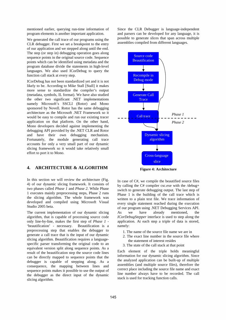
mentioned earlier, querying run-time information of program elements is another important application.
We generated the call trace of our programs using the CLR debugger. First we set a breakpoint to the entry of our application and we stepped along until the end. The step (or step in) debugging operation goes along sequence points in the original source code. Sequence points which can be identified using metadata and the program database divide the statements in high-level languages. We also used ICorDebug to query the function call stack at every step.
ICorDebug has not been standardized yet and it is not likely to be. According to Mike Stall [Stall] it makes more sense to standardize the compiler’s output (metadata, symbols, IL format). We have also studied the other two significant .NET implementations namely Microsoft’s SSCLI (Rotor) and Mono sponsored by Novell. Rotor has the same debugging architecture as the Microsoft .NET Framework so it would be easy to compile and run our existing tracer application on that platform. On the other hand, Mono developers decided against implementing the debugging API provided by the .NET CLR and Rotor and have their own debugging mechanism. Fortunately, the module generating call trace accounts for only a very small part of our dynamic slicing framework so it would take relatively small effort to port it to Mono.
4. ARCHITECTURE & ALGORITHM
In this section we will review the architecture (Fig. 4) of our dynamic slicing framework. It consists of two phases called Phase 1 and Phase 2. While Phase 1 executes mainly preprocessing steps, Phase 2 runs the slicing algorithm. The whole framework was developed and compiled using Microsoft Visual Studio 2005 beta.
The current implementation of our dynamic slicing algorithm, that is capable of processing source code only line-by-line, makes the first step of Phase 1 - ‘beautification’ - necessary. Beautification is a preprocessing step that enables the debugger to generate a call trace that is the input of our dynamic slicing algorithm. Beautification requires a language- specific parser transforming the original code to an equivalent version split along sequence points. As a result of the beautification step the source code lines can be directly mapped to sequence points that the debugger is capable of stepping along. As a consequence, the mapping between lines and sequence points makes it possible to use the output of the debugger as the direct input of the dynamic slicing algorithm.
Since the CLR Debugger is language-independent and parsers can be developed for any language, it is possible to generate slices that span across multiple assemblies compiled from different languages.
Figure 4: Architecture
In case of C#, we compile the beautified source files by calling the C# compiler csc.exe with the /debug+ switch to generate debugging output. The last step of Phase 1 is the building of the call trace which is written to a plain text file. We trace information of every single statement reached during the execution of our program using .NET Debugging Services API. As we have already mentioned, the ICorDebugStepper interface is used to step along the application. At each step a triple of data is stored, namely:
1. The name of the source file name we are in 2. The exact line number in the source file where
the statement of interest resides 3. The state of the call stack at that point
Each element of the triple holds meaningful information for our dynamic slicing algorithm. Since the analyzed application can be built-up of multiple assemblies (and multiple source files), therefore the correct place including the source file name and exact line number always have to be recorded. The call stack is used for tracking function calls.
Source code Beautification
Recompile in Debug mode
Generate Call Trace
Call trace
Dynamic slicing algorithm
Cross-language
slice
Phase 1
Phase 2
145

Phase 2 first loads the call trace file produced in Phase 1. A typical call trace can be seen in Listing 1.
Although in a real application we store fully qualified names, for the sake of clarity we have used abbreviations in Listing 1, so M stands for MainNameSpace.MainClass.Main, R for MainNameSpace.MainClass.RecursiveProdSum, A for OtherModule.Functions.Add and P for Prod.
Listing 1: Call Trace
A screenshot of the framework with source code corresponding to the call trace in Listing 1 can be seen in Figure 6.
The next step is to parse traced source files for every assembly in the program. We use here the same parser as in the beautification step. Being similar to existing dynamic slicing algorithms in this aspect [Bes01a, Xu01a, Zha03a], our approach also necessitates storing referenced and defined variables at every statement. The main task of the parser is to collect referenced and defined variables at every statement. This is illustrated in the following code fragment.
Listing 2: Simple C# code fragment
Line 2 defines variable i, line 5 references i and n, line 7 defines sum and references sum and i, line 11 references sum.
While parsing source files, a Control Dependence Graph (CDG) [Kri03a] is also created. Control dependence describes the ability of a program statement to affect the execution of another program
statement. If node m is control dependent on node n it means that there is an edge from n to m. Figure 5 illustrates the CDG of the code fragment given in Listing 2.
Listing 3: Intra-procedural version of our dynamic slicing algorithm
For example, nodes 1, 2, 3, 4, 5, 11 and 7, 8, 9 are neighbors; 7, 8, 9 are control dependent on 5.
The call trace for our example program is the following in regular expression style: "1,2,3,4(,5,7,8,9){n},5,11". The slicing criterion is (<n=2>, 111, {sum}).
According to the definition given in Section 1, <n=2> is the current program input, 111 denotes the first
idx01: MainClass.cs 10 M idx02: MainClass.cs 11 M idx03: MainClass.cs 12 M idx04: MainClass.cs 13 M idx05: MainClass.cs 14 M idx06: MainClass.cs 20 M,R idx07: MainClass.cs 22 M,R idx08: Functions.cs 10 M,R,A idx09: Functions.cs 11 M,R,A idx10: MainClass.cs 23 M,R idx11: Functions.cs 15 M,R,P idx12: Functions.cs 16 M,R,P idx13: MainClass.cs 24 M,R idx14: MainClass.cs 25 M,R idx15: MainClass.cs 20 M,R,R …
loopcond← ∅ varstore← ∅ foreach var∈{slicing_crit_vars} loop varstore←varstore∪ (var,Ref) end foreach foreach stmt in {backward call trace} do if stmt is Assignment then found:= false foreach var∈{stmt.definedvars} do if (var,Ref)∈varstore then varstore[(var,Ref)]←(var,Def) found:= true end if end foreach if found then slice:=slice∪ {stmt} addToVarStoreAndLoopCond(stmt) end if else if stmt is control statement then if stmt∈loopcond then slice←slice∪ {stmt} addToVarStoreAndLoopCond(stmt) end if end if end loop proc addToVarStoreAndLoopCond(stmt) foreach var∈{stmt.referencedvars} do varstore←varstore∪ (var,Ref) end foreach foreach parstmt in {stmt.parents} do loopcond←loopcond∪ parstmt end foreach end proc 1 int n = askUser(); 2 int i = 0; 3 int sum = 0; 4 int prod = 1; 5 while (i < n) 6 { 7 sum += i; 8 prod *= i; 9 i++; 10 } 11 Console.WriteLine(sum);
146
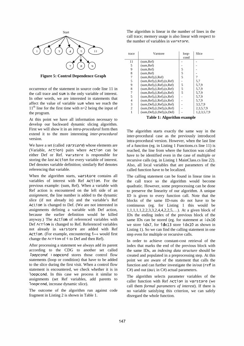
Figure 5: Control Dependence Graph
occurrence of the statement in source code line 11 in the call trace and sum is the only variable of interest. In other words, we are interested in statements that affect the value of variable sum when we reach the 11th line for the first time with n=2 being the input of the program.
At this point we have all information necessary to develop our backward dynamic slicing algorithm. First we will show it in an intra-procedural form then extend it to the more interesting inter-procedural version.
We have a set (called varstore) whose elements are (Variable, Action) pairs where Action can be either Def or Ref. Varstore is responsible for storing the last Action for every variable of interest. Def denotes variable definition; similarly Ref denotes referencing that variable.
When the algorithm starts, varstore contains all variables of interest with Ref Action. For the previous example: (sum, Ref). When a variable with Ref action is encountered on the left side of an assignment, the line number is added to the dynamic slice (if not already in) and the variable’s Ref Action is changed to Def. (We are not interested in assignments defining a variable with Def action, because the earlier definition would be killed anyway.) The Action of referenced variables with Def Action is changed to Ref. Referenced variables not already in varstore are added with Ref Action. (For example, encountering i++ would first change the Action of i to Def and then Ref).
After processing a statement we always add its parent according to the CDG to another set called loopcond. Loopcond stores those control flow statements (loop or condition) that have to be added to the slice during the first visit. When a control flow statement is encountered, we check whether it is in loopcond. In this case we process it similar to assignments (set Ref variables, add parents to loopcond, increase dynamic slice).
The outcome of the algorithm run against code fragment in Listing 2 is shown in Table 1.
The algorithm is linear in the number of lines in the call trace; memory usage is also linear with respect to the number of variables in varstore.
trace Varstore loop-cond
Slice
11 (sum,Ref) - - 5 (sum,Ref) - - 9 (sum,Ref) 5 - 8 (sum,Ref) 5 - 7 (sum,Ref),(i,Ref) 5 7 5 (sum,Ref),(i,Ref),(n,Ref) - 5,7 9 (sum,Ref),(i,Ref),(n,Ref) 5 5,7,9 8 (sum,Ref),(i,Ref),(n,Ref) 5 5,7,9 7 (sum,Ref),(i,Ref),(n,Ref) 5 5,7,9 5 (sum,Ref),(i,Ref),(n,Ref) - 5,7,9 4 (sum,Ref),(i,Ref),(n,Ref) - 5,7,9 3 (sum,Def),(i,Ref),(n,Ref) - 3,5,7,9 2 (sum,Def),(i,Def),(n,Ref) - 2,3,5,7,9 1 (sum,Def),(i,Def),(n,Def) - 1,2,3,5,7,9
Table 1: Algorithm example
The algorithm starts exactly the same way in the inter-procedural case as the previously introduced intra-procedural version. However, when the last line of a function (eg. in Listing 1 Functions.cs line 11) is reached, the line from where the function was called have to be identified even in the case of multiple or recursive calls (eg. in Listing 1 MainClass.cs line 22). Also, all local variables that are parameters of the called function have to be localized.
The calling statement can be found in linear time in the call trace so the algorithm would become quadratic. However, some preprocessing can be done to preserve the linearity of our algorithm. A unique ID is given to every function call. Note that the blocks of the same ID-runs do not have to be continuous (eg. for Listing 1 this would be 1,1,1,1,1,2,2,3,3,2,4,4,2,2,5,…). At a given block of IDs the ending index of the previous block of the same IDs can be stored (eg. for statement at idx10 we store idx7, for idx13 store idx10 as shown in Listing 1). So we can find the calling statement in one step even for multiple or recursive calls.
In order to achieve constant-cost retrieval of the index that marks the end of the previous block with the same IDs, an indexing data structure should be created and populated in a preprocessing step. At this point we are aware of the statement that calls the function and can further investigate the in/out (ref in C#) and out (out in C#) actual parameters.
The algorithm selects parameter variables of the caller function with Ref Action in varstore (we call them formal parameters of interest). If there is no variable satisfying this criterion, we can safely disregard the whole function.
Start
1 2 3 4 5
7 8 9
11
147

Listing 4: Inter-procedural slicing algorithm
Since functions can be identified based on the signature of the calling statement, formal parameters can be identified according to their order. Now we can recursively call our dynamic slicing algorithm by setting up a new varstore with all formal parameters of interest with Ref Action. When the algorithm returns to the caller we can identify all formal input parameters (nothing or ref in C#) referenced from the generated slice by checking the varstore of the called function and determine their actual parameter pairs. We consider them as referenced variables from the caller’s point of view. So they are added to the varstore with Ref Action or their Action value is changed to Ref if already in varstore. We modify loopcond in the exactly similar way as in the case of assignments and of course also add the function call to the slice.
It can be seen that we store unique varstore and loopcond information for every function call. Listing 6 shows the pseudo code of the inter-procedural version of our dynamic slicing algorithm. As its name suggests, variable callTrace stores information generated with the help of .NET Debugging Services. The algorithm walks from the end to the beginning of the call trace. Index actLine decreases at every step of the algorithm. Variable funcEnd stores the location where the currently processed function is called. If this point is reached we go back to the caller. The statements are identified by source files (which can belong to different modules) and the line number in the source file. When the algorithm detects that the execution passed the last line of a method, the source file and line number (funcEnd) are identified where the invocation of this method is performed. Actual output parameters referenced according to varstore are looked up and their formal output parameter pairs are matched. Afterwards, the dynamic slicing algorithm is called recursively.
Returning from the recursion, the referenced formal input parameters and their actual counterparts are also identified. They are added to varstore and the algorithm continues.
Function addToVarStoreAndLoopCond is almost the same presented in Listing 3 except for that loopcond and varStore are referenced by context.
5. IMPLEMENTATION
In the screen shot shown in Figure 6 we used slicing criterion (<n=42>, 151, {sum}). The example contains two files from different assemblies (MainClass is in the main module and Functions class
Function: doSliceFunction(Context context, int funcend) context.CalculateStartingVarStore() funcID:= -1; while actLine > funcEnd do begin TraceLine trace = callTrace[actLine] if funcID = -1 then funcID:= trace.FuncID //when a new function reached if trace.FuncID <> funcID then begin callPos:= rle[actRLELine].PrevBlockEnd actRLELine:= actRLELine - 1 TraceLine traceMI:= callTrace[callPos] MethodInvoke mi:= source[traceMI.src].Statement[callPos] actualParamsOut:= mi.Outputs.SelectReferenceds(context.VarStore) formalParamsOut:= mi.Actual2Formal(actualParamsOut) Context newContext:= new Context(formalParamsOut) doSliceFunction(newContext, callPos) formalParamsIn:= newContext.SelectReferenceds( mi.Parameters) if formalParamsIn.Count > 0 then begin actualParamsIn:= mi.Formal2Actual(formalParamsIn) context.VarStore.InsertThemAsRef(actualParamsIn) slice←slice ∪ {mi} foreach parstmt in {stmt.parents} do context.loopcond←context.loopcond ∪ parstmt end foreach end if actRLELine:= actRLELine — 1 actLine:= actLine - 1 continue end if //normal statement Statement stmt:= source[trace.src].Statement[trace.line] if stmt is Assignment then found:=false foreach var∈{stmt.definedvars} do if (var,Ref)∈context.VarStore then context.VarStore[(var,Ref)]←(var,Def) found:=true end if end foreach if found then slice:=slice ∪ {stmt} addToVarStoreAndLoopCond(stmt) end if else if stmt is control statement then if stmt∈context.loopcond then slice←slice ∪ {stmt} addToVarStoreAndLoopCond(stmt) end if end if actLine—- end while 148

which is used in the main module is located in another module).
In order to test the algorithm proposed earlier, we have implemented a pilot application that is capable of slicing programs that satisfy certain restrictions. These restrictions imply that the source code might contain only static functions with arbitrary program constructions (assignment, condition, loop, method invocation). The program can be built of multiple modules (assemblies) each containing multiple source files.
Since the CLR Debugger is language-independent and parsers can be developed for any language, it is possible to generate slices that cover multiple assemblies compiled from different languages. Unfortunately the only parser we have is for C#.
We used an earlier version of Marcel Debreuil’s C# source code parser library which employs the ANTLR parser generator. We compiled our
algorithm using Microsoft Visual Studio 2005 beta codenamed Whidbey.
6. CONCLUSION AND FURTHER WORK
In this paper we have shown how to utilize the .NET Debugging Services API in dynamic program slicing. Motivated by the Java Platform Debugger Architecture, our pilot solution can be effectively used to investigate dynamic dependences among modules compiled from any CLS-compliant language. We have also shown that by directly supporting cross-language programming, the .NET Framework offers significant surplus over Java.
.NET-languages, mainly C#, VB.NET and managed C++ have some very noteworthy elements such as
Figure 6: Example run of our slicing framework
149

delegates, the foreach loop, different kinds of parameter passing methods and the lock statement which justify further research related to both static and dynamic program analysis.
C# language and .NET Framework are evolving quickly. In Microsoft .NET Framework version 2.0 we intend to investigate generics, anonymous methods, partial types, yield keyword, nullable types and also some functional language implementations like Scheme [Bre04a] and Clean [Her04a].
REFERENCES
[Agr91a] H. Agrawal and J. R. Horgan. Dynamic program slicing. In SIGPLAN Notices No. 6, pages 246-256, 1990.
[Bes01a] Á. Beszédes, T. Gergely, Zs. M. Szabó, J. Csirik, T. Gyimóthy. Dynamic slicing method for maintenance of large C programs, CSMR 2001, pages 105-113.
[Bre04a] Bres,Y., Serpette,P., Serrano,M. et al. - Compiling Scheme programs to the .NET Common Intermediate Language, 2nd International Workshop on .NET Technologies, May 2004
[Her04a] Z. Hernyák, Z. Horváth, V. Zsók. Design of Language Elements for Dynamic Distributed Computation of Clean Expressions on Clusters. Submitted to TFP 2004 Fifth Symposium on Trends in Functional Programming, Ludwig-Maximilians University, Munich, Germany, 2004.
[Hor90a] S. B. Horwitz, T. W Reps, D. Binkley. Inter-procedural slicing using dependence graphs. ACM Transactions on Programming Languages and Systems, 12(1): 26-60, January 1990.
[Kri03a] J. Krinke, Advanced Slicing of Sequential and Concurrent Programs, PhD Thesis, Universität Passau, April 2003
[Mar03a] K. Maruyama, M. Terada, Timestamp Based Execution Control for C and Java Programs, AADEBUG, 2003
[Oha01a] F. Ohata, K. Hirose, M. Fujii, K. Inouse. A slicing method for object-oriented programs using lightweight dynamic information. In Proc. of the 8th Asia-Pacific Software Engineering Conference, 2001.
[Ott84a] K. J. Ottenstein, L. M. Ottenstein. The program dependence graph in software development environment. ACM SIGPLAN Notices volume 19(5), pages 177-184, 1984.
[Pel02a] M. Pellegrino. Improve Your Understanding of .NET Internals by Building a Debugger for Managed Code. MSDN Magazine, issue November 2002. http://msdn.microsoft.com/msdnmag/issues/02/11/clrdebugging/
[Rep94a] T. Reps, S. Horwiz, M. Sagiv, G. Rosay. Speeding up slicing. ACM SIGSOFT Software Engineering Notices 19, pages 11-20.
[Stall] Mike Stall’s .NET Debugging Blog, http://blogs.msdn.com/jmstall/, 2004-2005
[Tip95a] F. Tip, A survey of program slicing techniques. Journal of Programming Languages, 3(3):121-189, Sept. 1995.
[Ume03a] F. Umemori, K. Konda, R. Yokomori, K. Inoue, Design and Implementation of Bytecode-based Java Slicing System, SCAM 2003
[Wei84a] M. Weiser. Program Slicing. IEEE Transactions on Software Engineering. SE-10(4):352-357, 1984.
[Xu01a] B. Xu, Z. Chen. Dependence Analysis for Recursive Java Programs. In SIGPLAN Notices No. 12, Pages 70-76.
[Zha03a] X. Zhang, R. Gupta, Y. Zhang. Precise dynamic slicing algorithms. Proc. International Conference on Software Engineering, pages 319-329, 2003.
150

Adding Structural Reflection to the SSCLI
Francisco Ortin Jose M. Redondo Luis Vinuesa Juan M. Cueva Computer Science Department, University of Oviedo
C/Calvo Sotelo s/n, 33007, Oviedo Spain [email protected] [email protected] [email protected] [email protected]
ABSTRACT
Although dynamic languages are becoming widely used due to the flexibility needs of specific software prod-ucts, their major drawback is their runtime performance. Compiling the source program to an abstract machine’s intermediate language is the current technique used to obtain the best performance results. This intermediate code is then executed by a virtual machine developed as an interpreter. Although JIT adaptive optimizing com-pilation is currently used to speed up Java and .net intermediate code execution, this practice has not been em-ployed successfully in the implementation of dynamically adaptive platforms yet. We present an approach to improve the runtime performance of a specific set of structural reflective primitives, extensively used in adaptive software development. Looking for a better performance, as well as interaction with other languages, we have employed the Microsoft Shared Source CLI platform, making use of its JIT compiler. The SSCLI computational model has been enhanced with semantics of the prototype-based object-oriented com-putational model. This model is much more suitable for reflective environments. The initial assessment of per-formance results reveals that augmenting the semantics of the SSCLI model, together with JIT generation of native code, produces better runtime performance than the existing implementations.
Keywords Dynamic languages, structural reflection, prototype-based object-oriented computational model, Shared Source CLI, JIT code generation.
1. INTRODUCTION Since the appearance of the first abstract machine (UNCOL, 1961 [Ste61]), the notion of using the specification of a computational processor without intending to implement it (abstract machine) has been used in many different contexts [Die00]. The main objective of the UNiversal Computer Oriented Language (UNCOL) was simplifying compilers de-velopment by employing a unique universal interme-diate code.
A virtual machine involves a specific abstract ma-chine implementation. The employment of specific abstract machines implemented by different virtual machines has brought many benefits to different computing systems. The most relevant are platform neutrality (USCD P-machine [Cla82] or Forth [Moo74]), application distribution (ANDF, Architec-
ture Neutral Distribution Format [OSF91]), direct support of high-level paradigms (Smalltalk-80 [Gol-83], SECD [Lan64] or Warren Abstract Machine [War83]) and application interoperability (PVM, Parallel Virtual Machine [Sun90]).1
Despite of the many benefits obtained from using virtual machines, its main drawback has always been execution performance. Consequently, there has been considerable research aimed at improving the per-formance of virtual machine’s application execution compared to its native counterparts. Techniques like adaptive Just In Time (JIT) compilation or efficient and complex garbage collection algorithms have reached such a point that Microsoft and Sun Micro-systems identify this kind of platforms as appropriate to implement commercial applications. Nowadays, there are a lot of commercial languages and plat-forms that employ the concept of virtual machine to develop software products.
In parallel with the dominant virtual platforms (Sun’s Java Virtual Machine and Microsoft .net) and its type-safe programming languages (Java and C#), a
1 The development of is project is funded by Microsoft
Research as the second Rotor Request for Proposals, awarded in 2004.
Permission to make digital or hard copies of all or part of this work for personal or classroom use is granted without fee provided that copies are not made or distributed for profit or commercial advantage and that copies bear this notice and the full citation on the first page. To copy oth-erwise, or republish, to post on servers or to redistribute to lists, requires prior specific permission and/or a fee. .NET Technologies’2005 conference proceedings, ISBN 80-86943-01-1 Copyright UNION Agency – Science Press, Plzen, Czech Republic
151
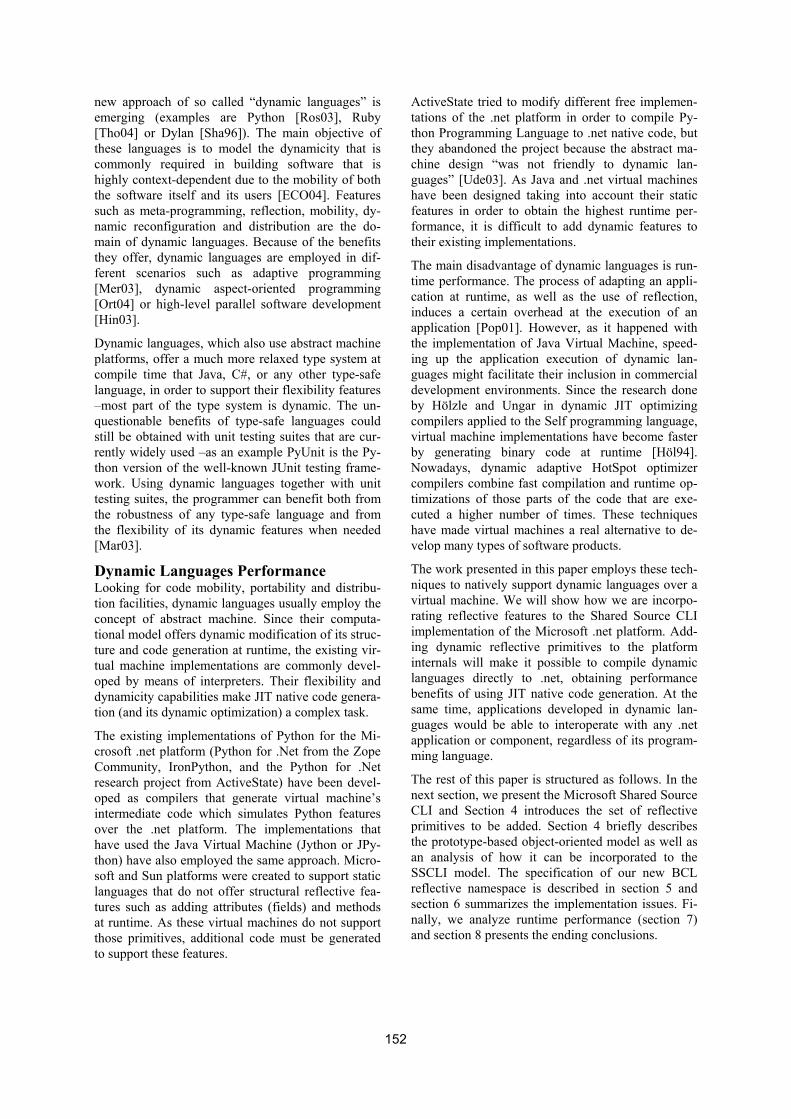
new approach of so called “dynamic languages” is emerging (examples are Python [Ros03], Ruby [Tho04] or Dylan [Sha96]). The main objective of these languages is to model the dynamicity that is commonly required in building software that is highly context-dependent due to the mobility of both the software itself and its users [ECO04]. Features such as meta-programming, reflection, mobility, dy-namic reconfiguration and distribution are the do-main of dynamic languages. Because of the benefits they offer, dynamic languages are employed in dif-ferent scenarios such as adaptive programming [Mer03], dynamic aspect-oriented programming [Ort04] or high-level parallel software development [Hin03].
Dynamic languages, which also use abstract machine platforms, offer a much more relaxed type system at compile time that Java, C#, or any other type-safe language, in order to support their flexibility features –most part of the type system is dynamic. The un-questionable benefits of type-safe languages could still be obtained with unit testing suites that are cur-rently widely used –as an example PyUnit is the Py-thon version of the well-known JUnit testing frame-work. Using dynamic languages together with unit testing suites, the programmer can benefit both from the robustness of any type-safe language and from the flexibility of its dynamic features when needed [Mar03].
Dynamic Languages Performance Looking for code mobility, portability and distribu-tion facilities, dynamic languages usually employ the concept of abstract machine. Since their computa-tional model offers dynamic modification of its struc-ture and code generation at runtime, the existing vir-tual machine implementations are commonly devel-oped by means of interpreters. Their flexibility and dynamicity capabilities make JIT native code genera-tion (and its dynamic optimization) a complex task.
The existing implementations of Python for the Mi-crosoft .net platform (Python for .Net from the Zope Community, IronPython, and the Python for .Net research project from ActiveState) have been devel-oped as compilers that generate virtual machine’s intermediate code which simulates Python features over the .net platform. The implementations that have used the Java Virtual Machine (Jython or JPy-thon) have also employed the same approach. Micro-soft and Sun platforms were created to support static languages that do not offer structural reflective fea-tures such as adding attributes (fields) and methods at runtime. As these virtual machines do not support those primitives, additional code must be generated to support these features.
ActiveState tried to modify different free implemen-tations of the .net platform in order to compile Py-thon Programming Language to .net native code, but they abandoned the project because the abstract ma-chine design “was not friendly to dynamic lan-guages” [Ude03]. As Java and .net virtual machines have been designed taking into account their static features in order to obtain the highest runtime per-formance, it is difficult to add dynamic features to their existing implementations.
The main disadvantage of dynamic languages is run-time performance. The process of adapting an appli-cation at runtime, as well as the use of reflection, induces a certain overhead at the execution of an application [Pop01]. However, as it happened with the implementation of Java Virtual Machine, speed-ing up the application execution of dynamic lan-guages might facilitate their inclusion in commercial development environments. Since the research done by Hölzle and Ungar in dynamic JIT optimizing compilers applied to the Self programming language, virtual machine implementations have become faster by generating binary code at runtime [Höl94]. Nowadays, dynamic adaptive HotSpot optimizer compilers combine fast compilation and runtime op-timizations of those parts of the code that are exe-cuted a higher number of times. These techniques have made virtual machines a real alternative to de-velop many types of software products.
The work presented in this paper employs these tech-niques to natively support dynamic languages over a virtual machine. We will show how we are incorpo-rating reflective features to the Shared Source CLI implementation of the Microsoft .net platform. Add-ing dynamic reflective primitives to the platform internals will make it possible to compile dynamic languages directly to .net, obtaining performance benefits of using JIT native code generation. At the same time, applications developed in dynamic lan-guages would be able to interoperate with any .net application or component, regardless of its program-ming language.
The rest of this paper is structured as follows. In the next section, we present the Microsoft Shared Source CLI and Section 4 introduces the set of reflective primitives to be added. Section 4 briefly describes the prototype-based object-oriented model as well as an analysis of how it can be incorporated to the SSCLI model. The specification of our new BCL reflective namespace is described in section 5 and section 6 summarizes the implementation issues. Fi-nally, we analyze runtime performance (section 7) and section 8 presents the ending conclusions.
152

2. SHARED SOURCE CLI The Microsoft SSCLI, Shared Source Common Lan-guage Infrastructure (also known as Rotor), is a source code distribution that includes fully functional implementations of both the ECMA-334 C# lan-guage standard and the ECMA-335 Common Lan-guage Infrastructure standard, various tools, and a set of libraries suitable for research purposes [Stu03]. The source code can be built and run under Windows XP, FreeBSD 4.5 or Mac OS X.
Rotor consists on 3.6 million lines of code that can be divided into 4 groups:
• The Execution Environment. This is the virtual machine of the .net platform that includes the JIT compiler, the garbage collector, the class loaders and the common type system.
• The Libraries. The SSCLI distribution includes the source code of its Base Class Library (BCL), runtime infrastructure and reflection (introspec-tion) classes, networking and XML classes, and floating point and extended array libraries.
• Compilers and Tools. Rotor includes a C# com-piler (ECMA-334) and a Jscript compiler written entirely in C#.
• Platform Abstraction Layer (PAL). This code implies the abstraction layer between the runtime environment and the operating system.
Excluding the PAL section, we have performed modifications and enhancements in every part of the Rotor structure to develop our project.
3. EXTENDING THE REFLECTIVE CAPABILITIES OF ROTOR Reflection has been recognized as a suitable tool to aid the dynamic evolution of running systems, being the primary technique to obtain the meta-programming, adaptiveness, and dynamic reconfigu-ration features of dynamic languages [Caz04]. Re-flection is the capability of a computational system to reason about and act upon itself, adjusting itself to changing conditions [Mae87]. In a reflective system, its computational domain is enhanced by its own representation, offering at runtime its structure and semantics as computable data.
The main criterion to categorize runtime reflective systems is taking into account what can be reflected. Following this classification, we can distinguish:
• Introspection: The system’s structure can be consulted but not modified. Both Java and .net platforms offer this level of reflection. By means of the java.lang.reflect package (Java) and System.Reflection namespace (.net), the pro-
grammer can get information about classes, ob-jects, methods and fields at runtime.
• Structural Reflection: The system’s structure can be modified and the changes should be reflected at runtime. An example of this kind of reflection is the Python feature of adding fields –attributes– or methods to both objects and classes.
• Computational (Behavioral) Reflection: The system semantics can be modified, changing the runtime behavior of the system. For instance, metaXa –formerly called MetaJava [Gol97]– is a Java extension that offers the programmer the ability to dynamically modify the method dis-patching mechanism. The mechanism most commonly employed in this level of reflection is Meta-Object Protocols (MOPs) [Kic91].
As mentioned above, the runtime reflective features of Rotor are restricted to the introspection level. However, the .net platform offers the facility to dy-namically generate CIL code at runtime in a limited way (it only permits to create new types, not adding new methods to the existing classes) by means of its System.Reflection.Emit namespace. Dynamic languages offer the structural level of re-flection in their computational model. This level of reflection is the one employed by dynamic languages to develop adaptive software. Much research on MOPs has revealed that computational reflection suppose a huge performance penalty in comparison with the benefits it provides [Tan03]. At the same time, many behavioral features could be simulated with structural reflection (e.g., adapting method in-vocation semantics could be substituted by a method wrapping service developed with structural reflec-tion).
Reflective Facilities We have extended the .net CLI with a set of struc-tural reflective primitives extensively used in dy-namic languages, at the abstract machine level. A new namespace has been added to the Base Class Library (BCL): System.Reflection.Structural. We will show in Section 5 which are its specific primitives, but its functionality can be grouped into:
• Attributes manipulation. It can be modified not only the structure of a class (altering the struc-ture of all of its instances), but the composition of a single object. Attributes may be added, de-leted or replaced.
• Methods manipulation. Methods of classes can be added and erased dynamically. Therefore, the set of messages accepted by an object could change at runtime depending on their dynamic
153

context. At the same time, a new method could be placed in a sole object. The body of these new methods can be obtained as copies of the existing ones, or it dynamically generated by means of the System.Reflection.Emit name-space.
The programmer could combine these facilities with the introspective services already offered by the .net platform, making the CLI an ideal system to develop language neutral adaptive software.
Conceptual Problems There exist conceptual inconsistencies between the class-based object-oriented computational model and structural reflective facilities. These inconsistencies were detected and partially solved in the field of ob-ject-oriented database management systems. In this area, objects are stored but their structure or even their types (classes) could be altered afterwards, as a result of software evolution [Ska87].
The first scenario of modifying class’s structure (at-tributes) implies updating the composition of every object that is an instance of this class. This mecha-nism was defined as schema evolution in the data-base field. The modification of class’s instances could be performed when the class is modified (ea-ger) or when the object is up to be used (lazy) [Tan89]; it is only necessary to know at runtime the class an object is instance of. The dynamic evolution of class’s methods and attributes can produce situa-tions where code access to attributes or methods that do not exist in a specific execution point; these situa-tions should be checked by a dynamic type checking mechanism, employing exception handling.
Another possibility that a reflective model supports is much more difficult to be modeled in a class-based language. How can an object's structure be modified without altering the rest of its class's instances? This problem was detected in the development of MetaXa, a reflective Java platform implementation [Gol97]. The approach they chose was the same as the
adopted by some object-oriented database manage-ment systems: schema versioning [Rod95]. A new version of the class (called “shadow” class in MetaXa) is created when one of its instances is re-flectively modified. This new class is the type of the recently customized object.
This model causes different problems such as main-taining the class data consistency, class identity, us-ing class objects in the code, garbage collection, in-heritance or memory consumption, involving a really complex implementation difficult to manage [Gol97]. One of the conclusions of their research was that the class-based object-oriented model does not fit well to structural reflective environments. They finally stated that the prototype-based model would express reflec-tive features better than class-based ones [Gol97].
4. PROTYPE-BASED OO MODEL In the prototype-based object-oriented computational model the main abstraction is the object, suppressing the existence of classes [Bor86]. Although this com-putational model is simpler than the one based on classes, there is no loss of expressiveness; i.e. any class-based program can be translated into the proto-type-based model [Ung91]. A common translation from the class-based object-oriented model is by fol-lowing the next scheme (Figure 1):
• Similar object's behavior (methods of each class) can be represented by trait objects. Their only members are methods. Thus, their derived ob-jects share the behavior they define.
• Similar object's structure (attributes of each class) can be represented by prototype objects. This object has a set of initialized attributes that represent a common structure.
• Copying prototype objects (constructor invoca-tion) is the same as creating instances of a class. A new object with a specific structure and be-havior is created.
In class-based languages where classes are first class
Point
x,y:Integer
draw()move(x,y:Integer)
point:Point
x=245y=-23
a) Class-based model b) Prototype-based model
inheritance
Prototype Cloning
Point
pointPrototype
Method implementationmove
Method implementationdraw
0y
0x
-23y
245x
point
Trait object
Prototype object
Figure 1. Translation between the class and prototype based computational model.
154

objects (Java, Smalltalk or C#), classes are repre-sented by objects at runtime (e.g., in the .net platform instances of System.Type are objects that represent classes or another type). This demonstrates that, be-sides not existing loss of expressiveness, the transla-tion of the model is intuitive and facilitates applica-tion interoperability, no matter whether the pro-gramming language uses classes or not. This is the reason why this model has been previously consid-ered as a universal substrate for object-oriented lan-guages [Wol96].
Finally, this object-oriented computational model does model structural reflective primitives in a con-sistent way –structural reflective languages such as Moostrap [Mul93] or Self [Ung87] have employed this model in a successful way [Ort05]. The proto-type-based object model overcomes the schema ver-sioning problem stated in Section 3.2. Modifying the structure (attributes as well as methods) of a single object is performed directly, because any object maintains its own structure and even its specialized behavior. As shared behavior is placed in trait ob-jects, its customization implies the adaptation of types (schema versioning).
p2
Point
pointPrototype
0y
0x
point
Method Implementationdistance
Method implementationmove
Method implementationdraw
3z
-23y
245x
methodrotate
2y
1x
Figure 2. Structural reflective modification of
objects. Figure 2 shows an example scenario. The initial point and p2 objects are clones of the pointProto-type and their shared behavior is placed in the Point trait object. A new coordinate attribute has been added only to the point object. Employing the same approach, only the p2 object is capable to rotate its coordinates. Finally, all the derived objects from the Point trait object will be able to use the new dis-tance method.
Adapting Rotor’s Computational Model We have seen how the prototype-based object-oriented model is capable of modeling structural re-flection in a coherent way. However, the .net plat-form employs a class-based model all over the CLI. Moreover, if we want to interoperate with any exist-ing .net language or application, we must follow the class-based model. Therefore, our approach consists
on continue using classes but the reflective primitives will offer a semantic of a prototype-based object model:
• As classes are first class objects in the .net plat-form, their structure is customized by means their System.Type instances. Altering their methods produces adaptation of shared behavior as if we were modifying a trait object in the pro-totype-based object model. In case we adapt at-tributes of System.Type objects, what we obtain is the customization of all the existing instances of the class adapted (schema evolution). Look-ing for a good runtime performance, we have developed a lazy schema evolution mechanism [Tan89].
• Objects are treated as prototypes. Although in the class-based object model it is not possible to add specific behavior to a single object, neither to modify its attributes without adjusting its class structure, we permit to apply these structural re-flective services to a specific class instance. Em-ploying this model, we can dynamically add or erase both methods and attributes to a specific object, overcoming the abovementioned schema versioning problem. Of course, any compiler of a statically type-checked .net language (e.g., C#) needs to be modified to make the most of these reflective features; dynamic languages will em-ploy them directly.
As an example, we show in Figure 3 a Python syn-tactic approach of a program that uses this combina-tion of the class-based and prototype-based object model, when employing the structural reflective primitives (last feature shown in the example code is not really supported by the Python programming language).
We first create a Point class with its constructor and the move and draw methods. An instance is then cre-ated (point) and a draw message passed. Then we modify the structure of a single object adding a new z attribute and its respective draw3D method. Finally, we add a new behavior to the Point class (the getX method) and a new isShowing field to every Point instance, obtaining the schema evolution mechanism previously described.
5. EXTENDING THE BCL The structural reflective features mentioned above require the enhancement of the .net platform seman-tics. We have first implemented all of them in a new namespace called System.Reflection.Structural. The primitives were initially developed in C#, mak-ing extensive use of the .net’s introspection facilities. This first implementation has empirically demon-
155

strated the viability of the proposed computational model, giving us a first assessment of performance.
class Point:"Constructor"def __init__(self, x, y):
self.x=xself.y=y
"Move Method"def move(self, relx, rely):
self.x=self.x+relxself.y=self.y+rely
"Draw Method"def draw(self):
print "("+str(self.x)+","+str(self.y)+")"
point=Point(1,2)point.draw() # (1,2)# Modify attributes of a single objectpoint.z=3print point.z # 3# Modify methods of a single objectdef draw3D(self):print "("+str(self.x)+
","+str(self.y)+","+str(self.z)+")"
point.draw3D=draw3Dpoint.draw3D() # (1,2,3)# Modify methods of a class def getX(self):return self.x
Point.getX=getXprint point.getX() # 1# Modify attributes of # every Point instancePoint.isShowing=0
Figure 3. Example Python code using structural
reflection services. This is a resume of the most significant elements we have added to the BCL (all of them, static methods of the Structural utility class):
• addMethod and removeMethod methods receive an object or class (System.Type) as a first pa-rameter indicating whether we want to modify a single object or a shared behavior. The second parameter is a MethodInfo object of the Sys-tem.Reflection namespace. This object uniquely describes the identifier, parameters, re-turn type, attributes and modifiers of a method. The user could create a new method employing the System.Reflection.Emit namespace, and add it to an object or class by means of its Meth-odInfo.
• The invoke primitive executes the method of an object or class specifying its name, return type and parameters. When the programmer uses the
invoke method to pass a message to an object, it is checked if the object has a suitable method. In case it exists, it is executed; otherwise the mes-sage is passed to its class (its trait object). A MissingMethodException is thrown if the mes-sage has not been implemented.
• The addField, getField and removeField methods are used to modify the runtime structure of single objects or their common schema (classes). If the first parameter is an object, the rest of instances of its class will not be modified. Adding a field to a class ensures that all of the existing instances contain the specified attribute; removing it guarantees that none have that at-tribute.
Employing these primitives, the code in Figure 4 shows the C# version of the Python reflective pro-gram of Figure 3. RuntimeStructuralFieldInfo rsfi = new Run-
timeStructuralFieldInfo("z", typeof(int),3, FieldAttributes.Public);
Structural.addField(point,rsfi); // Draw3D is the MethodInfo a new method // created with System.Reflection.Emit Structural.addMethod(point,draw3D); Object[] pars={}; Structural.invoke(point,draw3D.ReturnType,
"draw3D",pars); // getX is another MethodInfo object Structural.addMethod(typeof(Point),getX); Console.WriteLine(Structural.invoke(
point,getX.ReturnType,"getX",params) ); rsfi = new RuntimeStructuralFieldInfo(
"isShowing", typeof(bool),false, FieldAt-tributes.Public);
Structural.addField(typeof(Punto), rsfi);
Figure 4. C# structural reflective program. We have implemented other useful primitives such as {field, method}Exists, getFieldValue, al-
ter{Method, Field} or getMethod, as well as addi-tional classes such as RuntimeStructucturalField-Info or {Member, Method, Field}Collection. Now that we have confirmed that this set of primitives are suitable to offer the adaptable computational model presented, we are implementing part of them as an enhancement of the semantics of specific CIL in-structions. As an example, the invoke primitive should not be only part of the BCL interface; its se-mantics must also be included in the call and call-virt CIL statements. In order to achieve this func-tionality we are also modifying the semantic analysis module of the SSCLI C# compiler –it should be al-lowed to invoke non-existing methods at compile time.
6. IMPLEMENTATION The complexity of Rotor implementation prevented us from directly implementing the operations inside the runtime environment. A set of steps were defined to gradually incorporate structural reflection in Ro-
156
tor. Modifying different parts of the system one by one –from BCL to the binary code generated at run-time– has allowed us to refine the model using the experience gained.
We have divided the development process into three steps:
• Step 1: BCL-level implementation. In this step we have implemented all the reflective primi-tives in C#, making use of .net introspective ca-pabilities. The runtime environment was not modified in this step. The programmer should use all the reflective features explicitly by means of the BCL.
• Step 2: VM-level implementation. In this second step we have moved the implementation of the BCL primitives developed in the previous step to an equivalent C implementation, included into the execution environment. The BCL interface was not modified, but the implementation was included inside the virtual machine getting sig-nificantly better runtime performance. We used Rotor internal structures, data types and routines to our advantage.
• Step 3: JIT-level implementation. The final step in our development has been modifying the Ro-tor JIT code generation mechanism. We have ex-tended some CIL instruction semantics modify-ing the code generated by the JIT, in order to support structural reflection of existing .net ap-plications.
The Step 1 implementation employs a central data structure that uses four C# hash-tables to store rela-tionships between added members and their owners (either classes or instances). When accessing mem-bers, these hash-tables are consulted first and, if the member has not been reflectively added, the rest of the process continues searching in the class hierarchy using introspection. If the top of the hierarchy is reached without finding the appropriate member, a MissingMemberException is thrown. This implemen-tation is much easier than developing this code inside the runtime environment, but its execution perform-ance is significantly slower.
Once the first step was developed and tested, we pro-ceeded to include the implementation of these reflec-tive services inside the execution environment. The most important decision to be done was finding the suitable place to put the data structure that stored the reflective information. Since direct object structure manipulation turns to be much more difficult than we expected, due to its fixed-size object design, we de-cided to use each object’s Syncblock to store reflec-tive data. Thus, we assigned each object (and class) a specific structure to store its reflective information.
Although the VM-level implementation improved runtime performance considerably, reflective behav-ior must still be explicitly stated by the programmer. That is to say, it is not possible to reflectively adapt legacy .net binary code, because structural reflection must be explicitly used. We are currently working on overcoming this lack, implementing the third step of the development process.
Project Status Structural reflective primitives are being included into the CIL instruction semantics (3rd step). We have already included the attribute-manipulation ones. The new semantics has already been added to the ldfld and stfld CIL statements of the platform.
The main idea to achieve the new behavior is to modify the native code generated by the JIT com-piler. Instead of the original code that uses statically calculated member offsets, we generate a call to a helper function. This function explores the object structure in order to calculate member addresses us-ing the reflective data included in the object’s Syncblock.
Finally, we are working on modifying the JIT com-piler to support reflective manipulation of methods. Our planned implementation will generate code to a new helper function, which will return the method address (depending on the stored reflective informa-tion), performing the invocation of the returned ad-dress.
7. PRIMARY PERFORMANCE AS-SESSMENT The use of a JIT compiler in a reflectively adaptive environment could introduce performance benefits in comparison with existing interpreted-based imple-mentations. We have measured the performance of our second step implementation in comparison with four well-know Python platforms. This assessment will give us an idea of the benefits that could be ob-tained in the future.
We have measured execution time of all the primi-tives described above in loops of 10,000 iterations, removing any I/O and graphical routines [Bul00]. All tests were carried out on a lightly loaded 3.2 GHz iPIV hyper-threading system with 1 Gb of RAM run-ning WindowsXP.
The specific well-known Python implementations used in our tests were:
• CPython 2.4 (commonly referred as simply Py-thon): This is probably the most widely used Py-thon interpreted implementation; it is called CPython because it has been developed in C.
157

• ActivePython 2.4.0. Another interpreted distri-bution of Python (from ActiveState) available for Linux, Solaris and Windows.
• Jython 2.1 (formerly called JPython): A 100% pure Java implementation of the Python pro-gramming language. It is seamlessly integrated with the Java 2 Platform.
• IronPython 0.6: is a new promising implementa-tion of the Python language targeting the Com-mon Language Runtime (CLR). It compiles py-thon programs into CIL bytecodes that run on ei-ther Microsoft's .net or the Open Source Mono platform. Its current release is a pre-alpha 0.6 version. We have not used Zope’s Python for .net be-cause it is not really the same approach as Jython in Java; it provides an implementation of the Py-thon language and runtime engine in pure Java. Python for .net is not a re-implementation of Py-thon, just an integration of the existing CPython runtime with .NET. Neither have we employed ActiveState Python for .net because they have quit this research project caused by the poor per-formance results obtained [Ude03].
Table 1 shows the measurement of each primitive execution called 10,000 times, expressed in millisec-onds. As we can appreciate in this table, Jython and IronPython obtain the worst performance results in all of the tests –IronPython do not implement dele-tion of members, neither class manipulation. The requirement to implement Jython as a 100% pure Java offers a great interoperability with any Java program, but it causes a significant performance pen-alty. The same happens to IronPython: generating CIL code that simulates the Python reflective model
over a platform that does not support it produces low performance at runtime. Probably, this performance penalty is caused by the amount of extra code that must be generated to support the reflective model.
Figure 5 and Table 1 show how our BCL implemen-tation of structural reflective primitives is faster than the two systems that generate intermediate code: Jython and IronPython. Note than, since the range of values of Jython and IronPython are considerably different from the rest of implementations, we have separated both scales in Figure 5. Therefore, the val-ues of these two implementations are shown on the right of the figure, whereas the rest appear on the left. Our BCL implementation is more than 30 times faster than Jython.
0
500
1,000
1,500
2,000
2,500
3,000
3,500
4,000
4,500
1 3 5 7 9 11 13 15 17 19
Jython
IronPython
BCL
ActivePython
CPython
JIT
0
5,000
10,000
15,000
20,000
25,000
30,000
35,000
40,000
45,000
Figure 5. Execution time (milliseconds) of each
primitive over different implementations.
Primitive Jython IronPython BCL ActivePython CPython 1. Add int attributes to an object 20,679 36,032 1,632 590 5412. Add Object attributes to an object 20,290 32,013 1,762 611 5803. Add int attributes to a class 20,063 440 551 5914. Add Object attributes to a class 20,320 460 661 6105. Delete int attributes from an object 18,406 971 561 5916. Delete Object attributes from an object 19,028 961 611 6017. Delete int attributes from a class 18,536 200 540 5618. Delete Object attributes from a class 18,896 210 581 5609. Access attributes from an object 18,607 23,000 530 521 53010. Access non-existing attributes from an object 20,019 21,017 1,191 641 60111. Access attributes from a class 18,577 150 511 48112. Access non-existing attributes from a class 20,028 370 611 57113. Add methods to an object 22,592 30,230 3,364 640 48014. Add methods to a class 23,192 2,000 720 56015. Invoke methods added to an object 20,624 24,010 3,564 760 60016. Invoke non-existing methods to an object 25,276 25,567 1,840 720 80417. Invoke methods added to a class 21,064 2,680 720 68018. Delete methods added to an object 18,504 1,240 520 52019. Delete methods added to a class 18,464 280 520 520
Table 1. Measurement of 10,000 calls to each reflective primitives.
158
Figure 5 also illustrates how our system performance is not as good as the native interpreter implementa-tion (CPython and ActiveState). However, the BCL implementation is the fastest when modifying class’s structure. This is due to the laziness of the schema-evolution mechanism we have implemented.
Best results are obtained by the two platforms that interpret the Python code by means of a C implemen-tation: ActiveState and CPython. Both obtain quite similar results, which are significantly better than the BCL version when using objects –the most typical scenario– but worse when employing classes.
As we have mentioned above, we are currently in-cluding the structural reflective primitives into the JIT compiler. Although the project is still in an im-mature point to release definitive performance re-sults, we have enough information to get a first inter-esting estimation. Executing the same test suite with the new attribute semantics added to the SSCLI run-time environment, employs the 15.76% average time in comparison with the BCL version (the new im-plementation is 10.88 times better that the first one). Furthermore, the execution of JITted structural re-flective primitives requires an average of 11.58 % time in comparison with the time required in CPy-thon. Figure 5 shows these values graphically (JIT).
Although we have not developed the addition and deletion of methods in objects and classes, these first results give us an initial estimation of how the use of a JIT compiler can be employed to obtain good per-formance of runtime adaptive applications. Certainly, since we have only developed part of the reflective computational model of Python –e.g. we have not implemented the Python feature of modifying the class an object is instance of–, the results obtained could not be directly compared with execution per-formance of complete implementations of the Python programming language. What our work has revealed is that JIT compilation techniques are really appro-priate to improve the performance of adaptive sys-tems and languages. The key point is to modify the semantics of the abstract machine instead of generat-ing intermediate code that simulates this adaptive behavior. Adding this semantics at the JIT compiler level is complex task, but appears to be worth the effort.
8. CONCLUSIONS Abstract machines have been widely employed to design programming languages because of the many advantages they offer. Although performance was the main drawback in the past, modern techniques like adaptive (hotspot) Just In Time compilation have overcome this weakness. That is one of the reasons
why virtual machine platforms are nowadays com-mercially used.
Currently, due to the special flexibility and adap-tively needs of specific systems, the so called “dy-namic languages” are becoming more and more used. These languages also make use of the process of compilation to an abstract-machine’s intermediate code. However, due to the complexity of its flexible semantics, the virtual machine is commonly devel-oped as an interpreter.
Looking for better performance results, there have been different attempts to implement Python and other highly dynamic languages for.net and Java platforms. They have resulted in systems with really poor performance, so bad that they were considered unusable. Some of them have abandoned this idea. We have evaluated two, Jython and IronPython, in comparison with other two interpreted versions –CPython and ActivePython. The interpreted versions were much faster than the JIT compiled ones, when measuring their reflective features. Despite these results, we think that the use of a JIT compiler in reflective adaptive environments could obtain better performance than interpreting the intermediate lan-guage. Since Java and .net platforms have not been designed with that purpose, modifying the semantics of the abstract machine (and, therefore, the imple-mentation of the virtual machine) might produce the expected benefits.
In order to obtain a first performance assessment, we have developed a set of structural reflective primi-tives as part of the BCL .net platform. These primi-tives implement the semantics of the prototype-based object-oriented model over the SSCLI class-based platform. This first implementation obtains better performance results that generating CIL code, be-cause implies quite less code to execute at runtime.
Finally, we have performed an initial assessment of performance results obtained with the inclusion of part of the structural reflective primitives into the SSCLI runtime environment. This initial evaluation gives us an estimation of the performance benefits that will be obtained in the future, when the whole reflective semantics will be included in the code gen-erated by the JIT compiler. Although we have only added part of the reflective features of the Python programming language, the assessment presented reveals that using an adaptive-designed platform in conjunction with a JIT compiler involves important performance benefits to implement dynamic lan-guages.
9. REFERENCES [Bor86] Borning, A.H. Classes versus Prototypes in
Object-Oriented Languages. In Proceedings of
159
the ACM/IEEE Fall Joint Computer Conference, pp. 36-40, 1986.
[Bul00] Bull, J. M., Smith, L.A., Westhead, M.D., Henty, D.S., and Davey, R.A. A Benchmark Suite for High Performance Java. Concurrency: Prac-tice and Experience 12, pp. 375-388, 2000.
[Caz04] Cazzola, W., Chiba, S., and Saake, G. In ECOOP Workshop on Reflection, AOP, and Meta-Data for Software Evolution. Research Re-ports on Mathematical and Computing Sciences. Department of Mathematical and Computing Sci-ences, Tokyo Institute of Technology, 2004.
[Cla82] Clark, R., and Koehler, S. The UCSD Pascal Handbook. Prentice-Hall, Englewood Cliffs, 1982.
[Die00] Diehl, S., Hartel, P., and Sestoft, P. Abstract Machines for Programming Language Implemen-tation. Elsevier Future Generation Computer Sys-tems, Vol. 16(7), 2000.
[ECO04] ECOOP’04 Workshop on Object-Oriented Language Engineering for the Post-Java Era: Back to Dynamicity. ECOOP 2004 Workshop Reader, Lecture Notes in Computer Science, Vol. 3344, Oslo, Norway, 2004.
[Gol83] Goldberg, A., and Robson, D. Smalltalk-80, The Language and Its Implementation. Addison-Wesley, Reading, MA, 1983.
[Gol97] Golm, M., and Kleinöder, J. MetaJava - A Platform for Adaptable Operating- System Mechanisms. Lecture Notes in Computer Science 1357, Springer-Verlag, pp.507-507, 1997.
[Hin03] Hinsen, K. High-Level Parallel Software Development with Python and BSP. Parallel Processing Letters, Vol. 13, No. 3, pp. 473-484, 2003.
[Höl94] Hölzle, U., and Ungar, D. A Third-Generation Self Implementation: Reconciling Re-sponsiveness with Performance. In Proceedings of the ACM OOPSLA Conference, Portland, OR, 1994.
[Kic91] Kiczales, G. The Art of the Metaobject Pro-tocol. The MIT Press, 1991.
[Lan64] Landin, P.J. The mechanical evaluation of expressions. Computer Journal 6 (4), pp. 308-320, 1964.
[Mae87] Maes, P. Computational Reflection. PhD. Thesis, Laboratory for Artificial Intelligence, Vrije Universiteit Brussel, Belgium, 1987.
[Mar03] Martin, R.C. Are Dynamic Languages Go-ing to Replace Static Languages? Artima Devel-oper, April, 2003.
[Mer03] Mertz, D., and Simionato, M. Metaclass Programming in Python – Pushing Object-Oriented Programming to the next level. IBM de-peloperWorks. February 2003.
[Mor74] Moore, C. Forth: A new way to program a mini-computer, Astronomy & Astrophysics Sup-plement: 15, pp. 497-511, 1974.
[Mul93] Mulet, P., and Cointe, P. Definition of a Reflective Kernel for a Prototype-Based Lan-guage. In the International Symposium on Object Technologies for Advanced Software, Kanazawa (Japan), 1993.
[Ort04] Ortin, F., and Cueva, J.M. Dynamic Adapta-tion of Application Aspects. Journal of Systems and Software 71(3), pp. 229-243,2004.
[Ort05] Ortin, F., and Diez, D. Designing an Adapt-able Heterogeneous Abstract Machine by means of Reflection. Information and Software Tech-nologies 47(2), pp. 81-94, 2005.
[OSF91] Open Systems Foundation. OSF Architec-ture-Neutral Distribution Format Rationale, 1991.
[Pop01] Popovici, A., Gross, Th., and Alonso, G. Dynamic Homogenous AOP with PROSE, Tech-nical Report, Department of Computer Science, ETH Zurich, Switzerland, 2001.
[Rod95] Roddick, J. A Survey of Schema Versioning Issues for Database Systems. Information and Software Technology 37 (7), 383-393, 1995.
[Ros03] Rossum, G.V., Fred, L., and Drake, Jr. The Python Language Reference Manual. Network Theory, 2003.
[Sha96] Shalit, A., Moon, D., and Starbuck, O. The Dylan Reference Manual. Addison-Wesley, 1996.
[Ska87] Skarra, A.H., and Zdonik, S.B. Type Evolu-tion in an Object-Oriented Database. Research Directions in Object-Oriented Programming, MIT-press, pp. 393-415, 1987.
[Ste61] T.B. Steel Jr. A first version of UNCOL. In Western Joint Computing Conference, pp. 371–378. New York, 1961.
[Stu03] Stutz, D., Neward, T., and Shilling, G. Shared Source CLI Essentials. O’Reilly, 2003.
[Sun90] Sunderam, V. S. PVM: A Framework for Parallel Distributed Computing. Concurrency: Practice and Experience 2(4), pp 315-339, 1990.
[Tan89] Tan, L., and Katayama, T. Meta operations for type management in object-oriented databases - a lazy mechanism for schema evolution. In Pro-ceedings of First International Conference on Deductive and Object-Oriented Databases, DOOD, pp. 241-258. 1989.
[Tan03] Tanter, E., Noyé, J., Caromel, D., and Cointe, P. Partial behavioral reflection: spatial and temporal selection of reification. In Proceed-ings of the 18th annual ACM SIGPLAN confer-ence on Object-Oriented Programming, Systems, Languages, and Applications (OOPSLA). Cali-fornia, USA, 2003.
[Tho04] Thomas, D., Fowler, C, and Hunt, A. Pro-gramming Ruby. 2nd Edition. Addison-Wesley Professional, 2004.
160

[Ude03] Udell, J. Dynamic languages and virtual machines. InfoWorld, August, 2003.
[Ung87] Ungar, D., and Smith, R. B. SELF: The Power of Simplicity. In OOPSLA Conference Proceedings. SIGPLAN Notices, 22 (12), pp. 227-241, 1987.
[Ung91] Ungar, D., Chambers, D., Chang, B.W., and U. Hölzl. Organizing Programs without Classes.
Lisp and Symbolic Computation, Kluwer Aca-demic Publishers, pp. 223-242, 1991.
[War83] Warren, D.H.D. An abstract Prolog instruc-tion set. Technical Note 309, SRI International, Menlo Park, CA, 1983.
[Wol96] Wolczko, M., Agesen, O., and Ungar, D. Towards a Universal Implementation Substrate for Object-Oriented Languages, Sun Microsys-tems Laboratories, 1996.
161

162
To JIT or not to JIT: The Effect of Code Pitching on thePerformance of .NET Framework
David Anthony, Michael Leung and Witawas Srisa-anComputer Science and Engineering
University of Nebraska-LincolnLincoln, NE 68588
{danthony, mleung, witty}@cse.unl.edu
ABSTRACTThe .NET Compact Framework is designed to be a high-performance virtual machine for mobile and embedded de-vices that operate on Windows CE (version 4.1 and later).It achieves fast execution time by compiling methods dy-namically instead of using interpretation. Once compiled,these methods are stored in a portion of the heap calledcode-cache and can be reused quickly to satisfy future methodcalls. While code-cache provides a high-level of reusability,it can also use a large amount of memory. As a result,the Compact Framework provides a “code pitching” mech-anism that can be used to discard the previously compiledmethods as needed.
In this paper, we study the effect of code pitching on theoverall performance and memory utilization of .NET ap-plications. We conduct our experiments using Microsoft’sShared-Source Common Language Infrastructure (SSCLI).We profile the access behavior of the compiled methods.We also experiment with various code-cache configurationsto perform pitching. We find that programs can operateefficiently with a small code-cache without incurring sub-stantial recompilation and execution overheads.
Keywords: Just-in-time compilation, Java virtual ma-chines, .NET CLR, code-cache management
1. INTRODUCTIONIn both .NET and Java execution systems, Just-In-Time(JIT) compilers have been used to speed up the executiontime by compiling methods into native code for the un-derlying hardware [7, 14, 10]. JIT compilation has provedto be much more efficient than interpretation especially inexecution intensive applications [6, 7, 14, 16]. In the Mi-crosoft .NET Framework, a method is compiled prior toits first use. Afterward, the compiled methods are storedin the code-cache for future reuse [9]. This code-cache islocated in the heap region .
The size of code-cache can be increased or decreased de-pending on the program’s behavior. For example, in the
Permission to make digital or hard copies of all or part of this work forpersonal or classroom use is granted without fee provided that copies arenot made or distributed for profit or commercial advantage and that copiesbear this notice and the full citation on the first page. To copy otherwise, orrepublish, to post on servers or to redistribute to lists, requires prior specificpermission and/or a fee.
.NET Technologies’ 2005 Conference ProceedingsISBN 80-86943-01-1Copyright UNION Agency — Science Press, Plzen, Czech Republic
default configuration of the Shared-Source Common Lan-guage Infrastructure (SSCLI ) or frequently referred to asRotor, the initial code-cache size is set to 64 MB. Oncethe accumulation of compiled method reaches this size, thesystem can choose to either increase the code-cache sizeor keep the same size and free all the compiled methodsnot currently in scope (referred to as pitching) [10]. Thereare two possible overheads of the “code pitching” mecha-nism [10, 9]— the overhead of traversing through all thecompiled methods and the overhead of recompiling meth-ods after pitching. However, pitching provides a meansto maintain a small code-cache as memory is periodicallyreclaimed.
Currently, code pitching is employed in the .NET CompactFramework (CF), which is used to develop applications forsmart devices with limited memory resources [9]. Such de-vices include smart phones, Pocket PC, and embedded sys-tems running Windows CE. In these devices, a pitchingpolicy can play a very important role since it can deter-mine the amount of memory footprint for the code-cache.If pitching occurs infrequently, the code-cache would oc-cupy a large amount of memory. If pitching occurs toofrequently, a large number of methods would have to berecompiled. The goal of this paper is to take a preliminarystep to study the effect of pitching on the overall perfor-mance and memory utilization of .NET applications. Todate, there have been a few projects that investigate therecompiling decision and method unloading in Java [16,15, 3]. However, they are implemented into a virtual ma-chine that does not support pitching. With the SSCLI, wehave an opportunity to study the mechanism that has beenbuilt by a major software maker as a standard feature. Ourwork attempts to study two important research questions.They are:
RQ1: What are the basic behaviors of the compiled meth-ods?—We investigate the access behaviors, compila-tion frequency, and commonly used metrics such assize and the number of methods.
RQ2: Can we improve the overall performance and mem-ory utilization by manipulating the code-cache config-uration?—We experiment with multiple code-cachesizes and investigate the impacts of utilizing differentcache size enlargement policies.
The remainder of this paper is organized as follows. Sec-tion 2 introduces related background information. Sec-tion 3 describes our challenges and research questions indetail. It also describes the methodology and constraints
163
used to perform the experiments. Section 4 discusses theexperiments and results conducted in regards to the re-search questions. It also contains the detailed analysis ofour findings. Section 5 presents the future work. Section 7discusses prior research work in this area. The last sectionconcludes this paper.
2. BACKGROUNDThis section discusses background information related tothis work.
2.1 Shared-Source Common Language Infras-tructure (SSCLI)
The main objective of the CLI is to allow programmersto develop component-based applications where the com-ponents can be constructed using multiple languages (e.g.C#, C++, Python, etc.). ECMA-3351 (CLI) standard de-scribes “a language-agnostic runtime engine that is capableof converting lifeless blobs of metadata into self-assembling,robust, and type-safe software systems” [10]. There areseveral implementations of this standard that include Mi-crosoft’s Common Language Runtime (CLR), Microsoft’sShared Source Common Language Infrastructure (SSCLI),Microsoft’s .NET Compact Framework, Ximian’s Mono project,and GNU’s dotnet project. For this research, we use theSSCLI due to the availability of the source code. More-over, it seems to be the most mature implementation whencompared to Mono or GNU’s DotNet projects.
SSCLI is a public implementation of ECMA-335 standard.It is released under Microsoft’s shared source license. Thecode base is very similar to the commercial CLR with a fewexceptions. First, the SSCLI does not support ADO.NETand ASP.NET which are available in the commercial CLR.ADO.NET is a database connectivity API and ASP.NETis a web API that is used to create Web services. Second,the SSCLI uses a different Just-In-Time (JIT ) compilerfrom the CLR. The latter provides a more sophisticatedJIT compiler with the ability to pre-compile code. How-ever, the commercial CLR does not support code pitching.Notice that both implementations of the CLI adopt JITcompilation and not interpretation mode as in some earlierJava Virtual Machine implementations [11]. Third, it is de-signed to provide maximum portability. Thus, a softwarelayer called Portable Adaptation Layer (PAL) is used toprovide Win32 API for the SSCLI. Currently, the SSCLIhas been successfully ported to Windows, FreeBSD, andMacOS-X operating systems.
One of the major runtime components related to this workis the Just-In-Time (JIT) compiler. It is used to compilemethods within components into the native code for theunderlying hardware [14]. JIT compiler also ensures thatevery instruction conforms to the specification by ECMAstandard. Once compiled, these methods reside in the code-cache which is located in the heap memory. Instead ofrecompiling a method each time it is called, the native codeis retrieved from the code-cache [9]. When more memory isneeded by the system or when a long running applicationis moved to the background, the methods in the code-cacheare“pitched” to free up memory [9, 10].
2.2 Code Pitching MechanismThe execution engine initializes the code-cache by allocat-ing 8KB. The reserve code-cache size is set to the target
1European Computer Manufacturers Association
code-cache size which is defined by a variable. By default,this variable is set at 64MB by the SSCLI designers. Asprogram execution continues, additional heap space is al-located to the code-cache in 8KB increments as needed tostore the compiled methods. The total size of the allo-cated heap space is called the committed code-cache size.As the committed code-cache size approaches the targetcode-cache size, the allocator will decide whether to allo-cate more heap space beyond the target cache size or pitchall unused methods. The allocator will not consider codepitching until the target code-cache size, maximum cachesize or pitch trigger is reached. The default target cachesize is 64 MB whereas the maximum cache size is 2GB.
Once the target code-cache size is reached, the allocatorchooses between increasing the cache size or pitching un-used code. If the reserved size is less than the target code-cache size or the existing pitch overhead is over the accept-able maximum (default 5ms), the allocator will attempt toincrease the code-cache size. During this attempt, if thetotal needed memory is greater than the reserved size, lessthan the hard limit, not at the pitch trigger point, andpitch overhead is too high, it will expand the committedcode-cache size and the reserved size. Otherwise, it willpitch all unused code. If there is still insufficient memoryafter pitching, the code-cache size and the reserved size willbe increased until enough memory is available. If at anypoint during the execution, the number of compiled meth-ods reach the pitch trigger, pitching occurs regardless ofother cache conditions.
Currently, code pitching is used in the .NET CompactFramework which is built for embedded devices. Obviously,it is very important to strike a good balance of memory us-age and performance overhead since such devices have avery limited amount of memory. In addition, the CompactFramework is often used in Windows CE which has themaximum virtual process space of only 32 MB. Thus, theamount of code-cache has to be small enough to work inthis computing environment but yet big enough to provideefficient compilation of methods.
2.3 The DNProfilerRotor comes packaged with a sample profiler called theDNProfiler. The DNProfiler provides callbacks to the CLRallowing a user to see what is going on without havingto hard-code debug statements into the source or developcomplicated hooks. The profiler provides callbacks for shut-down and initialization, JIT events, garbage collection, thread-ing, etc... All the user has to do is provide handler codein the DNProfiler to process information during callbackevents. Once the DNProfiler is coded and compiled, theuser has to activate it by turning profiling on and settingthe profiling mask to what they want to monitor.
To gather data, the DNProfiler was modified to handle theJIT events. Specifically, the beginning and end of methodcompilation was monitored along with program initializa-tion and shutdown and pitch events. A high performancecounter was used to provide the most accurate time resultspossible.
The DNProfiler by itself cannot provide enough informa-tion to conduct our work. In order to track code-cacheusage, we also modify the JIT compiler in the section ofcode that is responsible for allocating space for compiledcode, garbage collection of unused methods, and maintain-ing the data structures representing the code-cache.
164

3. EMPIRICAL STUDYAs stated earlier, the behavior of compiled methods in.NET framework has yet to be studied. In order to de-sign an efficient pitching policy, a thorough understandingof the behavior is needed. The current lack of this knowl-edge has led us to the first research question.
RQ1: What are the basic behaviors of compiled
methods?
If a large number of methods is frequently used, then it maynot be suitable to pitch the code-cache frequently. Ourcontribution is to profile the access behavior of compiledmethod so that an efficient pitching decision can be made.We conjecture that a significant performance gain or reduc-tion in memory usage can be obtained by utilizing differentpitching policies. Thus, our second research question is:
RQ2: Can we improve the overall performance and
memory utilization by manipulating the code-
cache configuration?
In the default configuration of the SSCLI, the policy is toperform pitching as the last resort. This may not be themost optimal approach especially in the Compact Frame-work where the amount of memory available on a systemmay be limited. Our contribution is to identify a cachesize and suggest pitching policies that would result in smallcache footprint and minimal compilation overhead.
3.1 Variables and MeasuresThe JIT compiler relies on several variables to control cachesize and pitching. These variables are used to control thecompiler when to pitch, maximum and minimum cache size,and cache growth characteristics. As will be described inthe next subsection, we utilize existing experimental ob-jects written in C# to perform our experiment.
Throughout the experiment, we monitor the following vari-ables. They provided useful insight into the operation ofthe JIT compiler, specifically, its caching mechanism.
• Number of Pitch EventsWhen the compiler removes compiled code from thecache it is called a pitch event. Pitching will preservemethods that are currently in use, but will removethe rest.
• Number of RecompilationsAfter a method has been pitched, each time it hasto be complied again is called a recompilation. Amethod could be pitched and recompiled multiple times.
• Number of Different MethodsThis is the number of unique methods compiled. Thenumber of unique methods does not include recom-pilations and does not consider whether the methodhas been pitched or not.
• Committed Code-Cache SizeThe amount of heap space requested from the systemto store code is called the committed code-cache size.The compiler asks for heap in increments of 8k.
• Code-Cache UsageCode-Cache usage is the actual amount of memoryused to store compiled methods at a given time.
To address RQ1, we monitor the basic behavior of compiledmethods. Our goal is to derive at two important perfor-mance metrics based on the results of variables above:
1. compilation frequency—we monitor how often meth-ods are compiled and recompiled.
2. concentration of compiled methods—we monitor whichpart in the execution methods are compiled the most.
We also observe the average size of compiled method andcompared them to the sizes of typical objects. In orderto do our experiments, we need to create an environmentwhere the amount of memory is similar to a typical Javaembedded device. To do so, we set the initial code-cachesize to 256KB. However, we would allow the SSCLI to en-large the code-cache as necessary.
To address RQ2, we go a step further and prevent the SS-CLI from enlarging the code-cache. The goal of our experi-ment is to observe the behavior of compiled methods underhard-limit and explore different code-cache configurationsto improve the overall performance. We also compare theexecution time among different configurations that resultin different number of pitch events.
3.2 Experimental ObjectsTo address our research questions, we need a set of pro-grams that compiled a large number of methods. In addi-tion, we must be able to manipulate the way these programsare operated. As of now, there are very few benchmark pro-grams available for the .NET platform. We have gathered3 different programs that compiled a reasonable amountof methods (over 1000). We also want to observe how thecode-cache would perform during the execution of smallerapplications. Therefore, we also experiment with using theclassic HelloWorld and Adaptive Huffman Compression toget some insights on how many methods are needed to exe-cute such as simple programs. To our surprise, HelloWorldstill requires over 300 compiled methods. This section de-scribes the experimental objects:
• LCSCThis benchmark is based on the front end of a C#compiler. The program parses a given C# input filewith a generalized LR algorithm. The benchmark isavailable from Microsoft’s research web site [8], alongwith the inputs that were used in performing the anal-ysis.
• AHCThis program uses an adaptive Huffman compressionalgorithm to process files. For this program therewere three separate inputs for use as test cases. Thisbenchmark is also available from Microsoft’s researchweb site [8].
• Hello WorldThis is the classic ”Hello World” program written inC#. It simply prints ”Hello World” to the consoleand exits. Using such a simple program provided in-sight into how many methods were needed just tostart and stop program execution. The specific fileused is available in the sscli/samples/hello directory.
• CodeToHTMLCodeToHTML is an example program found in the ss-cli/samples/utilities/codetohtml directory. This pro-gram parses a given C# or Jscript file and converts
165

Application Minimum (bytes) Maximum (bytes) Average (bytes) Standard Deviation Number of MethodsLCSC 52 27024 1044.93 2587.04 1351AHC 52 6320 317.04 474.21 514
Hello World 52 6320 299.95 472.37 327CLisp 52 44008 425.66 1424.96 1168
CodeToHTML 52 44008 460.67 1543.39 1665
Table 1: Basic characteristic of the compiled methods in our benchmarks
% of space needed in the code-cacheApplication 15% 30% 45% 60% 75%
LCSC 0.65% 1.08% 1.41% 1.77% 2.16%AHC 0.03% 0.05% 0.07% 99.95% 99.96%
Hello World 19.81% 35.54% 49.28% 55.03% 79.38%CLisp 6.27% 11.58% 16.66% 40.12% 94.85%
CodeToHTML 0.08% 0.18% 0.24% 0.28% 0.33%
Table 2: Code-cache usage based on percentage of execution
it to an HTML file. The generated HTML file dis-plays formatted C# in a clearly organized manner.The test cases used were the C# files from the LCSCbenchmark and are available for download from theMicrosoft web site.
• CLisp CompilerThis is a small compiler that converts a Lisp sourcefile to an executable. The compiler was used to com-pile two sample source files, a Fibonacci series genera-tor and a numerical sorting algorithm. This compileris found in the sscli/compilers/clisp directory.
4. RESULTSIn the following subsections, we present the results of ourexperiments that answer two research questions proposedin Section 3.
4.1 RQ1: Access BehaviorIn this section, we discuss the basic behavior of these com-piled methods. The issues that will be discussed in thissection include the number of compiled methods in eachapplication, the number of methods that are recompiled,and the size of the compiled methods. Table 1 depicts thesize information of compiled methods in our benchmarkprograms.
0
20
40
60
80
100
1 2 3 4 5 6 7 8 9 10
Number of times compiled
LCSC AHC Hello World CLisp CodeToHTML
Figure 1: Distribution of compiled methods basedon the number of compilations
It is worth noticing that typical objects in Object-OrientedLanguages such as Java and C# only have the averageobject size of less than 100 bytes [4, 13]. However, theaverage size of the compiled methods in each applicationrange from 300 bytes to 1000 bytes. It is also worth notingthat the smallest size for a compiled method is 52 bytes.This is true across all applications. For the largest size,a method can be as large as 44K bytes. Since the SSCLIcommits memory in increments of 8K bytes, five requests toincrement must be made just to hold the largest compiledmethod in our applications. If no pitching is used, 1.5 MBof memory is needed to stored the compiled methods inLCSC (LCSC needs the largest amount of memory at 1.4MB).
It is also worth noticing that even small applications suchas HelloWorld, a significant number of methods is stillneeded to complete the execution (i.e. 327 methods inthis case). However, we also find that complex applica-tions such as compilers or HTML generator only requireabout 1500 methods. We suspect that both compilers andHTML generator perform repetitive routines, many of themethods can be reused over the length of execution.
In our experiment, we first study the code-cache usage ofevery application. We set the cache size to be large enoughso that pitching does not occur. With the proposed setof benchmarks, the size is set to 2 MB. We then monitorthe percentage of execution and the percentage of the con-sumption of the code-cache. For example, LCSC requires1.4 MB of space to store all compiled methods. When theprogram consumes 15% of all the needed cache space or212 KB, we observe the percentage of execution. In thiscase, the program has only completed 0.65% of the totalexecution time (see Table 2). It is worth noting that inthree out of five applications, about 50% of all the spaceneeded for the code-cache are consumed with in the firstfew percents of execution.
We also monitor the distribution of methods based on thenumber of compilations. We set the code-cache size to256KB to emulate embedded devices environment and in-duce some pitch events. We find that in two applica-tions AHC and HelloWorld, all methods are compiled onlyonce. However, in larger applications, such as compilers
166
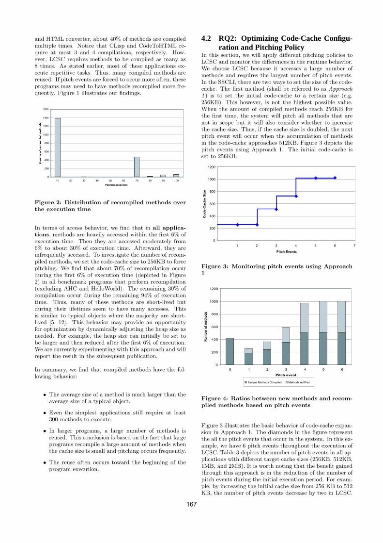
and HTML converter, about 40% of methods are compiledmultiple times. Notice that CLisp and CodeToHTML re-quire at most 3 and 4 compilations, respectively. How-ever, LCSC requires methods to be compiled as many as8 times. As stated earlier, most of these applications ex-ecute repetitive tasks. Thus, many compiled methods arereused. If pitch events are forced to occur more often, theseprograms may need to have methods recompiled more fre-quently. Figure 1 illustrates our findings.
0
200
400
600
800
1000
1200
1400
1600
10 20 30 40 50 60 70 80 90 100
Percent execution
Figure 2: Distribution of recompiled methods overthe execution time
In terms of access behavior, we find that in all applica-tions, methods are heavily accessed within the first 6% ofexecution time. Then they are accessed moderately from6% to about 30% of execution time. Afterward, they areinfrequently accessed. To investigate the number of recom-piled methods, we set the code-cache size to 256KB to forcepitching. We find that about 70% of recompilation occurduring the first 6% of execution time (depicted in Figure2) in all benchmark programs that perform recompilation(excluding AHC and HelloWorld). The remaining 30% ofcompilation occur during the remaining 94% of executiontime. Thus, many of these methods are short-lived butduring their lifetimes seem to have many accesses. Thisis similar to typical objects where the majority are short-lived [5, 12]. This behavior may provide an opportunityfor optimization by dynamically adjusting the heap size asneeded. For example, the heap size can initially be set tobe larger and then reduced after the first 6% of execution.We are currently experimenting with this approach and willreport the result in the subsequent publication.
In summary, we find that compiled methods have the fol-lowing behavior:
• The average size of a method is much larger than theaverage size of a typical object.
• Even the simplest applications still require at least300 methods to execute.
• In larger programs, a large number of methods isreused. This conclusion is based on the fact that largeprograms recompile a large amount of methods whenthe cache size is small and pitching occurs frequently.
• The reuse often occurs toward the beginning of theprogram execution.
4.2 RQ2: Optimizing Code-Cache Configu-ration and Pitching Policy
In this section, we will apply different pitching policies toLCSC and monitor the differences in the runtime behavior.We choose LCSC because it accesses a large number ofmethods and requires the largest number of pitch events.In the SSCLI, there are two ways to set the size of the code-cache. The first method (shall be referred to as Approach1 ) is to set the initial code-cache to a certain size (e.g.256KB). This however, is not the highest possible value.When the amount of compiled methods reach 256KB forthe first time, the system will pitch all methods that arenot in scope but it will also consider whether to increasethe cache size. Thus, if the cache size is doubled, the nextpitch event will occur when the accumulation of methodsin the code-cache approaches 512KB. Figure 3 depicts thepitch events using Approach 1. The initial code-cache isset to 256KB.
0
200
400
600
800
1000
1200
1 2 3 4 5 6 7
Pitch Events
Co
de-C
ach
e S
ize
Figure 3: Monitoring pitch events using Approach1
0
200
400
600
800
1000
1200
0 1 2 3 4 5 6
Pitch event
Nu
mb
er o
f m
eth
od
s
Methods reJITedUnique Methods Compiled
Figure 4: Ratios between new methods and recom-piled methods based on pitch events
Figure 3 illustrates the basic behavior of code-cache expan-sion in Approach 1. The diamonds in the figure representthe all the pitch events that occur in the system. In this ex-ample, we have 6 pitch events throughout the execution ofLCSC. Table 3 depicts the number of pitch events in all ap-plications with different target cache sizes (256KB, 512KB,1MB, and 2MB). It is worth noting that the benefit gainedthrough this approach is in the reduction of the number ofpitch events during the initial execution period. For exam-ple, by increasing the initial cache size from 256 KB to 512KB, the number of pitch events decrease by two in LCSC.
167
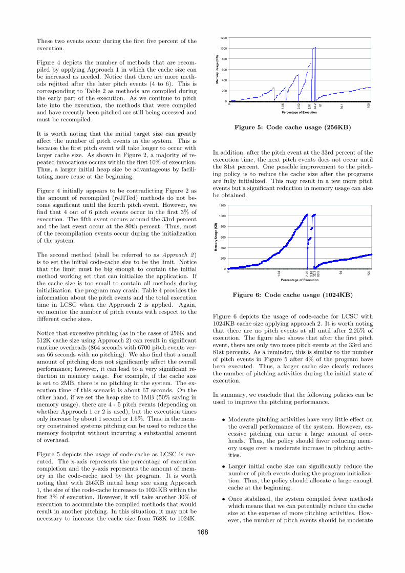
These two events occur during the first five percent of theexecution.
Figure 4 depicts the number of methods that are recom-piled by applying Approach 1 in which the cache size canbe increased as needed. Notice that there are more meth-ods rejitted after the later pitch events (4 to 6). This iscorresponding to Table 2 as methods are compiled duringthe early part of the execution. As we continue to pitchlate into the execution, the methods that were compiledand have recently been pitched are still being accessed andmust be recompiled.
It is worth noting that the initial target size can greatlyaffect the number of pitch events in the system. This isbecause the first pitch event will take longer to occur withlarger cache size. As shown in Figure 2, a majority of re-peated invocations occurs within the first 10% of execution.Thus, a larger initial heap size be advantageous by facili-tating more reuse at the beginning.
Figure 4 initially appears to be contradicting Figure 2 asthe amount of recompiled (reJITed) methods do not be-come significant until the fourth pitch event. However, wefind that 4 out of 6 pitch events occur in the first 3% ofexecution. The fifth event occurs around the 33rd percentand the last event occur at the 80th percent. Thus, mostof the recompilation events occur during the initializationof the system.
The second method (shall be referred to as Approach 2 )is to set the initial code-cache size to be the limit. Noticethat the limit must be big enough to contain the initialmethod working set that can initialize the application. Ifthe cache size is too small to contain all methods duringinitialization, the program may crash. Table 4 provides theinformation about the pitch events and the total executiontime in LCSC when the Approach 2 is applied. Again,we monitor the number of pitch events with respect to thedifferent cache sizes.
Notice that excessive pitching (as in the cases of 256K and512K cache size using Approach 2) can result in significantruntime overheads (864 seconds with 6700 pitch events ver-sus 66 seconds with no pitching). We also find that a smallamount of pitching does not significantly affect the overallperformance; however, it can lead to a very significant re-duction in memory usage. For example, if the cache sizeis set to 2MB, there is no pitching in the system. The ex-ecution time of this scenario is about 67 seconds. On theother hand, if we set the heap size to 1MB (50% saving inmemory usage), there are 4 - 5 pitch events (depending onwhether Approach 1 or 2 is used), but the execution timesonly increase by about 1 second or 1.5%. Thus, in the mem-ory constrained systems pitching can be used to reduce thememory footprint without incurring a substantial amountof overhead.
Figure 5 depicts the usage of code-cache as LCSC is exe-cuted. The x-axis represents the percentage of executioncompletion and the y-axis represents the amount of mem-ory in the code-cache used by the program. It is worthnoting that with 256KB initial heap size using Approach1, the size of the code-cache increases to 1024KB within thefirst 3% of execution. However, it will take another 30% ofexecution to accumulate the compiled methods that wouldresult in another pitching. In this situation, it may not benecessary to increase the cache size from 768K to 1024K.
0
200
400
600
800
1000
1200
0
1.0
8
2.0
2
2.9
1
33
.2 81
94
.1
10
0
Percentage of Execution
Me
mo
ry U
sa
ge
(K
B)
Figure 5: Code cache usage (256KB)
In addition, after the pitch event at the 33rd percent of theexecution time, the next pitch events does not occur untilthe 81st percent. One possible improvement to the pitch-ing policy is to reduce the cache size after the programsare fully initialized. This may result in a few more pitchevents but a significant reduction in memory usage can alsobe obtained.
0
200
400
600
800
1000
1200
0
1.0
4
2.2
5
5.9
8
80.9 94
100
Percentage of Execution
Mem
ory
Usag
e (
KB
)
32
.3
Figure 6: Code cache usage (1024KB)
Figure 6 depicts the usage of code-cache for LCSC with1024KB cache size applying approach 2. It is worth notingthat there are no pitch events at all until after 2.25% ofexecution. The figure also shows that after the first pitchevent, there are only two more pitch events at the 33rd and81st percents. As a reminder, this is similar to the numberof pitch events in Figure 5 after 4% of the program havebeen executed. Thus, a larger cache size clearly reducesthe number of pitching activities during the initial state ofexecution.
In summary, we conclude that the following policies can beused to improve the pitching performance.
• Moderate pitching activities have very little effect onthe overall performance of the system. However, ex-cessive pitching can incur a large amount of over-heads. Thus, the policy should favor reducing mem-ory usage over a moderate increase in pitching activ-ities.
• Larger initial cache size can significantly reduce thenumber of pitch events during the program initializa-tion. Thus, the policy should allocate a large enoughcache at the beginning.
• Once stabilized, the system compiled fewer methodswhich means that we can potentially reduce the cachesize at the expense of more pitching activities. How-ever, the number of pitch events should be moderate
168

Applications 256k 512k 1024k 2048k 4096k 8192k 16384k 65536kLCSC 6 4 3 0 0 0 0 0AHC 0 0 0 0 0 0 0 0
CodeToHTML 3 2 0 0 0 0 0 0Hello World 0 0 0 0 0 0 0 0
CLisp 2 1 0 0 0 0 0 0
Table 3: The number of pitch events with different code-cache sizes
Cache Approach 2 Approach 1Size Execution Time (sec) Pitches Execution Time (sec) Pitches256k 864.32 6774 68.81 6512k 412.17 1470 68.64 51024k 69.45 5 69.44 32048k 66.88 0 68.38 04096k 66.78 0 68.16 08192k 67.52 0 68.38 016384 67.59 0 67.98 065536 67.58 0 68.19 0
Table 4: The number of pitch events and execution times with Approach 2
and not result in a substantial run-time overhead.Thus, the policy should include reducing the cachesize after the initialization phase.
5. FUTURE WORKBetter benchmarks are needed that utilize more methodsthat force the execution engine to pitch more frequentlyespecially for larger cache sizes. Ideally, pitching shouldoccur with heap sizes that are close to the default targetsize. In addition, the benchmarks used in this experimentdo not demonstrate the diversity of applications the typ-ical end user runs. More practical benchmarks are defi-nitely needed to better simulate a real world system. Onthe other hand, some of the chosen experimental objectscompile reasonable amounts of methods.
With that said, many of our results derive from experiment-ing with these few benchmark programs. Thus, our con-clusions or suggestions should not be viewed as generalizedones. Instead, they should be viewed as potential solutionsto improve the performance of the code-pitching mecha-nism in the SSCLI and .NET Compact Framework. Ob-viously, experiments with more benchmark programs areneeded.
Future work will be focused on two primary goals. Thefirst goal is to develop better benchmarks in order to bet-ter simulate real world uses of the SSCLI. These bench-marks should focus on what a more average user would beexpected to run. New benchmarks should have network-ing and other communication methods that are inherent totheir proper execution.
The second major goal is to develop a better code pitchingmechanism that selectively removes code from the cache,as opposed to the all or nothing approach taken in thecurrent Rotor implementation. This improved collectionmechanism will likely correlate method usage and size toenable the pitching mechanism to make a better decisionas to its usefulness in the future. In addition, the currentRotor implementation does not decrease the size once the
code-cache has been expanded. We plan to investigate theperformance gain of decreasing the cache size after the ini-tial phase of execution.
6. RELATED WORKIn [2], multi-level recompilation technique was introducedas part of the Jalapeno Virtual Machine. The basic ideais to use non-optimized compiler to compile a method thefirst time it is called. During the execution, the virtual ma-chine would keep track of all the ”hot” methods (frequentlyaccesses) and recompile them with higher optimization lev-els.
Currently, the code pitching mechanism in .NET compactframework as well as the SSCLI discards all compiled meth-ods that are not in scope. The code-cache itself is sepa-rately compartmentalized from the main heap memory re-gion. This is different than work conducted by Zhang [16,15]. In their work, the IBM’s Research Virtual Machine(RVM) [1] was modified to incorporate code pitching. Un-like the .NET CF and the SSCLI, the RVM intermixedobjects with compiled methods and therefore, the regu-lar garbage collector is used to unload compiled methods.Their framework attempted to adaptively balance the com-pilation overhead and memory usage in the environmentwhere objects and compiled code are stored together. Theirmain strategy is to identify what to unload and when to un-load compiled methods. They reported that their strategycan reduce the code size by 43% without incurring sub-stantial overhead in memory unconstrained system. If thememory is constrained, they can reduce the code size by asmuch as 61%. They also claimed that a significant reduc-tion in execution time (22%) can be obtained due to lesstime spent in garbage collection.
It is worth noticing that they reported in their earlier workthat native IA32 code tends to be 6 to 8 times larger thanthe bytecode written in Java. They also reported that onaverage 61% of compiled methods are no longer accessedafter the first 10% of execution [16].
169

7. CONCLUSIONSWe have performed experiments to demonstrate the effectsof code-pitching on the overall performance of .NET ap-plications. We find that the compiled methods have thefollowing properties. First, they are much larger than typ-ical objects with averages ranging from 300 bytes to 1000bytes. Second, a large number of methods are repeatedlyaccessed. Third, these accesses often occur within the first6% of execution time. Fourth, methods are compiled pro-lifically. Even the simplest programs such as HelloWorldstill require as many as 300 methods to execute.
Based on the above finding, we conduct multiple experi-ments using different code-cache configurations. First, weset the initial cache size to different values ranging from256KB to 64MB. We allow the system to expand the cacheas needed. By setting a larger initial cache size (e.g. 512KBversus 256KB), we can reduce the number of pitch events by33% (from 6 events to 4 events). Having a large initial cachesize can be advantageous since most of the method reuse oc-cur within the first few percents of execution. Larger cachesize may defer pitching and promote more reuse. Second,we also find that excessive pitching can cause significantoverhead. However, a moderate amount of pitching barelyincur overhead. In our experiment we find that when thecache size is set at 2MB, no pitching occur. However, ifwe reduce the cache size by half, 4 to 5 pitch events wouldoccur but the overall execution time only increase by 1.5%.Thus, we conclude that a well designed pitching policy cangreatly reduce the amount of code-cache footprint withoutincurring substantial overheads. In addition, a policy toreduce the code-cache size after the initial state can alsobe employed to further reduce the code-cache footprint.
8. ACKNOWLEDGEMENTWe would like to acknowledge Tyson Stewart for helpingduring the initial phase of this project. This project is par-tially supported by the National Science Foundation undergrant CNS-0411043, University of Nebraska UCARE pro-gram, and University of Nebraska Layman’s Award.
9. REFERENCES[1] B. Alpern, M. Butrico, T. Cocchi, J. Dolby, S. Fink,
D. Grove, and T. Ngo. Experiences porting the jikesrvm to linux/ia32. In Proceedings of 2nd Java(TM)Virtual Machine Research and TechnologySymposium (JVM’02), San Francisco, California,August 1-2, 2002.
[2] M. Arnold, S. Fink, D. Grove, M. Hind, and P. F.Sweeney. Adaptive optimization in the JalapenoJVM. In Proceedings of the 15th ACM SIGPLANConference on Object-Oriented Programming,Systems, Languages, and Applications, pages 47–65,New York, NY, USA, 2000. ACM Press.
[3] D. Bruening, T. Garnett, and S. Amarasinghe. Aninfrastructure for adaptive dynamic optimization. InCGO ’03: Proceedings of the internationalsymposium on Code generation and optimization,pages 265–275, Washington, DC, USA, 2003. IEEEComputer Society.
[4] S. Dieckmann and U. Holzle. A study of theallocation behavior of the SPECjvm98 Javabenchmarks. In Proceedings of the EuropeanConference on Object-Oriented Programming, June1999.
[5] R. Jones and R. Lins. Garbage Collection:Algorithms for automatic Dynamic MemoryManagement. John Wiley and Sons, 1998.
[6] A. Krall. Efficient JavaVM just-in-time compilation.In J.-L. Gaudiot, editor, International Conference onParallel Architectures and Compilation Techniques,pages 205–212, Paris, 1998. North-Holland.
[7] A. Krall and R. Grafl. CACAO — A 64-bit JavaVMjust-in-time compiler. Concurrency: Practice andExperience, 9(11):1017–1030, 1997.
[8] Microsoft. Ben’s CLI benchmark.http://research.microsoft.com/
[9] S. Pratschner. information available fromhttp://weblogs.asp.net/stevenpr/archive/2004/07/26.aspx.
[10] D. Stutz, T. Neward, and G. Shilling. Shared SourceCLI Essentials. O’Reilly and Associates, 2003.
[11] Transvirtual. Kaffe virtual machine.http://www.kaffe.org.
[12] D. Ungar. The design and evaluation of a highperformance Smalltalk system. ACM DistinguishedDissertations, 1987.
[13] Q. Yang, W. Srisa-an, T. Skotiniotis, and J. M.Chang. Java virtual machine timing probes: A studyof object lifespan and garbage collection. InProceedings of 21st IEEE International PerformanceComputing and Communication Conference(IPCCC-2002), pages 73–80, Phoenix Arizona, April3-5, 2001.
[14] F. Yellin. Just-in-time compiler interfacespecification.ftp://ftp.javasoft.com/docs/jit interface.pdf, 1999.
[15] L. Zhang and C. Krintz. Adaptive code unloading forresource-constrained JVMs. In LCTES ’04:Proceedings of the 2004 ACM SIGPLAN/SIGBEDconference on Languages, compilers, and tools, pages155–164, New York, NY, USA, 2004. ACM Press.
[16] L. Zhang and C. Krintz. Profile-driven codeunloading for resource-constrained JVMs. InInternational Conference on the Principles andPractice of Programming in Java, Las Vegas, NV,June 2004.
170
Type-safe data binding on modern object-oriented platforms
István Albert
Budapest University of Technology and Economics Department of Automation and Applied Informatics H-1111 Budapest, Goldmann György tér 3, Hungary
E-mail: [email protected]
ABSTRACT Most object-oriented platforms support run-time type information to provide access to class members like fields and methods. These solutions are often based on strings, textual names of types and members. Such approach makes the systems very fragile and sensitive to modification of names and to other changes. This paper illustrates an elegant and highly efficient solution for this problem which is also type-safe thanks to compile-time type checking. The introduced new language construct supports access to class members through multiple parameterized one-to-many associations. It can also be used in many languages and platforms which makes it an ideal candidate to be used in real world systems.
Keywords Programming Tools and Languages, reflection, association, data binding, C#.
1. INTRODUCTION Today’s most wide-spread and most heavily used programming paradigm is object-oriented paradigm with imperative languages, like C++, Java or C# [8, 9, 10]. While the core concepts are quite solid, there are numerous possible ways to improve the quality of software. There are several current techniques to customize this approach. In C++ language, environment macros and templates [12] are heavily used constructs. Java and .NET are introducing generics [11, 18, 1, 16, 14, 7] (a kind of template implementation for parameterized types) and we are well aware of Design by Contract [4], as well as aspect-oriented approach and other extremely useful concepts. Many of these, although still under research, are leaking into the world of applied software technology [19]. One of the main goals of these enhancements is to
make the language and environment more type-safe which would result in more stable applications with less run-time errors. This paper introduces an elegant and efficient way to use typed reflection and so type-safe data binding. The next two sections introduce reflection and data-binding. After getting familiar with the problem, a new language construct called navigation expression is introduced. Its features are discussed in detail, including multiple associations. The next section compares navigation expressions with a similar concept of delegates. Finally, an implementation plan is suggested and a formal definition of C# language changes is also proposed in the appendix.
2. RELATED WORK There are reflection scenarios where programs use strings to identify type members like methods and fields. In some cases a more type-safe method can be used. One of these is data binding on the CLI platform.
Reflection: Accessing Type Information at Run-time Reflection mechanism provides objects that encapsulate modules, types, methods, fields, etc [6]. With these constructs a program can examine the structure of types, create instance of types, and
Permission to make digital or hard copies of all or part of this work for personal or classroom use is granted without fee provided that copies are not made or distributed for profit or commercial advantage and that copies bear this notice and the full citation on the first page. To copy otherwise, or republish, to post on servers or to redistribute to lists, requires prior specific permission and/or a fee.
.NET Technologies’2005 conference proceedings,ISBN 80-86943-01-1 Copyright UNION Agency – Science Press, Plzen, Czech Republic
171

invoke methods, access fields and properties. Similar language and virtual machine support exists in the Java platform [5] (reflection API); it is called RTTI (Run-Time Type Information) in C++ [12]. According to the current C++ Standard [12], RTTI has far less features than the Java or .NET implementations: only type names, type equality and inheritance hierarchy can be determined at run-time, but no method list, method invocation, object creation, field access, etc. are allowed. But there are some currently researched theories and proof-of-concept implementations of a full-fledged reflection mechanism API in C++ [20, 21]. These solutions are based on string literals to refer to member variables or methods. This highly flexible approach is necessary but makes the systems very fragile and sensitive to modification of names. This paper illustrates an extension to the current reflection models which could be very useful in certain scenarios. We are using the "data binding" scenario throughout this paper to analyze the problem and the way the new language construct solves it.
Introduction to Data Binding Consider the following example: we have a generic component that displays data, and a program that uses this component. The configuration of the component determines which data is to be displayed; it also defines its format. The data to be displayed is called data source and is provided by the application. After configuring the component and binding it to a data source the application uses it to show the data to the user. This concept is called data binding in .NET and it is very flexible and frequently used. Here is an example:
public class DataVisualizer { public object DataSource; public string DataMember; public void Render() {
Console.WriteLine( DataSource.GetType(). GetField( DataMember ).GetValue( DataSource ) );
} }public class Person { public string Name; }
public class MyApp { public static void Main() {
DataVisualizer vis = new DataVisualizer(); Person p = new Person(); p.Name = “Stephen Albert”; vis.DataSource = p; vis.DataMember = “Name”; vis.Render();
} }
Figure 1 The Render method uses reflection to extract data from the data source object (an instance of the Person
class) which is based on DataMember holding a textual reference to the Name field of the Person class. Although it may not be a good idea to use strings to identify members, there are many examples where this flexibility is quite useful. Reflection is often used by generic frameworks and algorithms where type information is not known or cannot be expressed at compile-time. The most well-known platform feature which uses reflection is serialization [6, 17]. During this process an entire graph of objects is written to a stream or created from a stream. Other typical frameworks using this technology are object persistency layers (both in J2EE and .NET [7, 13, 2]), workflow engines, data access layers or data binding components. This paper uses the data binding as an illustration but the idea can be used in many other frameworks as well. The samples are in C# on the .NET platform but the main concept can be easily transferred to another language or platform.
Open Problems The problem with string based member access is twofold. Since it uses strings, it is very easy to make a typographic error (1), which is mostly discovered only at run-time when Render() method is called (2). The reason for the errors also seems to be twofold. Firstly, the programmer could misspell the string and give a wrong identifier, hence the reflection mechanism cannot find the appropriate member by name. This causes a run-time error.Secondly, there can be a type mismatch between DataSource and DataMember: the first one is the object which is being read, the second one is the expression which refers to a member. If the DataSource is an object without a "Name" field, it also causes a run-time error. This paper addresses both issues. With a suitable language construct the programmer can get a compile-time error which is preferred to run-time error [15, 22].
1. NAVIGATION EXPRESSIONS The main purpose of DataMember is to traverse the object hierarchy graph along associations and to provide access to member variables (which can be fields or properties). DataSource is the root of the object graph. The example in Figure 1 shows only one hop, but certainly it can take more hops to get to the target member. A new language construct called navigation is defined in the next sample as follows (Figure 2):
public sealed class DataVisualizer { public Navigation DataSource; public void Render() {
172
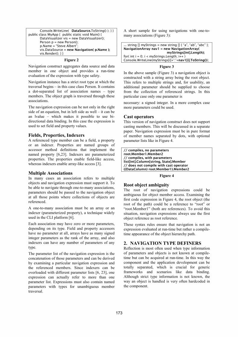
Console.WriteLine( DataSource.ToString() ); } } public class MyApp { public static void Main() {
DataVisualizer vis = new DataVisualizer(); Person p = new Person(); p.Name = “Steve Albert”; vis.DataSource = new Navigation( p.Name ); vis.Render(); } }
Figure 2 Navigation construct aggregates data source and data member in one object and provides a run-time evaluation of the expression with type safety. Navigation instance has a strict root type at which the traversal begins – in this case class Person. It contains a dot-separated list of association names – type members. The object graph is traversed through these associations. The navigation expression can be not only in the right side of an equation, but in left side as well – it can be an lvalue – which makes it possible to use bi-directional data binding. In this case the expression is used to set field and property values.
Fields, Properties, Indexers A referenced type member can be a field, a property or an indexer. Properties are named groups of accessor method definitions that implement the named property [6,23]. Indexers are parameterized properties. The properties enable field-like access, whereas indexers enable array-like access [3].
Multiple Associations In many cases an association refers to multiple objects and navigation expression must support it. To be able to navigate through one-to-many associations, parameters should be passed to the navigation object at all those points where collections of objects are referenced. A one-to-many association must be an array or an indexer (parameterized property), a technique widely used in the CLI platform [6]. Each association may have zero or more parameters, depending on its type. Field and property accessors have no parameter at all, arrays have as many signed integer parameters as the rank of the array, and also indexers can have any number of parameters of any type. The parameter list of the navigation expression is the concatenation of those parameters and can be derived by examining a particular navigation expression and the referenced members. Since indexers can be overloaded with different parameter lists [6, 23], one expression can actually refer to more than one parameter list. Expressions must also contain named parameters with types for unambiguous member traversal.
A short sample for using navigations with one-to-many associations (Figure 3):
... string [] myStrings = new string [] { “a”, “ab”, “abc” }; NavigationArray nav1 = new NavigationArray(
myStrings[int].Length); for( int i = 0; i < myStrings.Length; i++ ) Console.WriteLine(myStrings[i]+’:’+nav1[i].ToString());
Figure 3 In the above sample (Figure 3) a navigation object is constructed with a string array being the root object. This refers to multiple strings and, for usability, an additional parameter should be supplied to choose from the collection of referenced strings. In this particular case only one parameter is necessary: a signed integer. In a more complex case more parameters could be used.
Cast operators This version of navigation construct does not support casting members. This will be discussed in a separate paper. Navigation expression must be in pure format of member names separated by dots, with optional parameter lists like in Figure 4.
// compiles, no parameters root.Member1.Member2 // compiles, with parameters list[int].Column[string, State].Member // does not compile with cast operator ((DataColumn) root.Member1).Member2
Figure 4
Root object ambiguity The root of navigation expressions could be ambiguous for object member access. Examining the first code expression in Figure 4, the root object (the root of the path) could be a reference to “root” or “root.Member1” (both are references). To avoid this situation, navigation expressions always use the first object reference as root reference. These syntax rules ensure that navigation is not an expression evaluated at run-time but rather a compile-time appearance of the object hierarchy path.
2. NAVIGATION TYPE DEFINERS Reflection is most often used when type information of parameters and objects is not known at compile-time but can be acquired at run-time. In this way the component and the application development can be totally separated, which is crucial for generic frameworks and scenarios like data binding. Although strict type information is not known, the way an object is handled is very often hardcoded in the component.
173

For example a component that displays matrix data uses data source as a two-dimensional array. A component which displays a table uses data source as a list and each column refers to a specific data member. In these scenarios the data source must satisfy the demands of the component, preferably checked at compile-time. To support this requirement, navigation expressions are strictly typed. The component that uses the navigation as a data source determines the parameters and also the return type of the expression. The type declarations for Navigation and NavigationArray with respect to the above samples (Figure 2 and Figure 3) are as follows:
navigation object Navigation;navigation int NavigationArray( int i );
Figure 5 Navigation declaration and instantiation with navigation expression are depicted in Figure 6. However, a more formal definition can be found in Appendix A: Formal C# language definition:
navigation type TypeName( formal-parameter-list ); TypeName var = new TypeName(
navigation-expression );
Figure 6 These types are generated automatically by the compiler from the navigation declaration. Variables of these types can only hold a reference to navigation instances which have the same number of parameters and the type of each parameter is the same or inherited from the appropriate type in the navigation declaration. The return type expression must also match the type in the declaration with equality or inheritance. In this way the component can safely use data source which conforms to its requirements and forms a matrix, a list, etc. A client application is verified at compile-time to check whether it supports the appropriate data source with type safe member references. All this results in a type-safe data binding.
Inheritance and Access Modifiers The type where the navigation object is created must have access to the referenced members. Private fields, properties, indexes can be used only when the class itself declares a navigation to its own members. Protected members can be used in derived classes, internal members [6] in the same compilation unit (assembly) accordingly. Public members can be used anywhere.
A navigation type declaration can be public, internal, protected or private just like a class declaration. These modifiers define the visibility of the navigation type just like class visibility does. Once a navigation type is instantiated, it can be used by any class. If a method of class A receives a navigation object as a parameter, the method can use it to access the referenced member independently of whether class A has access to the member referenced by the expression or not. The compiler checks, for all but the last of properties and fields and indexers in the association list, whether they are readable and all are accessible by the declaring class which creates the navigation object. No write-only members are allowed through the association path except the last one. An expression is read-only if the last member is a read-only member for the instantiating class, write-only if it is write-only, and normal otherwise.
Comparison to Delegates In CLI delegates are used as “object-oriented type-safe function pointers” [6, 3]. They share common ideas with navigation expressions. In both cases a special language element is used for type definer which allows type-safety by identifying methods to invoke or members to be accessed later. The syntax is quite similar, too [23, 3] (Figure 7):
void PrintInt( int i ) { Console.WriteLine( i ); } delegate void MethodDelegate( int a ); MethodDelegate del =
new MethodDelegate( this.PrintInt ); del( 42 ); navigation int myNavigation( int ); string [] myStrings = new string [] { “a”, “ab”, “abc” }; myNavigation nav1 = new myNavigation(
myStrings[int].Length ); Console.WriteLine( nav1[2] );
Figure 7 The difference between the language constructs is that the delegates are applicable to methods but not to fields or properties (even though properties are implemented as methods in CIL). Moreover, delegates do not support navigation in the object hierarchy; they only have a reference to a class instance and a handle referencing a method of that type. Navigations hold an entire reference path to navigate through the object hierarchy and reach the addressed field or property through multiple associations. Data binding on .NET platform uses properties and not methods for member access. Hence in that case delegates are not applicable and cannot be used for data binding.
174

3. COMPILER IMPLEMENTATION A "compiler only" solution can be provided if only one language is taken into consideration. After checking syntax (see Section 5) and type consistency the compiler generates extra code in place of declaration, instantiation and usage (see Appendix B). Each navigation declaration is a type creator syntax element (similar to class, interface, delegate and array sign (‘[ ]’) [6, 23, 3]). The abstract type (class A) is constructed by the compiler and is unique for each navigation declaration. For each object hierarchy path, a unique class (class B : A) is generated by the compiler which finally derives from type created for navigation declaration. Class A contains two abstract methods for reading and writing members (GetValue and SetValue methods). Parameter lists are generated according to the navigation declaration. Derived Class B provides implementation for these abstract methods, using strict type information. Using reflection, dynamic navigation creation can also be supported but it is not recommended, since it ensures no type safety at all. In this scenario a program can create navigation expression instances at runtime, based on strings. To measure performance impact we have modified the Mono C# compiler. The compiler-generated type safe navigation expressions are 10 to 50 times faster than a reference solution with reflection. The advantage of this “compiler only” approach is that the runtime environment remains unchanged. Only language compilers should be extended to provide the new functionality. Similarly to delegates, a navigation declaration is also a type declaration and this type could be a basis for language interoperability which is essential on the CLI platform.
4. CONCLUSION In this paper we have introduced a new C# language construct that provides more type-safe solution with compile-time errors rather than run-time errors. The new language construct called navigation supports access to class members through multiple parameterized one-to-many associations and similarly to delegates, a navigation declaration is also a type declaration. This solution is not only more type-safe but can also provide a huge gain of performance in many application scenarios.
5. APPENDIX A : FORMAL C# LANGUAGE DEFINITION The following list is the extension to C# language grammar [23, Appendix A].
A.1.7 Keywords, Keyword: navigation
A.2.2 Types Reference type: navigation-type Navigation-type: type-name
A.2.4 Expressions Primary-no-array-creation-expression:
navigation-creation-expression
Expression: navigation-creation-expression: new navigation-type ( navigation-expression ) Navigation-expression:
expression navigation-expression . identifier
navigation-expression . identifier [ type-list ]Type-list: type | type-list , type
A.2.5. Statements Type-declaration: navigation-declaration
A.2.13. Navigations, navigation-declaration: attributesopt navigation-modifiersopt navigation type identifier( fixed-parametersot )
navigation-modifiers:navigation-modifier
navigation-modifiers navigation-modifier navigation-modifier:new | public | protected |
internal | private
6. APPENDIX B : ILLUSTRATION OF THE COMPILER GENERATED CODE Navigation declaration:
public navigation string gridNavigation( int row, int column );
Generated code:
public abstract class gridNavigation :BaseNavigation {
public abstract void SetValue( int row, int column, string value );
public abstract string GetValue( int row, int column );
}
175

Navigation instantiation: string [][] birthData = new string [][] { new string [] {
“Blaise Pascal”, “1623-1662”, “Clermont” }, new string [] { “Sir Isaac Newton”, “1642-1727”, “Woolsthorpe” },…
}; … gridNavigation nav1 = new gridNavigation(
birthData [int][int] );
Generated code: … public sealed class gridNavigation_nav1 :
gridNavigation { String [][] rootObj; public myNavigation_1( string [][] root ) {
rootObj = root; } public override string GetValue(
int row, int column) { return rootObj[row][column]; }
public override void SetValue( int row, int column, string value) {
rootObj[row][column] = value; } }…gridNavigation nav1 =
new gridNavigation_nav1( birthData );
Navigation usage: public class DataGrid {
public gridNavigation DataSource; public int RowNumber, ColumnNumber; public void Render() {
for( int r = 0; r < RowNumber; r++ ) { for( int c = 0; c < ColumnNumber; c++ ) {
Console.Write( DataSource[r, c] ); if( c < ColumnNumber – 1 )
Console.Write( “, “ ); } Console.WriteLine(); } } }
Generated code: … for( int c = 0; c < ColumnNumber; c++ ) {
Console.Write(DataSource.GetValue( r, c ) ); if( c < ColumnNumber – 1 )Console.Write( “, “ );
} …
7. REFERENCES [1] A. Kennedy and D. Syme.: Design and implementation of generics for the .NET Common Language Runtime. ACM SIGPLAN, PLDI, pages 1–12, Snowbird, Utah, June 2001. [2] A. Homer, D. Sussman, M. Fussell: First Look at ADO.NET and System.Xml v.2.0 (Addison Wesley, 2003) [3] A. Hejlsberg, S. Wiltamuth, P. Golde, The C# Programming Language (Addison Wesley, 2003) [4] B. Meyer, Eiffel: the language (Prentice Hall, New York, NY, first edition, 1992) [5] B. Joy, G. Steele, J. Gosling, G. Bracha, The Java Language Specification, Second Edition ( Addison-Wesley, 2000) [6] ECMA-335 Common Language Infrastructure (CLI), ECMA, December 2001. http://www.ecma.ch/ [7] ECMA TC39-TG2/2004/14, C# Language Specification, Working Draft 2.7, Jun, 2004
[8] Gartner Inc. (Michael J. Blechar): The Impact of Web Services Architecture on Application Development, 26 August 2002 [9] Gartner Inc.: J2EE and .NET Will Vie for E-Business Development Efforts, 28 April 2003 [10] Gartner Inc. (Joseph Feiman): The Gartner Programming Language Survey, 1 October 2001 [11] G. Bracha, M. Odersky, D. Stoutamire: Making the future safe for the past: Adding genericity to the programming language. OOPSLA, ACM, Oct. 1998. [12] International Standard: Programming Languages - C++. ISO/IEC. 2003. Number 14882:2003 (E) in ASC X3, ANSI, New York, NY, USA. [13] JSR 12: JavaTM Data Objects (JDO) Specification. http://jcp.org/en/jsr/detail?id=12, 2003 [14] JSR-14, Add Generic Types To The Java Programming Language. Available on line at http://jcp.org/en/jsr/detail?id=014, 2004 [15] K. B. Bruce. Typing in object-oriented languages: Achieving expressibility and safety. Technical report, Williams College, 1996. [16] M. Lucia Barron-Estrada, R. Stansifer: A Comparison of Generics in Java and C#, 41st ACM Southeast Regional Conference, March 2003 [17] M, Hericko, M, B. Juric, I. Rozman, S. Beloglavec, A. Zivkovic, Object serialization analysis and comparison in Java and .NET., SIGPLAN Notices 38(8): 44-54 (2003) [18] O. Agesen, S. Frølund, and J. C. Mitchell.: Adding parameterized types to Java. In Object-Oriented Programming: Systems, Languages, Applications, pages 215-230. ACM, 1997. [19] R. Bruce Findler, M. Latendresse, M. Felleisen, Behavioral contracts and behavioral subtyping, ACM SIGSOFT Software Engineering Notes, Volume 26 , Issue 5, September 2001 [20] S. Chiba, A Metaobject Protocol for C++, ACM Conference on Object-Oriented Programming Systems, Languages, and Applications, 1995 [21] S. Roiser, Reflection in C++, CERN, February 2004 (Available on-line at http://doc.cern.ch//archive/electronic/cern/others/LHB/internal/lhcb-2003-116.pdf) [22] R. Finkel: Advanced Programming Language Design (Addison Wesley, 1995) [23] Standard ECMA-334 C# Language Specification, ECMA, December 2001. Available on-line at http://www.ecma.ch/
176

Adaptive Object Modelling using the
.NET Framework
Theo Crous, Theo Danzfuss Computer Science Department
University of Pretoria Pretoria 0002 South Africa
{tcrous, tdanzfuss}@cs.up.ac.za
Andreas Liebenberg, Alwyn Moolman E-Logics (Pty) Ltd
Unit L12 Enterprise Building Innovation Hub Pretoria 0002 South Africa
{andreas.liebenberg, alwyn.moolman}@elogics.co.za
ABSTRACT In an ever-changing business environment, business models and rules have migrated from compiled source code to external metadata. This paradigm better known as adaptive object modelling (AOM) empowers domain experts to take control over application implementations, and allows them to change an application’s business model as the business evolves. The problem with the adaptive object modelling approach is that it only caters for an evolving business model and ignores the effects of expanding functional requirements. This paper presents the Expandable Software Infrastructure (ESI), an amalgamation of adaptive object modelling and component-based software development. Unlike other adaptive object modelling implementations where metadata have only been used to describe the data and the executing domain, the ESI takes metadata further and utilizes it to describe the data, domain, behaviour and components - providing us with a truly expandable AOM. We highlight how the relatively complex task of adaptive object modelling can be executed simply and elegantly using the Microsoft .NET Framework and further describe how core .NET technologies such as ADO.NET, .NET Compact Framework, reflection and remoting sculpted the architecture of the ESI. We conclude with the notion of moving towards a standardized, intelligent architecture that executes on multiple platforms.
Keywords Adaptive Object-Model, Adaptive Systems, Dynamic Object-Model, Reflection, Reflective Systems Meta-Modelling, Meta-Architectures, Metadata, Domain Specific Language, Generative Programming.
1. INTRODUCTION Business needs have developed beyond the capacity of statically structured systems that are unable or unwilling to adapt to changing business requirements.
These requirements for flexible systems can briefly be described as:
- Runtime configurability
- Adaptability
- Extendibility
- Intuitive configuration
Existing approaches to flexible systems have all excelled in at least one of the above mentioned objectives, but none have successfully adhered to all 4 requirements.
We present the Expandable Software Infrastructure (ESI) developed by E-Logics (Pty) Ltd: an adaptive object modelling system that makes use of various techniques found in configurable and/or flexible systems and component-based software development. The ESI’s goal is to realize all 4 requirements through the use of metadata and can be briefly described as a metadata-driven component-based framework.
Permission to make digital or hard copies of all or part of this work for personal or classroom use is granted without fee provided that copies are not made or distributed for profit or commercial advantage and that copies bear this notice and the full citation on the first page. To copy otherwise, or republish, to post on servers or to redistribute to lists, requires prior specific permission and/or a fee. .NET Technologies’2005 conference proceedings, ISBN 80-86943-01-1 Copyright UNION Agency – Science Press, Plzen, Czech Republic
177

The main contribution of our work is to make an effective use of the .NET Framework to successfully design and develop a flexible system, the Expandable Software Infrastructure (ESI) that conforms to all four above mentioned requirements. We also demonstrate how the ESI was influenced by the .NET framework and focus on the role of .NET Technologies such as ADO.NET, .NET Compact Framework, reflection and remoting in the ESI.
This paper is structured as follows: Section 2 describes the ESI and gives an overview of the high level architecture and metadata structure and a layered view of the ESI. Section 3 presents an in-depth look at the physical architecture of the ESI and how .NET sculpted the architecture. Section 4 scrutinizes existing approaches to flexible systems while Section 5 details some future work draws conclusions.
2. THE ESI
The Expandable Software Infrastructure (ESI) is both a software component infrastructure and an adaptive object model interpreter. Development of the ESI was driven by various business requirements. These requirements are to:
- Develop changeable systems
- Reduce development time and cost
- Intuitively develop systems
- Develop flexible systems
- Develop vendor independent systems
- Reuse common software components
Essentially the ESI is an interpretive layer wrapped around traditional relational database systems, which allows domain experts to build, configure and deploy systems without the need to rewrite or recompile code. The ESI allows domain experts to concentrate on domain modelling, system configuration and maintenance while software developers concentrate on technical issues.
The ESI owes its flexibility to the extensive use of metadata. Metadata is used to describe the domain model, software components, component variability and behaviour. This implies that most changes in the business environment can be catered for by making changes to metadata. Should the need for new functionalities arise, a component that sufficiently fulfils the requirements must be purchased or developed and then described in the metadata. The component’s variability refers to those parameters of
the component that will be variable for different domains. It is then the responsibility of a domain expert to populate the variability for the executing domain.
The ESI provides a range of tools to assist users with the tedious task of populating metadata. The most notable of these tools is the ESI management console. The management console provides an UML [13] modelling tool that users can use to describe the domain. The management console also enables users to extend the ESI by describing new components and their variability.
ESI Metadata The ESI metadata is a self-describing object model that can be divided into three layers, as illustrated in figure 1.
The Core is used to describe those entities that are critical to the execution of any ESI implementation. Extended metadata are those data that describe the pluggable components while domain metadata is specific for a given implementation.
The core ESI object model is loosely based on design patterns found in classic AOM implementations [2] namely:
- TypeObject Pattern
- Entity and EntityType Pattern
- Property Pattern
- Strategy Pattern
The main differences between the core ESI object model and these classic AOM patterns are that the ESI architecture is split into a functional and a physical level and the ESI metadata is self-describing. The advantages gained by this architecture are:
- The physical relational database model can differ from the functional object model.
Figure 1. ESI metadata
178

- Technical details stored in the physical layer can be hidden from domain experts, providing a more intuitive model.
- One functional model can easily be migrated to a different physical implementation.
- The core of the ESI can be extended.
Figure 2 presents a graphical representation of the core ESI object model.
Changing core metadata results in a new ESI assembly to be built. This assembly is generated by interpreting the stored metadata and generating a new dynamic link library (dll) using the reflection and emit libraries found in .NET. The newly built assembly now forms the base of all ESI systems.
3. ESI AND THE .NET FRAMEWORK Before the acceptance of component-based frameworks such as J2EE and .NET, implementing a system such as the ESI was an extremely daunting and often impractical task. The following advantages of the .NET Framework [10, 14] made it the perfect candidate for the ESI:
- Low learning curve
- Ease of application deployment and maintenance
- Comprehensive class library - Managed Code - Framework support
The decision to choose the .NET framework was not only based on technical merit, but also on non-
technical factors such as available resources and user expectations.
The architecture of the ESI was sculpted by the .NET Framework. ADO.NET, remoting, reflection and the .NET Compact Framework were the defining technologies in the structure of the ESI.
ADO.NET and especially datasets enabled the implementation of a data abstraction layer that is vendor-independent and can also treat text-based data stores such as XML and CSV files similar to relational databases. It also provided the ability to create an efficient client-side data cache that reduces network traffic and improves overall system performance.
The .NET remoting infrastructure enables the ESI to execute in a distributed environment over either TCP or HTTP. This permits the ESI to provide rich client interfaces that can retrieve data over the internet and even through firewalls.
.NET Reflection is used to extend the ESI at run time. New types and operations can be added to the ESI by defining them in the metadata. The ESI then uses reflection to load the type at runtime. The ESI also makes use of the .NET emit library to allow for the core ESI to be extended and recompiled by simply altering the metadata.
The .NET Compact Framework allows the ESI to execute on mobile devices such as PDA’s. This extends the range of applications that can be executed using the ESI.
The ESI allows multiple deployment scenarios of which the most common is essentially a distributed client-server architecture as highlighted in figure 3.
Figure 2. Core ESI Architecture
Figure 3. ESI deployment scenario
179

As seen in Figure 4 the ESI can be broken into nine distinct components. Each of these components leverages the .NET framework to reach its goal.
1. The Data Abstraction Layer: The data abstraction layer is responsible for performing basic Create, Read, Update and Delete commands (CRUD) on all the supported data sources.
2. Meta Interpretation Layer: The metadata interpretation layer uses the data abstraction layer to load and save the metadata. Metadata are converted into runtime classes through the reflection API, and all classes built on top of the interpretation layer will use these classes as if they were compiled at design time.
3. Remote Server Interface: The remote server interface is responsible for managing remote client connections and executing all server side operations such as data retrieval. The Remote Server Interface uses the .NET remoting infrastructure to provide basic remoting functions such as object serialization.
4. Client Data Cache: The client data cache reduces network traffic and improves response time, by caching results in a disconnected data set.
5. Client Data Service: The client data service is responsible for executing all client-side
operations and managing access to the local data cache.
6. Client View: The client view is a thin wrapper around a .NET dataset that presents users (typically GUI components) with a meta interpreted view on the data. Without a client view user interface components only see a dataset, with the client view user interface components see a collection of metadata objects.
7. Remote Data Service: The remote data service is used by data services to communicate remotely with each other.
8. UI Controls: User interface controls provide users a view on the data and a mechanism to interact with ESI clients. Currently the ESI contains two sets of UI controls; Windows Forms controls and Mobile Controls. Windows Forms controls are extensions to .NET provided controls and allow for ESI-specific functionalities. Mobile controls are UI controls that execute on the .NET Compact Framework and often implement a subset of the functionalities provided by the Windows Forms version of the controls.
9. Synchronization: Synchronization is used to keep secondary and mobile servers in sync with the primary ESI server.
4. COMPARISON WITH EXISTING APROACHES We categorize existing flexible system approaches into the following categories:
- Configurable Systems - Adaptive Object Modelling - Component-based Software Development
Configurable Systems A configurable system extends the traditional notion of a system by introducing a fixed set of parameters external to the system. These parameters can be modified to alter some runtime attributes or properties of a system. The Gandiva software development system [11] can be seen as an example of a configurable system.
Configurable systems are limited by a fixed set of parameters which are defined at compile time. Therefore the dimensions of configurability are fixed and the scope for adapting is limited.
Figure 4. ESI layered architecture
180

The ESI relates to configurable systems in that it allows users to configure the system using external attributes. ESI differs from configurable systems by allowing the definition of variability in metadata – enabling the extension of configurable parameters.
Adaptive Object Modelling An adaptive object model (AOM) [14] is an object model where the domain representation is interpreted at runtime and can be altered or changed with immediate effect [1]. The adaptive model defines mechanisms to describe entities, attributes and relationships, as well as mechanisms to interpret the domain model and execute business rules. Browsersoft’s eQ! Foundation [15] is a good example of an industry stable AOM implementation written in Java.
The biggest shortfall of the AOM approach is its internal structures are difficult to extend and maintain. This results in the situation where business requirements can easily be adapted although the functional requirements of the system cannot change easily. We can say AOM systems are adaptive although not adaptable [4, 5].
In addition to using metadata to describe the domain, the ESI also utilizes metadata to define software components, their variability and behavior. This provides the ESI with information that can be used to expand the system on a functional level.
Component-based Software Development In component-based software development, software products are built on top of component infrastructures [9]. The component infrastructure provides a mechanism for business components to be plugged in and configured to produce a final software product or system. A software system can be extended by plugging in new components or replacing old components. The best known example of a component infrastructure is probably Enterprise Java Beans [16].
Although component infrastructures can be easily extended to provide new functionality, they often requires writing “glue” code to make the new functionalities available.
The ESI provides a pluggable component infrastructure that enables it to expand on a functional level. Instead of having to write code to plug the new components into the framework, the ESI requires the component to be described in metadata.
Table 1 summarizes which objectives are successfully met by each flexible system approach.
The ESI is an ideal solution when implementing systems in a constantly changing environment, which requires flexible, configurable, intuitive and adaptable systems.
These systems may span any number of domains, including: asset management, data warehousing, geographical information, decision support and supply chain optimization systems.
5. CONCLUSION AND FUTURE WORK Developing an adaptive object modelling system is not an easy task. Choosing the correct technology is critical to simplifying this undertaking. The .NET Framework enabled a small team of software developers to conquer this mammoth task within reasonable time. This success can be broadly credited to .NET’s low learning curve, the comprehensive class library, ease of deployment, managed code and excellent support. The ESI overcomes the shortcomings of classic adaptive object modelling systems by introducing aspects from component-based software development. Although the infrastructure is currently being used by a number of industry applications there are a few shortcomings:
- It is limited to the Microsoft Windows and Windows CE platform.
- No web or thin client interface exists. - Does not conform to standards, therefore it
is difficult to extend the ESI with a component that was not developed for the ESI.
Runtime configurable
Adaptive Extendible Intuitive
Configurable Systems
Adaptable Object Modelling
Component-based Software Development
Expandable Software Infrastructure
Table 1. ESI comparison
181
- The ESI currently lacks version control and change management.
Apart from the shortcomings mentioned above we would like to see the ESI move towards an intelligent or adaptable architecture [9]. The simplest example of resource adaptation is that of network bandwidth. The system must detect low bandwidths and modify caching settings and request processing accordingly. Another goal for the ESI would be to make it platform independent. With recent developments in the ROTOR and MONO projects, we would like to see the ESI execute on one of these frameworks, thus enabling cross-platform execution.
6. ACKNOWLEDGMENTS
The authors would like to thanks E-Logics (Pty) Ltd for allowing them to work on the ESI and for funding the project. Also a word of thanks to Prof. Judith Bishop, Department Computer Science, University of Pretoria, for her guidance and support.
7. REFERENCES [1] J.W. Yoder, B. Foote, Metadata and Active
Object-Models. 1998. [2] J.W. Yoder et al. Architecture and Design of
Adaptive Object-Models. ACM SIG-PLAN Notices 36, No.12, pp.50-60, 2001.
[3] R. Reza et al. Language support for Adaptive
Object-Models using Metaclasses. ESUG Conference, 2004.
[4] A. Dantas et al. Using Aspects to Make Adaptive
Object-Models Adaptive. ECOOP ‘04 Workshop on Reflection, AOP, and Meta-Data for software evolution (RAM-SE), pp.9-20, 2004.
[5] K. Lieberherr, Workshop on Adaptable and
Adaptive Software. Addendum to the Proceedings of the 10th annual OOPSLA, ACM Press, pp.149-154, 1995.
[6] J. van Gurp, J. Bosch, M. Svahnberg. On the
Notion of Variability in Software Product Lines. In Proceedings of the working IEEE/IFIP
conference on Software Architecture (WICSA'01), 2001.
[7] L. Baum, M. Becker. Generic Components to
Foster Reuse. System Software Research Group, University of Kaiserslautern, 2001.
[8] C.W. Young, M. Young, Deploying solutions
with .NET Enterprise Servers. ISBN: 0-471-23594-6. Wiley Publishers, 2003.
[9] R. Allen , R. Douence, D. Garlan, Specifying and
Analyzing Dynamic Software Architectures. Lecture Notes in Computer Science, Vol. 1382, pp.21, 1998.
[10]G. Heineman, W. Councill, Component-Based
software engineering. Putting the pieces together. ISBN: 0-201-70485-4. Addison Wesley, 2001.
[11] M. Stuart, C. Wheather, C. Mark, The Design
and Implementation of a Framework for Configurable Software. Proceedings of the 3rd International Conference on Configurable Distributed Systems (ICCDS ‘96)
8. WEB REFERENCES [12] S. Pratschner. Simplifying Deployment and
Solving DLL Hell with the .NET Framework. http://msdn.microsoft.com, November 2001.
[13] Unified Modelling Language.
http://www.uml.org, January 2005. [14] MetaData and Adaptive Object-Model Pages.
http://www.adaptiveobjectmodel.com, January 2005.
[15] The eQ! Foundation. http://www.browsersoft.com/, December 2004 [16] SunMicrosystems. J2EE 1.3 specification.
URL:http://java.sun.com/j2ee/download.html, July 2001.
182

A Highly Available Replicated File System for Resource-Constrained Windows CE .Net Devices1
João Barreto2 and Paulo Ferreira
INESC-ID/IST Rua Alves Redol N.º 9
1000-029 Lisboa, Portugal
{joao.barreto, paulo.ferreira}@inesc-id.pt
ABSTRACT The emergence of more powerful and resourceful mobile devices, as well as new wireless communication technologies, is turning the concept of mobile ad-hoc networking into a viable and promising solution for ubiquitous information sharing. However, the inherent characteristics of mobile ad-hoc networks bring up important challenges for any embedded application developed with the goal of information sharing in the novel usage scenarios enabled by mobile ad-hoc environments. This paper proposes transparent system-level support for Windows CE.Net applications by means of a replicated file system, Haddock-FS. Haddock-FS is based on an adaptable optimistic consistency protocol that provides a highly available access to a weakly consistent view of file, while delivering a strongly consistent view to more demanding applications. In order to effectively cope with the network bandwidth and device memory constraints of these environments, Haddock-FS employs a cross-file, cross-version content similarity exploitation mechanism.
Keywords Distributed file systems, optimistic replication, mobile ad-hoc networks, Windows CE.Net.
1. INTRODUCTION The evolution of the computational power and
memory capacity of mobile devices, combined with their increasing portability, is creating computers that are more and more suited to support the concept of ubiquitous computation [Wei91]. As a result, users are progressively using mobile devices, such as handheld or palmtop PCs, not only to perform many of the tasks that, in the past, required a desktop PC, but also to support innovative ways of working that are now possible. At the same time, novel wireless communication technologies have provided these portable devices with the ability to easily interact with other devices through wireless network links. Inevitably, effective ubiquitous information access is a highly desirable goal.
Many real life situations already suggest that users could benefit substantially if allowed to
cooperatively interact using their mobile devices and without the requirement of a pre-existing infrastructure. A face-to-face work meeting is an example of such a scenario. The meeting participants usually co-exist within a limited space, possibly for a short period of time and may not have access to any pre-existing fixed infrastructure. 12
If each participant holds a mobile device with wireless capabilities, a mobile ad-hoc network [Cor99] may serve the purposes of the meeting. This way, a report held at one participant’s handheld device might be shared with the remaining meeting participants’ devices, while its contents are analyzed and discussed. Furthermore, each participant might even update the shared report’s contents, thus contributing to the ongoing collaborative activity.
One interesting solution for ubiquitous information sharing is the use of a distributed file system. This approach allows already existing applications to access shared files in a transparent manner, using the same programming interface as for the local file system. However, the nature of the scenarios we are addressing entails significant challenges for an effective DFS solution to be devised. The following lines introduce the main 1 This work was partially funded by Microsoft Research. 2 Funded by FCT Grant SFRH/BD/13859.
Permission to make digital or hard copies of all or part of this work for personal or classroom use is granted without fee provided that copies are not made or distributed for profit or commercial advantage and that copies bear this notice and the full citation on the first page. To copy otherwise, or republish, to post on servers or to redistribute to lists, requires prior specific permission and/or a fee. .NET Technologies’2005 conference proceedings, ISBN 80-86943-01-1 Copyright UNION Agency – Science Press, Plzen, Czech Republic
183

requirements imposed by such challenges that determined the architectural options of our contribution.
High availability. The high topological dynamism of mobile ad-hoc networks entails frequent network partitions. Moreover, the possible absence of a fixed infrastructure means that most situations will require the services within the network to be offered by mobile devices themselves. Such devices are typically severely energy-constrained. As a result, the services they offer are susceptible to frequent suspension periods in order to save battery life of the server's device. From the client's viewpoint, such occurrences are similar to server failures.
These aspects emphasize the need for high availability replication services, so as to minimize the effects of the expectable network partitions and device suspension periods. Pessimistic replication approaches, employed by conventional distributed file systems, such as NFS [Now98] or AFS [Mor86], are too restrictive to fulfill such a requirement.
Adaptability to different correctness criteria. Optimistic replication strategies offer high availability as a trade-off for consistency. While certain applications are able to benefit from such increased availability, some application semantics demand stronger consistency guarantees. In order to be adaptable to a wider set of applications, replicated systems should offer multiple consistency levels: from a relaxed consistency, highly-available to a sequentially consistent mode of replica access.
Adaptation to resource-constrained devices. Whichever strategy is taken, the memory and bandwidth limitations of mobile devices and wireless links, respectively, must be taken into account. For optimistic strategies, the update log is the main memory overhead, while network usage is typically dominated by replica synchronization.
This paper describes Haddock-FS, a transparent replicated file system for Windows CE.Net collaborative applications, including .Net Compact Framework applications. Haddock-FS is based on a highly available optimistic consistency protocol. In order to cope with the resource constraints of mobile devices, Haddock-FS employs content similarity exploitation mechanisms. The paper focuses on the main implementation issues regarding Haddock-FS and the Windows CE.Net development environment. Furthermore, a thorough experimental evaluation using actual embedded devices is presented.
The rest of the paper is organized as follows: Section 2 introduces the main architectural aspects. Section 3 addresses application programming interface aspects, while Section 4 describes the implementation of Haddock-FS. Section 5 presents
experimental results. Finally, Section 6 describes related work and Section 7 draws some conclusions.
2. ARCHITECTURE This section briefly introduces the architecture
of Haddock-FS, as originally proposed in [Bar04a].
File System Consistency Haddock-FS is a transparent, peer-to-peer
replicated file system designed to support a broad set of usage scenarios that are made possible by mobile networks. It relies on a hybrid consistency architecture, based on epidemic propagation of replica updates, that accommodates for applications with differing consistency demands: a tentative view, supporting any-time, anywhere read and write access to shared files, at the cost of weak consistency guarantees; and stable view, offering sequentially consistent [Lam79] access to shared files as a trade-off for reduced write availability.
Each Haddock-FS mobile peer constitutes a replica manager that is able to receive file system requests and perform them upon its local replicas. The underlying replication mechanisms are transparent to applications, which may access Haddock-FS's services by using the same API as the one exported by the local file system. Provided the accessed files are locally replicated at a given Haddock-FS peer, the file system services will be available, independently of the current network connectivity.
Update propagation is achieved by pair-wise reconciliation sessions between mutually accessible replica managers, where replica updates are epidemically propagated. Complementarily, Haddock-FS uses a primary commit scheme [Ter95], in which a single replica of each file, the primary replica, is responsible for selecting new stable updates and propagating such decision back to the remaining replicas. Each file is initially assigned a unique primary replica, at which it was originally created. After creation, primary replica rights may be transferred to other replicas, by exchanging a token that identifies the current primary replica.
For each file replica, a replica manager maintains: a stable value, which holds a version of the file's stable contents and an update log, which records the data specifications of most recent update requests that have been accepted by the file replica.
Content storage and propagation The inherent memory and bandwidth constraints
of mobile devices and wireless links are severe limitations to the effectiveness of a distributed file system for ad-hoc environments. For this reason, Haddock-FS tries to reduce the size of update logs stored at each device, as well as of update data to be transferred during replica reconciliation.
184

This is achieved by exploiting the cross-file and cross-version similarities that exist within the replicated data held by Haddock-FS's mobile peers. Such approach is based on that of the Low-Bandwidth File System (LBFS) [Mut01].
The basic idea of the content storage and transference scheme consists of applying the SHA-1 [NIS95] hash function to portions of each replica's contents; each portion is called a chunk. The obtained hash values can be used to univocally identify their corresponding chunk contents. From this assumption, if two chunks produce the same output upon application of the SHA-1 hash function, then they are considered to have the same contents.
A content-based approach is employed to divide replica contents into a set of variable-size non-overlapping chunks, in order to minimize the effect of insert-and-shift operations in the global chunk structure of a replica [Mut01].
Haddock-FS extends the use of LBFS's strategy to both local storage and network transference of replicated file data. Our solution considers the existence, on each file system peer, of a common chunk repository which stores all data chunks, indexed by their hash value, that comprise the contents of the files that are locally replicated at that peer. The data structures associated with the content of locally replicated files simply store references to chunks in the chunk repository. This applies both to the update log and the stable value of each replicated file. Hence, the contents of an update or replica value consist of a singly linked list of references to data chunks, stored in the chunk repository (see Figure 1). So, if different files or versions of the same file contain data chunks with similar contents, then they will share references to the same entry in the chunk repository, thus reducing memory usage.
Read accesses to a file's contents can be served by a single indirect memory access to the chunks referenced by the chunk references stored in the file's data structures. Serving a write request upon a local replica is, in turn, a more expensive operation. In order to optimize situations where already stored contents are modified in a partial region, an incremental chunk update algorithm [Bar04b] is used. Such algorithm ensures that only a minimum
set of affected chunks, from the original contents chunk list, is actually re-evaluated.
Update propagation between peers also makes use of the chunk repositories of each peer. When a chunk has to be sent across the network to another peer, only its hash value is firstly sent. The receiving peer then looks up its chunk repository to see if that chunk is already stored locally. If so, it avoids the transference of that chunk's content and simply stores a reference to the already existing chunk. Otherwise, the chunk contents are sent and a new chunk is added to the repository.
3. Application Programming Interface Haddock-FS exports the same application
programming interface (API) as the standard file system API of Windows CE.Net. Examples of such interfaces are the standard CreateFile, CloseFile, ReadFile and WriteFile. Therefore, any existing Windows CE.Net application that is originally built to access the local file system may transparently use Haddock-FS’s replicated file services.
In particular, if one considers application programming using the .NET Compact Framework, programmers may continue to use conventional class libraries such as System.IO.FileStream or System.IO.File to access and manipulate file system objects of Haddock-FS. Since the implementation of these classes relies on the standard file system API, file system objects located within Haddock-FS’s name space may be transparently accessed.
Nevertheless, some specific aspects of Haddock-FS’s behavior are not controllable by the conventional file system API; namely, the aspects related to the replication protocol. This implies that some extended control must be provided beyond the conventional file system API. Such control should allow users to perform replication operations while running replication-blind applications that solely rely on the conventional file system API to manipulate Haddock-FS’s objects. Examples of such operations are switching from a tentative to a stable view of an opened file, and vice-versa, and to transfer primary replica rights to another accessible replica. Replication control should also be granted to programmers that wish to develop replication-aware applications for use with Haddock-FS.
Replication control is provided by means of reserved control codes passed to the standard DeviceIoControl interface, also exported by Haddock-FS. The actual calls to DeviceIoControl are performed by a replication control class library, which replaces the interaction with DeviceIoControl with a more programmer-friendly interface. Currently, a replication control class library is available for use by .Net Compact Framework applications, which extends the standard
Figure 1. Example of replica content storage.
185

System.IO.FileStream class. Illustrative methods of the class are shown in Table 1. bool switchToTentativeView(); bool switchToStableView(); bool grantPrimaryRights(RepId destRep); Table 1. Example of replica control class methods.
4. Implementation Haddock-FS is an Installable File System Driver
[Mur98] for the MS Windows CE.Net embedded operating system. The current version supports the replica consistency protocol, as well as cross-file and cross-version similarity storage and network usage optimizations. All relevant file system functions are implemented. Interaction between peers is achieved using a remote procedure call library that was developed along with Haddock-FS.
Installable File System Driver Haddock-FS’s API is exported by an installable
file system driver (IFSD), in the form of a dynamic link library. Such programming interface is comprised of file system functions, which form the client side of each Haddock-FS’s peer. Using the LoadFSD function of the FSD Manager service of Windows CE.Net, the file system can be mounted at run time.
The server side of each peer resides in a thread of the Device Manager process that is created when the file system is mounted. The server thread is continually waiting for remote procedure call requests from other peers across the network. Such requests are served upon access to the file system data structures stored in the address space of Device Manager process. On the other hand, the file system functions that are exported by the dynamic link library constitute the client side of each peer. Most of such functions access the shared data structures of the server thread.
4.1.1 Data structures Haddock-FS maintains a collection of data
structures in the address space of the Device Manager process, where the IFSD is loaded. Most of the exported file system functions access and modify such data structures when called. The most relevant data structures are as follows. Chunk repository, as described in Section 2. Root directory, which contains a hierarchical
representation of the file system objects (directories and files) that are currently known by the local peer, including their relevant file system attributes; their creation, modification and access times and read-only, hidden or archive flags. In the case of locally replicated file objects, replication information is also included.
Open file table, holds entries for the files that are currently opened by some process. Each entry contains information about the current file pointer position, as well as the share mode and access type, specified when the file was opened.
4.1.2 Exported File System Interfaces The file system interfaces that are exported and
implemented by Haddock-FS’s IFSD may be grouped into the following categories [Mur98]:
1. Device event interfaces, which handle the initialization and termination procedures of the file system driver. These events correspond, respectively, to the MountDisk and UnmountDisk functions. Such functions are not available to applications through the file system API. Instead, they are only called by FSD Manager in order to mount or unmount the IFSD. The MountDisk function is responsible for: registering a volume where Haddock-FS’s shared file system structure will be accessible to applications; initializing the local file system data structures and RPC services; and creating a server thread, which will handle all remote requests from other Haddock-FS peers. Inversely, the UnmountDisk function handles deregistration of the file system volume and termination of the server thread.
2. Path-based interfaces, which access or modify file system objects that are identified by their alphanumeric path names when the interface is called by applications, such as CreateDirectoryW. Every path-based function first decomposes and analyzes each path name argument so as to locate the corresponding element in the root directory structure. The requested operation is then performed.
3. Handle-based interfaces, which access or modify files that are identified by a previously obtained file handle, such as ReadFile or WriteFile. A file handle is obtained by a call to the CreateFileW function, in which a path name is passed as an argument to identify the desired file. Additionally, other relevant arguments specify the intended share mode and type of access. Similarly to any path-based function, the supplied path name is used to obtain a reference to the corresponding file element in the root directory structure. If found, the open file table is examined to verify that no sharing conflicts will occur with the current entries in that table. Finally, if such requirement is fulfilled, a new entry is then inserted into an empty slot of the open file table and its position within the table is returned. Such integer value is a file handle that must be used by succeeding calls to handle-based file system functions to the same opened file.
4. Find interfaces, which allow applications to iterate through the list of file system objects whose path name matches a given search string. Namely, FindFirstFileW, FindNextFileW and FindClose.
186
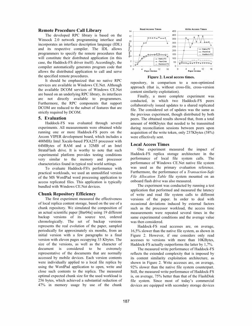
Remote Procedure Call Library The developed RPC library is based on the
Winsock 2.0 network programming interface and incorporates an interface description language (IDL) and its respective compiler. The IDL allows programmers to specify the remote procedures that will constitute their distributed application (in this case, the Haddock-FS driver itself). Accordingly, the compiler automatically generates program code that allows the distributed application to call and serve the specified remote procedures.
It should be emphasized that no native RPC services are available in Windows CE.Net. Although the available DCOM services of Windows CE.Net are based on an underlying RPC library, its interfaces are not directly available to programmers. Furthermore, the RPC components that support DCOM are reduced to the subset of features that are strictly required by DCOM. 5. Evaluation
Haddock-FS was evaluated through several experiments. All measurements were obtained while running one or more Haddock-FS peers on the Arcom VIPER development board, which includes a 400MHz Intel Xscale-based PXA255 processor with 64MBytes of RAM and a 32MB of an Intel StrataFlash drive. It is worthy to note that such experimental platform provides testing conditions very similar to the memory and processor characteristics found in typical real world settings.
To evaluate Haddock-FS's performance with practical workloads, we used an unmodified version of the MS WordPad word processing application to access replicated files. This application is typically bundled with Windows CE.Net devices.
Chunk Repository Efficiency The first experiment measured the effectiveness
of local replica content storage, based on the use of a chunk repository. We simulated the composition of an actual scientific paper [Bar04a] using 19 different backup versions of its source text, ordered chronologically. The set of backup versions represents the real evolution of the paper, sampled periodically for approximately six months, from an initial version with a few paragraphs to a final version with eleven pages occupying 33 Kbytes. The size of the versions, as well as the character of document is considered to be extremely representative of the documents that are normally accessed by mobile devices. Each version contents were individually applied to a local file replica by using the WordPad application to open, write and close such contents to the replica. The measured optimal expected chunk size for the used workload is 256 bytes, which achieved a substantial reduction of 47% in memory usage by use of the chunk
repository, in comparison to a non-optimized approach (that is, without cross-file, cross-version content similarity exploitation).
Finally, a more complete experiment was conducted, in which two Haddock-FS peers collaboratively issued updates to a shared replicated file. The considered set of updates was the same as the previous experiment, though distributed by both peers. The obtained results showed that, from a total amount of 460Kbytes that needed to be transmitted during reconciliation sessions between peers upon acquisition of the write token, only 237Kbytes (58%) were effectively sent.
Local Access Times One experiment measured the impact of
Haddock-FS replica storage architecture in the performance of local file system calls. The performance of Windows CE.Net native file system was used as the primary evaluation reference. Furthermore, the performance of a Transaction-Safe File Allocation Table file system mounted on an onboard flash drive was also measured.
The experiment was conducted by running a test application that performed and measured the latency of write and read file system calls to different versions of the paper. In order to deal with occasional deviations induced by external factors such as the processor workload, the access time measurements were repeated several times in the same experimental conditions and the average value was then considered.
Haddock-FS read accesses are, on average, 16,5% slower than the native file system, as shown in Figure 2. However, if one considers only read accesses to versions with more than 10KBytes, Haddock-FS actually outperforms the latter by 1,7%.
The measured write performance of Haddock-FS reflects the extended complexity that is imposed by its content similarity exploitation architecture, as shown in Figure 2. Write accesses are, on average, 92% slower than the native file system counterpart. Still, the measured write performance of Haddock-FS is, on average, 75% better than that of the FlashDisk file system. Since most of today’s commercial devices are equipped with secondary storage devices
Figure 2. Local access times.
187

with similar access performance, this evidence suggests that typical mobile users will tolerate Haddock-FS’s write access performance. 6. Related Work
The issue of optimistic data replication for loosely coupled environments has been addressed by a number of projects, most of which do not assume that replicas will be held by resource-constrained devices. Bayou [Ter95] is an optimistic database replication system that relies on application-specific conflict detection and resolution procedures to attain adaptable consistency guarantees. The non-transparent character of Bayou's approach prohibits the use of already existing applications, in contrast to Haddock-FS's solution.
The Roam [Rat99] optimistically replicated file system does not require replica managers to store an update log, which eliminates the significant memory overhead that is typically imposed by such a data structure. Nevertheless, Roam's consistency protocol does not regard any notion of a stable replica value. This limitation restricts Roam's applicability to applications with sufficiently relaxed correctness criteria that tolerate dealing only with tentative data.
AdHocFS [Bou03] exploits the high connectivity of ad-hoc groups of replica managers by enforcing a pessimistic strategy amongst the group members. Nevertheless, AdHocFS's architecture is still based on the existence of fixed server infrastructures, where the stable values of files are held. Therefore, should that infrastructure be unavailable, users and applications are restricted to accessing merely tentative data.
Finally, content similarity has already been exploited for storage purposes by the Pastiche backup system [Cox02], so as to minimize storage overhead on backed-up contents. However, Pastiche’s file system does not employ incremental writes to chunked contents; instead, each write operation causes the resulting contents to be re-processed by the chunk division process. Though acceptable for back-up operations, such solution may not be adequate for partial content modifications. 7. Conclusions
Haddock-FS is a replicated file system designed to meet the requirements imposed by mobile ad-hoc scenarios, in order to provide a viable support for
collaborative activities. Namely, high availability, adaptability to different correctness criteria and adaptation to resource-constrained devices.
Haddock-FS has been successfully implemented in Windows CE.Net and tested in Arcom VIPER XScale-based development boards. Experimental results show that Haddock-FS accomplishes significant network and memory usage reductions when compared to traditional solutions, while attaining acceptable access times.
8. References [Bar04a] Barreto, J. and Ferreira, P.. A Replicated File
System for Resource Constrained Mobile Devices. Proceedings of IADIS Applied Computing, 2004.
[Bar04b] Barreto, J. Haddock-FS: A Distributed File System for Mobile Ad-hoc Networks. M.Sc Thesis, Instituto Superior Técnico, 2004.
[Bou03] Boulkenafed, M. and Issarny, V. Adhocfs: Sharing files in wlans. Proceedings of the 2nd IEEE International Symposium on Network Computing and Applications, Cambridge, MA, USA, 2003.
[Cor99] Corson, S. and Macker, J. Mobile ad hoc networking (MANET): Routing protocol performance issues and evaluation considerations. Internet RFC 2501, IETF, 1999.
[Cox02] Cox, L., and Noble, B. Pastiche: Making backup cheap and easy. Proceedings of 5th OSDI, 2002.
[Lam79] Lamport, L.. How to make a multiprocessor computer that correctly executes multiprocess programs. IEEE Transactions on Computers, 1979.
[Mor86] Morris, J. et al. Andrew: a distributed personal computing environment. Communications of the ACM, 29(3):184–201, 1986.
[Mur98] Murray, J. Inside Microsoft Windows CE. Microsoft Press, 1998.
[Mut01] Muthitacharoen, A., Chen, B. and Mazieres, D. A low-bandwidth network file system. SOSP, 2001.
[NIS95] National Institute of Standards and Technology. FIPS PUB 180-1: Secure Hash Standard. National Institute for Standards and Technology, USA, 1995.
[Now89] Nowicki, B. Nfs: Network file system protocol specification. Internet RFC 1094, IETF, 1989.
[Rat99] Ratner, D., Reiher, P. and Popek, G. Roam: A scalable replication system for mobile computing. Mobility in Databases and Distributed Systems,1999.
[Ter95] Terry, D. et al. Managing update conflicts in bayou, a weakly connected replicated storage system. Proceedings of the 5th ACM SOSP, 1995.
[Wei91] Weiser, M.. The computer for the twenty-first century. Scientific American, 265:94–1, 1991.
188
The Zonnon Project: A .NET Language and Compiler Experiment
Jürg Gutknecht Swiss Fed Inst of Technology
(ETH) Zürich, Switzerland
Vladimir Romanov Moscow State University
Computer Science Department Moscow, Russia
Eugene Zueff Swiss Fed Inst of Technology
(ETH) Zürich, Switzerland
ABSTRACT
Zonnon is a new programming language that combines the style and the virtues of the Pascal family with a number of novel programming concepts and constructs. It covers a wide range of programming models from algorithms and data structures to interoperating active objects in a distributed system. In contrast to popular object-oriented languages, Zonnon propagates a symmetric compositional inheritance model. In this paper, we first give a brief overview of the language and then focus on the implementation of the compiler and builder on top of .NET, with a particular emphasis on the use of the MS Common Compiler Infrastructure (CCI). The Zonnon compiler is an interesting showcase for the .NET interoperability platform because it implements a non-trivial but still “natural” mapping from the language’s intrinsic object model to the underlying CLR.
Keywords Oberon, Zonnon, Compiler, Common Compiler Infrastructure (CCI), Integration.
1. INTRODUCTION: THE BRIEF HISTORY OF THE PROJECT This is a technical paper presenting and describing the current state of the Zonnon project. Zonnon is an evolution of the Pascal, Modula, Oberon language line [Wir88]. Major language concepts and some considerations concerning the system architecture were presented in a number of papers during the last two years [Gut02, Gut03].
The project emerged from our participation in Projects 7 and 7+, a collaboration initiative launched by Microsoft Research in 1999 with the goal of implementing an exemplary set of non-standard programming languages for the .NET interoperability platform. Our part was Oberon for .NET, an interoperable descendant of Pascal and Modula-2.
The motivation for continuing the research was twofold: a) to explore the potential of .NET and in particular of the new compiler integration technology
CCI and b) to experiment with evolutionary language concepts. The notion of active object was taken from the Active Oberon language [Gut01]. In addition, two new concurrency mechanisms have been added: an accompanying communication mechanism based on syntax-oriented protocols , borrowed from the Active C# project [Gun04], and an experimental “asynchronous” statement execution construct.
The new language was called Zonnon. It uses a compositional inheritance model. Typically, an object implements a specified set of definitions, each one accompanied by a default implementation that is aggregated into the object’s state space. The syntax of Zonnon is presented in the [Zon05] document.
2. CURRENT STATE OF THE PROJECT The core language is defined and stable but there are still ongoing experiments in the area of concurrency. The current compiler is a well-tested beta version. A specifically developed comprehensive Zonnon test suite containing more than 1500 Zonnon test cases and covering all language features is used for systematic testing of the compiler.
There are three user environments for the Zonnon compiler: command-line, Zonnon Builder and Visual Studio .NET. We note that, to the best of our knowledge, the Zonnon compiler is the first compiler
Permission to make digital or hard copies of all or part of this work for personal or classroom use is granted without fee provided that copies are not made or distributed for profit or commercial advantage and that copies bear this notice and the full citation on the first page. To copy otherwise, or republish, to post on servers or to redistribute to lists, requires prior specific permission and/or a fee. .NET Technologies’2005 conference proceedings, ISBN 80-86943-01-1 Copyright UNION Agency – Science Press, Plzen, Czech Republic
189

developed outside of Microsoft that is fully integrated into Visual Studio. It is currently used in an experimental programming course for junior students in Nizhny Novgorod University, Russia [Ger05].
3. BRIEF INTRODUCTION TO ZONNON Being a member of Pascal family of languages and thanks to a high degree of compatibility, Zonnon is immediately familiar to Modula/Oberon programmers. Most Oberon programs from the domain of algorithms and data structures are successfully compiled by the Zonnon compiler after just a few minor modifications.
However, from the perspective of “programming-in-the-large”, Zonnon is much more elaborate compared to its predecessors. There are four different kinds of program units in Zonnon: objects, modules, definitions and implementations. The first two are program units to be instantiated at runtime, the third is a compile time unit of abstraction and the fourth is a unit of composition. Here is a brief characterization:
Object is a self-contained run-time program entity. It can be instantiated dynamically under program control in arbitrary multiplicity. Compared to Oberon, the notion of object is conceptually upgraded in Zonnon by the option of adding one or more encapsulated activities that control the intrinsic behavior of the object.
Module can be considered as a singleton object whose creation is controlled by the system. In addition, a module may act as a container of logically connected abstract data types and structural units of the runtime environment. In combination with the import relation, the module construct is a powerful system structuring tool that is missing in most modern object-oriented languages.
Definition is an abstract view on an object from a certain perspective or, in other words, an abstract presentation of one or more of its facets.
Implementation typically provides a possibly partial default implementation of the corresponding definition. It is a unit of reuse and composition that is aggregated into the state space of an object or module either at compile time or at runtime.
Zonnon also provides a novel object-oriented concurrency model that follows the metaphor of autonomous active objects interoperating with each other. The model incorporates encapsulated threads of activity serving two purposes: expressing intrinsic behavior and carrying out formal dialogs. Active C# provides a proof of concept for this concurrency model.
4. ZONNON MAPPINGS TO CLR As mentioned before, the Zonnon object model differs from the virtual object model proposed by the .NET CLR. However, most Zonnon concepts can be mapped rather easily to corresponding CLR notions, with the help of a few minor tricks. The general approach taken was trying to make direct use of CLR high-level constructs rather than to optimize the Zonnon code image. In the following, we will consider some important mapping examples.
Zonnon definitions are represented as public interfaces, and their state variables are mapped to virtual properties. For example, the following sample definition
(* Common interface for the random numbers generator *) definition Random; var { get } Next : integer; (* read-only *) procedure Flush; (* reset *) end Random.
is mapped to the class:
public interface Random { System.Int32 Next { get; } void Flush(); }
Implementations are mapped to sealed classes with the same visibility as corresponding definitions. For example, a possible implementation of the random generator will look like as follows:
implementation Random; var { private } z : integer; procedure { public, get } Next : integer; const a = 16807; m = 2147483647; q = m div a; r = m mod a; var g : integer; begin g := a*(z mod q) – r*(z div q); if g>0 then z := g else z := g+m end; return z*(1.0/m) end Next; procedure Flush; begin z := 3.1459 end Flush; begin Flush; end Random.
The compiler will generate code for this implementation that corresponds to the C# class:
public sealed class Random_implem : Random { private System.Int32 z; System.Int32 Random.Next { get { …; } } void Random.Flush ( ) { z = 3.1459; } public Random_Implem() { Flush(); } }
If no implementation is specified for a definition then the compiler generates a default implementation with
190

trivial properties. The example below illustrates this for the Random definition:
(*automatically generated definition companion*) public sealed class Random_default : Random { System.Int32 Next_default; System.Int32 Random.Next { get { return Next_default; } } }
Zonnon object types actually behave like CLR classes and therefore are mapped to sealed classes with the same scope of visibility as the object type. In case a body is specified in an object type, it is mapped into an instance constructor as shown here:
object { public } R; public sealed class R { var x : real; private System.Double x; begin public R ( ) { … x := 777.999; … x = 777.999; … } end R. }
The relationship “object implements definition” is a fundamental constituent in the Zonnon object model. It represents an obligation for an object type to provide the functionality promised by the definition. However, notice that a corresponding implementation (if it exists) is automatically imported by the compiler, and the object type needs to merely implement the missing parts and, if desired, to customize the default implementation. For example:
object R1 implements Random; (*implicitly imports Random implementation*) (* Procedure Next is reused from default implementation *) (* Procedure Flush is customized *) procedure Flush implements Random.Flush; begin z := 2.7189; end Flush; end R.
The “object implements definition” relationship is represented as a usual interface implemented by the class. To support the automatic reuse of the default implementation, its “class” image is aggregated into the class image of the object itself. Thus, the above object type shown will be represented as follows:
class R1: Random { private Random_implem implem; public System.Int32 Random.Next() { return implem.Next(); } public void Flush() { z = 2.7189; } }
Finally, Zonnon modules are mapped to sealed classes (either public or internal, depending on the module’s modifier) with static members, public static constructor (for the method body) and private instance constructor (to prevent uncontrolled creation of module instances) with empty body.
module Test; import Random; (* both definition and implementation are imported *) var x : object { Random }; (* x’s actual type is any type implementing Random *) object R2 implements Random; (*alternative random number implementation*) end R2; begin x := new R1; … x := new R2; … end Test.
5. THE ZONNON COMPILER
Compiler overview The Zonnon compiler is written in C#. It accepts Zonnon program units and produces conventional .NET assemblies containing MSIL code and metadata. The Common Compiler Infrastructure (CCI) provided by Microsoft is used as a code generation utility and integration platform.
Technically the compiler is a single dll file that is directly integrated into Visual Studio and the Zonnon Builder environment, respectively. A small executable wrapper is added to make the command-line version of the compiler.
The Common Compiler Infrastructure Conceptually, CCI provides three kinds of support for developing compilers for .NET (see Fig 5.1): high-level infrastructure (in particular, structures for building attributed program trees and methods for performing semantic checks on trees), low-level support (generating IL code and metadata), and programming service for integration.
From the programming perspective, the CCI is a set of C# classes that provide comprehensive support for implementing compilers and other language tools for .NET. In reality, the support is not fully comprehensive as, for example, lexical and syntactical analyses are left to the user. However, the CCI supports well the integration into Visual Studio (VS). With the support of CCI a full integration of a compiler with all VS components such as editor, debugger, project manager, online help system etc. becomes feasible.
The CCI framework should be considered as a part of the .NET framework, with the namespace Compiler containing the CCI resources included in the System namespace. It consists of three major parts:
191
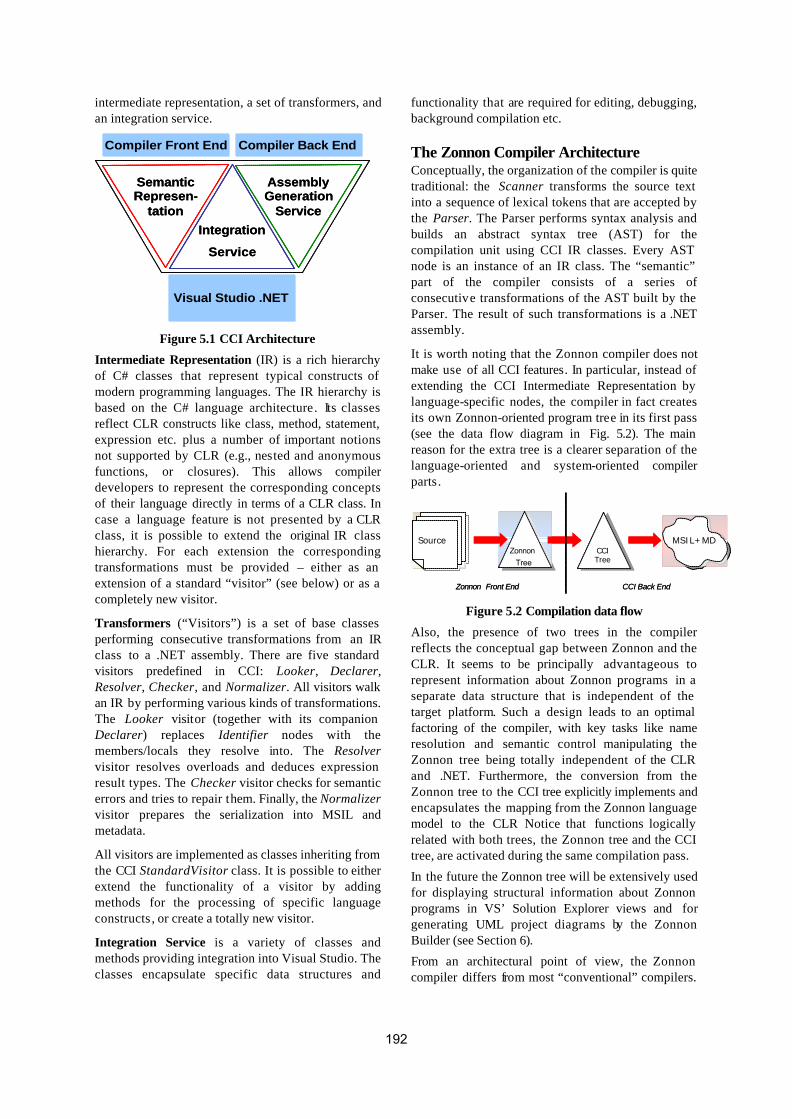
intermediate representation, a set of transformers, and an integration service.
Integration
Service
SemanticRepresen-
tation
Assembly Generation
Service
Visual Studio .NET
Compiler Front End Compiler Back End
Integration
Service
SemanticRepresen-
tation
Assembly Generation
Service
Visual Studio .NET
Compiler Front End Compiler Back End
Figure 5.1 CCI Architecture
Intermediate Representation (IR) is a rich hierarchy of C# classes that represent typical constructs of modern programming languages. The IR hierarchy is based on the C# language architecture. Its classes reflect CLR constructs like class, method, statement, expression etc. plus a number of important notions not supported by CLR (e.g., nested and anonymous functions, or closures). This allows compiler developers to represent the corresponding concepts of their language directly in terms of a CLR class. In case a language feature is not presented by a CLR class, it is possible to extend the original IR class hierarchy. For each extension the corresponding transformations must be provided – either as an extension of a standard “visitor” (see below) or as a completely new visitor.
Transformers (“Visitors”) is a set of base classes performing consecutive transformations from an IR class to a .NET assembly. There are five standard visitors predefined in CCI: Looker, Declarer, Resolver, Checker, and Normalizer. All visitors walk an IR by performing various kinds of transformations. The Looker visitor (together with its companion Declarer) replaces Identifier nodes with the members/locals they resolve into. The Resolver visitor resolves overloads and deduces expression result types. The Checker visitor checks for semantic errors and tries to repair them. Finally, the Normalizer visitor prepares the serialization into MSIL and metadata.
All visitors are implemented as classes inheriting from the CCI StandardVisitor class. It is possible to either extend the functionality of a visitor by adding methods for the processing of specific language constructs , or create a totally new visitor.
Integration Service is a variety of classes and methods providing integration into Visual Studio. The classes encapsulate specific data structures and
functionality that are required for editing, debugging, background compilation etc.
The Zonnon Compiler Architecture Conceptually, the organization of the compiler is quite traditional: the Scanner transforms the source text into a sequence of lexical tokens that are accepted by the Parser. The Parser performs syntax analysis and builds an abstract syntax tree (AST) for the compilation unit using CCI IR classes. Every AST node is an instance of an IR class. The “semantic” part of the compiler consists of a series of consecutive transformations of the AST built by the Parser. The result of such transformations is a .NET assembly.
It is worth noting that the Zonnon compiler does not make use of all CCI features. In particular, instead of extending the CCI Intermediate Representation by language-specific nodes, the compiler in fact creates its own Zonnon-oriented program tree in its first pass (see the data flow diagram in Fig. 5.2). The main reason for the extra tree is a clearer separation of the language-oriented and system-oriented compiler parts.
Figure 5.2 Compilation data flow
Also, the presence of two trees in the compiler reflects the conceptual gap between Zonnon and the CLR. It seems to be principally advantageous to represent information about Zonnon programs in a separate data structure that is independent of the target platform. Such a design leads to an optimal factoring of the compiler, with key tasks like name resolution and semantic control manipulating the Zonnon tree being totally independent of the CLR and .NET. Furthermore, the conversion from the Zonnon tree to the CCI tree explicitly implements and encapsulates the mapping from the Zonnon language model to the CLR Notice that functions logically related with both trees, the Zonnon tree and the CCI tree, are activated during the same compilation pass.
In the future the Zonnon tree will be extensively used for displaying structural information about Zonnon programs in VS’ Solution Explorer views and for generating UML project diagrams by the Zonnon Builder (see Section 6).
From an architectural point of view, the Zonnon compiler differs from most “conventional” compilers.
Source Source CCI Tree
MSIL+MD Zonnon
Tree
Zonnon Front End CCI Back End
Source Source CCI Tree
MSIL+MD Zonnon
Tree
Zonnon Front End CCI Back End
192

In contrast to a “black box” approach whose goal is to hide algorithms and data structures, our Zonnon compiler presents itself as an open collection of resources. In particular, data structures such as “token sequence” and “AST tree” are exhibited to the outside world (via a special interface) for reuse by various programs . The same is true for algorithmic compiler components. For example, it is possible to invoke the Scanner to extract tokens from some specific part of the source code and then have the Parser build a sub-tree for just this part of the source.
Note that an analogous architecture is used by the CCI framework to support the deepest integration of any participating compiler with the Visual Studio environment. For example, the CCI contains Scanner and Parser prototype classes that served as base classes for the Zonnon parser and scanner components respectively.
6. THE ZONNON BUILDER The Zonnon Builder is a conventional development environment comparable with many other IDEs. Our first goal in equipping the compiler with its own IDE was to provide an environment that looks familiar to Pascal programmers who are used to products like Delphi. On the other hand the Zonnon Builder can be considered as a simpler and light-weight alternative to full-featured environments like Visual Studio. The Zonnon Builder supports the full spectrum of a typical program development cycle, including source code editing, compiling, execution, testing and debugging. The Zonnon Builder supports structured projects consisting of several source files. Multi-file projects are compiled into a single assembly. It is possible to edit project files in different syntax-oriented editor windows simultaneously.
The second goal of the Zonnon Builder project was to offer a simple and comprehensible development environment for novices, specifically supporting the case of a simplified program development cycle in that a single program file is being developed, compiled, debugged and run. Such an option is very useful and convenient in an educational context .
The Zonnon Builder uses a special window to display compiler diagnostics. These are actually hyperlinks that can be clicked directly to visualize the part of the source code containing the (highlighted) error. In case of a program crash, the contents of the program stack are displayed in a separate window. The sections in the stack window are again hyperlinks (see Fig.6.1) and clicking at a section again causes the Builder to display and highlight the corresponding fragment of the source code.
Figure 6.1 Zonnon program debugging
The Zonnon Builder also provides a simple version control mechanism. It is possible to save, restore and compare an arbitrary number of revisions for each project file (see Fig.6.2).
Figure 6.2 File versioning
Version control for the entire project is also supported. Each project version holds the state of all project files at a given time, together with an optional textual comment.
The Zonnon Builder Implementation The Zonnon Builder as a whole is implemented in the form of a conventional .NET application. Its graphical user interface implementation reuses the standard .NET libraries System.Drawing and System.Windows. Forms. Some key components of the Builder such as the Zonnon-oriented program editor need to directly call the system API (user32.dll) because some functionality is missing in the .NET class libraries.
The design of the Zonnon Builder is intentionally kept largely independent of the specific programming language. Remaining dependences are encapsulated in two interfaces (see Fig.6.3).
193

Figure 6.3 Zonnon Builder implementation
The ICompiler interface hides the implementation of the compiler. The Zonnon compiler wrapper implements the interface. The ILanguageLexems interface hides all language specific parts, for example the set of tokens. Therefore, it is easy to integrate any other programming language into the environment.
7. FUTURE WORK Zonnon and Visual Studio We aim at a closer integration with the Solution Explorer, including adequate interpretation of CLR notions (such as “type”, “class”, “method” etc.) in accordance with the semantics of the Zonnon language (“module”, “definition”, “procedure” etc.). We also strive for a closer integration of the object content presentation and the “intellisense” feature.
Zonnon Builder The next Zonnon Builder version will include a code model for compiled Zonnon programs. Programs will be presented as a hierarchical tree whose nodes represent Zonnon compilation units and their contents , respectively. Another improvement will be automatic generation of UML diagrams for the static structure of Zonnon programs. The UML diagrams will visually present the different relationships between compilation units. Both presentation forms (code model and UML diagrams) will be integrated with the program text presentation. The integration with the standard CLR debugger is also planned.
8. LESSONS LEARNED The experience in using the Zonnon language shows that it is quite convenient and can be used both for educational purposes (as the first programming language) and as an implementation tool. Some practical programs with non-trivial algorithms and graphical user interface were implemented in this language. The Chess Notebook program from the Zonnon web site is among the examples.
We are quite satisfied with the CCI framework. It is a well-designed, practical, powerful and flexible tool for
building VS integrated compilers. It supports both the integration of existing compilers into the Visual Studio and the development of integrated compilers from scratch. CCI also can be considered as a more powerful and faster alternative to the System.Reflection library. The troubles with CCI were the lack of documentation and the unclear status of this framework.
9. CONCLUSIONS Zonnon is the new programming language with a number of novel programming concepts and constructs. The language covers a wide range of programming models. This paper describes the current state of the Zonnon project: the language, the compiler and its development environment. The Zonnon compiler is also integrated into Microsoft’s Visual Studio .NET environment.
The command-line Zonnon compiler, the Zonnon Builder, the Zonnon Language Report together with documentation and a large number of Zonnon program samples and tests are available on www.zonnon.ethz.ch.
10. ACKNOWLEDGMENTS Our thanks go to Herman Venter, Brian Kirk, David Lightfoot, Alan Freed and to the first Zonnon users and programmers.
11. REFERENCES [Ger05] Prof V.Gergel, personal communication. [Gun04] R. Güntensperger and J. Gutknecht, Active
C#, Proceedings of the 2nd International Workshop on .NET Technologies, Plzen 2004.
[Gut01] Gutknecht, J., Active Oberon for .NET: An Exercise in Object Model Mapping, BABEL’01, Satellite to PLI’01, Florence, IT, 2001.
[Gut02] J.Gutknect, E.Zueff, Zonnon Language Experiment, or How to Implement a Non-Conventional Object Model for .NET. OOPSLA’02, November 4-8, 2002, Seattle, Washington, USA.
[Gut03] J.Gutknecht, E.Zueff, Zonnon for .NET – A Language and Compiler Experiment. Joint Modular Languages Conference, JMLC2003, Klagenfurt, Austria, August 2003.
[Wir88] Wirth, N., The Programming Language Oberon. Software – Practice and Experience, 18:7, 671-690, Jul. 1988.
[Zon05] J.Gutknecht, E.Zueff, Zonnon Language Report, www.zonnon.ethz.ch.
194
A Virtual Machine Framework for Domain Specific Languages
David Fick
[email protected] Derrick G. Kourie
Espresso Research Group University of Pretoria
South Africa, Pretoria, Gauteng
Bruce W. Watson [email protected]
ABSTRACT
A generic approach to constructing a virtual machine for a DSL in C# is studied. It proposes a generic, object-oriented framework, in which to build the virtual machine, using an abstract instruction class and an abstract environment class. They can be extended to provide a concrete layer whose interface constitutes the set of instructions of a DSL. The framework allows for the generation of a variety of virtual machines each supporting a particular DSL. Comparative performance results in relation to other DSL implementations are also provided.
Keywords virtual machine, domain-specific language, instruction set, environment, abstract class, generic framework.
1. INTRODUCTION Domain specific languages (DSLs) have been discussed and used in many contexts. (See, for example, [Arn95] and [Deu98].) In this paper the design and implementation of a VM Framework for DSLs is investigated, using .NET. Two other approaches for constructing a DSL are also briefly examined. For all three approaches, time of execution is examined and timed points are declared. The Shlaer-Mellor (SM) software construction method has been adopted. A fundamental difference between SM and other methods is the identification of separate subject matters, called domains. An SM domain is a separate real, hypothetical, or abstract world inhabited by a distinct set of classes that behave according to rules and policies characteristic of the domain [Shl92a]. The VM Framework is layered on top of an existing domain. As a programming language construct, a domain is simply represented as a namespace. The namespace forms a home for related classes and these classes facilitate the semantics of the DSL.
The VM Framework outlined in this study is an extension to the typical VM, in that it defines a VM with an empty instruction set whose environments and instructions can later be extended.
2. FRAMEWORK DESIGN The VM Framework provides the basic functionality of a typical VM, including an Intermediate Representation (IR) program loader, a program counter, internal temporary values, and conditions on which to build branching instructions. A proxy object is provided through which to start up and configure an instance of a VM. No modification to the VM Framework itself is required and its component classes can consequently be compiled and saved as a library. The VM Framework consists of five main classes each discussed in the following subsections, and is shown in figure 1.
The EVM Class The EVM class (Extendable Virtual Machine) is the proxy class. Once instantiated, the object represents an instance of a configurable VM, with an empty instruction set and no environment. A specific configuration can then be applied to the VM instance. When an IR program is executed, the VM will invoke the correct Inst instance created at load time, defined in the configuration file. The EVM class also encapsulates the internal temporary values in the temps hash table. Each internal temporary value has a unique ID, and instructions with ID operands can gain read and write access to them. The temporary
Permission to make digital or hard copies of all or part of this work for personal or classroom use is granted without fee provided that copies are not made or distributed for profit or commercial advantage and that copies bear this notice and the full citation on the first page. To copy otherwise, or republish, to post on servers or to redistribute to lists, requires prior specific permission and/or a fee. .NET Technologies’2005 conference proceedings, ISBN 80-86943-01-1 Copyright UNION Agency – Science Press, Plzen, Czech Republic
195
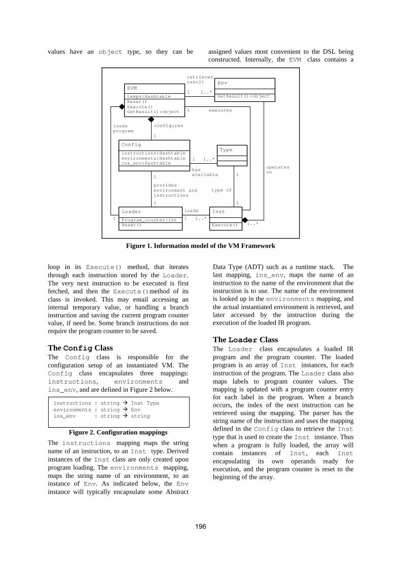
values have an object type, so they can be assigned values most convenient to the DSL being constructed. Internally, the EVM class contains a
EVM
temps:Hashtable Reset() Execute() GetResult():object
retrieves result
executes
operates on has
available
loads
configures
provides environment and instructions
loads program
1 1..*
1..*
1
1
1
1
1
1
1 1..*
type of
1
1 1..*
Env
GetResult():object
Config
instructions:Hashtableenvironments:Hashtableins_env:Hashtable
Loader
Program_counter:int Reset()
Inst
Execute()
Type
Figure 1. Information model of the VM Framework
loop in its Execute() method, that iterates through each instruction stored by the Loader. The very next instruction to be executed is first fetched, and then the Execute()method of its class is invoked. This may entail accessing an internal temporary value, or handling a branch instruction and saving the current program counter value, if need be. Some branch instructions do not require the program counter to be saved.
The Config Class The Config class is responsible for the configuration setup of an instantiated VM. The Config class encapsulates three mappings: instructions, environments and ins_env, and are defined in Figure 2 below.
instructions : string Inst Type environments : string Env ins_env : string string
Figure 2. Configuration mappings The instructions mapping maps the string name of an instruction, to an Inst type. Derived instances of the Inst class are only created upon program loading. The environments mapping, maps the string name of an environment, to an instance of Env. As indicated below, the Env instance will typically encapsulate some Abstract
Data Type (ADT) such as a runtime stack. The last mapping, ins_env, maps the name of an instruction to the name of the environment that the instruction is to use. The name of the environment is looked up in the environments mapping, and the actual instantiated environment is retrieved, and later accessed by the instruction during the execution of the loaded IR program.
The Loader Class The Loader class encapsulates a loaded IR program and the program counter. The loaded program is an array of Inst instances, for each instruction of the program. The Loader class also maps labels to program counter values. The mapping is updated with a program counter entry for each label in the program. When a branch occurs, the index of the next instruction can be retrieved using the mapping. The parser has the string name of the instruction and uses the mapping defined in the Config class to retrieve the Inst type that is used to create the Inst instance. Thus when a program is fully loaded, the array will contain instances of Inst, each Inst encapsulating its own operands ready for execution, and the program counter is reset to the beginning of the array.
196

The Inst Abstract Class The abstract Inst class encapsulates a reference to a Env. This will be the environment updated by the instruction during the execution of the loaded IR program. Note that it is only a reference and other instructions will have a reference to the same Env instance. The Inst class does not define how the updates are performed, and instead provides an abstract Execute() method, that further extensions to the instruction are obligated to override. While there are still instructions to be executed by the loaded program, the Execute() method is called for each instruction. When the program counter has run through each instruction instance, the program has completed execution and the result of the execution can be retrieved.
The Env Abstract Class The abstract Env class encapsulates some ADT, or even a number of ADT’s that form the central data storage mechanism for the language. The abstract Env class does not dictate the type of ADT that is encapsulated, and thus does not define any member ADT. It merely provides an abstract GetResult() method that extensions of Env are obligated to override.
3. ENVIRONMENTS The purpose of the abstract Env class is to have an ADT that is updated during runtime, and that is appropriate, or convenient for processing the semantics of the language. For example, in a simple real-valued expression language, a runtime stack can be used as an environment, where operands are first loaded onto the stack and then an arithmetic operation is performed on the most recently pushed values. In a ray-tracer [Wat00a] scene description language, the main data structure may be a runtime stack, for any arithmetic calculations, and a bitmap image data type that is incrementally updated as the image information is processed. Thus it is possible to extend the environment built for an expression language, into one that is suitable for a ray-tracer language. Classes that extend the abstract Env class, are obligated to override the method GetResult(). The method GetResult() returns an instance of an object. When an instance of a VM has completed execution, the user can call GetResult() to retrieve the result of the execution. In the example of an expression language, this would typically be a double value, while for a ray-tracer language this result would be an instance of a bitmap image type. Since framework users will be aware of the data type they are using for the result, a simple type cast to narrow
the returned instance to the user’s own result type is sufficient. An example of EnvExp, a concrete extension to Env for an expression language, is provided in Figure 3. It encapsulated a real-valued stack, and returns the last entry on the stack. If all operations on the stack are consistent, there should be only one remaining value on the stack, which is the result of evaluating the expression.
class EnvExp : Env { public EnvExp () { stack = new Stack (100); } public override object GetResult () { object result; if (stack.isEmpty ()) { result = -1.0; } else { result = stack.peek (); } return result; } public Stack GetStack(){return stack;} protected Stack stack; }
Figure 3. Example EnvExp class
4. INSTRUCTIONS There are five classes of instructions, each represented by an abstract class extending Inst. The user creates their own instruction by extending one of the classes of the abstract instructions provided. Each instruction will take at most one operand. The five classes of instructions are defined in terms of their operand types. Instructions written in the source IR program can be labeled, if they are targeted by any branching instructions. The token and grammar definition for parsing IR program code is shown in Figure 4.
LABEL : [lL][aA][bB][eE][lL] INS : [_a-zA-Z][_a-zA-Z0-9]* BRANCH : @[1-9][0-9]* TEMP : $[1-9][0-9]* DOUBLE : [-+]?[0-9]+(\.[0-9]+)? STR : \".*\" ir_list : ir_list : ir_list ir_instr ir_instr : ir_label INS ir_instr : ir_label INS STR ir_instr : ir_label INS TEMP ir_instr : ir_label INS DOUBLE ir_instr : ir_label INS LABEL BRANCH ir_label : ir_label : BRANCH
Figure 4. IR Token definitions and grammar
Instructions with No Operands A Boolean property of this class, LoadProgramCounter, in Figure 5, is an
197
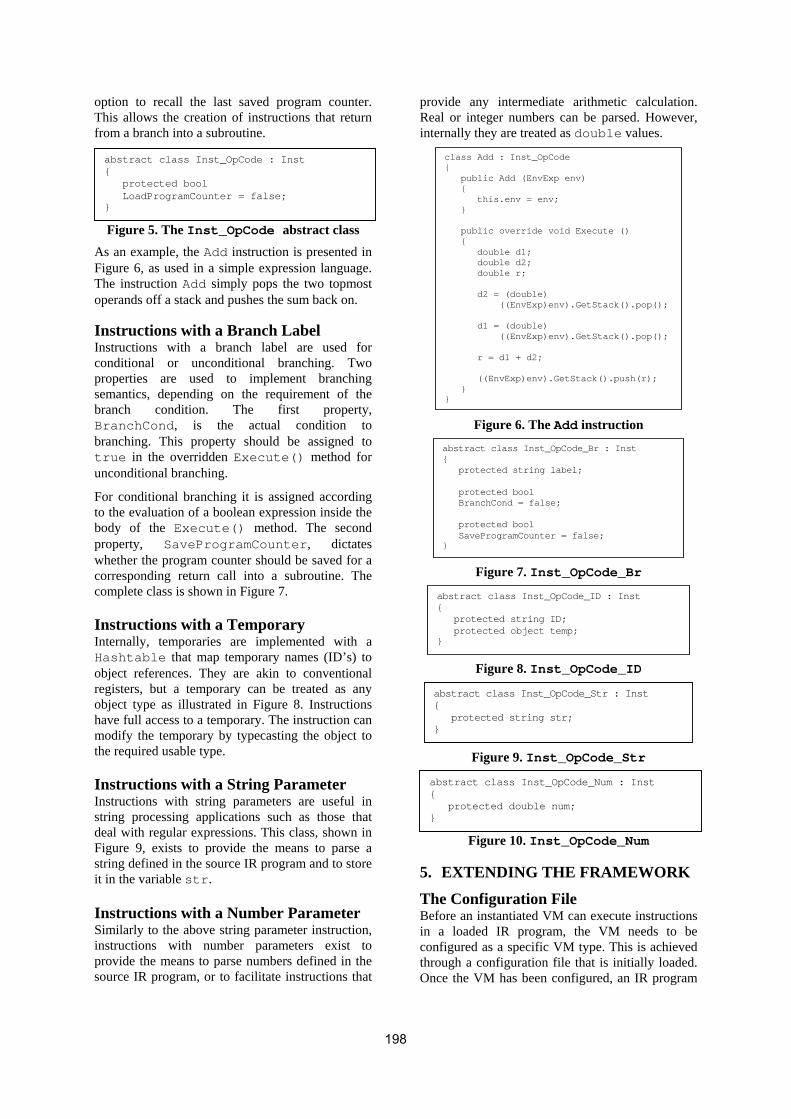
option to recall the last saved program counter. This allows the creation of instructions that return from a branch into a subroutine.
abstract class Inst_OpCode : Inst { protected bool LoadProgramCounter = false; }
Figure 5. The Inst_OpCode abstract class
As an example, the Add instruction is presented in Figure 6, as used in a simple expression language. The instruction Add simply pops the two topmost operands off a stack and pushes the sum back on.
Instructions with a Branch Label Instructions with a branch label are used for conditional or unconditional branching. Two properties are used to implement branching semantics, depending on the requirement of the branch condition. The first property, BranchCond, is the actual condition to branching. This property should be assigned to true in the overridden Execute() method for unconditional branching.
For conditional branching it is assigned according to the evaluation of a boolean expression inside the body of the Execute() method. The second property, SaveProgramCounter, dictates whether the program counter should be saved for a corresponding return call into a subroutine. The complete class is shown in Figure 7.
Instructions with a Temporary Internally, temporaries are implemented with a Hashtable that map temporary names (ID’s) to object references. They are akin to conventional registers, but a temporary can be treated as any object type as illustrated in Figure 8. Instructions have full access to a temporary. The instruction can modify the temporary by typecasting the object to the required usable type.
Instructions with a String Parameter Instructions with string parameters are useful in string processing applications such as those that deal with regular expressions. This class, shown in Figure 9, exists to provide the means to parse a string defined in the source IR program and to store it in the variable str.
Instructions with a Number Parameter Similarly to the above string parameter instruction, instructions with number parameters exist to provide the means to parse numbers defined in the source IR program, or to facilitate instructions that
provide any intermediate arithmetic calculation. Real or integer numbers can be parsed. However, internally they are treated as double values.
class Add : Inst_OpCode { public Add (EnvExp env) { this.env = env; } public override void Execute () { double d1; double d2; double r; d2 = (double) ((EnvExp)env).GetStack().pop(); d1 = (double) ((EnvExp)env).GetStack().pop(); r = d1 + d2; ((EnvExp)env).GetStack().push(r); } }
Figure 6. The Add instruction
abstract class Inst_OpCode_Br : Inst { protected string label; protected bool BranchCond = false; protected bool SaveProgramCounter = false; }
Figure 7. Inst_OpCode_Br
abstract class Inst_OpCode_ID : Inst { protected string ID; protected object temp; }
Figure 8. Inst_OpCode_ID
abstract class Inst_OpCode_Str : Inst { protected string str; }
Figure 9. Inst_OpCode_Str
abstract class Inst_OpCode_Num : Inst { protected double num; }
Figure 10. Inst_OpCode_Num
5. EXTENDING THE FRAMEWORK
The Configuration File Before an instantiated VM can execute instructions in a loaded IR program, the VM needs to be configured as a specific VM type. This is achieved through a configuration file that is initially loaded. Once the VM has been configured, an IR program
198

can be loaded and executed. The configuration file specifies the name of the class used as an environment, as well as the names of all instruction classes, both stored as .NET DLL’s. The configuration file will give the complete instruction set for a particular VM. Figure 11 gives an example configuration file for an expression language. The keyword environment is followed by an environment class name, and one environment instance will be instantiated for that class. When instructions are instantiated at program load time, the environment that will be used by the instruction is named after the using keyword.
Extending the Environments Suppose a new language is required, be it similar to an existing language, or one that features an entirely new syntax. If an existing language uses an environment with an appropriate data structure then the new language can extend the existing environment to suite its own needs. A ray-tracer language needs to render a scene onto a bitmap, but may also require a means to perform numeric calculations. Thus the EnvExp environment of the expression language can be extended with two extra data structures; a scene and a bitmap, giving rise to an EnvRT environment suitable for a ray-tracer.
Extending the Instruction Sets Instructions are extended from one of the five instruction classes mentioned earlier, to a set of concrete instruction classes instantiated at load time. Extending instruction sets with environments that are subclasses of each other, makes for a scalable framework in which to design a tailored VM for a DSL. The ray-tracer language serves as an example. The EnvRT environment is a subclass of EnvExp, so any one of the instructions operating on an EnvExp, can also operate on a EnvRT, as illustrated in the configuration file for the ray-tracer language, depicted in Figure 12.
6. BUILDING A DSL Once a defined environment and instruction set are in place, a front-end for the DSL needs to be developed. Essentially this is the task of writing a simple compiler for the DSL. This entails designing syntax for the language using compiler tools. The example DSL in this section was built using LG to define the tokens for the lexer, and PG to define the grammar for the parser. Both tools bear a familiar syntax to most commonly used industry tools. The translation of a small, functional expression language can be intuitively understood by the following illustrative example. The program in Figure 13 evaluates the expression
(* Create an instance of the *) (* expression environment. *) environment EnvExp (* Register the following expression (* instructions with the DVM. *) Push using EnvExp Store using EnvExp Load using EnvExp Sub using EnvExp Add using EnvExp Mul using EnvExp Br using EnvExp Brgz using EnvExp Nop using EnvExp Div using EnvExp (* Some generic instructions *) Call using EnvExp Ret using EnvExp Print using EnvExp
Figure 11. Example configuration file to setup the VM for a small expression language
(* Create an instance of the *) (* ray-tracer environment. *) environment EnvRT (* These instructions were part of *) (* the EnvExp environment. *) Push using EnvRT Add using EnvRT Sub using EnvRT Mul using EnvRT Div using EnvRT (* Ray-tracer specific instructions. *) LookAt using EnvRT Specular using EnvRT Diffuse using EnvRT Reflect using EnvRT Translate using EnvRT Quad using EnvRT
Figure 12. Configuration file to setup a ray-tracer language borrowing some instructions from an expression language
5,291
=+∑=
nwherein
i
…(1)
in a functional manner. The token and grammar definitions for each of the five instruction types are given in section 5, and the translated IR code for this program is shown in Figure 14 as a concrete example, that demonstrates the use of temporaries (as storage for variables n and i) and also branching instructions for the actual implementation of the summation construct.
let n = 5 in 9 + sum (i) 1..n (2 * i) end
Figure 13. Programmatic representation of the
summation expression (1) The generated IR code performs operations on a runtime stack. This stack is indeed defined as part
199
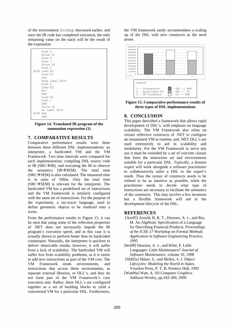
of the environment EnvExp discussed earlier, and once the IR code has completed execution, the only remaining value on the stack will be the result of the expression.
Push 5 Store $1 Push 9 Push 1 Store $2 Push 0 @100 Load $2 Load $1 Sub Brgz label @200 Push 2 Load $2 Mul Add Load $2 Push 1 Add Store $2 Br label @100 @200 Nop Add Figure 14. Translated IR program of the
summation expression (1)
7. COMPARATIVE RESULTS Comparative performance results were done between three different DSL implementations: an interpreter, a hardcoded VM and the VM Framework. Two time intervals were compared for each implementation; compiling DSL source code to IR (SRC IR), and executing the IR to observe the semantics (IR SEM). The total time (SRC SEM) is also calculated. The measured time is in units of 100ns. Only the total time (SRC SEM) is relevant for the interpreter. The hardcoded VM has a predefined set of instructions and the VM Framework is similarly configured with the same set of instructions. For the purpose of the experiment, a ray-tracer language, used to define geometric objects to be rendered onto a scene. From the performance results in Figure 15, it can be seen that using some of the reflection properties of .NET does not necessarily impede the IR program’s execution speed, and in this case it is actually shown to perform better than its hardcoded counterpart. Naturally, the interpreter is quickest to deliver observable results, however, it will suffer from a lack of scalability. The hardcoded VM will suffer less from scalability problems, as it is easier to add new instructions as part of the VM core. The VM Framework treats environments, and instructions that access these environments, as separate external libraries, or DLL’s, and they do not form part of the VM Framework’s core execution unit. Rather, these DLL’s are configured together as a set of building blocks to yield a customized VM for a particular DSL. Furthermore,
the VM framework easily accommodates a scaling up of the DSL with new constructs as the need arises.
0
5 0 0 0 0 0
1 0 0 0 0 0 0
1 5 0 0 0 0 0
2 0 0 0 0 0 0
2 5 0 0 0 0 0
3 0 0 0 0 0 0
3 5 0 0 0 0 0
4 0 0 0 0 0 0
4 5 0 0 0 0 0
5 0 0 0 0 0 0
1 2 3T i c k s ( 1 0 0 n s )
Legend 1 – Interpreter 2 – Hard-coded VM 3 - VM Framework
– SRC -> SEM – SRC -> IR - IR -> SEM
Figure 15. Comparative performance results of
three types of DSL implementations
8. CONCLUSION This paper described a framework that allows rapid development of DSL’s, with emphasis on language scalability. The VM Framework also relies on certain reflective constructs of .NET to configure an instantiated VM at runtime, and .NET DLL’s are used extensively to aid in scalability and modularity. For the VM Framework to serve any use it must be extended by a set of concrete classes that form the instruction set and environments suitable for a particular DSL. Typically, a domain expert will work alongside a software practitioner to collaboratively tailor a DSL to the expert’s needs. Thus the syntax of constructs needs to be refined to be as intuitive as possible, while the practitioner needs to decide what type of instructions are necessary to facilitate the semantics of the constructs. This may involve a few iterations but a flexible framework will aid in the development lifecycle of the DSL.
REFERENCES [Arn95] Arnold, B. R. T., Deursen, A. v., and Res,
M. An Algebraic Specification of a Language for Describing Financial Products. Proceedings of the ICSE-17 Workshop on Formal Methods Application in Software Engineering Practice, 1995
Deu98] Deursen, A. v., and Klint, P. Little Languages: Little Maintenance? Journal of Software Maintenance, volume 10, 1998
[Shl92a] Shlaer, S., and Mellor, S. J. Object Lifecycles: Modeling the World in States. Yourdon Press, P. T. R. Prentice Hall, 1992
[Wat00a] Watt, A. 3D Computer Graphics. Addison-Wesley, pp.342-369, 2000
200

Java DataSet
Markus Lorez University of Applied Sciences, Rapperswil
Oberseestrasse 10 CH – 8640 Rapperswil
Alain Schneble University of Applied Sciences, Rapperswil
Oberseestrasse 10 CH – 8640 Rapperswil
ABSTRACT
Today’s applications are required to distribute data beyond a company’s intranet and access services located all over the world. XML and Web Service technologies provide portable solutions in a heterogeneous Internet envi-ronment. Still, the data has to be interpreted according to schema definitions and transformed into an appropriate intra-application representation. The .Net DataSet can represent relational data and exchange it using the XML syntax. The XML schema used by the DataSet (DiffGram) to map data to XML is proprietary. Using the XML data as is on another platform requires additional parsing and interpretation. The goal of this project was to re-implement the .Net DataSet in Java to provide seamless interoperability between .Net Web Services using Data-Sets and Java Web Service clients/consumers. This paper discusses the need for a Java DataSet and the problems that arose during the reimplementation. Further, it summarises the Java implementation and the seamless-ness/transparency of the Java DataSet integration.
Keywords Toolkit-Interoperability, .Net Web Services, DataSet, XML, Interoperability with JavaJAX-RPC/Axis, Data-Centric Applications, Porting Components from .Net to Java
1. INTRODUCTION Almost every application needs to store data. Rela-tional databases are still the most common solution for storing information at least for data-centric busi-ness applications. These applications often directly manipulate this data and a relational representation is appropriate or even desired (e.g. to present the data in a table/grid). There is no need for a complex ob-ject oriented domain model for such applications because it will not offer any benefits – a relational model is sufficient.
Another characteristic of data-centric applications is the requirement to work with disconnected data. But working with disconnected data poses the problem of concurrent data modification. This in turn requires the application being aware of modifications done on another’s behalf.
In terms of interoperability, Web Services are cur-
rently the state-of-the-art for building distributed systems. Web Services typically use SOAP [Soa] as message protocol, which itself relies on XML. These technologies allow to access services built on one platform (e.g. .Net) to be accessed by clients built on a different platform (e.g. Java). But interoperable services have to exchange the data passed in mes-sages in a portable format as well (i.e. XML).
The Microsoft .Net platform easily allows developers to build interoperable distributed systems, because technologies such as Web Services and XML are an integral part of the framework. The framework fur-ther offers an applicable concept called DataSet. The DataSet is capable of holding an in-memory repre-sentation of relational data. It can even be used in combination with Web Services as data exchange container because it allows serialisation and deseri-alisation to and from XML.
But there is a problem when accessing a .Net Web Service using DataSets from another platform (e.g. Java), because the platform-dependent DataSet con-struct is not available. Even though DataSets use XML as serialisation format, interpreting and recon-structing the relational model is a complex, error-prone and time-consuming task.
Permission to make digital or hard copies of all or part of this work for personal or classroom use is granted without fee provided that copies are not made or distributed for profit or commercial advantage and that copies bear this notice and the full citation on the first page. To copy oth-erwise, or republish, to post on servers or to redistribute to lists, requires prior specific permission and/or a fee. .NET Technologies’2005 conference proceedings, ISBN 80-86943-01-1 Copyright UNION Agency – Science Press, Plzen, Czech Republic
This would require building interoperable .Net Web Services without DataSets. However, DataSets pro-
201

vide a practical and applicable solution and can help to solve some reoccurring problems like the concur-rency issue when working with disconnected data. Because many .Net Web Services are (and will be) built using DataSets, there is a need for an easy ac-cess to these services from another platform.
For the reimplementation of the .Net DataSet, Java 5 has been chosen because the Java Platform has proven to be a robust environment for distributed business applications as well as .Net.
Microsoft .Net DataSet The DataSet is able to hold an in-memory representa-tion of relational data. It can be compared to a rela-tional database: it allows the definition of a relational schema (tables, columns) and the storage of data ac-cording to this schema. The DataSet even supports constraints (i.e. unique/foreign key constraints and allow/deny DBNull values). This makes it an ideal replacement for a domain model in data-centric ap-plications. The DataSet is meant to be passed through different software layers, from the data access up to the user interface layer. The .Net framework supports this approach by offering classes that enable two-way communication between the DataSet and database. Further, a DataSet can directly be bound to user in-terface components supporting data binding (e.g. to a table/grid). What makes the DataSet such a usable data container for disconnected data is its capability to store differ-ent versions of the data (i.e. original, current and proposed). It thus implements some kind of unit of work pattern [Fow02], because it allows a client to modify data and retransmit the modified DataSet back to the server once all update operations are completed by the client. By including the original data as well, it can easily be determined which data were already modified by another client in the mean-time. When DataSets are used in WebServices, they are passed as XML payload including both the schema and the data. The schema is described by an (ex-tended) XML Schema. The data is represented by an XML grammar called DiffGram, which supports the representation of current and original data as well as error information concerning the data.
2. JAVA DATASET As described earlier, a platform-independent imple-mentation of the .Net DataSet is highly desirable. Actually, there are two different possible ways to reach this goal. The first alternative would be to port the DataSet (or the .Net framework in its entirety) to different native platforms resulting in a number of
several platform-dependent versions. In fact, this approach is already realised to some extent by the Mono project [Mon]. The second alternative would be to port the DataSet once to a platform-independent framework, such as Sun’s Java. The latter approach is the ultimate goal of the Java Data-Set project.
Goal On a lower level, there are several goals and re-quirements for a DataSet reimplementation in Java. Since the project was limited to 16 weeks, the de-sired functionality had to be adapted to that time re-striction. We included everything that is essential to use the DataSet in a client. This includes the components of the relational data model (such as tables, rows, col-umns, constraints and relations), row state handling, (XML-) serialisation and deserialisation and the GetChanges method. Other DataSet components, however, are not vital in client use (such as Data-Views or DataAdapters). Since most developers who implement a Java client using DataSets are familiar with the .Net DataSet, the syntax should be as near as possible to Microsoft’s DataSet. Luckily, C# and Java (especially version 5.0) are quite similar except for a few language con-cepts. Another requirement was that the installation of the Java DataSet library should be kept as simple as pos-sible. Therefore, third-party libraries should be avoided. The Java DataSet itself uses no additional libraries. For Web Service access, however, Apache Axis is used.
Implementation Before porting a highly complex construct – such as the .Net DataSet – to another platform, thorough analysis of the original is indispensable. Unfortu-nately the (otherwise very good) documentation by Microsoft is only helpful to some extent because it is designed to help application developers using the DataSet. It is not suited, though, to support a devel-oper intending to dissect the DataSet’s internals and re-implement it on another platform. As a conse-quence, the DataSet’s internal mechanics must be discovered by other means, such as own tests or even analysis of the IL code (Intermediate Language, comparable to the ByteCode of Java). Once these difficulties have been overcome, the im-plementation of the Java DataSet is quite straight-forward. The major differences to the original are due to the divergence of the Java and C# languages and their frameworks, respectively. One important difference in usage is the direct invocation of getter and setter methods in Java. Java properties are
202

SOAP-Envelope
Body
Operation Name
Parameters
Input Parameter 1:
<soap:Envelope xmlns:soap="..." ...> <soap:Body> <UpdateAccounts xmlns="..."> <AccountsParameter>
<xs:schema id="AccountsDataSet" ...> <xs:element name="AccountsDataSet" msdata:IsDataSet="true"> <!-- Accounts DataSet schema definition --> </xs:element> </xs:schema>
<diffgr:diffgram ...> <!-- account data --> </diffgr:diffgram>
</AccountsParameter> </UpdateAccounts> </soap:Body </soap:Envelope>
Figure 2. SOAP message transmitting a DataSet as operation parameter.
merely a naming convention as opposed to being built into the language itself as in C#. When it comes to porting software to a different plat-form there is a regular issue: data types. It is a pecu-liarity of the Java framework that there are no un-signed data types. Therefore, one has to implement a custom mapping mechanism to map the upper half of the unsigned C# data type’s range to the negative part of the corresponding Java type, leading to a fair amount of additional complexity. The simpler ap-proach used in the Java DataSet is to use the next bigger type class, allowing the whole unsigned value range to fit smoothly into the positive half of the Java type. Third issues are access modifiers (public, protected, internal, private). In C#, access scope is based on assembly structure whereas logical grouping is pro-vided by namespaces. As a consequence, access scope and logical grouping are orthogonal. In Java, both access scope and logical grouping are realised by packages. In the DataSet, the different classes collaborate tightly by calling members of other DataSet library classes, which implies that all classes must be located in the same package (resulting in a rather large package).
Outlook The Java implementation is far from complete. As mentioned above, there are several components in the original Microsoft DataSet that are not yet im-plemented in the Java port. However, for now it is possible to use the DataSet as a general data (trans-port) container as well as in Web Service to client communications. Additionally, there is a usage scenario of the Java DataSet in Java GUI applications. Since the DataSet provides a tabular data structure, it is an ideal table model providing data values to a JTable. Only an additional small intermediate layer between DataSet and JTable would be necessary, resulting in a setup similar to the combination DataSet/DataGrid in .Net.
3. CONSUMING .NET WEB SERVICES FROM JAVA .Net Web Services rely on SOAP1 as XML message protocol. SOAP is currently wide-accepted and there are many implementations available. In Java, most “RPC-oriented” implementations follow the APIs and conventions defined by JAX-RPC [Jax]. A feasi-ble SOAP implementation conforming to JAX-RPC is Axis [Axi]. Using Axis, a Java client can consume a (.Net) Web Service without problems as long as standard data types (like xs:string) are used as in-put/output parameters for Web Service operations. Using custom data types (like DataSets) poses some problems: a custom serialisation and deserialisation has to be implemented and the SOAP implementa-tion needs to be extended to offer transparent usage.
Passing DataSets in SOAP Messages A common approach to building a .Net Web Service that uses DataSets as data exchange containers is to follow the RPC-oriented invocation style2. For ex-ample, an operation could involve updating the data-base to reflect the modified data contained in a Data-Set. This means that DataSets have to be passed to the Web Service as operation parameter (or returned as the operation's return value). Figures 1 and 2 show an example of an RPC-oriented SOAP Message – emitted by a .Net Web Service client – containing a
1 Since SOAP Version 1.2, the term SOAP has two expan-
sions – Service Oriented Architecture Protocol and Sim-ple Object Access Protocol – to reflect the different ways in which the technology can be interpreted.
2 .Net by default uses “Document” as message and “Lit-eral” as serialisation format [Rpc]. This paper uses the term RPC-oriented independently of the underlying mes-sage format because “Document” is a superset of “RPC” and it can also be used to mimic an RPC-oriented invoca-tion style – which in fact is what .Net does by default.
Serialized DataSet SchemaSerialized DataSet Data
Figure 1. SOAP-Envelope of an RPC-oriented operation call with a DataSet as operation
parameter.
203
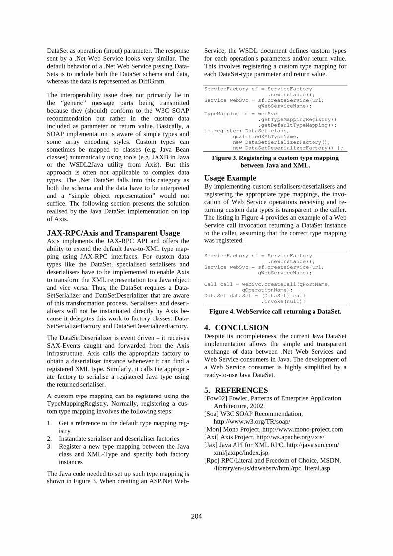
DataSet as operation (input) parameter. The response sent by a .Net Web Service looks very similar. The default behavior of a .Net Web Service passing Data-Sets is to include both the DataSet schema and data, whereas the data is represented as DiffGram.
The interoperability issue does not primarily lie in the “generic” message parts being transmitted because they (should) conform to the W3C SOAP recommendation but rather in the custom data included as parameter or return value. Basically, a SOAP implementation is aware of simple types and some array encoding styles. Custom types can sometimes be mapped to classes (e.g. Java Bean classes) automatically using tools (e.g. JAXB in Java or the WSDL2Java utility from Axis). But this approach is often not applicable to complex data types. The .Net DataSet falls into this category as both the schema and the data have to be interpreted and a “simple object representation” would not suffice. The following section presents the solution realised by the Java DataSet implementation on top of Axis.
JAX-RPC/Axis and Transparent Usage Axis implements the JAX-RPC API and offers the ability to extend the default Java-to-XML type map-ping using JAX-RPC interfaces. For custom data types like the DataSet, specialised serialisers and deserialisers have to be implemented to enable Axis to transform the XML representation to a Java object and vice versa. Thus, the DataSet requires a Data-SetSerializer and DataSetDeserializer that are aware of this transformation process. Serialisers and deseri-alisers will not be instantiated directly by Axis be-cause it delegates this work to factory classes: Data-SetSerializerFactory and DataSetDeserializerFactory.
The DataSetDeserializer is event driven – it receives SAX-Events caught and forwarded from the Axis infrastructure. Axis calls the appropriate factory to obtain a deserialiser instance whenever it can find a registered XML type. Similarly, it calls the appropri-ate factory to serialise a registered Java type using the returned serialiser.
A custom type mapping can be registered using the TypeMappingRegistry. Normally, registering a cus-tom type mapping involves the following steps:
1. Get a reference to the default type mapping reg-istry
2. Instantiate serialiser and deserialiser factories 3. Register a new type mapping between the Java
class and XML-Type and specify both factory instances
The Java code needed to set up such type mapping is shown in Figure 3. When creating an ASP.Net Web-
Service, the WSDL document defines custom types for each operation's parameters and/or return value. This involves registering a custom type mapping for each DataSet-type parameter and return value.
ServiceFactory sf = ServiceFactory .newInstance(); Service webSvc = sf.createService(url, qWebServiceName);
TypeMapping tm = webSvc .getTypeMappingRegistry() .getDefaultTypeMapping(); tm.register( DataSet.class, qualifiedXMLTypeName, new DataSetSerializerFactory(), new DataSetDeserializerFactory() );
Figure 3. Registering a custom type mapping between Java and XML.
Usage Example By implementing custom serialisers/deserialisers and registering the appropriate type mappings, the invo-cation of Web Service operations receiving and re-turning custom data types is transparent to the caller. The listing in Figure 4 provides an example of a Web Service call invocation returning a DataSet instance to the caller, assuming that the correct type mapping was registered.
ServiceFactory sf = ServiceFactory .newInstance(); Service webSvc = sf.createService(url, qWebServiceName);
Call call = webSvc.createCall(qPortName, qOperationName); DataSet dataSet = (DataSet) call .invoke(null);
Figure 4. WebService call returning a DataSet.
4. CONCLUSION Despite its incompleteness, the current Java DataSet implementation allows the simple and transparent exchange of data between .Net Web Services and Web Service consumers in Java. The development of a Web Service consumer is highly simplified by a ready-to-use Java DataSet.
5. REFERENCES [Fow02] Fowler, Patterns of Enterprise Application
Architecture, 2002. [Soa] W3C SOAP Recommendation,
http://www.w3.org/TR/soap/ [Mon] Mono Project, http://www.mono-project.com [Axi] Axis Project, http://ws.apache.org/axis/ [Jax] Java API for XML RPC, http://java.sun.com/
xml/jaxrpc/index.jsp [Rpc] RPC/Literal and Freedom of Choice, MSDN,
/library/en-us/dnwebsrv/html/rpc_literal.asp
204


![[Ronald Syme] Tacitus Vol. 1(BookFi.org)](https://img.dokumen.tips/doc/110x75/563db9f4550346aa9aa169a0/ronald-syme-tacitus-vol-1bookfiorg.jpg)