Embed Size (px)
Citation preview

© AESS Publications, 2011 Page 228
Journal of Asian Scientific Research, 1 (5), pp.229-246 2011

© AESS Publications, 2011 Page 229
Journal of Asian Scientific Research, 1 (5), pp.229-246 2011
Introduction
When a bar is hit by a hammer, clear sound can be heard because the bar vibrates at resonant frequency. If the bar is oscillated at this resonant frequency, it will be found that the vibration amplitude of the bar becomes very large. Therefore, when a machine is designed, it is important to know the resonant frequency of the machine. The analysis to obtain the resonant frequency and vibration mode of an elastic body is called "mode analysis". The problem of vibration of a beam is of intrinsic interest because the beam represents the simplest of all engineering structural. The subject of vibrations is of fundamental importance in engineering and technology. Discrete modeling is sufficient to understand the dynamics of many vibrating systems; however a large number of vibration phenomena are far more easily understood when modeled as continuous systems. Dynamics and analysis techniques for a wide range of continuous systems Present including strings, bars, beams, membranes, plates, fluids and elastic bodies in one, two and three dimensions. The vibrations of elastic structures such as strings, beams, and plates can be described in terms of waves traveling in waveguides (Cremer, L., Heckl, M., Ungar, E. E & Graff, K. F). Although the subject of wave motions has been received more attentions in the fields of acoustics in
fluids and solids than mechanical vibrations of elastic structures, wave analysis techniques have been employed to reveal important physical characteristics associated with vibrations of elastic structures. One advantage of the wave analysis technique is its compact and systematic approach to analyze complex structures such as trusses, aircraft panels with periodic supports, and beams on multiple supports( Lin, Y. K. &, Yong, Y). Applying the concept of wave reflection and transmission, (Mace, B. R) obtains the frequency equations of Euler– Bernoulli beams including both propagating and attenuating waves. By the phase-closure principle,( Mead, D. J.) determined natural frequencies of Euler–Bernoulli beams. Based on the same principle, (Tan, C. A., & Kang, B.) presented a systematic approach to the free vibration analysis of a rotating Timoshenko shaft with multiple bearing supports, and (Kang, B., Riedel, C. H., & Tan, C. A.) studied the free vibrations of a multi-span, extensional curved beam. The classical method, known as the normal mode or eigenfunction expansion, of solving the forced vibration problem of a distributed parameter system involves expansion of the forcing function into the eigenfunctions of the associated free vibration problem. While this method is theoretically sound and powerful, the method is difficult to implement when the problem to be solved is a nonself-adjoint
Effect of Dimension and Supported End on Natural Frequency of Rectangular Beam
Abstract
Author
Ayad Arab Ghaidan University of Kirkuk, Collage of Engineering, Petroleum Department, Iraq. E-mail: [email protected]
Keywords: Natural frequency, Mode, finite element, Flexural stiffness, end beams conditions.
The effect of natural frequency in dynamic load is an important factor because when the natural frequency is small or closed to zero the beam goes to failure. In this paper the theoretical, finite element and experimental models are presented to explain the effect of dimension and supported end on the beam, when the beam is fixed end the natural frequency and it's rate are higher than simple supported end and then free end, and the natural frequency is increase when the dimension, specific mass, and square root of flexural stiffness per mass (EI/M) are of the beam increase, so that when the beam end is fixed and has big size the beam resistant the failure. Experimental results show the Damping has very little effect on natural frequency of the beam, and hence the calculations for natural frequencies are generally made on the basis of no damping in beam.
© AESS Publications, 2011 Page 230
Journal of Asian Scientific Research, 1 (5), pp.229-246 2011
system typically due to complicating effects such as damping, discontinuities, or nonclassical boundary conditions, in which case obtaining the exact eigensolutions is not often feasible. As an alternative approach to solve forced vibration problems, (Yang, B., and Tan, C. A.) presented a method for evaluating exact closed form transfer functions for a class of one-dimensional distributed parameter systems. Applying the energy functional of constrained and combined damped systems, (Yang, B.) presented a method to obtain a closed-form transient response solution in eigenfunction series for a distributed damped system. An augmented energy formulation is introduced to regain symmetry for the spatial differential operator which is destroyed in the original equation of motion by the constraints.
The modeling of a transversely vibrating beam includes the effects of shear distortion and bending moment, shear distortion effects was first including by the modeling by S. Timoshenko (Haym Benaroya), and therefore his name is attached to such models. The vibration of a beam with an overhang of arbitrary length is investigated numerically, an approximate formula for small overhang is proposed, and the results are compared, The approximation, valid for a simply-supported vibrating beam with small overhang, can be used to compute a beam’s flexural stiffness EI from measured frequency f, measured geometry, S, L, and measured weight W and would result in a conservative estimate of EI. The beam’s modulus of elasticity E can be computed if I is known (Murphy J. F). The formulation and basic solutions will be studied along with simple boundary conditions in this search. The Laplace transform has used to solve the exact solution for uniform beam with different dimensions and it's compare with finite element solution presenting Ansys programming and experimental data.
Theory
Derivation of the Equations of motion for the beam with shear distortion (the Timoshenko Beam), the equation governing the transverse vibration of the beam length L, with the following properties at section x; m(x) is the mass per unit length, A(x) is the cross-sectional area, and I(x) is the moment of inertia, Assume small deflections y(x,t) and rotations
, and include the bending M(x,t) and shear
Q(x,t) effects. Consider a free body of a section of length dx. For free vibration the external loading p(x,t) equal to zero. Basic Bernoulli- Euler beam equation that is used many simplified studies (Haym Benaroya), and then the equation of motion is
…………………...(1)
Where I is the moment of inertia and M is the mass per unit length(specific mass), and let
………………………….(2)
Where is the natural frequency, Gives
………………………………..(3)
Where
…………………………… ……(4)
The solution is approached utilizing the Laplace transform. Is gotten
……………………………….…..(5)
Thus
…………………………………..….(6)
Tacking the inverse transformation yields
………...(7)
Where

© AESS Publications, 2011 Page 231
Journal of Asian Scientific Research, 1 (5), pp.229-246 2011
A( ……..…….(8)
B( (sinh ……………..(9)
C( …………..(10)
D( ……..…….(11)
Note that A(0)=1, B(0)=0, C(0)=0, and D(0)=0, for application to specific boundary conditions, the derivative of Equation (7), they are given in the following.
`
………..(12)
……………..(13)
…………….(14)
1. Fixed-Free ends
From Equations ( 5 ) and (6 ). The boundary conditions for the clamped end at x=0 as
…………………………(15)
…………………………….(16)
And at the free end (x=L) as
……………………….(17)
………………………..(18)
Substituting strain-displacement relations and substituting Equation (2) gives.
…………………………..(19)
……………………………..(20)
……………………………(21)
……………………………(22)
Substituting Equations (7 ) and (12) to (14) in these conditions gives
….. (23)
……(24)
Or
…. (25)
Since
…………………………(26)
It must be that
……………..(27)
Or
…………(28)
Substituting Equations ( 8 ) to ( 11 ) gives
(29)
The roots of this equation are

© AESS Publications, 2011 Page 232
Journal of Asian Scientific Research, 1 (5), pp.229-246 2011
..(30) from Equation ()
………………………(31)
Where E is young modulus. The natural mode is given by Equation (7).
32
From Equation (25), is gotten
…………..(33)
Thus
..(34)
The mode shape is determined by the bracketed quantity. The magnitude of the coefficient
…………………………………….(35)
is arbitrary as far as the mode shape is concerned and is a function of the excitation.
2. Fixed-Fixed ends
From Equations (5) and (6). The boundary conditions for the clamped ends at x=0, and x=L as
…………………………(36)
…………………………….(37)
…………………………(38)
…………………………….(39)
Substituting strain-displacement relations and substituting Equation (2) gives.
…………………………..(40)
……………………………..(41)
…………………………..(42)
…………………………………..(43)
Substituting Equations ( 7 ) and ( 12 ) in these conditions gives
….(44)
…….(45)
Or
..….(46)
Since
……………………………(47)
It must be that
……………….(48)
Or
………..(49)
© AESS Publications, 2011 Page 233
Journal of Asian Scientific Research, 1 (5), pp.229-246 2011
The roots of this equation are
.(50)
The natural mode is given by Equation (7).
(51)
From Equation (46)
…………….(52)
Thus
(53)
The mode shape is determined by the bracketed quantity.
3. Hinged-Hinged ends.
From Equations (7) and (13). The boundary conditions for the clamped end at x=0 as
…………………………..(54)
……………………………(55)
And at the free end (x=L) as
………………………….(56)
………………………….(57)
Substituting strain-displacement relations and substituting Equation (2) gives.
…………………………….(58)
…………………………….(59)
…………………..…………(60)
…………………………….(61)
Substituting Equations (7 ) and (13) in these conditions gives
……..(62)
………(63)
Or
…(64)
Since
………………………(65)
It must be that
……………(66)
Or
………….(67)
0r
………………(68)
Since λ

© AESS Publications, 2011 Page 234
Journal of Asian Scientific Research, 1 (5), pp.229-246 2011
This equation reduces to
Or
And
……………………..(69)
(70)
And
From Equation ( 66 )
……………( 67)
And equation (67 ) becomes
…………………. (68)
4. Fixed-Hinged ends
From Equations (7), (12) and (13). The boundary conditions for the clamped end at x=0 as
……………………….. (69)
………………………… (70)
And at the free end (x=L) as
………………………..(71)
……………………..(72)
Substituting strain-displacement relations and substituting Equation (2) gives.
………………………..(73)
………………………….(74)
…………………………..(75)
…………………………(76)
Substituting Equations ( 7 ) and ( 12 ) to ( 13 ) in these conditions gives
…….(77)
…..(78)
Or
….(79)
Since
…………………………(80)
It must be that
……………(81)
Or
………..(82)
Substituting Equations ( ) to ( ) gives
.(83)

© AESS Publications, 2011 Page 235
Journal of Asian Scientific Research, 1 (5), pp.229-246 2011
The roots of this equation are
(84) from Equation (4)
…………………………….(85)
The natural mode is given by Equation (7).
86)
From Equation ( )
……………(87)
Thus
.(88)
From above equations, the effect of dimension (b/a), specific mass (M)( Kilogram per length Kg/m) and flexibly per mass (EI/M)( Pascal meter to power five per kilogram pa.m5/Kg) on the natural frequency for Al- beam are studied, proprieties and dimension of Al- beam is shown in table (1)
Finite element
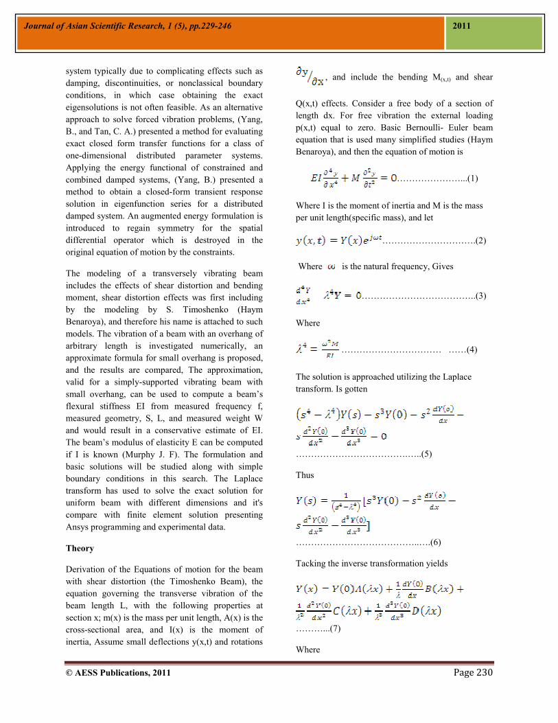
It is said that there are two methods for mode analysis. One is the theoretical analysis and the other is the finite element method (FEM). Theoretical analysis is usually used for a simple shape of an elastic body, such as a flat plate and straight bar, but theoretical analysis cannot gives us the vibration mode for complex shape of an elastic body. FEM analysis can obtain the vibration mode for it. In FEM analysis, it is important to select a proper element type which influences the accuracy of solution, working time for model construction, and
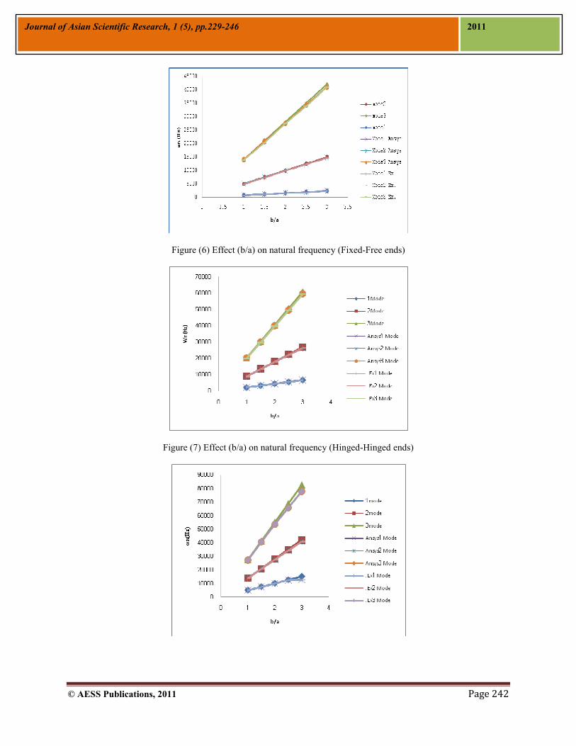
CPU time, the two dimensional elastic beam is selected for the following reasons, (a) vibration mode is constrained in the two dimensional plane, (b) Number of elements can be reduced; the time for model construction and CPU time are both shortened (Zienkiewicz O.C., CBE, FRS). Two-dimensional elastic beam has three degree of freedom at each node (i, j), which are translator deformations in x and y directions and rotational deformation around the z axis. This beam can be subjected to extension or compression bending due to its length and the magnitude of the area moment of inertia of its cross section. A mapped mesh consisting of beam (ANSYS element type 2D elastic) is used two dimensional modeling of solid structures Figure (1). The numbers of divisions are equal to 20. To study natural frequency, Aluminum alloy have taken with four boundary conditions. Figures from (2) to (5) are shown the natural frequency and modes of the Al alloy. Experimental Setup Free vibration takes place when a system oscillates under the action of forces inherent in the system itself due to initial disturbance, and when the externally applied steady-state forces are absent. The experimental setup is consists of an Aluminum beams. Different combinations of beam geometries for each of the beam material are used with supported condition. Transducers (strain gauge, accelerometer), a data-acquisition system and a computer with signal display and processing software. Accelerometer is a sensing element (transducer) to measure the vibration response (i.e., acceleration, velocity and displacement). Data acquisition system takes vibration signal from the accelerometer and encode it I digital form. Computer acts as a data storage and analysis system, it takes encoded data from data acquisition system and after processing it display on the computer screen by using analysis software and then Determine at least the three experimental natural frequencies from the frequency-domain plot Results and Discussion Figure (6, 7, 8, 9) show the comparison between theoretical solution, finite element and experimental solution with different support conditions, Fixed-Free ends, Hinged-Hinged ends, Fixed-Fixed ends, and Fixed-Hinged ends respectively for Al- alloy beam with different size b/a ( where b is the height of beam and a is a width) equal to (1, 1.5, 2, 2.5, 3) with constant length equal to (0.254m). It can be seen from comparison that the natural frequency is high when the beam is fixed end than hinged end than

© AESS Publications, 2011 Page 236
Journal of Asian Scientific Research, 1 (5), pp.229-246 2011
free end and the natural frequency is increase with increase the ratio (b/a). Figures (10, 11, 12, and 13) show the effect of specific mass (M)(Kg/m) of beam on the natural frequency. It can be seen from comparison that the natural frequency is higher when the beam is fixed end than hinged end than free end and the natural frequency is increase with increase the specific mass of beam. The effects of square root of flexural stiffness per mass (EI/M)( pa.m5/Kg) on the natural frequency are shown in Figures (14, 15, 16, and 17). It can be seen from comparison that the natural frequency is higher when the beam fixed end than hinged end than free end and the natural frequency is increase with increase the square root of flexural stiffness (EI) per mass (M). The rate of increase of natural frequency is higher in fixed end of the beam than hinged end than free end of the beam with increase the dimension of the beam. Results of theoretical solution, finite element, and Experimental are much closed. It can be seen theoretical results are higher than finite element results, and finite element results are higher than Experimental results because the beam, in actual practice, there is always some damping. References Cremer, L., Heckl, M., and Ungar, E. E. (1973),
"Structure-Borne Sound", Springer, Berlin.
Graff, K. F.(1975) "Wave Motion in Elastic Solids",
Ohio State University Press, Columbus, OH.
Haym Benaroya, and Mark L. Nagurka
"mechanical vibration, analysis, Uncertainties, and
Control", third edition.
Kang, B., Riedel, C. H., and Tan, C. A.(2003)
“Free Vibration Analysis of Planar Curved Beams by
Wave Propagation,” J. Sound Vib., Vol.260, pp. 19–
44.
Lin, Y. K.(1962) “Free Vibration of a Continuous
Beam on Elastic Supports,” Int. J. Mech. Sci.,Vol. 4,
pp. 409–423.
Mace, B. R..( 1984) “Wave Reflection and
Transmission in Beams,” J. Sound Vib., Vol.97, pp.
237–246
Mead, D. J.(1994) “Waves and Modes in Finite
Beams: Application of the Phase-Closure Principle,”
J. Sound Vib., Vol.171, pp. 695–702.
Murphy J. F.(1997)"Transverse Vibration of a
Simply Supported Beam with Symmetric Overhang
of Arbitrary Length", Journal of Testing and
Evaluation, JTEVA Vol. 25, No. 5, PP.522-524.
Tan, C. A., and Kang, B.(1999) “Free Vibration of
Axially Loaded, Rotating Timoshenko Shaft Systems
by the Wave-Train Closure Principle,” Int. J. Solids
Struct., Vol.36, pp. 4031–4049.
Yang, B. (1996) “Closed-Form Transient Response
of Distributed Damped Systems, Part I: Modal
Analysis and Green’s Function Formula,” ASME J.
Appl. Mech., Vol.63, pp. 997–1003.
Yang, B.(1996)“Closed-Form Transient Response of
Distributed Damped Systems, Part II: Energy
Formulation for Constrained and Combined
Systems,” ASME J. Appl. Mech.,Vol. 63, pp. 1004–
1010.
Yang, B., and Tan, C. A.(1992) “Transfer Functions
of One-Dimensional Distributed Parameter Systems,”
ASME J. Appl. Mech.,Vol. 58, pp. 1009–1014.
Yong, Y., and Lin, Y. K.(1989) “Propagation of
Decaying Waves in Periodic and Piecewise Periodic
Structures of Finite Length,” J. Sound Vib., Vol.129,
pp.99–118.
Zienkiewicz O.C. and Tylor R. L.(2005)"The Finite
Element Method for Solid and Structural Mechanics".
Sixth edition.
© AESS Publications, 2011 Page 237
Journal of Asian Scientific Research, 1 (5), pp.229-246 2011
Appendix
Figure (1) two-dimensional beam element
(a)
(b)

© AESS Publications, 2011 Page 238
Journal of Asian Scientific Research, 1 (5), pp.229-246 2011
(c)
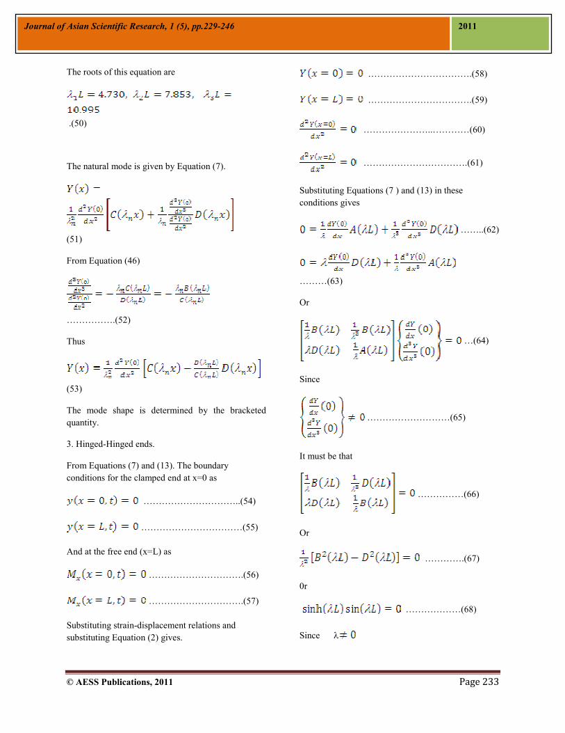
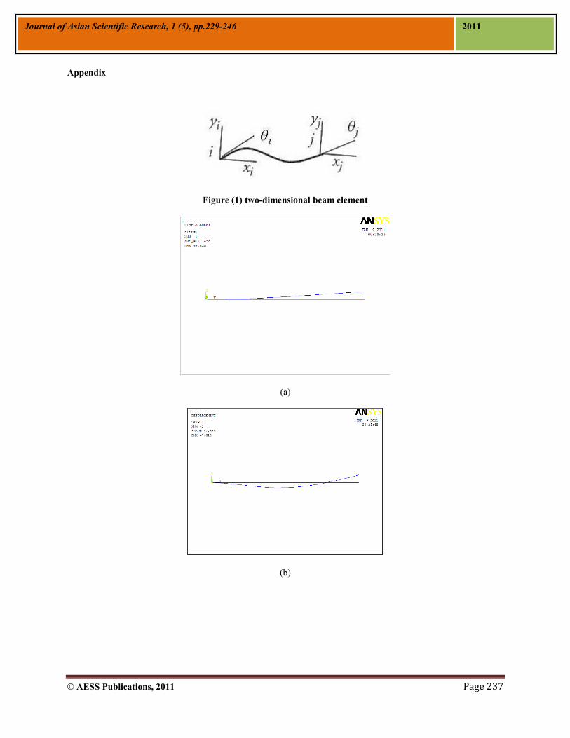
Figure (2) Natural frequency for fixed-Free ends Al-Alloy beam, (a) Mode1, (b) Mode2, (c) Mode3.
(a)

© AESS Publications, 2011 Page 239
Journal of Asian Scientific Research, 1 (5), pp.229-246 2011
(b)
(c)
Figure (3) Natural frequency for Hinged-Hinged ends Al-Alloy beam, (a) Mode1, (b) Mode2, (c) Mode3.
(a)
© AESS Publications, 2011 Page 240
Journal of Asian Scientific Research, 1 (5), pp.229-246 2011
(b)
(c)
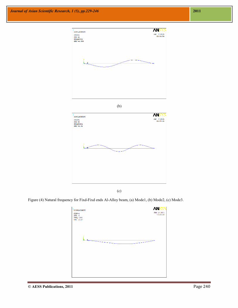
Figure (4) Natural frequency for Fixd-Fixd ends Al-Alloy beam, (a) Mode1, (b) Mode2, (c) Mode3.

© AESS Publications, 2011 Page 241
Journal of Asian Scientific Research, 1 (5), pp.229-246 2011
(a)
(b)
(c)
Figure (5) Natural frequency for Fixed-Hinged ends Al-Alloy beam, (a) Mode1, (b) Mode2, (c) Mode3
© AESS Publications, 2011 Page 242
Journal of Asian Scientific Research, 1 (5), pp.229-246 2011
Figure (6) Effect (b/a) on natural frequency (Fixed-Free ends)
Figure (7) Effect (b/a) on natural frequency (Hinged-Hinged ends)

© AESS Publications, 2011 Page 243
Journal of Asian Scientific Research, 1 (5), pp.229-246 2011
Figure (8) Effect (b/a) on natural frequency (Fixed-Fixed ends)
Figure (9) Effect (b/a) on natural frequency (Fixed-Hinged ends)
Figure (10) Effect specific mass on natural frequency (Fixed-Free ends)
Figure (11) Effect specific mass on natural frequency (Hinged-Hinged ends)

© AESS Publications, 2011 Page 244
Journal of Asian Scientific Research, 1 (5), pp.229-246 2011
Figure (12) Effect specific mass on natural frequency (Fixed-Fixed ends)
Figure (13) Effect specific mass on natural frequency (Fixed-Hinged ends)
Figure (14) Effect square root of flexural stiffness per mass (EI/M) on natural frequency (Fixed-Free ends)

© AESS Publications, 2011 Page 245
Journal of Asian Scientific Research, 1 (5), pp.229-246 2011
Figure (15) Effect square root of flexural stiffness per mass (EI/M) on natural frequency (Hinged-Hinged ends)
Figure (16) Effect square root of flexural stiffness per mass (EI/M) on natural frequency (Fixed-Fixed ends)
Figure (17) Effect square root of flexural stiffness per mass (EI/M) on natural frequency (Fixed-Hinged ends)

© AESS Publications, 2011 Page 246
Journal of Asian Scientific Research, 1 (5), pp.229-246 2011
Table (1) properties and dimension of Aluminum beam
a (m) b/a L
(m) I(m4)*10-10 Ρ (Kg/m3)
E (Mpa)
M (Kg/m)
1 0.01 1 0.254 8.33 2700 70 0.27 2 0.01 1.5 0.254 28.1 2700 70 0.405 3 0.01 2 0.254 66.7 2700 70 0.54 4 0.01 2.5 0.254 130 2700 70 0.675
5 0.01 3 0.254 225 2700 70 0.81

© AESS Publications, 2011 Page 247
Journal of Asian Scientific Research, 1 (5), pp.229-246 2011