Embed Size (px)
Citation preview

JOSHCO Lombardy East Housing Development
Electrical Technical Specification Document (External)
JOSHCO
1 November 2014
Reference: 110548
Project 110548 JOSHCO Lombardy East Housing Development Specifications1 November 2014 Page i
Contents 1 GENERAL 1
1.1. Scope 1
1.2. Normative References 1
1.3. Deviation from Specification 2
1.4. Material 3
2 LOCAL ELECTRICAL SUPPLY AUTHORITIES 3
3 CONTRACTOR'S RESPONSIBILITY 3
4 RETICULATION MV NETWORK 4
4.1. Medium Voltage Cable Network 4
4.2. Medium Voltage Joints and Terminations 4
4.3. Miniature Substations 5
4.4. Miniature Substation Plinth 6
5 LOW VOLTAGE NETWORK 6
5.1. Low Voltage Distribution Kiosks 6
5.2. Area Lighting Low Voltage Kiosks 8
5.3. Low Voltage Distribution Cables 9
5.4. Low Voltage Terminations 9
5.5. Area Lighting 9
6 CABLE TRENCHING AND INSTALLATIONS 10
6.1. Cable Sleeve Pipes 11
6.2. Concrete Slabs 11
7 EARTHING 12
8 MAINTENANCE AND OPERATING MANUALS 12
9 MARKING AND LABELLING 12
10 COMMISSIONING 12
11 TESTING 12
12 DRAWINGS 13
13 CLEANING OF SITE 13
Project 110548 JOSHCO Lombardy East Housing Development Specifications 1 November 2014 Page 1
1 GENERAL
1.1. Scope
This section covers technical specifications for the electrical part of the works and consequently describes the supply, installation and commissioning of the electrical equipment required.
1.2. Normative References
All standards, specifications and drawings referred to in this document are subject to revision and must ensure that the most recent edition of the documents listed below is applied.
City Power Specifications, Standards and Drawings
CP_TSSPEC_001: Specification for 11 kV and 22kV paper and XLPE cables SANS 1339.
CP_TSSPEC_002: Specification for low voltage insulated wire, power and multi-core control cables.
CP_TSSPEC_005: Specification for 11 kV Type ‘B’ miniature substation with rating not exceeding 1000 kVA.
CP_TSSPEC_017: Specification for miniature circuit breakers.
CP_TSSPEC_018: Specification for moulded case circuit breakers.
CP_TSSPEC_023: Specification for mechanical torque shear connectors.
CP_TSSPEC_027: Specification for concrete plinths
CP_TSSPEC_028: Specification for earth leakage circuit breakers.
CP_TSDRRAW_036: Mini-substation earthing for MV system with continuous earthing conductor to source substation.
CP__TSSPEC_053: Specification for accessories for medium voltage power cables for systems with nominal voltages of 11 kV to 33 kV.
CP__TSSPEC_054: Cable jointing kits for power and control cables with rated voltage 600/1000 V.
CP_TSSPEC_063: Specification for electronic single and three phase kilowatt hour meters.
CP_TSSPEC_078: Specification for notices, danger and warning signs.
CP_TSSPEC_084: Specification for concrete MV cable route markers.
CP_TSSPEC_087: Specification for single phase and three phase prepayment meters.
CP_TSSPEC_134: Specification for flexible protective PVC sleeves for underground drilling.
CP_TSSPEC_208: Specification for low voltage service protective distribution kiosk.
CP_TSSTAN_009: Township electrical reticulation standard for underground systems.
CP_TSSDRAW_067: Plinths for ground mounted low voltage distribution protective kiosk.

Project 110548 JOSHCO Lombardy East Housing Development Specifications 1 November 2014 Page 2
CP_TSPROC_014
CP_TSPROC_003
CP_TSPROC_028
CP_TSCHECK_037: Mini substation pre-commissioning planning checklist
CP_TSCHECK_039: Commissioning checklist for cable installation
CP_TSCHECK_043: SDB’s for underground networks
SANS & SABS
SANS IEC 60947-4: Low voltage switchgear and control
SABS 1777: Photoelectric control units for lighting (PECUs).
SANS1507: Electric cables with extruded solid dielectric insulation for fixed installations (300/500 V to 1 900 / 3 300 V).
SANS 10225: The design and construction of lighting masts.
SANS 60598 – Part 1 & 2: Luminaires.
SABS 1277: Street lighting luminaires.
SANS IEC 60927: Auxiliaries for lamps – Starting devices (other than glow starters) – Performance requirements.
SANS IEC 61347-2-1: Lamp Control gear Part 2-1.
SANS IEC 60947 – 2: 2000 low voltage switchgear and control-gear part 2: circuit breakers
SANS 1765: Low-voltage switchgear and control assemblies (distribution boards) with a rated short circuit withstand strength up to and including 10kA.
SANS 10198: The selection, handling and installation of electric power cables of rating not exceeding 33 kV.
SANS 10292: Earthing of low-voltage distribution systems
SANS 5863: Concrete tests – Compressive strength of hardened concrete.
1.3. Deviation from Specification
The Contractor shall submit details with drawings indicating any aspect where his proposed design differs from requirements of this specification, with his Tender. Failure to comply with this requirement will be interpreted as full compliance with the specification.
The Contractor may offer alternative solutions to the requested equipment. This will however be in addition to the requested equipment and shall be included in a separate offer.
Project 110548 JOSHCO Lombardy East Housing Development Specifications 1 November 2014 Page 3
1.4. Material
The Contractor will be responsible to supply, deliver and install all the equipment and material required to perform the work even though it is not specifically referred to in this specification.
If the Tenderer is in doubt regarding any material or labour item that is not included in the Schedules of Quantities, he must list, cost and price it under “other” in the Schedules of Quantities. Failure to do so will imply the cost thereof is provided for elsewhere.
All materials and equipment supplied must be from City Power approved suppliers. Any change in supplier shall be submitted to the Engineer for approval.
All material shall be new and from fresh stock and must bear the SANS mark of approval. Should other material be required it should first be presented to the Engineer for approval prior to use.
All material will be handled in the correct and safe manner as not to damage the material. All damaged or rejected equipment and material will be for the Contractor’s account and must be removed from site.
2 LOCAL ELECTRICAL SUPPLY AUTHORITIES
City Power to provide 11 kV supply point to cut into between RMU00419 and BMK00206. See attached electrical construction MV layout.
3 CONTRACTOR'S RESPONSIBILITY
The external electrical works contractor to be appointed must be City Power approved contractor.
The Contractor shall, as specified in all the relevant sections of this document, take full responsibility for the following:
Providing time/activity mini-programmes, to arrange for the shut-down, interconnection to and re-energizing of all existing and new networks, to ensure proper testing, safety under all conditions and a minimum disruption of service to all consumers. These programmes shall be approved in writing by the Engineer before being implemented by the Contractor.
Arranging with City Power Electricity Department for all outages and switching of networks.
Ensuring that all parts of the Works shall at all times be safe to the public and to his own personnel and those of the Employer.
Arranging all tests prior to handing over of any portion of the Works. The Contractor shall ensure that no work shall be commenced on the medium voltage network prior to the network being isolated and earthed by the City Power Electricity Department authorised representative and a "permit to work" being issued by the City Power Electricity Department authorised representative. When the particular section of the network is to be re-energised, the Contractor shall hand the cancelled (i.e. signed off) "permit to work" to the City Power Electricity Department authorised representative.
Project 110548 JOSHCO Lombardy East Housing Development Specifications 1 November 2014 Page 4
4 RETICULATION MV NETWORK
Reticulation network to supply the development area and consists of the following:
4.1. Medium Voltage Cable Network
Medium voltage cable to be installed and supplied shall bear the SANS 1339 bench mark and comply with CP_TSSPEC_001 specification requirements. The cable is a 185 mm2 copper conductor, 3 core, XLPE insulated, screened, PVC bedded, steel wire armoured and operating voltage rated at 6.35 / 11 kV.
The medium voltage cables shall be installed cutting into 11 kV MV cable (between RMU00419 and BMK 00206, see attached electrical construction MV network) across Shakespeare road to the development area’s new mini substations (at various positions) forming a ring. The cable joint positions as indicated on the electrical layout drawing.
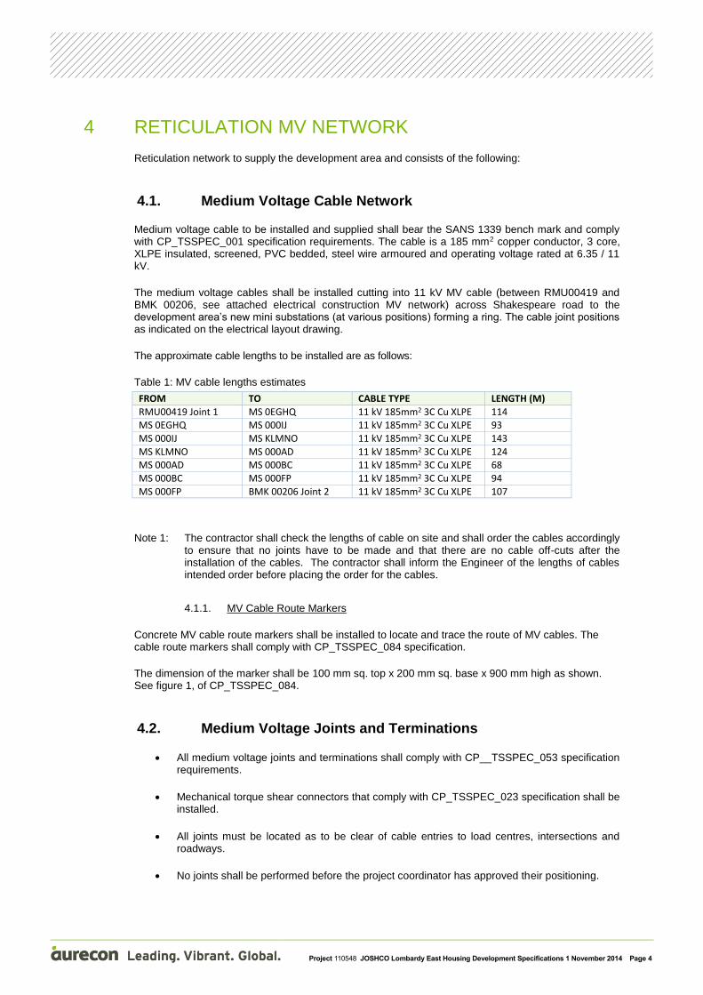
The approximate cable lengths to be installed are as follows:
Table 1: MV cable lengths estimates
FROM TO CABLE TYPE LENGTH (M)
RMU00419 Joint 1 MS 0EGHQ 11 kV 185mm2 3C Cu XLPE 114 MS 0EGHQ MS 000IJ 11 kV 185mm2 3C Cu XLPE 93
MS 000IJ MS KLMNO 11 kV 185mm2 3C Cu XLPE 143
MS KLMNO MS 000AD 11 kV 185mm2 3C Cu XLPE 124 MS 000AD MS 000BC 11 kV 185mm2 3C Cu XLPE 68
MS 000BC MS 000FP 11 kV 185mm2 3C Cu XLPE 94
MS 000FP BMK 00206 Joint 2 11 kV 185mm2 3C Cu XLPE 107
Note 1: The contractor shall check the lengths of cable on site and shall order the cables accordingly to ensure that no joints have to be made and that there are no cable off-cuts after the installation of the cables. The contractor shall inform the Engineer of the lengths of cables intended order before placing the order for the cables.
4.1.1. MV Cable Route Markers
Concrete MV cable route markers shall be installed to locate and trace the route of MV cables. The cable route markers shall comply with CP_TSSPEC_084 specification.
The dimension of the marker shall be 100 mm sq. top x 200 mm sq. base x 900 mm high as shown. See figure 1, of CP_TSSPEC_084.
4.2. Medium Voltage Joints and Terminations
All medium voltage joints and terminations shall comply with CP__TSSPEC_053 specification requirements.
Mechanical torque shear connectors that comply with CP_TSSPEC_023 specification shall be installed.
All joints must be located as to be clear of cable entries to load centres, intersections and roadways.
No joints shall be performed before the project coordinator has approved their positioning.
Project 110548 JOSHCO Lombardy East Housing Development Specifications 1 November 2014 Page 5
All MV joints and terminations shall be marked with the relevant contractor & artisan information on the ID tag provided in accordance with CP_TSSPEC_053.
Only artisans trained and accredited in accordance to City Power requirements shall be allowed to carry out MV cable jointing and terminations.
MV terminations onto SF6 switchgear shall be carried out in accordance with CP_TSPROC_028.
On type ‘C” bushings, only fully insulated separable connectors shall be used. No putty and type or empire tape shall be used due to the design of the bushing.
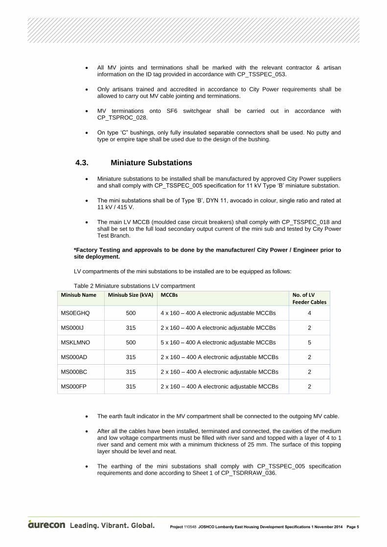
4.3. Miniature Substations
Miniature substations to be installed shall be manufactured by approved City Power suppliers and shall comply with CP_TSSPEC_005 specification for 11 kV Type ‘B’ miniature substation.
The mini substations shall be of Type ‘B’, DYN 11, avocado in colour, single ratio and rated at 11 kV / 415 V.
The main LV MCCB (moulded case circuit breakers) shall comply with CP_TSSPEC_018 and shall be set to the full load secondary output current of the mini sub and tested by City Power Test Branch.
*Factory Testing and approvals to be done by the manufacturer/ City Power / Engineer prior to site deployment.
LV compartments of the mini substations to be installed are to be equipped as follows:
Table 2 Miniature substations LV compartment
Minisub Name Minisub Size (kVA) MCCBs No. of LV Feeder Cables
MS0EGHQ 500 4 x 160 – 400 A electronic adjustable MCCBs 4
MS000IJ 315 2 x 160 – 400 A electronic adjustable MCCBs 2
MSKLMNO 500 5 x 160 – 400 A electronic adjustable MCCBs 5
MS000AD 315 2 x 160 – 400 A electronic adjustable MCCBs 2
MS000BC 315 2 x 160 – 400 A electronic adjustable MCCBs 2
MS000FP 315 2 x 160 – 400 A electronic adjustable MCCBs 2
The earth fault indicator in the MV compartment shall be connected to the outgoing MV cable.
After all the cables have been installed, terminated and connected, the cavities of the medium and low voltage compartments must be filled with river sand and topped with a layer of 4 to 1 river sand and cement mix with a minimum thickness of 25 mm. The surface of this topping layer should be level and neat.
The earthing of the mini substations shall comply with CP_TSSPEC_005 specification requirements and done according to Sheet 1 of CP_TSDRRAW_036.
Project 110548 JOSHCO Lombardy East Housing Development Specifications 1 November 2014 Page 6
4.4. Miniature Substation Plinth
All mini substations shall be installed on reinforced concrete Type ‘B’, Pre-cast plinths complying with CP_TSSPEC_027 specification for concrete plinths.
The top of the concrete plinth shall be level and shall protrude 150 mm above the final ground level irrespective of the fall of the ground.
Test requirements of SANS 5863 shall be completed.
5 LOW VOLTAGE NETWORK
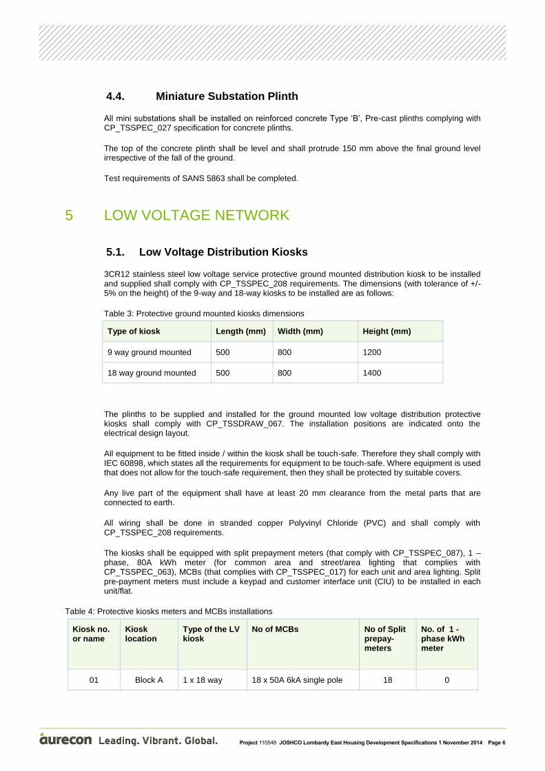
5.1. Low Voltage Distribution Kiosks
3CR12 stainless steel low voltage service protective ground mounted distribution kiosk to be installed and supplied shall comply with CP_TSSPEC_208 requirements. The dimensions (with tolerance of +/- 5% on the height) of the 9-way and 18-way kiosks to be installed are as follows:
Table 3: Protective ground mounted kiosks dimensions
Type of kiosk Length (mm) Width (mm) Height (mm)
9 way ground mounted 500 800 1200
18 way ground mounted 500 800 1400
The plinths to be supplied and installed for the ground mounted low voltage distribution protective kiosks shall comply with CP_TSSDRAW_067. The installation positions are indicated onto the electrical design layout.
All equipment to be fitted inside / within the kiosk shall be touch-safe. Therefore they shall comply with IEC 60898, which states all the requirements for equipment to be touch-safe. Where equipment is used that does not allow for the touch-safe requirement, then they shall be protected by suitable covers.
Any live part of the equipment shall have at least 20 mm clearance from the metal parts that are connected to earth.
All wiring shall be done in stranded copper Polyvinyl Chloride (PVC) and shall comply with CP_TSSPEC_208 requirements.
The kiosks shall be equipped with split prepayment meters (that comply with CP_TSSPEC_087), 1 – phase, 80A kWh meter (for common area and street/area lighting that complies with CP_TSSPEC_063), MCBs (that complies with CP_TSSPEC_017) for each unit and area lighting. Split pre-payment meters must include a keypad and customer interface unit (CIU) to be installed in each unit/flat.
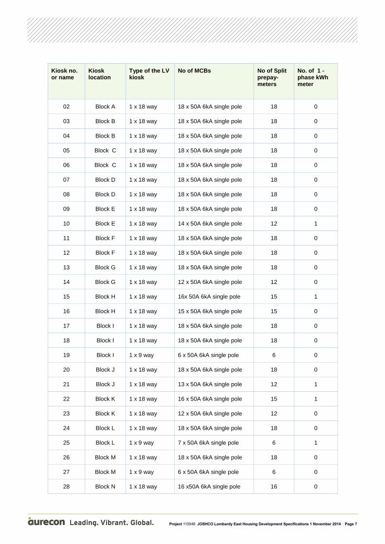
Table 4: Protective kiosks meters and MCBs installations
Kiosk no. or name
Kiosk location
Type of the LV kiosk
No of MCBs No of Split prepay-meters
No. of 1 -phase kWh meter
01 Block A 1 x 18 way 18 x 50A 6kA single pole 18 0
Project 110548 JOSHCO Lombardy East Housing Development Specifications 1 November 2014 Page 7
Kiosk no. or name
Kiosk location
Type of the LV kiosk
No of MCBs No of Split prepay-meters
No. of 1 -phase kWh meter
02 Block A 1 x 18 way 18 x 50A 6kA single pole 18 0
03 Block B 1 x 18 way 18 x 50A 6kA single pole 18 0
04 Block B 1 x 18 way 18 x 50A 6kA single pole 18 0
05 Block C 1 x 18 way 18 x 50A 6kA single pole 18 0
06 Block C 1 x 18 way 18 x 50A 6kA single pole 18 0
07 Block D 1 x 18 way 18 x 50A 6kA single pole 18 0
08 Block D 1 x 18 way 18 x 50A 6kA single pole 18 0
09 Block E 1 x 18 way 18 x 50A 6kA single pole 18 0
10 Block E 1 x 18 way 14 x 50A 6kA single pole 12 1
11 Block F 1 x 18 way 18 x 50A 6kA single pole 18 0
12 Block F 1 x 18 way 18 x 50A 6kA single pole 18 0
13 Block G 1 x 18 way 18 x 50A 6kA single pole 18 0
14 Block G 1 x 18 way 12 x 50A 6kA single pole 12 0
15 Block H 1 x 18 way 16x 50A 6kA single pole 15 1
16 Block H 1 x 18 way 15 x 50A 6kA single pole 15 0
17 Block I 1 x 18 way 18 x 50A 6kA single pole 18 0
18 Block I 1 x 18 way 18 x 50A 6kA single pole 18 0
19 Block I 1 x 9 way 6 x 50A 6kA single pole 6 0
20 Block J 1 x 18 way 18 x 50A 6kA single pole 18 0
21 Block J 1 x 18 way 13 x 50A 6kA single pole 12 1
22 Block K 1 x 18 way 16 x 50A 6kA single pole 15 1
23 Block K 1 x 18 way 12 x 50A 6kA single pole 12 0
24 Block L 1 x 18 way 18 x 50A 6kA single pole 18 0
25 Block L 1 x 9 way 7 x 50A 6kA single pole 6 1
26 Block M 1 x 18 way 18 x 50A 6kA single pole 18 0
27 Block M 1 x 9 way 6 x 50A 6kA single pole 6 0
28 Block N 1 x 18 way 16 x50A 6kA single pole 16 0

Project 110548 JOSHCO Lombardy East Housing Development Specifications 1 November 2014 Page 8
Kiosk no. or name
Kiosk location
Type of the LV kiosk
No of MCBs No of Split prepay-meters
No. of 1 -phase kWh meter
29 Block O 1 x 18 way 17 x 50A 6kA single pole 16 1
30 Block P 1 x 18 way 18 x 50A 6kA single pole 18 0
31 Block P 1 x 18 way 18 x 50A 6kA single pole 18 0
32 Block P 1 x 9 way 2 x 50A 6kA single pole 0 1
33 Block Q 1 x 18 way 18 x 50A 6kA single pole 18 0
34 Block Q 1 x 18 way 12 x 50A 6kA single pole 12 0
35 MS 000AD 1 x 9 way 4 x 50A 6kA single pole 0 1
5.2. Area Lighting Low Voltage Kiosks
Area/street lighting kiosks to be supplied and installed are required to be supplied fully assembled and ready to use.
The kiosk shall be able to house several MCBs, a contactor and a fuse of suitable rating to be mounted on to DIN rails. The coil of the contactor shall be connected to a PECU NEMA base mounted (with its gasket) on the top of the kiosk. The contactor shall have an AC3 rating of 40A per pole that fully comply with the requirements of SANS IEC 60947-4 and shall bear the applicable SANS or IEC mark. The photocell shall be in accordance with SABS 1777 (rated to operate at 230 V ± 10% 50 Hz).
The kiosk shall be a two-door kiosk, 3CR12-2.0mm with hinge lockable doors in the front and rear. The enclosure shall have a DIN rail fixed in the upper section and a section of DIN rail mounted in the lower section. The front of the kiosk must accommodate all outgoing feeder, control circuit and bypass function circuit breakers. The rear of the kiosk must accommodate cable to busbar terminations. The busbar shall be rated at a minimum of 100A. The kiosk shall be protected against moisture ingress and have a minimum IP rating of 53.
The entire installation shall be protected by one 100 A HRC fuse. The outgoing circuits (50 A), control circuit (5 A) and bypass function (100 A) MCBs must be rated at 6kA and, shall be touch safe and DIN rail mounted. Provision shall be made for future mounting of one or two extra outgoing (load) MCBs.
Table 5: Street lighting kiosks
Kiosk no. or name
Kiosk location
No. of outgoing street lighting circuits
No. of outgoing feeders to supply common areas
No. of 3-phase contactor
A1 Block L 2 3 1
A2 Block J 2 2 1
A3 Block H 2 2 1
Project 110548 JOSHCO Lombardy East Housing Development Specifications 1 November 2014 Page 9
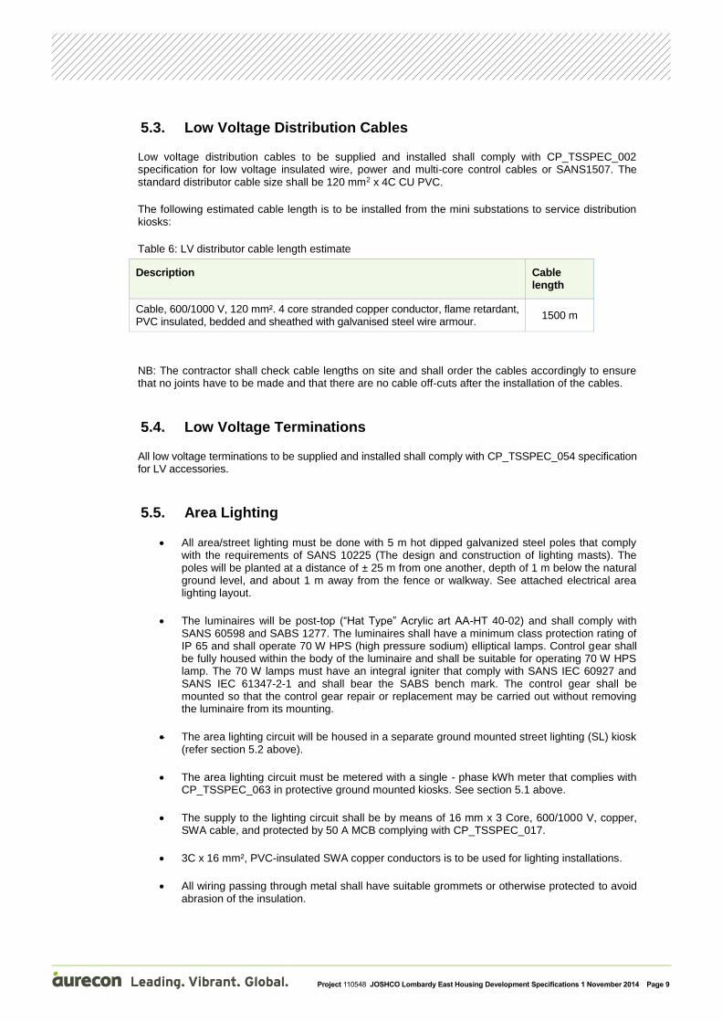
5.3. Low Voltage Distribution Cables
Low voltage distribution cables to be supplied and installed shall comply with CP_TSSPEC_002 specification for low voltage insulated wire, power and multi-core control cables or SANS1507. The standard distributor cable size shall be 120 mm2 x 4C CU PVC.
The following estimated cable length is to be installed from the mini substations to service distribution kiosks:
Table 6: LV distributor cable length estimate
Description Cable length
Cable, 600/1000 V, 120 mm². 4 core stranded copper conductor, flame retardant, PVC insulated, bedded and sheathed with galvanised steel wire armour.
1500 m
NB: The contractor shall check cable lengths on site and shall order the cables accordingly to ensure that no joints have to be made and that there are no cable off-cuts after the installation of the cables.
5.4. Low Voltage Terminations
All low voltage terminations to be supplied and installed shall comply with CP_TSSPEC_054 specification for LV accessories.
5.5. Area Lighting
All area/street lighting must be done with 5 m hot dipped galvanized steel poles that comply with the requirements of SANS 10225 (The design and construction of lighting masts). The poles will be planted at a distance of ± 25 m from one another, depth of 1 m below the natural ground level, and about 1 m away from the fence or walkway. See attached electrical area lighting layout.
The luminaires will be post-top (“Hat Type” Acrylic art AA-HT 40-02) and shall comply with SANS 60598 and SABS 1277. The luminaires shall have a minimum class protection rating of IP 65 and shall operate 70 W HPS (high pressure sodium) elliptical lamps. Control gear shall be fully housed within the body of the luminaire and shall be suitable for operating 70 W HPS lamp. The 70 W lamps must have an integral igniter that comply with SANS IEC 60927 and SANS IEC 61347-2-1 and shall bear the SABS bench mark. The control gear shall be mounted so that the control gear repair or replacement may be carried out without removing the luminaire from its mounting.
The area lighting circuit will be housed in a separate ground mounted street lighting (SL) kiosk (refer section 5.2 above).
The area lighting circuit must be metered with a single - phase kWh meter that complies with CP_TSSPEC_063 in protective ground mounted kiosks. See section 5.1 above.
The supply to the lighting circuit shall be by means of 16 mm x 3 Core, 600/1000 V, copper, SWA cable, and protected by 50 A MCB complying with CP_TSSPEC_017.
3C x 16 mm², PVC-insulated SWA copper conductors is to be used for lighting installations.
All wiring passing through metal shall have suitable grommets or otherwise protected to avoid abrasion of the insulation.

Project 110548 JOSHCO Lombardy East Housing Development Specifications 1 November 2014 Page 10
Luminaires shall be earthed in accordance with SANS 60598-2-3. The body of the lamp holder shall be connected to the supply earth. The neutral and earth shall be interconnected in the luminaire.
A 5A (6kA) MCB shall be used for each luminaire connection at the base of the pole.
All the internal wiring of the luminaires shall comply with SANS 60598-2-3. All internal wiring must be Teflon coated and sleeved where required to prevent damage by abrasions.
Wiring between the luminaire and the cable connection at the bottom of the pole shall consist of two 2.5 mm2 PVC-insulated copper conductors and 2.5 mm2 bare copper earth wire.
6 CABLE TRENCHING AND INSTALLATIONS
The Contractor shall ensure that the cable trenches are excavated to the specified depth and that the cables are laid with the specified distances between the cables (See table below). Where the cables cross other services, the clearances as specified in the relevant section shall be maintained. Where the cables cross other services a concrete slab shall be installed above the cable at the point of crossing of the two services.
The following are the cable trench widths and depths and spacing between cables as specified in CP_TSSTAN_009.
Table 7: Cable trench depths, width and spacing
Cable Type Depth below final
ground level
Typical Trench
Dimensions
Min. Cable
Spacing
MV cables 1000 mm 450 mm 150
LV cables 600 mm 450 mm 0
SL cables 600 mm 450 mm 0
NB: Where larger of no’s of cables are to be installed the trench width shall be determined by no. of cables and spacing between them.
Where site constraints dictate it is necessary to install services within common trench, it is imperative that the minimum horizontal separation of 600 mm is maintained between City Power services and any other services. All City Power services shall be in such circumstances be protected by means of “boxing” with concrete cable slabs and any other services.
It is not permissible to lay other services above or below City power services.
The length of the cable that must be excavated at the time must not exceed 300 m, following which a length of cable must be laid, inspected and the cable trench backfilled before further excavations are carried out (i.e. standardise on the drum length).
Rocks removed from excavations shall not be used for backfilling.
Cables shall be laid in accordance with manufacturer’s recommendations and SANS 10198.
Cables shall only be laid in trenches having smooth flat bottom surfaces. Where the surfaces are irregular they shall first be smoothed off before installing the cables.

Project 110548 JOSHCO Lombardy East Housing Development Specifications 1 November 2014 Page 11
Where cables are installed in trenches cut in rock, a 75 mm layer of fine sifted earth must be placed on the bottom of the trench to serve as bedding for the cables. Final depth of the cable shall still be in accordance with the table below.
All cables shall be installed in straight lines as far as possible and excessive distortion and weaving in the cable length is not accepted.
After the cable has been installed it must be covered with a 200 mm layer of well-compacted earth. In the case of a trench cut into rock, this layer is to consist of fine sifted earth.
The spoil shall be removed and adequate bedding soil obtained for backfilling.
Cables, which have been laid, must be energised as soon as possible to limit the possibility of theft of cable.
An embossed, yellow-coloured plastic maker tape 150 mm wide by 0.1 mm thick and complying with CP_TSSPEC_078 shall be laid in a continuous strip above all cable at a depth of 150 mm.
The minimum requirements of SANS 10198 shall be complied with, when back filling cable trenches. Also, adhere to Johannesburg Roads Agency’s Wayleave code of practice.
City Power danger tape to be installed 300mm below natural ground level in cable trench.
6.1. Cable Sleeve Pipes
At road crossings, both MV and LV cables shall be laid at a depth of 1 m below the road surface. These cables shall be laid in black corrugated flexible PVC sleeves, 110 mm in outer diameter and must be supplied with pilot strings. The protective sleeves shall comply with CP_TSSPEC_134 specification for flexible protective PVC sleeves. The low voltage cables shall be ramped up and down at reach side of these crossings points accordingly.
Sleeves must protrude by a minimum of 1 m beyond the kerbstone.
All sleeves must have a draw wire and be suitable sealed at both ends. As a standard each crossing shall consist of 3 sleeves in trefoil configuration.
The location of the sleeves shall be marked with an ‘E’ embossed into the kerb at both ends.
The protective sleeves are to be installed by way of directional operated trenchless technology. Other installation methods are to be approved by the engineer or by City Power.
Sleeves positions are indicated onto the electrical construction layout.
6.2. Concrete Slabs
Due to the fact that the contracts for the electrical and civil contracts will be running concurrently it may occur that the electrical services will be installed before the civil services in certain areas. In this event it will be the responsibility of the electrical contractor to ascertain where the civil services will cross the electrical cables and to install concrete slabs as specified over the electrical cables. If necessary the cables shall be installed deeper at the point of crossing to maintain the specified minimum clearances between the services.
Project 110548 JOSHCO Lombardy East Housing Development Specifications 1 November 2014 Page 12
7 EARTHING
A TN-C-S earthling system in accordance with SANS 10292 (earthing of low-voltage distribution systems) shall be installed. The neutral and earth at the residential consumers shall be terminated in the relevant SDB (service distribution box) as per CP_TSPROC_014.
8 MAINTENANCE AND OPERATING MANUALS
Before handing over the installation, the Contractor shall submit operating manuals which must include the following:
Recommendations for weekly, monthly and yearly maintenance.
Brochures providing the necessary technical information about luminaires, miniature substations, etc.
A complete equipment list with manufacturer, model, type and supplier’s contact details.
9 MARKING AND LABELLING
All equipment shall be labelled as indicated on the electrical reticulation drawings.
The marking and labels of the mini substation shall comply with CP_TSSPEC_005 specification.
Notices, danger and warning signs to be installed on the distribution network shall comply with CP_TSSPEC_078.
All service connection circuit breakers shall be identified with the intended unit/flat number.
10 COMMISSIONING
Prior to termination or jointing of MV cables a moisture test shall be carried out in accordance with CP_TSPROC_003.
Prior to executing any jointing or terminating of cables, a 48 hours’ notice must be given to the project co-ordinator so that arrangements may be made for inspections to be carried out during and on completion of these operations. This is also applicable to isolations required in order to energise the new network.
Under no circumstances may the cable trenches and joint holes be backfilled until clearance has been given by the project coordinator.
11 TESTING
All installed equipment shall be commissioned and tested as per the manufacturer’s recommendations. The results of all tests must be recorded and submitted to the clerk of works or project coordinator for approval.
Routine factory tests reports shall accompany all equipment supplied and shall be given to the project coordinator or clerk of works, prior to the equipment being installed and commissioned.

Project 110548 JOSHCO Lombardy East Housing Development Specifications 1 November 2014 Page 13
Prior to handover, on site final test reports as listed in CP_TSCHECK_037, CP_TSCHECK_039, and CP_TSCHECK_043 for all equipment shall be given to the relevant
City Power official.
Contractor to provide COCs and pressure test certificates to engineer prior to energizing of equipment.
12 DRAWINGS
Drawings which depict services, e.g. water pipes, sewerage, telecommunication cables, etc will be obtained from the authority responsible for the service by the contractor. The correctness and accuracy of these drawings will however not be guaranteed and will be the contractor or consultants responsibility to establish the exact position of these services prior to commencement of excavations.
A complete set of updated drawings for the installation shall be available on site at all times.
Before final acceptance of the completed installation, the contractor shall furnish all the necessary “as-built” information, marked up in red pen on paper prints of the construction drawings. The information shall include every detail required to establish the exact position of all cables, cable joints and other equipment, which have been installed as part of this contract. Fixed references such as stand pegs or boundaries shall be used to locate the above items positively.
13 CLEANING OF SITE
After completion of construction activities, the contractor shall remove all his equipment and site facilities from the site and leave the site in a tidy condition. The cost thereof must be included for in the P & G’s.