Embed Size (px)
Citation preview

Design of Modular Fault Tolerant Manipulators
Christiaan J. J. Paredis, Carnegie Mellon University, Pittsburgh, PA, USA
Pradeep K. Khosla, Carnegie Mellon University, Pittsburgh, PA, USA
In this paper, we deal with two important issues in re-
lation to modular recon�gurable manipulators, namely,
the determination of the modular assembly con�gura-
tion optimally suited to perform a speci�c task and
the synthesis of fault tolerant systems. We present a
numerical approach yielding an assembly con�guration
that satis�es four kinematic task requirements: reach-
ability, joint limits, obstacle avoidance and measure of
isotropy. Further, because critical missions may in-
volve high costs if the mission were to fail due to a fail-
ure in the manipulator system, we address the prop-
erty of fault tolerance in more detail. We prove the
existence of fault tolerant manipulators and develop an
analysis tool to determine the fault tolerant work space.
We also derive design templates for spatial fault toler-
ant manipulators. For general purpose manipulators
two redundant degrees-of-freedom are needed for every
order of fault tolerance. However, we show that only
one degree of redundancy is su�cient for task speci�c
fault tolerance.
1 Introduction
Conventional (serial or parallel link) manipulators areoften considered to be general-purpose and exible sys-tems. Unfortunately, these systems are not generalpurpose. In order to understand this, consider a com-puter which is a general purpose computing engine if itcan compute a computable function. Following a sim-ilar logic, a manipulator will be general purpose if itcould do a `doable' task. In de�ning a general purposemanipulator, one has, of course, to de�ne a `doable'task �rst. For the time being, let us avoid this openissue and consider two tasks that two di�erent manip-ulators can perform, but that cannot be performed byeither manipulator separately. If this is the case, thenone may conclude that none of the above two manip-ulators are general purpose. So if one has to de�ne a
general purpose manipulator, then one has �rst to de-�ne a criterion for `doable' tasks (like `doability'). Sucha de�nition may lead to the development of models of`doability' (like computability) and maybe to Turing-like machine models of manipulators. While such a de-velopment would certainly do a lot for advancing thestate-of-the-art in manipulators, it is not our intentionto address this general problem.
In order to make the problem tractable, let us de-�ne a set of tasks that we would like to perform with amanipulator. Let us also de�ne a set of basic modules(consisting of joints and links) that we may combine tocreate various manipulators. Finally, let us assume theexistence of a methodology that will accept a task (inthe form of a program or as a set of requirements) asinput and �nd a manipulator that can be created fromthe given set of modules to perform the task. Thisscenario is described in Fig. 1, and it allows us to putforth one possible de�nition of a general-purpose ma-nipulator.
General-purpose Manipulator: If for every task inthe set of tasks, it is possible to �nd a manipulatorthat can be created from the given set of modules to dothe task, then we de�ne the system of modules (or thesystem of all possible manipulators) as general purposewith respect to the set of tasks. We will call such asystem a Recon�gurable Modular Manipulator System(RMMS).
Note that the above de�nition does not require us tode�ne a set of all possible `doable' tasks nor does it re-quire us to de�ne the criteria for determining `doability'even though that is the ultimate goal of our research.
Our past work has addressed the development of themodules and the technology for the RMMS [21]. TheRMMS has many potential applications in both haz-ardous and industrial environments. It puts forth theidea of designing a speci�c manipulator for a task and

C. Paredis and P. Khosla
Task Program
Manipulators Modules
Abstract Task Requirements
input
output
Reconfigurable Modular Manipulator Systems
Reconfigurable Modular Manipulator System?Is Task Program executable by
− VAL II
− C code
− ....
− D−H parameters− Material specifications− Motor speicifications
− Module specifications
− positions/orientations− force application− accuracy− dexterity− obstacles− ....
Figure 1: De�nition of a general purpose manipulator.
also the notion of the user writing device (or manip-ulator) independent code. The RMMS raises severaltheoretical issues and it is our aim to address one ofthese in this paper. Speci�cally, we describe a designmethodology that accepts a task speci�cation as itsinput, determines a kinematic con�guration of the de-sired manipulator and selects the modules to createthis manipulator.
In order to support the current practice of pickingthe best con�guration amongst available robots, sev-eral expert systems have been built to aid the user orthe applications development engineer [15]. A straight-forward extension of this selection process has been theinclusion of the design of new manipulators, optimallysuited for a speci�c application [1, 16]. A totally di�er-ent approach to the robot design problem �nds its rootsin simulation. A variety of commercial robot simula-tion packages are currently available [5, 22], providingdesigners with convenient tools to quickly check theimplications of di�erent design decisions. In general,however, these simulation packages still require a hu-man to make the design decisions. Finally, a third wayof dealing with the problem of robot design, has grownout of the �eld of mechanism design [13, 19]. Unlikethe rule based expert systems, these programs are al-
gorithmic in nature. Commonly, the design process issubdivided in two stages: form synthesis and dimen-sional synthesis. The �rst stage is usually performedby searching over the set of feasible mechanism types,while the second stage consists of optimizing the set ofdimensional parameters.
The approach we propose in this paper di�ers fromthe methods listed above, because we are speci�callyinterested in modular manipulators. The interest inmodular manipulators has grown steadily over the lastdecade [6, 24], and several related research issues havebeen addressed [2, 3, 7, 10, 14, 18]. However, theproblem of determining the modular con�guration op-timally suited for one speci�c task, has never been ad-dressed before to the best of our knowledge. In thispaper, we investigate modular design from kinematictask requirements. These requirements a�ect only thekinematic structure of the manipulator, while dynamicrequirements a�ect both its kinematic and dynamicstructure. Examples of kinematic requirements arework space volume, maximum reach, and maximumpositional error. Examples of dynamic requirementsare maximum pay-load, maximum joint velocities, andmaximum joint accelerations. Just as task require-ments can be classi�ed as kinematic or dynamic re-quirements, the design procedure can also be split intotwo parts: kinematic design and dynamic design [10].Kinematic design determines the kinematic structureof the manipulator, while dynamic design determinesthe dynamic con�guration. However, the dynamic de-sign may require a change in kinematic structure, andthus a few iterations may be necessary to �nd a ma-nipulator that satis�es both kinematic and dynamicrequirements.
In the �rst part of this paper, we only consider reach-ability, joint limit, obstacle avoidance, and measure ofisotropy requirements. A numerical procedure is pro-posed which determines a modular assembly con�gu-ration that meets all the requirements. In the secondpart, we focus our attention on one additional require-ment, namely, fault tolerance. Recently, fault tolerant(or failure tolerant) robotics has been the subject ofseveral publications [11, 23], in which di�erent aspectsof the problem are addressed. Visinsky et al. [23] pro-pose a framework to include failure detection in faulttolerant robot systems. Lewis and Maciejewski [11],on the other hand, discuss the importance of the con-troller and the redundancy resolution. In this paper,

Design of Modular Fault Tolerant Manipulators
we focus our attention on the design of fault tolerantmanipulators. We de�ne fault tolerance as the abil-ity to continue the performance of a task even afterimmobilization of a joint due to failure. Several prop-erties of fault tolerant manipulators are discussed andare illustrated with examples.
2 Kinematic Design: Preliminary Re-
sults
2.1 Problem Statement
The problem solved in this section is the determinationof a modular assembly con�guration, that satis�es allthe kinematic task requirements. These requirementsare that the manipulator must be able to reach a spec-i�ed set of positions/orientations, pj, (reachability re-quirement), without violating the motion constraints ofthe joint modules (joint limit requirement), and with-out colliding with any parallelepiped-shaped obstaclesin the work space (obstacle avoidance requirement).Moreover, at the positions/orientations, pj, the mea-sure of isotropy, must be larger than a user speci�edminimum (measure of isotropy requirement).
In Section 2.2 and 2.3, we develop a numerical pro-cedure to solve this design problem. To facilitate theimplementation of our approach, we consider six typesof modules, as shown in Fig. 2. The choice of these spe-ci�c modules guarantees a simple conversion from themodule dimensions and orientations into the Denavit-Hartenberg (D-H) parameters of the resulting manipu-lator (a set of 3 D-H parameters per degree-of-freedom,determines unambiguously the kinematic structure ofany serial link manipulator). It has been shown by Kel-mar and Khosla [7] that this conversion can be achievedfor modules of arbitrary geometry. The actual numberof di�erent modules considered for the design can befar larger than six, due to variations in the parame-terized dimensions, and our design method is generalenough to allow for this.
We also require that the robot base be �xed andknown, that the �rst joint module be of type 0 or 1 (i.e.the �rst joint axis is vertical), and that the last mod-ule be a wrist with three axes intersecting at a point.These restrictions result from our implementation ofthe inverse kinematics and can be relaxed by using it-erative solutions to the inverse kinematics problem, asproposed in [2]. Also, the requirement that the robot
Joint 2:
Joint 1:
L2
L1
d
d
L2
d
Joint 0:
d
L1
Joint 3:
Links:
LL2
L1
Straight link totally determined by its length. Three roll wrist.
Four types of joints
Figure 2: The types of manipulator modules that are con-
sidered in the design procedure.
base be �xed and known, can be relaxed as was shownby Kim [8], who addressed the problem of kinematicsynthesis and base position synthesis simultaneously.
Finally, we would like to point out that this designproblem can possibly have more than one solution.Consider the design of a 2-DOF planar manipulator,with link lengths L1 and L2, satisfying the task require-ment that the manipulator should be able to reach apoint located behind an obstacle without violating thejoint limits, as is illustrated in Fig. 3. The region of the(L1;L2)-plane containing the solutions is bounded bythe curves labeled c, d and e. All the manipulators in-side this region satisfy all the design requirements and,therefore, are all equally good with respect to theserequirements.
2.2 Solution Approach
In this section, we evaluate di�erent approaches tothe problem of determining the modular con�guration,given some kinematic task speci�cations. The prob-lem can be interpreted as a mapping from task speci-�cations into constraints in the modular con�gurationspace, as is shown in Fig. 1. This mapping is nontrivialdue to the highly nonlinear character of the kinematic

Figure 3: A two-DOF planar design example with solution.
relations and due to the complexity of the task speci-�cations. Krishnan [10], therefore, suggested to solvethe inverse problem �rst, namely, to analyze which taskrequirements are satis�ed by a given modular con�g-uration. This information is stored in lookup tables,which can then be used in a search procedure. Oneobvious disadvantage to this approach is the combina-torial explosion in the number of di�erent con�gura-tions. Let the number of di�erent modules availablebe N , and let R be the number of relative orientationsin which one module can be mounted on the previousmodule. The total number of con�gurations that canbe obtained from this set of modules is:
Num =NXi=1
R(i�1) N !
(N � i)!(1)
This approach would therefore require a very largeamount of memory storage for the lookup tables. Also,adding a new module requires that all the lookup tablesbe updated.
A di�erent approach is to �rst design a manipulatorde�ned by a set of continuously varying D-H parame-ters, as proposed in [17], and then transform this designinto a modular con�guration. The main problem hereis the discretization of the continuous solution. As isknown from integer programming, simply taking thediscrete con�guration nearest to the continuous solu-tion might result in an infeasible solution. Therefore,we suggest working directly in the modular con�gu-ration space. Of course, an exhaustive search in thisspace su�ers from combinatorial explosion in much thesame way the look up table approach does. However,the e�ciency of the search procedure can be improveddrastically by `guiding' the search to the most promis-ing regions of the search space. Instead of answeringthe question whether a certain modular design meetsall the task requirements with a simple `yes' or `no',we estimate the `goodness' or `badness' of the design,i.e., \How far are we away from a solution?" Guid-ing the search then means focusing the search e�orton directions of decreasing `badness'. This approachis usually referred to as a heuristic search technique[20], because in general, it is impossible to computethe `badness', or the distance to the nearest solution,exactly. The heuristic function only estimates this dis-tance so that it is possible that, locally, the heuristicdecreases even though the actual distance to a solutionincreases. This corresponds to a local minimum in op-timization terminology. To overcome this inadequacy,we have to employ a search method, such as simulatedannealing, that allows for local hill climbing.
Simulated annealing was �rst proposed by Kirk-patrick [9] as a combinatorial optimization algorithm.The method is a random iterative improvement algo-rithm with the modi�cation that, under certain condi-tions, an increase in the heuristic function is accepted(In order to be compatible with the standard termi-nology in discussions of simulated annealing, we usethe term objective function instead of heuristic func-tion, henceforth). A new trial con�guration is gener-
Design of Modular Fault Tolerant Manipulators
ated randomly in the neighborhood of the current con-�guration. The condition for acceptance of this trialcon�guration is:
��Fobj � 0 ) accept
exp(��Fobj=T ) > random[0;1) ) accept(2)
which depends on a control variable, T , the tempera-ture. The algorithm is started at a high temperaturefor which most new con�gurations are accepted. Af-ter each iteration the temperature is decreased untilno new acceptable con�guration can be found. Thesearch is then frozen. We adapted this basic algorithmto include the special properties of our objective func-tion. In particular, the algorithm is stopped when anew trial con�guration has an objective function valueequal to zero, even if the search is not yet frozen. Weknow that a con�guration with a `badness' of zero sat-is�es all the design requirements.
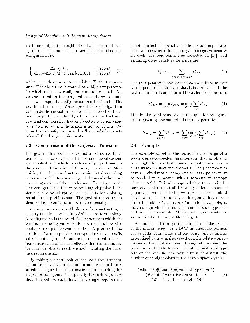
2.3 Computation of the Objective Function
The goal in this section is to �nd an objective func-tion which is zero when all the design speci�cationsare satis�ed and which is otherwise proportional tothe amount of violation of these speci�cations. Min-imizing the objective function by simulated annealingcorresponds then to a search, guided towards the mostpromising regions of the search space. For a given mod-ular con�guration, the corresponding objective func-tion can also be interpreted as a penalty for violatingcertain task speci�cations. The goal of the search isthen to �nd a con�guration with zero penalty.
We now propose a methodology for constructing apenalty function. Let us �rst de�ne some terminology.A con�guration is the set of D-H parameters which de-termines unambiguously the kinematic structure of amodular manipulator con�guration. A posture is theposition of a manipulator corresponding to a speci�cset of joint angles. A task point is a speci�ed posi-tion/orientation of the end e�ector that the manipula-tor must be able to reach without violating the othertask requirements.
By taking a closer look at the task requirements,one notices that all the requirements are de�ned for aspeci�c con�guration in a speci�c posture reaching fora speci�c task point. The penalty for such a postureshould be de�ned such that, if any single requirement
is not satis�ed, the penalty for the posture is positive.This can be achieved by de�ning a nonnegative penaltyfor each task requirement, as described in [17], andsumming these penalties for a posture:
Ppost =X
requirements
Preq (3)
The task penalty is now de�ned as the minimum overall the posture penalties, so that it is zero when all thetask requirements are satis�ed for at least one posture:
Ptask = minpost
Ppost = minpost
(Xreq
Preq) (4)
Finally, the total penalty of a manipulator con�gura-tion is given by the sum of all the task penalties:
Pconf =Xtasks
Ptask =Xtasks
(minpost
(Xreq
Preq)) (5)
2.4 Example
The example solved in this section is the design of aseven degree-of-freedom manipulator that is able toreach eight di�erent task points, located in an environ-ment which includes �ve obstacles. The joint moduleshave a limited motion range and the task points mustbe reached in a posture with a measure of isotropyof at least 0.6. It is also required that the manipula-tor consists of a subset of the twenty di�erent modules(4 joints, 1 wrist, 16 links: we also consider a link oflength zero). It is assumed, at this point, that an un-limited number of each type of module is available, sothat a design which includes the same module type sev-eral times is acceptable. All the task requirements aresummarized in the input �le in Fig. 4.
A quick calculation gives us an idea of the extentof the search space. A 7-DOF manipulator consistsof �ve links, four joints and one wrist, and is furtherdetermined by �ve angles, specifying the relative orien-tations of the joint modules. Taking into account therestrictions, that the �rst joint module must be of typezero or one and the last module must be a wrist, thenumber of con�gurations in the search space equals:
(#links)5(#joints)3(#joints of type 0 or 1)(#wrists)(#relative orientations)5
= 165 � 43 � 2 � 1 � 85 � 4:4� 1012(6)

C. Paredis and P. Khosla
7 # number of degrees of freedom3 # number of dimensions
8 # number of relative orientations16 # number of link modules#number |length#---------------------0 0.01 0.12 0.23 0.34 0.45 0.56 0.67 0.78 0.89 0.910 1.011 1.112 1.213 1.314 1.415 1.5
4 # number of joint modules#number|type |l1 |d |l2 |th_min |th_max#-----------------------------------------------------0 0 0.0 0.1 0.0 -150.0 150.01 1 0.1 0.1 0.0 -150.0 150.02 2 0.1 0.1 0.1 -150.0 150.03 3 0.1 0.1 0.1 -150.0 150.0
1 # number of wrist modules#number|l1 |l2 |min1 |max1 |min2 |max2 |min3 |max3#-------------------------------------------------------------------0 0.1 0.05 -100.0 100.0 -150.0 150.0 -266.0 266.0
0.6 # mi_min: min measure of isotropy.8 # num_points: number of points#xpos |ypos |zpos |Xrot |Yrot |Zrot#-----------------------------------------------------------0.5 0.5 1.0 0. 0. 90.0.5 0.0 0.5 0. 90. 0.0.5 0.0 1.5 0. -90. 0.0.5 -0.5 1.0 0. 0. -90.1.5 0.5 1.0 0. 0. 90.1.5 0.0 0.5 0. 90. 0.1.5 0.0 1.5 0. -90. 0.1.5 -0.5 1.0 0. 0. -90.
5 # num_obst: number of obstacles.#xpos |ypos |zpos |Xrot |Yrot |Zrot |xdim |ydim |zdim#-------------------------------------------------------------------2. -2. 0.425 0. 0. 0. 3.7 3.7 0.852. 2. 0.425 0. 0. 0. 3.7 3.7 0.852. -2. 1.425 0. 0. 0. 3.7 3.7 0.852. 2. 1.425 0. 0. 0. 3.7 3.7 0.85-1. 0. 1. 0. 0. 0. 1.9 4. 2.
Figure 4: The input �le of the 7-DOF example.
link# angle# joint#
1 10 4 12 14 4 33 3 3 04 12 6 35 14 0 |
Table 1: Module number of 7-DOF design.
Starting from a random initial guess, the simulatedannealing algorithm evaluated on the average onlyabout 2700 con�gurations before �nding a solution.One of these solutions is tabulated in Table 1 and Ta-ble 2. It is a SCARA-like manipulator with a nearlyspherical joint at the end of the second link. The o�set
DOF di ai �i
1 1.1 1.6 180o
2 0.1 0.0 90o
3 1.8 0.0 �90o4 0.1 0.0 90o
5 1.6 0.0 90o
6 0.0 0.0 �90o7 0.05 0.0 |
Table 2: D-H parameters of 7-DOF design.
Figure 5: The manipulator reaching point two while avoid-
ing all the obstacles.
along the �rst axis is 1 meter and the �rst twist an-gle is 180o, so that the �rst and second link move ina horizontal plane exactly between the four obstacles.Because of the spherical joint, link 3 can move eitherin a horizontal or a vertical plane, so that all the taskpoints can be reached without hitting any obstacles, asshown in Fig. 5.
3 General Purpose Fault Tolerant Ma-
nipulators
In the rest of this paper, we focus our attention on oneadditional task requirement, namely, fault tolerance.To set the stage for our development, we de�ne thefollowing properties of fault tolerant manipulators [2]:
� General Purpose Fault Tolerant Manipula-tor: An n-DOF manipulator that will still be ableto meet the task speci�cations, even if any one ormore of its joints fail and are frozen at any arbi-trary joint angles.

Design of Modular Fault Tolerant Manipulators
� k-Reduced Order Derivative (k-ROD):When k joints of an n-DOF manipulator fail, thee�ective number of joints is (n � k). The result-ing faulty manipulator is called a k-reduced orderderivative.
� Order of Fault Tolerance: An n-DOF manip-ulator is fault tolerant of the k-th order, if andonly if all k-reduced order derivatives can still per-form the speci�ed task. We call the manipulatork-fault-tolerant.
� Fault Tolerant Work Space (FTWS): Thefault tolerant work space of a k-fault tolerant ma-nipulator is the set of points reachable by all pos-sible k-reduced order derivatives.
These de�nitions di�er from the concept of fault tol-erance as proposed by Maciejewski [12]. Instead of at-tributing the property of fault tolerance to a manipu-
lator, he quanti�es a measure of fault tolerance for amanipulator posture and describes a technique to deter-mine the optimal fault tolerant posture, based on thesingular value decomposition of the Jacobian matrix.If a joint fails in this optimal posture, the resultingreduced order derivative will have maximum possibledexterity. However, a failure at a di�erent angle maymake the execution of the task impossible.
In the rest of this section, if no speci�c task is men-tioned, it is assumed that the task consists of reach-ing a nonzero volume of points in the task space, i.e.,an m-dimensional manifold in the m-dimensional taskspace. A manipulator that can only reach a manifoldof dimension lower than m in a fault tolerant way, isconsidered not to be fault tolerant.
4 Properties of General Purpose Fault
Tolerant Manipulators
4.1 Existence
A general purpose manipulator has six DOFs whichallow it to position its end e�ector in an arbitrary po-sition and orientation anywhere in its work space. Anobvious way to make this manipulator fault tolerant isto design every joint with a redundant actuator. If oneof the actuators of the resulting 2n-DOF fault tolerantmanipulator were to fail, the redundant actuator couldtake over and the manipulatorwould still be functional.
Similarly, a k-fault tolerant manipulator can be con-structed by duplicating every DOF k times, resultingin a (k + 1)n-DOF manipulator.
4.2 Boundary of the Fault Tolerant WorkSpace
In this section, we show that a boundary point of theFTWS is a critical value. Consider a k-fault tolerantplanar manipulator,M. A boundary point, pb, of theFTWS has to be an element of the boundary of thework space of at least one ROD,M�, obtained by freez-ing k joints of M. Indeed, if pb were an interior pointof the work spaces of all RODs, then it would by de�ni-tion be an interior point of the FTWS and not a bound-ary point. The Jacobian ofM�, JM� , can be obtainedfrom the Jacobian of M, JM , by deleting the columnscorresponding to the frozen DOFs. Because pb is aboundary point of the work space ofM�, the JacobianofM� at pb is singular. We prove now that JM is sin-gular too. Suppose that JM were non-singular, thenat least one of the columns corresponding to a frozenDOF would be outside the column space of the singu-lar matrix, JM� . Physically this means that a smallchange in the angle of that frozen DOF would causethe end e�ector of M to move in a direction with acomponent perpendicular to the boundary of the workspace of the ROD, M�, as illustrated in Fig. 6. TheROD with this new frozen angle would be unable toreach the point, pb. As a result, pb would be outsidethe FTWS, contradicting the fact that pb is a bound-ary point of the FTWS. Thus, JM is singular and pbis a critical value.
Consequently, the FTWS is bounded by criticalvalue manifolds. For planar positional manipulators,the critical value manifolds are concentric circles, andthe FTWS is an annulus with inner radius RFTWS
min andouter radius RFTWS
max .
4.3 Required Degree of Redundancy
In Section 4.1, it is shown that, in general, kn redun-dant DOFs|i.e. (k+1)n DOFs in total|are su�cientto achieve k-th order fault tolerance. For planar posi-tional manipulators, however, we prove that 2k DOFsare also necessary for k-th order fault tolerance.
The proof shows that (2k+1) DOFs (or 2k�1 redun-dant DOFs) are insu�cient, by �nding a lower boundfor RFTWS
min and an upper bound for RFTWSmax that are

Figure 7: An upper bound for RFTWSmax and a lower bound
for RFTWS
min .
From Equation (7) and Equation (9), it follows that atbest
RFTWSmax = RFTWS
min (10)
resulting in a one-dimensional FTWS. Therefore, a(2k + 1)-DOF manipulator cannot be fault tolerant
4.4 Including Orientation
Thus far, we have only considered planar positionalmanipulators. The results for positional manipulatorscan be easily extended to the case in which orienta-tion is considered also, by converting the orientationalproblem into an equivalent positional problem:
An n-DOF manipulator,M, is k-fault tol-erant with respect to a set of points, W =f(xi; yi; 'i)g, if and only if:
1. the positional manipulator, M0, ob-tained from M by deleting its last link,ln , is k-th order fault tolerant with re-spect to the set of points W 0 = f(xi �ln cos'i; yi � ln sin'i)g

Design of Modular Fault Tolerant Manipulators
DOF di ai �i
1 0 1 90o
2 a 1 0o
3 {a 1 90o
4 b 1 0o
5 {b 1 |
Table 3: D-H parameters of a 5-DOF �rst order fault tol-
erant spatial manipulator without orientation
2. M0 is (k�1)-fault tolerant while reachingthe points in W 0 in any direction.
The positional manipulator,M0, needs at least (2k+2) DOFs to be k-fault tolerant with respect to W 0;therefore, the manipulator M needs at least (2k + 3)DOFs. Now, consider a (2k+3)-DOFmanipulatorwiththe �rst links having length, l, and the last link havinglength zero. It is easy to verify that this manipulator'sk-th order FTWS is:
W = f(x; y; ') jpx2 + y2 � 2l and ' 2 [0;2�)g (11)
Thus, (2k + 3) DOFs are necessary and su�cient fork-th order fault tolerance of planar manipulators whenorientation is included
This result and the result obtained in Section 4.3 canbe summarized in the following theorem:
Theorem:For planar manipulators, 2k redundant DOFsare necessary and su�cient for k-th orderfault tolerance.
4.5 Spatial Fault Tolerant Manipulators
For planar fault tolerant manipulators, we were ableto prove that 2k is the required degree of redundancy.The proof was based on geometric work space analysis.However, the geometric analysis becomes too complexfor spatial manipulators, especially since we are deal-ing with redundant manipulators. Therefore, we willdemonstrate some properties of spatial fault tolerantmanipulators using two examples.
As a �rst example, consider a 5-DOF spatial posi-tional manipulator. Its D-H parameters are listed inTable 3. This manipulator is �rst order fault tolerant,and because of its simple kinematic structure, an ana-lytic expression for the boundary of the FTWS can be
-5 -4 -3 -2 -1 0 1 2 3 4 5-5
-4
-3
-2
-1
0
1
2
3
4
5
x
z
Figure 8: A cross section of the boundary of the FTWS
of a 5-DOF spatial manipulator (bold) as part of its critical
value manifolds.
derived. The FTWS is symmetric with respect to the�rst axis. A cross section (the X-Z plane), as shown inFig. 8, can be described by two segments of a circle withradius 2 and center at (x = 1; z = 0), and a straightline from (x = 2; z =
p3) to (x = 2; z = �p3). An
important property of this FTWS is that it does nothave any holes or a central void, so that the FTWSof the same manipulator scaled by any factor, � > 1,contains the original FTWS. As a result, this fault tol-erant manipulator can be used as a design template.Any speci�ed set of points can be reached in a �rstorder fault tolerant way by a scaled version of the tem-plate.
In Section 4.2, it is shown that the boundary of theFTWS of a planar manipulator coincides with its criti-cal value manifolds. Fig. 8 demonstrates that this prop-erty also holds for the 5-DOF spatial manipulator con-sidered in this example. The critical value manifoldsare computed using the algorithm described in [4] andare depicted in a solid line. The bold part of the criticalvalue manifolds is the boundary of the FTWS.
As a second example, consider an 8-DOF manipu-lator, with D-H parameters listed in Table 4. It is

C. Paredis and P. Khosla
DOF di ai �i
1 0 1 90o
2 a 1 0o
3 {a 1 90o
4 b 1 0o
5 {b 0 90o
6 1 0 90o
7 0 0 90o
8 0 0 |
Table 4: D-H parameters of an 8-DOF �rst order fault
tolerant spatial manipulator with orientation
the same manipulator as in example one, with a zero-length 3-roll-wrist added at the end. Using a Monte-Carlo method, it has been determined that this ma-nipulator is �rst order fault tolerant while reaching allthe points in the FTWS of example one, in any di-
rection. This property can be demonstrated with thefollowing arguments. When one of the �rst �ve DOFsfails, the manipulator can still reach any position inthe FTWS (because the 5-DOF positional manipula-tor is fault tolerant) and can take any orientation atthis position using the intact 3-roll-wrist. When one ofthe DOFs in the wrist fails, we are left with a 7-DOFmanipulator which has enough orientational capabili-ties to reach any point in the FTWS in any orientation.Consequently, one could call this the dextrous FTWS.Since there are again no holes or voids in the FTWS,this manipulator can also be used as a design template.
Finally, one should notice that both examples haveonly two redundant DOFs, which seems to indicatethat the theorem in Section 4.4 is extendible to spa-tial manipulators.
5 Task Speci�c Fault Tolerant Manip-
ulators
In the previous section, we considered the design offault tolerant manipulators for general use. We provedthat two redundant DOFs are necessary for �rst orderfault tolerance. However, as we will show in this sec-tion, a simpler kinematic structure is often su�cientwhen one speci�c task is considered. This implies, ofcourse, that a di�erent kinematic structure might beneeded for every task|a disadvantage that can be al-leviated by the use of a recon�gurable modular manip-
ulator system.
We modify the de�nition of fault tolerance to includetask speci�city:
� Task Speci�c Fault Tolerant Manipulator:A manipulator is 1-fault-tolerant with respect tothe task of following the Cartesian trajectory, p(t),if there exists a fault tolerant trajectory in jointspace, �(t), that maps into p(t), and which is suchthat when an arbitrary joint, j, were frozen atan instant, f t, an alternate trajectory, �(t; j;f t),could be followed to complete the task.
The di�erence between this de�nition and the onefor general purpose fault tolerance, is that we no longerrequire that a point be reachable when a joint fails atan arbitrary angle, but only at an angle that occurredpreviously in the fault tolerant trajectory. Under thisassumption, k-fault tolerance can be achieved with onlyk redundant DOFs.
Consider the task of reaching all the points in an�-neighborhood, B(p; �), of the point p 2 <m. Supposethat p can be reached by an n-DOF manipulator in aposture � 2 Tn. If the posture, �, is non-singular,then there exists an � > 0, such that the manipulatorcan reach any point in B(p; �). However, for k-fault-tolerance, any point in B(p; �) needs to be reachableeven when k of the joints of the manipulator are frozen.This is possible if and only if the Jacobians of all k-ROD in the posture � have at least rank m. We callsuch a posture, �, locally fault tolerant. The Jacobianof a k-ROD can be obtained by deleting the columnsof the fault-free Jacobian corresponding to the frozenDOFs; its dimensions are m � (n � k). In order forthe rank to be at least m, n has to be larger than orequal to (m+k), i.e., the manipulator needs to have atleast k redundant DOFs. When the rank of a k-RODJacobian is less than m, the robot is in an internalsingularity; otherwise, it is in a locally fault tolerantposture. The locus of internal singularities is a set of(m + k � 1)-dimensional surfaces in Tn; or (n � 1)-dimensional surfaces, when n = m + k. Thus, nearlyall postures of a manipulator with k redundant DOFsare locally k-fault tolerant.
We now extend this result to larger trajectories forwhich a global condition has to be satis�ed. This canbest be illustrated with an example. Consider a 3-DOF planar manipulator with normalized link lengths

Design of Modular Fault Tolerant Manipulators
0 0.5 1 1.5 2 2.5 3-1
-0.5
0
0.5
1
x
y
15 deg
p(0)=p(1)
Figure 9: The trajectory of the example of task speci�c
fault tolerance.
of 1. We want to determine whether this manipulatoris able to execute the task of following the trajectoryshown in Fig. 9, in a 1-fault tolerant way. The trajec-tory can be parameterized as p(�) with 0 � � � 1.We assume for this example that p(0) = p(1), andthat the task is repeated from the beginning as soonas the end is reached. For every �, one can computethe preimage of p(�). Since the manipulator has onedegree of redundancy, the preimage of every p(�) is aone-dimensional subset of Tn, and can be parameter-ized as � = f(p(�); �) with � 2 T 1. The continuousfunction, f , describes a 2-dimensional surface in T 3,as is shown in Fig. 10. Any joint trajectory that fol-lows the speci�ed Cartesian trajectory, p(�), can beformulated as �(�), or �(�) = f (p(�); �(�). Accord-ing to the de�nition of task speci�c fault tolerance,the manipulator is fault tolerant if and only if a faulttolerant trajectory, �(�), can be found. It is clear thatevery posture of a fault tolerant trajectory, �(�), has tobe locally fault tolerant. However, this requirement isnot su�cient because a fault at a point, p(�1), mightmake another point, p(�2), unreachable, even whenthe posture �(�1) is locally fault tolerant. Therefore,one should exclude as possible postures for a fault tol-erant trajectory not only internally singular postures,but also postures that, in the case of failure, wouldcause an internal singularity elsewhere along the tra-jectory. For our example, the set of acceptable posturesis shown in Fig. 11.
A fault tolerant trajectory exists when a continu-ous function, �(�) with 0 � � � 1, can be found for
-100
-50
0
50
100
-150-100-50050100150
-150
-100
-50
0
50
100
150
theta 1theta 2
thet
a 3
Figure 10: The preimage of a trajectory.
-100
-50
0
50
100
-150-100-50050100150
-150
-100
-50
0
50
100
150
theta 1theta 2
thet
a 3
Figure 11: The set of acceptable points for a fault tolerant
trajectory.
which all postures, � = f(p(�); �(�)), are acceptable,i.e., satisfy the global fault tolerance condition. Thatsuch a trajectory exists for our example can be con-cluded from Fig. 11. The same conclusion follows moreclearly fromFig. 12, in which only the postures of the 2-dimensional preimage of the trajectory are represented.

C. Paredis and P. Khosla
0 0.2 0.4 0.6 0.8 1 0
pi/2
pi
3*pi/2
2*pi
path parameter alpha
selfm
otio
n pa
ram
eter
bet
a
possible fault tolerant trajectory
Figure 12: A possible fault tolerant trajectory. Regions of
unacceptable postures, (�;�), are marked in gray.
The gray area is the set of postures that, in the caseof a fault, would cause an internal singularity some-where along the trajectory; these are the unacceptablepostures. The manipulator is fault tolerant if a con-tinuous trajectory, �(�), can be found that does notpass through any gray areas. One possible trajectoryis shown in dashed line.
The conclusion of this section is that, if a fault-freetrajectory is chosen carefully, one can possibly achieve�rst order fault tolerance with only one redundantDOF.
Our current research deals with the problem of trans-lating the results of the analysis of task speci�c faulttolerance into speci�c design rules for kinematic struc-tures of manipulators.
6 Summary
In this paper, we developed an approach for determin-ing a con�guration for a recon�gurable modular ma-nipulator able to ful�ll a speci�c task. We consid-ered tasks that included four kinematic requirements:reachability, joint limits, obstacle avoidance and mea-sure of isotropy. The attribution of a penalty to eachmanipulator con�guration, enabled us to reduce the
search e�ort drastically, by guiding the search to themost promising regions of the assembly con�gurationspace. Local minima in the penalty were avoided byusing simulated annealing as a search algorithm. Wealso de�ned a property of a small class of redundantmanipulators, called fault tolerance. We proved the ex-istence of general purpose fault tolerant manipulators,obtained through joint duplication. When no joint lim-its are considered, we proved analytically that, 2k re-dundant DOFs are necessary and su�cient for generalpurpose fault tolerance of planar manipulators, andthat the boundary of the FTWS consists of criticalvalues. Also, 8- and 5-DOF design templates were in-troduced, for spatial general purpose fault tolerant ma-nipulators with and without orientational capabilities,respectively. Finally, we demonstrated that a task spe-ci�c 1-fault tolerant manipulator possibly only needsone degree of redundancy, versus the two needed forgeneral purpose manipulators. This simpli�cation ofthe kinematic structure can be achieved at the cost ofhaving to recon�gure the manipulator for every task.
Acknowledgment
This research was funded in part by DOE under grantDE-F902-89ER14042, by Sandia under contract AC-3752-A, by the Department of Electrical and ComputerEngineering, and by The Robotics Institute, CarnegieMellon University.
References
[1] V. P. Agrawal, V. Kohli, and S. Gupta. Computeraided robot selection: the `multiple attribute de-cision making' approach. International Journal ofProduction Research, 29(8):1629{1644, 1991.
[2] W. K. F. Au, C. J. J. Paredis, and P. K. Khosla.Kinematic design of fault tolerant manipula-tors. In Proceedings of the Allerton Conference,Urbana-Champagne, Illinois, October 2 1992.
[3] B. Benhabib, G. Zak, and M. G. Lipton. A gen-eralized kinematic modeling method for modularrobots. Journal of Robotic Systems, 6(5):545{571,1989.
[4] J. W. Burdick. Kinematic analysis and designof redundant robot manipulators. Stanford Com-puter Science Report STAN-CS-88-1207, StanfordUniversity, 1989.

Design of Modular Fault Tolerant Manipulators
[5] P. Fanghella, C. Gellatti, and E. Giannotti.Computer-aided modeling and simulation ofmechanisms and manipulators. Computer AidedDesign, 21(9):577{583, 1989.
[6] T. Fukuda, G. Xue, F. Arai, H. Asama, H. Omori,I. Endo, and H. Kaetsu. A study on dynami-cally recon�gurable robotic systems. assembling,disassembling and recon�guration of cellular ma-nipulator by cooperation of two robot manipula-tors. In Proceedings of the IEEE/RSJ Interna-tional Workshop on Intelligent Robots and Sys-tems (IROS '91), pages 1184{1189, Osaka, Japan,November 3-5, 1991.
[7] L. Kelmar and Pradeep K. Khosla. Automaticgeneration of forward and inverse kinematics for arecon�gurable modular manipulator system. Jour-nal of Robotic Systems, 7(4):599{619, 1990.
[8] J.-O. Kim. Task Based Kinematic Design of RobotManipulators. PhD thesis, Carnegie Mellon Uni-versity, The Robotics Institute, Pittsburgh, PA,August 1992.
[9] S. Kirkpatrick, C. D. Gelatt Jr., and M. P. Vec-chi. Optimization by simulated annealing. Sci-ence, 220(4598):671{680, 1983.
[10] A. Krishnan and P. K. Khosla. A methodologyfor determining the dynamic con�guration of a re-con�gurable manipulator system. In Proceedingsof the 5th Annual Aerospace Applications of AIConference, Dayton, Ohio, October 23-27, 1989.
[11] C. L. Lewis and A. A. Maciejewski. Dexterity op-timization of kinematically redundant manipula-tors in the presence of joint failures. Computersand Electrical Engineering, 20(3):273{288, 1994.
[12] A. A. Maciejewski. Fault tolerant properties ofkinematically redundant manipulators. In Pro-ceedings of the 1990 IEEE International Confer-ence on Robotics and Automation, pages 638{642,Cincinnati, Ohio, May 1990.
[13] S. Manoochehri and A. A. Seireg. A computer-based methodology for the form synthesis and op-timal design of robot manipulators. Journal ofMechanical Design, 112:501{508, December 1990.
[14] S. Murthy, P. K. Khosla, and S. Talukdar. De-signing manipulators from task requirements: Anasynchronous team approach. In Proceedings of
the 1st WWW Workshop on Multiple DistributedRobotic Systems, Nagoya, Japan, July 1993.
[15] O. F. O�odile, B. K. Lambert, and R. A. Dudek.Development of a computer aided robot selectionprocedure (carsp). International Journal of Pro-duction Research, 25:1109{1121, 1987.
[16] O. F. O�odile, W. M. Marcy, and S. L. John-son. Knowledge base design for exible assemblyrobots. International Journal of Production Re-search, 29(2):317{328, 1991.
[17] C. J. J. Paredis. An approach for mapping kine-matic task speci�cations into a manipulator de-sign. Master's thesis, Carnegie Mellon Univer-sity, Electrical and Computer Engineering Depart-ment, Pittsburgh, PA, September 1990.
[18] C. J. J. Paredis and P. K. Khosla. Kinematic de-sign of serial link manipulators from task speci-�cations. The International Journal of RoboticsResearch, 12(3):274{287, June 1993.
[19] V. Potkonjak and M. Vukobratovic. Computer-aided design of manipulation robots via multi-parameter optimization.Mechanism and MachineTheory, 18(6):431{438, 1983.
[20] E. Rich and K. Knight. Arti�cial Intelligence. se-ries in arti�cial intelligence. Mc Graw-Hill Inc.,New York, second edition edition, 1989.
[21] D. E. Schmitz, P. K. Khosla, and T. Kanade. TheCMU recon�gurable modular manipulator system.In Proceedings of the 19-th International Sympo-sium and Exposition on Robots (ISIR), Australia,1988.
[22] A. A. Tseng. Software for robotic simulation. Ad-vances in Engineering Software, 11(1):26{36, Jan-uary 1989.
[23] M. L. Visinsky, I. D. Walker, and J. R. Cavallaro.Layered dynamic fault detection and tolerance forrobots. In Proceedings of the 1993 IEEE Inter-national Conference on Robotics and Automation,pages 180{187, Atlanta, GA, May 1993.
[24] R. H. Weston, R. Harrison, A. H. Booth, andP. R. Moore. Universal machine control systemprimitives for modular distributed manipulatorsystems. International Journal of Production Re-search, 27(3):395{410, 1989.