Embed Size (px)
Citation preview

JETSTREAM Mk3 Art. Nmbr 0100-005
SERVICE MANUAL V1.0

SERVICE MANUAL JETSTREAM Mk3
Page 1
Serv
ice
man
ual J
etst
ream
Mk3
- V.
1.0
- 1
1-0
2-0
8 A
ppro
ved
by: J
N
TABLE OF CONTENT
1. IMPORTANT............................................................................................................................................................................................................... 2
2. TOOLS.............................................................................................................................................................................................................................3 3. JETSTREAM Mk3.................................................................................................................................................................................................... 5
4. DISASSEMBLY INSTRUCTIONS - SECOND STAGE ......................................................................................................................................... 9
5. CLEANING INSTRUCTIONS ............................................................................................................................................................................. 11
6. ASSEMBLY INSTRUCTIONS - SECOND STAGE.......................................................................................................................................... 12
7. DISASSEMBLY INSTRUCTIONS - FIRST STAGE ........................................................................................................................................ 14
8. ASSEMBLY INSTRUCTIONS - FIRST STAGE ......................................................................................................................................... 19
9. SETTINGS AND ADJUSTMENT ................................................................................................................................................................... 23

SERVICE MANUAL
Page 2
Serv
ice
man
ual J
etst
ream
Mk3
- V.
1.0
- 1
1-0
2-0
8 A
ppro
ved
by: J
NJETSTREAM Mk3
1. IMPORTANTThis manual contains preliminary servicing instructions for the Poseidon breathing regulators. It is intended to serve as a guide for repairs and servicing carried out by Poseidon Diving Systems. The instructions given in this manual are based on the assumption that special tools are used and are based on our experience.The work should be done in the same order as shown in these instructions.
TYPE DESIGNATIONS
In all correspondence concerning breathing regulators, indicate the type designation and serial number. All products in this servicemanual that requires a CE-approval are of course CE-approved. CE approval represents only a minimum level of product quality and manufacturing standards. At Poseidon we put each new addition through rigorious testing procedures our selves. This is the only proper method to ensure that your equipment will live up to our claims.
CLEANING
If corrosion or salt deposits occurs, place all metal parts in concentrated Hempocid* or 15% Hydrochloric acid for about 10 minutes. If available, all metal parts can be placed in an ultrasonic washer and cleaned in accordance with the instructions of the cleaning solution used.
Then, rince the parts thoroughly and blow dry with air. The synthetic parts in the second stage must not be treated with solvent. They shall be cleaned in freshwater only.
*Hempocid = Acid Liquid Detergent Containing phosphoric acid (5 - 10%) and bactericid for desinfectant cleaning.
LUBRICANTS USED
The following lubricant is used:
Regulator Lubricant: Art No: 8516
FUNCTION
POSEIDON breathing regulator is a two-stage regulator where the first stage is a diaphragm-actuatedreducing valve, whith reduces the primary pressure (Cylinder pressure) to approx. 123 PSI/8.5 BAR. The reducedpressure (the secondar’y pressure) then goes via the regulator hose to the second stage where the airsupply is automatically regulated to the convenience of the diver.
The first-stage always holds the adjusted pressure above the ambient pressure which is necessary to thefunction of the breathing regulator. This is brought about by the outer springloaded diaphragm being incontact with the ambient pressure. It automatically responds to this pressure acting it and therebyregulates all changes in pressure.
The second-stage functions in such a way that the underpressure created in the regulator housingduring each inhalation influences a servo valve system, which will supply the necessaryair as long as the inhalation phase lasts. The automatic pressure compensation takes place in the sameway as in the first stage, the outer diaphragm surface being in direct contact with ambient pressure, andthe pressure on the inside of the diaphragm must correspond to ambient pressure before the diaphragmcan return to its position. The diaphragm retums to its rest position and shuts off the air flowing in assoon as the inhalation phase has been broken off and the air pressure in the regulator housing hasbecome equal to ambient pressure.
The second stage has a built in purge button, for manual purging.

SERVICE MANUAL
Page 3
Serv
ice
man
ual J
etst
ream
Mk3
- V.
1.0
- 1
1-0
2-0
8 A
ppro
ved
by: J
NJETSTREAM Mk3
To service Poseidon Jetstream regulators, a mix of standard tools and specific Poseidon special tools are needed. The list below shows what specific Poseidon tools and what standard tools are needed.
Poseidon specific toolsArticle nmbr. Description Picture2297 O-ring remover
3460 Regulator test
3773 Torque wrench set
2706 Allen key 1,5 mm
3605 Combination tool 1
3606 Combination tool 2
4591 Tool NV 17 Xstream
2. TOOLS

SERVICE MANUAL
Page 4
Serv
ice
man
ual J
etst
ream
Mk3
- V.
1.0
- 1
1-0
2-0
8 A
ppro
ved
by: J
NJETSTREAM Mk3
Poseidon specific tools continues.Article nmbr. Description Picture8516 Regulator lubricant
2705 Adjustment tool
TOOLS LIST
Standard toolsArticle nmbr. Description Picture
Open end wrenches
Screwdriver, philips head
Allen keys 2,5, 4, 5 mm

SERVICE MANUAL
Page 5
Serv
ice
man
ual J
etst
ream
Mk3
- V.
1.0
- 1
1-0
2-0
8 A
ppro
ved
by: J
NJETSTREAM Mk3
3. JETSTREAM Mk3 Art No 0100-005
JETSTREAM SECOND STAGE VALVE Art No 0120-005
Description..........................................................................................Upstream diaphragm actuated. servo assisted with safety relief, fixed ejector system.
Purge button for clearing.Sensivity switch for added control.
REGULATOR HOSE Art No 0130-000
Length..................................................................................................................................................28 inch / 70 cm
Art No 0130-002
Length..................................................................................................................................................35 inch / 90 cm
FIRST STAGE XSTREAM DEEP G5/8 Art No 0110-000
Description..................................................................................... Ball sealed 1st stage, approved for 21% Oxygen.Built in OPV with a release pressure of
232 - 304 PSI (16 - 21 Bar.)
Connection threads for primary pressure................................................... G5/8” - Max 4350 PSI / 30 MPa / 300 bar
Five outlets marked IP.................................................................................................. UNF 3/8” - Low pressure
Two outlets marked HP..................................................................................................UNF 7/16” - High pressure
SERVICE KITS
First stage..................................................................................................................................................Art nr 4822
Second stage.............................................................................................................................................Art nr 3549
BREATHING REGULATOR
Primary pressure....................................................................................................................Max 4351 PSI / 300 BARSecondary pressure..............................................................................................................Max 145 PSI/ 10 BAR Inhalation resistance at 115 l/min......................................................................................Max. 40 mm of waterExhalation recistance............................................................................................................Max. 20 mm of waterThe above data apply when measuring at atmospheric pressure

SERVICE MANUAL
Page 6
Serv
ice
man
ual J
etst
ream
Mk3
- V.
1.0
- 1
1-0
2-0
8 A
ppro
ved
by: J
NJETSTREAM Mk3
EXPLODED VIEW - SECOND STAGE 0120-005 (and color variants)

SERVICE MANUAL
Page 7
Serv
ice
man
ual J
etst
ream
Mk3
- V.
1.0
- 1
1-0
2-0
8 A
ppro
ved
by: J
NJETSTREAM Mk3
PARTS LIST SECOND STAGE 0120-005 (and color variants)
Art. Nmbr. Description1 0010-353 (2782) O-ring2 0000-130 LP hose adapter 9/16”3 3088 Low pressure valve, complete4 0010-355 (2856) O-ring5 2857 LP valve house6 0010-028 (1145) O-ring7 3440 Valve insert8 0012-007 (1233) O-ring9 2947 Valve house nut10 2875 Stop screw M3x411 2787 Rubber plate12 0015-019 (2876) O-ring13 2839 Valve tube, Jetstream14 0010-002 (1896) O-ring 15 2786 Servo valve Jetstream, complete16 4532 Mouthpiece17 1167 Locking strap18 3122
31320005-1700005-1710005-172
Housing with switch, BlackHousing with switch, YellowHousing with switch, BlueHousing with switch, RedHousing with switch, Grey
19 2578 Membrane with washer20 2707
29890000-7750000-7760000-777
Cover 2nd stage Jetstream, BlackCover 2nd stage Jetstream, YellowCover 2nd stage Jetstream, BlueCover 2nd stage Jetstream, RedCover 2nd stage Jetstream, Grey
21 2851 Screw M2x822 2853 Purge button23 2961 05
3546 050005-1650005-1660005-167
LP Valve Jetstream, Black LP Valve Jetstream, YellowLP Valve Jetstream, BlueLP Valve Jetstream, RedLP Valve Jetstream, Grey
24 2711 Switch25 0010-018 (1851) O-ring26 3120
31300000-7710000-7720000-773
Demand valve housing, BlackDemand valve housing, YellowDemand valve housing, BlueDemand valve housing, RedDemand valve housing, Grey
27 2794 Lock washer28 2712 Diaphragm cam
*Only hose with built in OPV can be used.

SERVICE MANUAL
Page 8
Serv
ice
man
ual J
etst
ream
Mk3
- V.
1.0
- 1
1-0
2-0
8 A
ppro
ved
by: J
NJETSTREAM Mk3
EXPLODED VIEW & PARTS LIST- FIRST STAGE 0110-000
Item
#D
escr
ipti
onQ
ty
0012
-028
(100
7) O
-rin
g,
1
4778
Con
n. s
tem
1.s
tage
90
Xst
ream
145
52C
up ty
pe fi
lter l
ong
Xst
ream
90
1
0010
-354
(291
8) O
-rin
g3
6010
-233
Line
pro
tect
or X
stre
am, b
lack
1
4754
-5IP
Hou
sing
1.s
tage
1
4555
Spr
ing
for b
all X
stre
am1
0000
-149
Rub
y ba
ll 1.
stag
e X
stre
am1
0015
-059
(455
7) O
-rin
g 1
4758
Zyte
l val
ve s
eat X
stre
am1
4760
Valv
e se
at h
olde
r Xst
ream
147
61Va
lve
seat
spr
ing
Xst
ream
147
77Lo
wer
pin
gui
de X
stre
am1
4563
Pin
bus
hing
1.s
tage
Xst
ream
100
15-0
12(4
423)
O-r
ing
147
62U
pper
pin
gui
de X
stre
am1
4559
Act
uatin
g pi
n, X
stre
am1
4564
Rol
l.dia
phra
gm 1
.sta
ge X
stre
am1
4565
Pre
ssur
e pl
ate
1.st
age
Xst
ream
147
66A
djus
t. sp
ring
1.st
age
Xst
ream
145
70-B
KB
arrie
r 1.s
tage
Xst
ream
, bla
ck1
0000
-140
Cov
er X
stre
am 1
st s
tage
, sat
in1
4568
Scr
ew c
over
M3x
10 X
stre
am3
4798
-CH
Adj
ustm
ent s
crew
, chr
ome
126
80B
linds
crew
UN
F7/1
62
2679
Blin
dscr
ew U
NF3
/8
500
10-3
53(2
782)
O-r
ing
5
4576
BK
Whe
el G
5/8”
Xst
ream
, bla
ck1
3726
Valv
e se
alin
g1
3725
Valv
e pi
ston
111
80P
ress
ure
sprin
g1
3727
Lock
ing
scre
w1

SERVICE MANUAL
Page 9
Serv
ice
man
ual J
etst
ream
Mk3
- V.
1.0
- 1
1-0
2-0
8 A
ppro
ved
by: J
NJETSTREAM Mk3
4. DISASSEMBLY INSTRUCTIONS - SECOND STAGE 0120-005
Step Parts Tools/Instructions Replace Picture
1
0000-130Disconnect the low pressure hose from the LP hose adapter and remove the LP hose adapter
2
3088Remove the low pressure valve from the housing with a screwdriver.Make sure the servo valve needle is not bent. Be sure to hold the low pressure valve carefully, to avoid dropping it(see figure).
3
32021167
Cut off the locking strap (17) with cutting pliers. Remove the mouth piece (16).
4
2851
Unscrew the 4 screws (26) with a 3.5 mm screwdriver.
5
25782989
Remove the cover (25) and the diaphragm (24).
6
2853
Remove the purge button (27).
7
2711185127942712
IMPORTANTThe switch should not be removed if it is undamaged.
Removal:1. Pull out the diaphram cam (22).
2. Cut off the switch (18) with a pair of cutting pliers close to the locking washer (21). Remove the switch.
3. Remove the o-ring (19).

SERVICE MANUAL
Page 10
Serv
ice
man
ual J
etst
ream
Mk3
- V.
1.0
- 1
1-0
2-0
8 A
ppro
ved
by: J
NJETSTREAM Mk3
Step Parts Tools/Instructions Replace Picture
8
2786
Remove the servo valve (14).
9
28752876283918962787
Unscrew the stop screw (9) and remove the valve tube (12). Remove the o-rings (11) (13)with an o-ring remover.Make sure the sealing surfaces are not damaged.
Remove the rubber plate (10).
10
2857
Place the valve housing in thetool. Unscrew the valve housing(4) with a special spanner.
11
1233
Remove the o-ring (7) with an oring remover.Make sure the sealing surfaces are not damaged.
12
3440
Remove the valve insert.
13
28561145
Remove the o-rings (5) (3) with an o-ring remover.Make sure the sealing surfaces are notdamaged.

SERVICE MANUAL
Page 11
Serv
ice
man
ual J
etst
ream
Mk3
- V.
1.0
- 1
1-0
2-0
8 A
ppro
ved
by: J
NJETSTREAM Mk3
5. CLEANING INSTRUCTIONS
Jetstream Mk3If corrosion or salt deposits occurs on metallic parts, place them in an ultrasonic washer for the period of time recommended by the manufacturer of the liquid used or immerse part in concentrated Hempocid* or 15% Hydrochloric acid for about 10 minutes. Then rinse them thoroughly in fresh water and blow them dry with air. The synthetic parts must not be treated with solvents and must only be cleaned with fresh water.
*Hempocid=Acid Liquid detergent containing phosphoric acid (5-10%) and bactericide for disinfectant cleaning
The safety of your customer and yourself depends on you carefully and strictly following these instructions. Negligence in any step can cause serious injury or even death.
Make absolutely sure Hydrochloric acid is NOT poured into the ultra-sonic cleaner. It would then destroy theultra-sonic cleaner and the parts attempted to be cleaned.

SERVICE MANUAL
Page 12
Serv
ice
man
ual J
etst
ream
Mk3
- V.
1.0
- 1
1-0
2-0
8 A
ppro
ved
by: J
NJETSTREAM Mk3
6. ASSEMBLY INSTRUCTIONS - SECOND STAGE 0120-005
Lubricants shall be used sparsely. Excessive quantities of lubricant can trap particulate and othercontaminants developing apotential fire hazard.
Parts marked with the symbol are parts that must be replaced at every service. New parts should be stored in it’s original packing until it is time for assembly.
Step Parts Tools/Instructions Replace Picture
1
2578Diaphragm (24). Check that the sealing surface of the diaphragm is even. Also check that there are no holes in the diaphragm and that thediaphragm washer is properly fixed in position.
2
3202
The mouth piece (16). Make sure there are no cracks.
3
2853The purge button (27).Make surethere are no cracks. Check to make surethe spring is undamaged.
4
2786
Servo valve (14). Check to make sure that the valve bar is not bent.
5
The switch: Put the switch into - and +position. It should be moved rather slowly, control the position of the diaphragm and that it is properlytighten.
BEFORE ASSEMBLY, CHECK THE FOLLOWING

SERVICE MANUAL
Page 13
Serv
ice
man
ual J
etst
ream
Mk3
- V.
1.0
- 1
1-0
2-0
8 A
ppro
ved
by: J
NJETSTREAM Mk3
Step Parts Tools/Instructions Replace Picture
1
28562857
Mount the o-rings (5,3) on the valve housing (4).Use the tools. See picture.
2
28573440 Install the valve insert (6) in the valve housing
(4). Do not use any lubricant on the valve insert (4), use only soap and water.
3
285712332974
Place the o-ring (7) in the groove of the valve insert (6).Lubricate the thread. Install the valve housing nut (8).
4
28572974
Place the valve housing in the handle. Tighten with a tool. See picture.
5
287628391896 Install the o-rings (11,13) on the valve tube (12).
Lubricate the threads and the o-rings.
6
2839
Screw in the valve tube (12) until about 2 mm space remains as illustrated.
ASSEMBLY

SERVICE MANUAL
Page 14
Serv
ice
man
ual J
etst
ream
Mk3
- V.
1.0
- 1
1-0
2-0
8 A
ppro
ved
by: J
NJETSTREAM Mk3
Step Parts Tools/Instructions Replace Picture
7
28572787
Install the rubber plate (10). Screw inthe stop screw (9). Tighten the stop screw to a point where you can still turn the valve tube (12).
8
2786
Screw the servo valve (14 ) on to valve tube (12).Tighten up. Be careful not to bend the valve needle.
9
27111851 SWITCH (Only if the switch is damaged)
Fit in o-ring (19) and lubricate it.
Fit in the switch with the narrow part against the - minus sign on the second stage valve. See Picture.
10
2711185127942712
Install the locking washer (21) on the switch (18). Press it on a drift. Tighten the locking washer so that there is sufficient resistance whensetting the switch.
Fix the diaphragm cam (22) upon the switch (18). Set switch at - (minus), press the diaphragm cam into correct position per the diagram.
11
The distance from the top of the diaphragm cam to the housing should be 2 mm, concerns diaphragm of silicone rubber, see diagram. Carefully push diaphragm cam into the rightposition. Note the cam should be pushed slowly on to the switch so that the switch is not moved.

SERVICE MANUAL
Page 15
Serv
ice
man
ual J
etst
ream
Mk3
- V.
1.0
- 1
1-0
2-0
8 A
ppro
ved
by: J
NJETSTREAM Mk3
Step Parts Tools/Instructions Replace Picture
12
3088 Insert the low pressure valve in to the second stage housing and secure it with the LP hose adapter.
13
27072853 Fit the purge button in the cover (25) for the
second stage.Make sure that the spring is undamaged.
14
2578
Position the diaphragm (24) with the diaphragm washer facing down wards and the hole positioned as illustrated.
15
29892851 x 4 Position the cover (25) for the second stage
according to the adjacent illustration. Lubricate the screw and tighten (27) with a screwdriver.
16
32021167 Install the mouth piece (16) and the locking strap
(17). Tighten up and cut off with plastic band pliers.
17
Checking the second stage for leaks:
Place the mouth piece against your lips and cover the low pressure hose connection with your thumb and inhale lightly.This will create a partial vacuum inside the second stage. If thepressure does not equalize in 5 second stage leaks. Then you need to check to make sure you have mounted all o-rings.

SERVICE MANUAL
Page 14
Serv
ice
man
ual J
etst
ream
Mk3
- V.
1.0
- 1
1-0
2-0
8 A
ppro
ved
by: J
NJETSTREAM Mk3
7. DISASSEMBLY INSTRUCTIONS - FIRST STAGE
A service includes the following 5 steps:1. Complete disassembly of the first stage. 2. Inspection of disassembled parts.3. Cleaning prior to assembly.4. Assembly.5. Final inspection and adjustment.
Do not disassemble the regulator in the clean room environment. All parts shall be taken to the clean room environment after inspection and after the pre-cleaning process if such is needed. Otherwise you risk to contaminate the clean room environment. New parts should be stored in it’s original packing until it is time for assembly.
To remove o-rings, ONLY use o-ring remover tool 2297. Make sure not to damage o-ring and sealing surfaces!!
Step Parts Tools/Instructions Replace Picture
1
2680 Blindscrew UNF 7/16” 2 pcs2679 Blindscrew UNF 3/8” 5 pcs
2
4568 Screw M3x10 Xstream 3 pcs
3
0000-140 Cover Xstream first stage satin
4
4763 Press. spring 1.stage Xstream
6
5
4565 Pressure plate 1.stage Xstream

SERVICE MANUAL
Page 15
Serv
ice
man
ual J
etst
ream
Mk3
- V.
1.0
- 1
1-0
2-0
8 A
ppro
ved
by: J
NJETSTREAM Mk3
Step Parts Tools/Instructions Replace Picture
6
4570-BK Barrier 1.stage Xstream black
7
4564 Roll. diaphragm 1.stage Xstream
Only use fingers. Tools may puncture the
diaphragm
8
Pin guide assembly
9
4764 Valve seat spring Xstream
10a
4760 Valve seat holder Xstream4758 Zytel valve seat Xstream
10b
4760 Valve seat holder Xstream4758 Zytel valve seat Xstream
The seat/seat holder may also be removed using compressed air,
as shown in the picture.

SERVICE MANUAL
Page 16
Serv
ice
man
ual J
etst
ream
Mk3
- V.
1.0
- 1
1-0
2-0
8 A
ppro
ved
by: J
NJETSTREAM Mk3
Step Parts Tools/Instructions Replace Picture
11
0012-028 O-ring
12
4778 Conn. stem 1.stage 90 Xstream
13
4576-BK Line protector, black
14
0010-354 O-ring
15
4576- BK Wheel G5/8” black
16
4552 Cup type filter long
17
Over pressure valve
3726 Valve sealing 3725 Valve piston1180 Pressure spring3727 Locking screw
1. Remove the locking screw with a 4mm Allen wrench. Remove the pressure spring and the valve piston.
2. Remove the valve sealing from the valve piston with an o-ring remover.
SERVICE MANUAL
Page 17
Serv
ice
man
ual J
etst
ream
Mk3
- V.
1.0
- 1
1-0
2-0
8 A
ppro
ved
by: J
NJETSTREAM Mk3
Step Parts Tools/Instructions Replace Picture
18
0000-149 Ruby ball 1.stage Xstream
19
4555 Spring for ball Xstream
20
4559 Actuating pin, Xstream
21
4777 Lower pin guide Xstream
6 mm
22
4563 Pin bushing 1.stage XstreamDo not pull out nor replace the Pin bushing while servicing.
23
0015-012 O-ring
24
0015-059 O-ring

SERVICE MANUAL
Page 18
Serv
ice
man
ual J
etst
ream
Mk3
- V.
1.0
- 1
1-0
2-0
8 A
ppro
ved
by: J
NJETSTREAM Mk3
Step Parts Tools/Instructions Replace Picture
25
4758 Zytel valve seat Xstream
26
On blindscrew UNF 3/8”0010-353 O-ring
On blindscrew UNF 7/16”0010-354 O-ring
27
0000-141 Adjusting screw
Note that the adjustment screw can only be un-screwed inwards!
Inspection
Step Parts Tools/Instructions Replace Picture
1
6010-233 Housing 1.stage 90 Xstream
1. Check sealing surfaces
2
4564 Roll.diaphragm 1.stage Xstream
1. Check for wear and tear
3
2680 Blindscrew UNF7/162679 Blindscrew UNF3/8,
1. Check O-ring sealing surfaces
4
4778 Conn. stem 1.stage Xstream
1. Check O-ring sealing surfaces
SERVICE MANUAL
Page 19
Serv
ice
man
ual J
etst
ream
Mk3
- V.
1.0
- 1
1-0
2-0
8 A
ppro
ved
by: J
NJETSTREAM Mk3
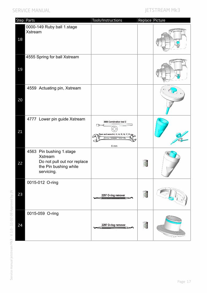
8. ASSEMBLY INSTRUCTIONS - FIRST STAGE
Lubricants shall be used sparingly. Excessive quantities of lubricant can trap particulate and other contaminants developing apotential fire hazard.
Parts marked with the symbol are parts that must be replaced at every service. New parts should be stored in it’s original packing until it is time for assembly.
Step Parts Tools/Instructions Replace Picture
1
4758 Zytel valve seat Xstream
2
0015-059 O-ring
3
0015-012 O-ring
Use bushing 4563 to install o-ring
4
4763 Pin bushing 1.stage Xstream
Make sure fully to the bottom
5
4777 Lower pin guide Xstream
3 +/- 1 Nm
6
4759 Actuating pin, Xstream
Lubricate pin at top section only. Leaving lower end dry. Wipe off excessive grease under the hat.

SERVICE MANUAL
Page 20
Serv
ice
man
ual J
etst
ream
Mk3
- V.
1.0
- 1
1-0
2-0
8 A
ppro
ved
by: J
NJETSTREAM Mk3
Step Parts Tools/Instructions Replace Picture
7
0000-141 Adjusting screw
8
On blindscrew UNF 3/8”0010-353 O-ring, 5 pcs
On blindscrew UNF 7/16”0010-354 O-ring, 2 pcs
9
4552 Cup type filter long
10
4576-BK Wheel G5/8” black
11
0010-354 O-ring
12
4576-BK Line protector, black
13
4778 Conn. stem 1.stage 90
Ensure line protector is correctly positioned, with one slot facing to the bottom of the
housingTorque setting 30 Nm

SERVICE MANUAL
Page 21
Serv
ice
man
ual J
etst
ream
Mk3
- V.
1.0
- 1
1-0
2-0
8 A
ppro
ved
by: J
NJETSTREAM Mk3
Step Parts Tools/Instructions Replace Picture
14
0012-028 O-ring
15
4555 Spring for ball Xstream
Wide end facing upwards, towards the ball.
16
0000-149 Ruby Ball
17
4760 Valve seat holder Xstream4758 Zytel valve seat Xstream
18
4764 Valve seat spring Xstream
19
Pin guide assembly
6 +/- 1 Nm
20
4564 Roll. diaphragm 1.stage Xstream
21
4570-BK Barrier 1.stage black
You should see the marking ”This side up” on
the barrier.
SERVICE MANUAL
Page 22
Serv
ice
man
ual J
etst
ream
Mk3
- V.
1.0
- 1
1-0
2-0
8 A
ppro
ved
by: J
NJETSTREAM Mk3
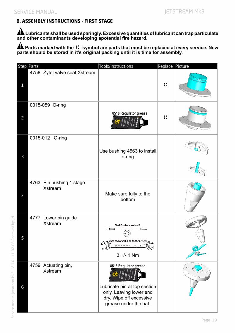
Step Parts Tools/Instructions Replace Picture
22
4565 Pressure plate 1.stage Xstream
23
4763 Adj. spring 1.stage Xstream
6
24
0000-140 Cover Xstream first stage, chrome
25
4568 Screw cover M3x10 Xstream 3 pcs
6 +/- 1 Nm
26
2680 Blindscrew UNF 7/16” 2 pcs
2679 Blindscrew UNF 3/8” 5 pcs
27
Over pressure valve assembly
3726 Valve sealing 3725 Valve piston1180 Pressure spring3727 Locking screw
1. Attach the new valve sealing to the valve piston and place the valve piston in the OP valve hole with the seal towards the housing.
2. Place the pressure spring in the valve piston and tighten the locking screw with a 4 mm Allen key.

SERVICE MANUAL
Page 23
Serv
ice
man
ual J
etst
ream
Mk3
- V.
1.0
- 1
1-0
2-0
8 A
ppro
ved
by: J
NJETSTREAM Mk3 - Mk3
9. SETTINGS AND ADJUSTMENTS
Property 1st stage Setting common units Setting US units
P1 300 bar 4351 psiP2 > 7.5 bar >109 psiP3 20 bar 290 psiP4@p1, 8.5bar 123 psiP5 > 7.5 bar >109 psi i +/- 1.1 bar +/-16 psiR max 1 bar max 15 psiQ 2 L/min 0.07 ft3/minInternal leaktightness 12 ml/h*
* Corresponds to a pressure climb of 0,01 bar/min for a regulator with a 70 cm hose.
1) Open right valve HP (200-300bar)2) Purge3) Check IP (go to item 10 if OK)4) Purge5) Adjust IP (1/2 turn = 1.5 bar)6) Open right valve7) Check IP (loop to 4)8) Close right valve9) Purge10) Open left valve (20 bar)11) Check IP 12) Close left valve13) Purge
FIRST STAGE ADJUSTMENT

SERVICE MANUAL
Page 24
Serv
ice
man
ual J
etst
ream
Mk3
- V.
1.0
- 1
1-0
2-0
8 A
ppro
ved
by: J
NJETSTREAM Mk3 - Mk3
Step Tools/Instructions
1
Connect the Xstrean 1st stage to the test equipment.
Connect the test manometer hose to one of thelow pressure outlets..
Connect the Jetstream 2nd stage to one of thelow pressure outlets on the Xstream 1st stage.
2 Pressurize the 1st stage at maximum tank pressure.
3
Connect the oval connecting pipe on the inhalation resistance gauge to the mouth-pieceon the Octopus.
Test-breathe very carefully. Check the reading of the gauge needle, which should rise to 1.37-1.57 inch (35-40mm)/vp and then move back.The turning point reading equals the inhalation resistance. If the reading is too low, screw the valve tube away from the diaphragm as shown in the picture below. If the reading is too high, screw the valve tube towards the diaphragm.
Tighten up the stop screw.
Repeat the inhalation test again to verify that the inhalation resistance remains the same after the stop screw has been tightned.
ADJUSTMENT OF THE INHALATION RESISTANCE - SECOND STAGE
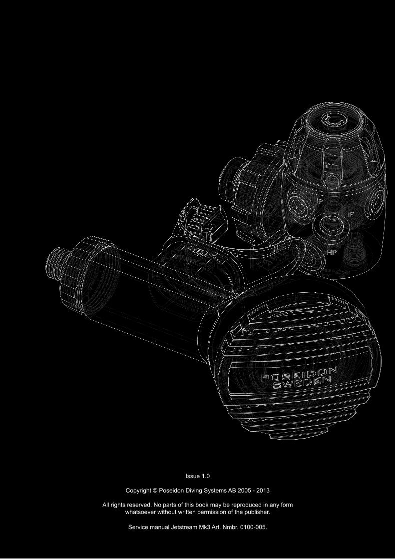
Issue 1.0
Copyright © Poseidon Diving Systems AB 2005 - 2013
All rights reserved. No parts of this book may be reproduced in any form whatsoever without written permission of the publisher.
Service manual Jetstream Mk3 Art. Nmbr. 0100-005.


![Underpressure Agency Military Veterans Bill [B1-2011] Presentation: 31 March 2011](https://img.dokumen.tips/doc/110x75/56649f4f5503460f94c71f8c/underpressure-agency-military-veterans-bill-b1-2011-presentation-31-march.jpg)