Embed Size (px)
Citation preview

WOOD AND COAL CONVECTOR FIRE
Installation and Operating Instructions
Please leave these instructions with the customer
December 2008
Contents Page
Data Table ............................................................................................................................. 1-2
INSTALLATION INSTRUCTIONS
Introduction ............................................................................................................................. 3
Dimensions ....................................................................................................................... 3
Regulations ....................................................................................................................... 3
Important Points To Note Before Starting Installation ....................................................... 3
Flue Outlets ............................................................................................................... 3
Convection Inlet ........................................................................................................ 3
Smoke Gathering ...................................................................................................... 3
Paint .......................................................................................................................... 4
Fire Surround ............................................................................................................ 4
Installation Requirements...................................................................................................... 4
Unpacking ......................................................................................................................... 4
Chimneys .......................................................................................................................... 5
Use of Existing Chimneys ......................................................................................... 5
New Chimney Breasts ............................................................................................... 5
Dimensions ............................................................................................................... 5
Soundness of Flue .................................................................................................... 5
Soot Doors ................................................................................................................ 5
Termination ................................................................................................................ 5
Bends ........................................................................................................................ 6
Flue Gathers ..................................................................................................................... 6
Installation Using an Existing Flue Gather ........................................................................ 6
Installation Using the Jetmaster Flue Gather and Adaptors ............................................. 6
Hearths and Fire Surrounds ............................................................................................. 8
Protection of Heat and Shelves ........................................................................................ 8
Air Supply ......................................................................................................................... 9
Fitting the Firebox ................................................................................................................ 10
Preparation for Fitting ..................................................................................................... 10
Fitting the Firebox Without a Jetmaster Gather ...............................................................11
Fitting the Firebox With a Jetmaster Gather ................................................................... 12
Fitting the Wood Tray and Log Retainer ......................................................................... 14
Fitting the Basket Grate .................................................................................................. 14
Hole in the Wall Installations ........................................................................................... 14
Inglenook Installations .................................................................................................... 14
The Arched Lintel ............................................................................................................ 15
Fillet Plate ....................................................................................................................... 15
Commissioning ..................................................................................................................... 16
After installation is complete ........................................................................................... 16
Air Supply ....................................................................................................................... 16
Smoke Draw Test ............................................................................................................ 16
Notice Plate .................................................................................................................... 16
Cleaning Up .................................................................................................................... 16
Lighting After Installation ................................................................................................. 16
Chimney Sweeping ......................................................................................................... 16
Handing Over .................................................................................................................. 17

USERS INSTRUCTIONS
General ................................................................................................................................ 18
Warnings ......................................................................................................................... 18
Safety Information ................................................................................................................ 18
Chimney Sweeping ......................................................................................................... 18
Chimney Fires ................................................................................................................. 18
How do I know when I have a chimney fire? .................................................................. 18
What should I do if I have a chimney fire? ...................................................................... 18
Important ......................................................................................................................... 19
Protection of Heat and Shelves ...................................................................................... 19
Operating Instructions ......................................................................................................... 20
Lighting after Installation ................................................................................................. 20
Wood Burning Trays and Basket Grates ........................................................................ 20
Wood Burning Tray ......................................................................................................... 20
Lighting with Wood Burning Tray .................................................................................... 20
Basket Grates ................................................................................................................. 20
Lighting with Basket Grate .............................................................................................. 21
Use of the Throat Restrictor ............................................................................................ 21
Fuels ............................................................................................................................... 21
Recommended Fuel Types ............................................................................................. 22
Smokeless Fuels ..................................................................................................... 22
Wood ....................................................................................................................... 22
Peat ......................................................................................................................... 22
Gas .......................................................................................................................... 22
Fire Screens ................................................................................................................... 22
Servicing Instructions .......................................................................................................... 23
Important ......................................................................................................................... 23
Servicing ......................................................................................................................... 23
Removal and Replacement of Throat Restrictors ........................................................... 23
Cleaning and Maintenance ............................................................................................. 24
Jetmaster Guarantees .......................................................................................................... 24
Jetmaster Provides Two Guarantees .............................................................................. 24
Two Year Guarantee (Registerable on Gas Fires) .......................................................... 24
Ten Year Guarantee (Registerable) ................................................................................ 25
Terms and Conditions ..................................................................................................... 25
Statutory Rights .............................................................................................................. 26
Complain ts .................................................................................................................... 26
Specifications .................................................................................................................. 26
Trademark ....................................................................................................................... 27
Contact Details ............................................................................................................... 27

1
DIMENSIONS STANDARD UNIVERSAL LOW EXTRA
MODEL 16 18 500 600 700 500 600 700 700 850 1050
FRAME
WIDTH A mm 453 503 600 700 800 600 700 800 800 950 1150
ins 17 5/8 19 5/8 23 5/8 27 1/2 31 1/2 23 5/8 27 1/2 31 1/2 31 1/2 37 1/2 45 1/2
HEIGHT B mm 576 576 650 650 650 550 550 550 700 750 800
ins 22 5/8 22 5/8 25 5/8 25 5/8 25 5/8 21 5/8 21 5/8 21 5/8 27 1/2 29 1/2 31 1/2
FIREBOX
WIDTH C mm 398 448 550 650 750 550 650 750 750 900 1100
ins 15 5/8 17 5/8 21 5/8 25 5/8 29 1/2 21 5/8 25 5/8 29 1/2 29 1/2 35 1/2 43 3/8
HEIGHT D mm 549 549 630 630 630 530 530 530 680 730 780
ins 21 5/8 21 5/8 24 3/4 24 3/4 24 3/4 20 7/8 20 7/8 20 7/8 26 3/4 28 3/4 30 3/4
DEPTH E mm 350 350 355 355 355 355 355 355 405 455 505
ins 13 3/4 13 3/4 14 14 14 14 14 14 16 18 20
OPENING REQUIRED
WIDTH mm 407 457 580 680 780 580 680 780 780 930 1130
Ins 16 18 22 7/8 26 3/4 30 3/4 22 7/8 26 3/4 30 3/4 30 3/4 36 5/8 44 1/2
HEIGHT mm 559 559 635 635 635 535 535 535 685 735 785
ins 22 22 25 25 25 21 21 21 27 29 31
DEPTH mm 356 356 365 365 365 365 365 365 415 465 515
ins 14 14 14 3/8 14 3/8 14 3/8 14 3/8 14 3/8 14 3/8 16 3/8 18 3/8 20 3/8
WEIGHT Kg 37 45 53 59 68 53 59 68 76 99 133
OUTPUTS / EFFICIENCY /
TEMPERATURES
WOOD TRAY with WOOD
ROOM SIZE HEATED M³ 57 70 130 150 170 70 130 150 175 200 250
HEAT OUTPUT TO ROOM
WOOD (Tested to BS3250)
KW 2.9 3.6 6.5 7.5 8.5 5.0 6.5 7.5 9.5 14.9 17
TOTAL NOMINAL HEAT OUTPUT WOOD
WHEN TESTED TO EN13229: 2001
kW 5.5 8.5 15 20 X X X X X X X
NET EFFICIENCY WOOD
TO EN13229: 2001
% 49.7 46.7 46.7 46.7 X X X X X X X
FLUE GAS TEMPERATURE
TO EN13229: 2001
°C 187 <380 <380 380 X X X X X X X
FLUE GAS MASS FLOW
TO EN13229: 2001
gs¯¹ 28.9 X X 61.9 X X X X X X X
MEAN CO2 IN FLUE GAS
TO EN13229: 2001
% 2.42 X X 5.12 X X X X X X X
MEAN CO @ 13% O2
TO EN13229: 2001
% 0.35 0.35 0.35 0.17 X X X X X X X

DIMENSIONS STANDARD UNIVERSAL LOW EXTRA
OUTPUTS / EFFICIENCY TEMPERATURES
BASKET with SMOKELESS FUEL
HEAT OUTPUT TO ROOM
SMOKELESS FUEL
(Tested to BS3250)
kW 2.9 3.2 5.1 5.8 6.6 4.0 5.1 5.8 6.7 10.1 12
TOTAL NOMINAL HEAT OUTPUT
SMOKELESS FUEL WHEN TESTED TO
EN13229: 2001
kW 5.9 X X X X X X X X X X
NET EFFICIENCY SMOKELESS FUEL
TO EN13229: 2001
% 52.3 X X X X X X X X X X
FLUE GAS TEMPERATURE
TO EN13229: 2001
°C 210 X X X X X X X X X X
FLUE GAS MASS FLOW
TO EN13229: 2001
gs¯¹ 23.8 X X X X X X X X X X
MEAN CO2 IN FLUE GAS
TO EN13229: 2001
% 2.73 X X X X X X X X X X
MEAN CO @ 13% O2
TO EN13229: 2001
% 0.51 X X X X X X X X X X
OUTPUTS / EFFICIENCY TEMPERATURES
BASKET with WOOD
TOTAL NOMINAL HEAT OUTPUT WOOD
WHEN TESTED TO EN13229: 2001
kW 18 X X 23.4 X X X X X X X
NET EFFICIENCY WOOD
TO EN13229: 2001
% 52.6 X X 40.3 X X X X X X X
FLUE GAS TEMPERATURE
TO EN13229: 2001
°C 400 X X 375 X X X X X X X
FLUE GAS MASS FLOW
TO EN13229: 2001
gs¯¹ 37.5 X X 83.8 X X X X X X X
MEAN CO2 IN FLUE GAS
TO EN13229: 2001
% 6.15 X X 4.15 X X X X X X X
MEAN CO @ 13% O2
TO EN13229: 2001
% 0.19 X X 0.18 X X X X X X X
RECOMMENDED FLUE
SQUARE mm (int.) 185 185 185 185 200 185 185 185 200 250 300
ins (int.) 7 1/4 7 1/4 7 1/4 7 1/4 8 7 1/4 7 1/4 7 1/4 8 10 12
ROUND mm (int.) 180 200 200 200 200 200 200 200 225 250 300
ins (int.) 7 8 8 8 8 8 8 8 9 10 12
MINIMUM FLUE
MINIMUM FLUE ROUND mm (int.) 155 180 180 190 200 180 185 190 225 250 300
in (int.) 6 7 7 7 1/2 8 7 7 1/4 7 1/2 9 10 12
MINIMUM FLUE AREA cm2 190 250 250 285 315 250 267 285 366 507 730
in2 30 38 38 44 50 38 42 44 57 79 113
MINIMUM FLUE DRAUGHT Pa 10 10 10 10 X 10 10 X X X X
CHIMNEY HEIGHT
ABOVE FIRE M 4.6 4.6 5.5 5.5 5.5 5.5 5.5 5.5 5.5 6.0 7.2
ft 15 15 18 18 18 18 18 18 18 20 24
AIR SUPPLY
cm2 170 170 230 230 230 230 230 230 230 350 500
in2 26 26 36 36 36 36 36 36 36 55 78
DIMENSIONS STANDARD UNIVERSAL LOW EXTRA
MODEL 16 18 500 600 700 500 600 700 700 850 1050
FRAME
WIDTH A mm 453 503 600 700 800 600 700 800 800 950 1150
ins 17 5/8 19 5/8 23 5/8 27 1/2 31 1/2 23 5/8 27 1/2 31 1/2 31 1/2 37 1/2 45 1/2
HEIGHT B mm 576 576 650 650 650 550 550 550 700 750 800
ins 22 5/8 22 5/8 25 5/8 25 5/8 25 5/8 21 5/8 21 5/8 21 5/8 27 1/2 29 1/2 31 1/2
FIREBOX
WIDTH C mm 398 448 550 650 750 550 650 750 750 900 1100
ins 15 5/8 17 5/8 21 5/8 25 5/8 29 1/2 21 5/8 25 5/8 29 1/2 29 1/2 35 1/2 43 3/8
HEIGHT D mm 549 549 630 630 630 530 530 530 680 730 780
ins 21 5/8 21 5/8 24 3/4 24 3/4 24 3/4 20 7/8 20 7/8 20 7/8 26 3/4 28 3/4 30 3/4
DEPTH E mm 350 350 355 355 355 355 355 355 405 455 505
ins 13 3/4 13 3/4 14 14 14 14 14 14 16 18 20
OPENING REQUIRED
WIDTH mm 407 457 580 680 780 580 680 780 780 930 1130
Ins 16 18 22 7/8 26 3/4 30 3/4 22 7/8 26 3/4 30 3/4 30 3/4 36 5/8 44 1/2
HEIGHT mm 559 559 635 635 635 535 535 535 685 735 785
ins 22 22 25 25 25 21 21 21 27 29 31
DEPTH mm 356 356 365 365 365 365 365 365 415 465 515
ins 14 14 14 3/8 14 3/8 14 3/8 14 3/8 14 3/8 14 3/8 16 3/8 18 3/8 20 3/8
WEIGHT Kg 37 45 53 59 68 53 59 68 76 99 133
OUTPUTS / EFFICIENCY /
TEMPERATURES
WOOD TRAY with WOOD
ROOM SIZE HEATED M³ 57 70 130 150 170 70 130 150 175 200 250
HEAT OUTPUT TO ROOM
WOOD (Tested to BS3250)
KW 2.9 3.6 6.5 7.5 8.5 5.0 6.5 7.5 9.5 14.9 17
TOTAL NOMINAL HEAT OUTPUT WOOD
WHEN TESTED TO EN13229: 2001
kW 5.5 8.5 15 20 X X X X X X X
NET EFFICIENCY WOOD
TO EN13229: 2001
% 49.7 46.7 46.7 46.7 X X X X X X X
FLUE GAS TEMPERATURE
TO EN13229: 2001
°C 187 <380 <380 380 X X X X X X X
FLUE GAS MASS FLOW
TO EN13229: 2001
gs¯¹ 28.9 X X 61.9 X X X X X X X
MEAN CO2 IN FLUE GAS
TO EN13229: 2001
% 2.42 X X 5.12 X X X X X X X
MEAN CO @ 13% O2
TO EN13229: 2001
% 0.35 0.35 0.35 0.17 X X X X X X X
2

Installation Instructions
IntroductionREAD THESE INSTRUCTIONS CAREFULLY BEFORE STARTING THE INSTALLATION.
CLOSE ATTENTION TO THE DETAILS OF INSTALLATION WILL ENABLE YOU TO GET
THE BEST RESULTS FROM YOUR FIRE.
NOTE: THESE INSTRUCTIONS SHOULD BE RETAINED FOR FUTURE REFERENCE.
There are three essential requirements for a successful installation.
A. The fire must be correctly fitted into the recess and surround.
B. The chimney must be of correct dimensions, be suitable for use with open fires and be
terminated clear of any possible wind effects.
C. There must be an adequate air supply of air into the room.
Dimensions
The table of installation data on pages 1 & 2 contains all the dimensional information necessary
to allow the installation to be properly planned.
Regulations
In the United Kingdom the installation must be in accordance with:-
• The Building Regulations issued by the Department of the Environment or the Building
Standards (Scotland) (Consolidation) Regulations issued by the Scottish Development
Department.
• All relevant codes of practice and relevant parts of any local regulations, including those
referring to National and European standards.
In your own interest and for safety, in the United Kingdom, it is the law that all solid fuel
appliances are installed by competent persons. The Heating Equipment Testing and Approval
Scheme (HETAS) require its members to work to recognised standards.
In other countries the installation must also conform to the national and local regulations in
force. This may include only the use of permitted fuels in some countries.
Important Points to Note Before Starting Installation
Flue Outlets
Flow from the outlets must be totally free from any obstruction.
Convection Inlet
This must never be restricted. The fire can be fitted on a small plinth for aesthetic reasons also
this will help prevent the ingestion of any ash from the hearth into the air inlet.
Smoke Gathering
The smoke from the two outlets must be gathered in as smooth a manner as is possible into the
flue, which is to serve the fire. Steps caused by lintels etc. that can cause eddies in the smokeway,
should be chamfered away, or, if space allows, filleted over to form smooth profiles.
3

Paint
The frame of the fire may require to be painted after installation to freshen the ‘keeper’ coat
with which the fire is supplied. It is strongly recommended that the shot blast finish on the frame
etc. is protected from cement and plaster splashes during installation, as these are difficult to
remove from the textured surfaces.
Fire Surrounds
Some fire surrounds require the fire to be set forward from the chimney breast or to be raised
for aesthetic reasons. Ensure that these requirements are taken into account when positioning
the fire.
Installation RequirementsThe minimum height of any flue must be 4.6m measured from the top of the firebox for the 16”
and 18” standard fires. As the fire size opening becomes larger then the height will increase.
Please see the installation data table on pages 1 & 2.
The flue must not be used for any other appliance or application.
If a Jetmaster gas conversion kit is ever fitted in the firebox the damper or throat restrictor should
be removed. If removal is not possible, it must be permanently secured in the open position.
This must be in line with the Gas safety (Installation & Use) Regulations.
Any under floor vents or openings within the builders opening should be sealed off.
The surface of the hearth and fireplace floor must be sufficiently flat to ensure that a good seal
with the firebox can be made. Any excessive unevenness (uneven tiles, stone, etc.) should be
rectified.
The front face of the fireplace should be reasonably flat over the area covered by the firebox top
and side flange seals to ensure good sealing. These faces should be made good if necessary.
The appliance must not stand on combustible materials or carpets.
Unpacking
The Convector fire and the following components are packed in several cartons. Take care
when unpacking the fire to avoid accidental damage.
Ensure that all the listed items are present before commencing installation.
• Firebox.
• Poker
• Insulation
• Installation & Operating Instructions.
• Damper spanner
• Guarantee card
• Firescreen
Either:-
A - Wood Tray and Log Retainer
B – Basket Grate and Ashpan
4

Chimneys
New chimneys may be constructed using chimney blocks, insulated tubular sections or clay
liners within brick or stone. Weather the chimney is old or is newly built, its dimensions must
be adequate to support the size of fire to be installed. The larger the fire, the greater the size of
flue and the taller the chimney required. When specifying flue liners, ensure that the important
internal dimensions are stated. Some fires may operate successfully on flues smaller than
the recommended sizes, but this is normally only the case when the flue height is significantly
greater than the minimum recommended. No data is available for this calculation.
Use of Existing Chimneys
These must be swept and inspected for dimensions and soundness before starting to install
the fire.
New Chimney Breasts
Where a new chimney breast is to be built, the Jetmaster flue gather and adapter may be used
in achieving connection to the flue. The components are available for Universal, Low and Extra
Units
Dimensions
See the installation data table on pages 1 & 2 for recommended flue size and minimum chimney
height.
Soundness of Flue
The flue must be sound and free from cracks and obstructions. New flues must be lined.
All flues should be swept clean prior to installation and inspected for soundness and freedom
from blockages.
Soot Doors
The Fires are provided with removable throat restrictors to facilitate chimney sweeping and for
the removal of soot from the top of the unit. However, the provision of a soot door into the flue
will make sweeping easier.
In inglenooks where register plates are fitted, a soot door should be provided in the register for
cleaning out soot falls above this level. On outside walls, an external soot door can be fitted so
the chimney can be swept from the outside. The throat restrictor flap can then be closed during
sweeping and the soot removed by vacuum (from above).
Termination
The top of the flue should be well clear of turbulence and downdraught and preferably higher
than any overshadowing building or tree within 15m. Building regulations stipulate minimum
clearance above windows and ventilation openings. Pots should be simple, open topped and
with the same internal diameter as the flue. Unconventional pots or terminals must be so
designed that will operate satisfactorily in all wind directions. Take steps to prevent birds nesting
in the terminal.
5

Bends
The ideal flue is straight and vertical. New chimneys must not deviate more than 45º from the
vertical, but it is desirable that the deviations do not exceed 30º. Bends greater than 30º are not
allowed in pre-fabricated metal chimneys. In older chimneys bends exceeding 45º may be found
and will degrade flue performance, particularly by allowing soot deposits to accumulate in the
angles. In new flues it is essential to check that no
builders material has been left in the bends.
Flue Gathers
All fires need some type of gather to channel
the smoke to the base of the flue. If there is no
existing gather then one needs to be provided.
Gathers may be constructed from bricks, blocks
etc or can be a proprietary cast gather or fire chest.
Alternatively the Jetmaster gather may be fitted. In
nearly all cases where a gather needs to be fitted
to an existing flue then the chimney breast will
need to be cut into.
The Jetmaster fire is not a structural unit, although
very robust it is not designed to take the weight
of the flue. Therefore a structural lintel will need
to be provided for clay liners or the use of a fire
chest with built in gather lintel or in the case of pre
fabricated stainless steel chimney the chimney
manufactures recommended fixing brackets or
method must be used.
Installation Using an Existing Flue Gather
If the existing masonry gather is to be used to
channel the smoke into the flue from the top of the
fire, it must be smooth and in good condition. The
flue dimensions must be reached at least 200mm
above the top of the fire, where the flue exit is
central, and at least 500mm above the fire where
the flue exit is to one side. The shoulders of the
gather should not be at an angle of more than 45º
from vertical.
Installation Using the Jetmaster Flue
Gather and Adaptors
The Jetmaster Flue Gather and adaptor is a convenient way of achieving the efficient transfer
of smoke from the fire unit to the flue. It may be used bolted onto the firebox and the assembly
slid under the flue as shown in the diagram below. The use of a small plinth as shown in the right
hand example is recommended, as this minimises any ingestion of dust into the convected air.
6

FIRE Dim. F Dim. G Dim. H Dim. J Dim. K Dim.L
Universal/Low 500 215 250 140 144 0 251.5
Universal/Low 600 215 275 140 144 0 251.5
Universal/Low 700 215 325 140 144 0 251.5
Extra 700 215 325 178 156 34 263.5
Extra 850 265 380 219 165 25 297.5
Extra 1050 315 455 259 175 15 332.5
FIRE Dim. F Dim. G Dim. H Dim. J Dim. K Dim.L
Universal/Low 500 215 250 140 284 144 391.5
Universal/Low 600 215 275 140 284 144 391.5
Universal/Low 700 215 325 140 284 144 391.5
Extra 700 215 325 178 296 106 403.5
Extra 850 265 380 219 305 115 437.5
Extra 1050 315 455 259 315 125 472.5
7

The flue gather is not designed to support the chimney or its liners.
Normally the gather would be used in conjunction with one of the adapters, which are available
in several forms.
Type A - Forms a receptacle for the spigot of a standard size flue liner 200mm square.
Type B - Accepts the 225mm circular liner.
Type C - Is sized for nominal 200mm diameter vitreous or stainless steel flue pipe and for
200mm double skinned flexible stainless steel flue liners.
Type D - Is sized for export
Type E - Accepts the 175mm circular liner.
Type F - Accepts the 200mm circular liner.
When raised into position below the flue liner, the adapter may be supported by drilling and screw
fixing, or by use of the special adapter clamp. The adaptor has 25mm of vertical movement to
take up small variations in height.
Large adapters of similar design are available for E850 and E1050 fires. These are based upon
250mm and 300mm internal flue dimensions.
Hearths and Fire Surrounds
The floor or recess on which the fire stands shall have adequate load bearing capacity. Particular
attention shall be paid to existing constructions.
New hearths, fireplaces recesses and chimneys should be constructed to conform to Building
Regulations Part J.
Hearths, or plinths constructed to support the fire above the hearth, must be horizontal. Some
fire surrounds will require the fire to be set above hearth level, or forward of the chimney breast.
The Jetmaster decorative contemporary frame requires sufficient clearance around the firebox
to allow for the frame to fit flush with the fireplace surround. Take this into account when forming
the recess and front finished face of the fireplace for the fire.
Protection of Heat and Shelves. (Not tested under conditions of EN13229)
As on all heat producing appliances the use of flammable wall coverings directly above or to the
sides of the fire may lead to a fire hazard. Please bear this in mind when installing the appliance
or decorating.
If in doubt always consult the building regulations regarding the proximity of combustible
materials.
8

The minimum height from the top surface of the frame of the fire to the underside of any shelf
shall be as follows.
For a shelf depth of 100mm (4”) from wall – Minimum height = 300mm (12”)
For shelves of a greater depth add 50mm (2”) to the shelf height for every 25mm (1”) increase
in shelf depth.
These are Jetmaster estimated distances, in certain cases further protection may be required
to guard against heat on combustible materials, such as increasing the shelf height or shielding
with a non combustible material.
This is because of the variability of the heat produced from a solid fuel fire. It is dependent on the
quantity of fuel used and the refuelling frequency. A comparable gas or electric fire has a known
fixed input and thus a fixed output.
Air Supply
All fires require a supply of air to support combustion and to allow the chimney to draw correctly.
Air starvation will result in poor flue draw and smokiness in the room. All installations will
require a permanent dedicated air supply for the fire. Newly constructed houses, especially
those using double-glazing and employing modern draught control techniques, will need careful
planning of air entry. The size of air supply duct or ducts recommended for each fire is shown in
the installation data table pages 1 & 2.
The building regulations Part J and L must be taken into account when providing
ventilation for the fire.
Extractors or fans when operated in the same room or adjoining room of the fire may cause
problems.
If there is a fan or extractor fitted in the property then allowance for additional air may be
required.
See commissioning section.
If there is more than one appliance in the property then each appliance must be supplied with
adequate combustion air and ventilation so that all the appliances can operate simultaneously.
Bring air in to the room close to the fire. The ideal position is just to the sides of the fireplace
opening as shown. It can be split and brought up in two positions if required, one each side of
the fireplace opening.
9

DO NOT set a ventilation grille in the hearth immediately in front of the fire. The cold air entering
the room will form a cold ‘curtain’ in front of the fire and may destroy the convection of warm air
around the room.
DO NOT place an air supply inlet across the room from the fire. The draught of cold air crossing
the room will scour the room of warm air and the overall heating effect of the fire will be
reduced.
DO NOT set a ventilation grille in a position where they may become liable to blockage.
Where possible, draw air from two walls at right angles and duct to a mixing chamber beneath
the floor before it enters the room. This will reduce the influence of strong winds on the supply
of air. Where an existing floor is solid, vents may have to be provided through the walls in a
manner, which achieves conditions as close as possible to the above, perhaps, by the use of
ducting or of false skirting.
Where there is a suspended floor over a well ventilated under floor space, it may be sufficient
just to set ventilation openings through the floorboards adjacent to the chimney breast. Older
houses with the possibility of draughts entering around doors and windows will still profit from the
provision of a separate air supply as, properly placed, this will stop or reduce cold draughts.
When bringing in the air supply consideration should be given to any regulations that would
effect the position of any ducting or ventilation grilles.
Fitting the Firebox
Preparation For Fitting
If installing the fire in an existing fireplace, first remove all loose material from the recess and
measure the opening and recess to ensure that the Jetmaster fire will fit. The opening must be
high enough to allow the fire, and the flue gather if used, to be put into position, and must be
sufficiently wide to permit the fire and its insulation to pass through. The recess must be large
enough to provide a clearance of 20 - 40mm (¾” - 1½”) around the sides and back of the fire.
Cut away or build up to achieve the desired dimensions. Alternative methods of creating the
required recess size are shown in the diagram below.
Where the recess is to be newly built, form the recess to give a clearance around the sides and
back of the fire of 20 - 40mm (¾” - 1½”) to accommodate the insulation.
For details of opening sizes required. See table on pages 1 & 2.
Where the sides or back of the recess have to be built up, and the masonry flue gather of the
chimney is to be used, build up to the height of the fire only and then top with a sloping fillet of
mortar to deflect any soot fall into the top of the fire.
Check that the hearth, or new plinth where this is constructed, is horizontal.
Check that the two flue outlets on top of the fire will not be restricted.
The fire surround should be flat around the sealing area of the fire. The hearth and fireplace
opening must be flat and at the same level.
10

Fitting The Firebox Without A Jetmaster Gather
Place the fire in front of the prepared opening. Wrap the sides and back of the fire with the
insulation and hold this in place with tape.
Slide the fire into position in the prepared recess, taking care not to snag the insulation on the
sides of the opening.
Where the opening is significantly higher than the fire, the space may be filled by brickwork.
Place a layer of insulation beneath the bricks to provide an expansion joint on top of the fire. If
more than three or four courses of brick are needed, these should be supported on a lintel or
steel bar between the jambs.
A tight and effective seal must be made all round the front of the firebox. Where slate or
marble slips are used, these should be placed behind the frame to form a sliding contact and
thus allow for the expansion of the fire. Do not allow slips, marble, plaster or brickwork etc to
abut the edge of the frame or to have direct contact with the firebox as expansion of the fire
may cause them to crack. Use a strip of insulation as an expansion joint where necessary. The
box can be sealed to the opening using the insulation supplied, or similar material in either
position shown in the diagram below. A way of achieving this is to cut off a strip of the insulation
supplied and double it over until the required thickness is achieved to form an effective seal. An
alternative way is to use a proprietary ceramic rope seal of the correct size. If the front of the fire
is not sealed, air can leak into the flue and chimney performance will be impaired. The object is
to form a dry seal that will stay flexible moving with the box as it expands and contracts, yet still
keep the firebox sealed to the fireplace opening.
11

Fitting The Firebox With A Jetmaster Gather
The fitting of the firebox with the Jetmaster gather is similar to that when fitting with a concrete
gather. However, the recess must be high enough to allow the fire, and the Jetmaster gather to
be slid into position. This will involve breaking into the front of the chimney breast.
Place the fire with the gather attached in front of the prepared opening. Wrap the sides and back
of the fire/gather with the insulation and hold this in place with tape.
Slide the fire/gather into position in the prepared recess, taking care not to snag the insulation
on the sides of the opening. Once in situ then the adaptor can be joined to the flue. See section:-
Installation Using The Jetmaster Flue Gather And Adaptors. The front of the chimney-breast can
then be infilled and the cavity around the gather may be wrapped with flexible insulation or back
filled with vermiculite cement. Use strips of insulation as expansion joints where necessary.
A tight and effective seal must be made all round the front of the firebox. The box can be
sealed using the insulation supplied, in a similar manner to that Without a Jetmaster Gather. If
the front of the fire is not sealed, air could leak into the flue and chimney performance will be
impaired. The object is to form a dry seal that will stay flexible moving with the box as it expands
and contracts, yet still keep the firebox sealed. It will also help against the possibility of curing
paint fumes escaping into the room.
12

An alternative use for the Jetmaster gather is to form a permanently fixed shuttering, supported
by masonry piers. Gather support brackets may be made and fixed to the sloping sides of the
gather at a height suitable for the piers. The cavity above the gather may be wrapped with
flexible insulation or back filled with vermiculite cement.
The fire may then be slid beneath the gather and sealed in a similar manner to that without a
Jetmaster Gather.
It is essential that the system be sealed at each joint so that the only air, which can reach the
flue, is that which enters through the front of the fire. Once the sealing has been carried out,
the chimney breast may be infilled with block work. The firebox, using an expansion joint or
resilient insulation, may support three or four courses of brick but any greater quantity should be
supported on a lintel or steel bar between the jambs.
Some fires, when installed on very smooth surfaces have a tendency to creep forward after
a period of use. If this happens it can degrade the sealing arrangements and impair the flue
draw.
To prevent this a pair of pins, say 5mm in diameter may be sunk into the hearth and left to
protrude by 3mm. A matching pair of holes drilled into the base of the convection air inlet will
enable the fire to be pushed back and engaged over the pre-fitted pins.
13

Fitting the Wood Tray and Log Retainer
Slide the wood tray into the firebox. The wood tray should be fitted with the centre leg towards
the rear of the firebox. Once in position the log retainer can be attached to the front of the wood
tray. The clips on the rear of the retainer should clip over the front of the tray and the lugs at each
end of the retainer will locate behind the firebox frame each side.
Fitting the Basket Grate
The basket can be slide into the firebox centrally. It should be pushed back to the rear of the
firebox and then pulled foreword slightly by a few millimetres to allow a small air space between
the rear of the basket and the inside back of the firebox. Fit the bottom grid into the basket and
slide the ashpan under the basket.
Hole - In - The - Wall Installations
When fitting as a hole in the wall fire the following should be taken into account.
Installations without overhead mantle may be subject to hot air staining above the fire in the
same manner as a wall above a radiator.
If fitting the Jetmaster contemporary decorative frame then sufficient clearance should be
allowed around the outside of the fire for the frame to fit flat to the wall. The distance from the
top of the hearth to the underside of the firebox should be 95mm minimum.
Any hole in the wall installation will still require a hearth to be fitted.
Inglenook Installations
The fire should be set within a brick or stone recess, built within the inglenook and extending at
least to the height of the top of the flue gather. For the best possible results, the flue connection
from the top of the fire to the chimney should be made with flue liners or flue pipe sealed in to
the existing chimney where it narrows. The inglenook above the lintel should then be sealed with
a non-combustible register, or ceiling, to prevent heat loss into this space.
14

Where direct connection of the flue from fire to chimney cannot be achieved, the flue liners
or flue pipe should be taken up as high as possible within the narrowing inglenook chimney,
to extend at least 2 metres (6 ft 6 in) above the register plate level. In this case the register
plate should be made of steel or aluminium and a removable section should be incorporated,
of adequate size to allow access for inspection and cleaning. The register must be air tight and
sealed around the edges, the flue connection passing through it and the inspection access
cover. The register should be supported on a framework of steel or aluminium.
Flue liners or flue pipe used must be of the correct size for the fire and must be suitable for use
with open fires. Flue pipes of aluminium or asbestos may not be used, nor may flexible pipes of
aluminium or single wall stainless steel.
The Arched Lintel
Secured to the top of the fire, the arch lintel extends 100mm (4”) in front of the frame to form
an arched support for a brick or stone facing. It can be of particular use where a deep lintel
supporting the chimney breast prevents the fire being set fully forward in the opening.
A resilient gasket, such as glass fibre, should be interposed between the fire structure and the
lintel, and between lintel and facing material, to allow movement under varying temperature and
to ensure that a seal is formed preventing air leakage into the flue if a gather is not used.
It is possible to use both an arched lintel and a Jetmaster steel flue gather.
Fillet Plate
Where the installation is to be carried out into
an existing opening which is already gathered
starting at a height not more than above
600mm above the top of the unit to be fitted, it
is not necessary to utilise the Jetmaster gather.
However, it is essential to create fillets just above
the top of the fire to prevent any falling soot or
debris from settling on top of the insulation and
any infill blockwork. This is particularly important
to the rear of series 5 Jetmaster fires that have
the 70mm chamfer at the top of the firebox.
There is an optional accessory available which
may be fitted by drilling two holes in the side of
the smoke outlets. This fillet plate enables a rear
fillet to be achieved with minimum effort and over
a range of rear clearance.
15

CommissioningAfter Installation Is Complete
In your own interest and for safety, in the United Kingdom, it is the law that all solid fuel
appliances are installed by competent persons. The Heating Equipment Testing and Approval
Scheme (HETAS) require its members to work to recognised standards.
Air Supply
When commissioning the fire ensure that the air supply is adequate for the fire. Particular
attention should be observed if there is an extractor or fan in the room or adjoining room as this
may have an effect on the draw of the flue / fire. The fire should be tested with the extractor fan
on and with all inter-connecting doors to the room closed and then open. If required additional
air may be required to overcome the extractor or fan pressure.
Smoke Draw Test.
Ensure appliance is not alight.
Warm chimney for 10 minutes using a blowlamp or similar heating device.
Place a smoke pellet in the wood tray or basket grate towards the front of the opening of the fire
and ignite the pellet.
Check that the smoke is being drawn into the fire and flue and that it is discharging satisfactory
at the flue terminal.
Notice Plate
Ensure that any notice plate is provided in line with the building regulations J4. The notice
should contain information on the performance characteristics of the hearth, fireplace, flue or
chimney and is to be fixed in an appropriate place.
Cleaning Up
Immediately after installation, the visible parts of the fire should be cleaned up and painted
with a heat resistant matt black paint. Thereafter, the surfaces may be kept clean by using a
light brush to remove dust and by occasional wiping with a lint-free cloth. Annual repainting is
recommended. Do not use black leading or paint the interior of the firebox.
Lighting after installation
The Jetmaster should not be lit until all cement and plasterwork is completely dry and cured.
When installation has involved building in cement mortar allow:-
a. 7 days drying time if the house has other forms of heating.
b. At least 14 days if the installation is in a new or unoccupied property, or is fitted into a
completely new chimney breast.
Chimney Sweeping
We recommend that flues should be swept at least twice a year, during the heating season.
More frequent sweeping may be necessary where fires are burned throughout the year or where
low grade wood or bituminous coal are used as fuels. Fires are provided with removable throat
restrictors to facilitate chimney sweeping and for the removal of soot from the top of the unit.
A small boss flue brush head that will fit to standard rods may be required for the smaller
fires. These brush heads should be available from any good hardware store or through your
Jetmaster distributor. See Servicing Instructions.
16

Handing Over
- Read the Users instructions and instruct the user on the operation of the fire and cleaning
methods. Leave instructions with the user.
- The user should be told that any odours are due to the newness of materials and should
disperse after a few hours operation.
- The user should be informed that the fire should be serviced annually and the chimney
checked for flue pull and blockage.
Advice the customer on the operation of the flue damper
Advice the customer on the importance of an adequate air supply
Advice the customer on the importance of regular servicing and chimney sweeping
17

Users Instructions
THESE INSTRUCTIONS SHOULD BE READ CAREFULLY AND RETAINED FOR
FUTURE REFERENCE.
GeneralWARNING - NEVER HANG CLOTHES OR OTHER ITEMS OVER THE APPLIANCE.
This appliance is designed for intermittent operation and is intended for the purposes of
room heating. It is designed to burn only the recommended fuels specified by Jetmaster
and shall not be used with any liquid fuels or as an incinerator.
In the United Kingdom the installation must be in accordance with:-
• The Building Regulations issued by the Department of the Environment or the Building
Standards (Scotland) (Consolidation) Regulations issued by the Scottish Development
Department.
• All relevant codes of practice and relevant parts of any local regulations, including those
referring to National and European standards.
• In other countries the installation must also conform to the national and local regulations in
force. This may include only the use of permitted fuels in some countries.
The fire is suitable for hearth installation only. The hearth should be non-combustible and to the
requirements and size as detailed in part J of the Building Regulations. A typical thickness of a
superimposed hearth is 48mm
Due to the newness of materials, the fire may give off a slight smell for a period after initial
lighting. This is quite normal and any odours will disperse after being used a few times.
Safety InformationChimney Sweeping
Chimneys should be swept at least twice a year during the burning season. More frequent
sweeping may be necessary where fires are burned throughout the year or where low grade
wood or bituminous coal are used as fuels. Fires are provided with demountable throat restrictors
to facilitate chimney sweeping.
Chimney Fires
How Do I Know When I Have A Chimney Fire?
Excessive amounts of smoke.
Embers falling down the chimney
A roaring noise
Brickwork around the chimney can be very hot.
What Should I Do If I Have A Chimney Fire?
Raise the alarm in the house to let others know.
Call the Fire Service.
Reduce the burning rate of the fire by closing down the throat restrictor in a controlled way so
not to let fumes discharge into the room.
18
Close any ventilation as much as possible.
Place the spark guard in front of the fire.
Move furniture and rugs away from the fireplace.
Feel the chimney breast in other rooms for signs of excessive heat.
Remember chimney fires can spread to the rest of the property always call the fire service -
Never tackle a fire yourself.
Get Out – Stay Out
IMPORTANT:
If you have not already done so, FIT A SMOKE ALARM.
The chimney should be swept before the appliance is installed.
The chimney should be checked regularly to ensure correct evacuation of the flue
products particularly after a prolonged shutdown period.
The use of flammable wall coverings directly above or to the sides of the fire may lead to a fire
hazard. Please bear this in mind when installing or decorating.
Always allow the fire to cool before touching any parts except for those that are designed to
operate with a tool. Note that the residual heat in the fuel will remain hot for a considerable
length of time.
The hot air outlet must not be obstructed by hanging clothing etc. over the hood.
DO NOT touch the external surfaces, air outlet or hood when the fire is alight as these surfaces
become hot.
DO NOT modify the appliance in any way. ONLY modifications authorised by Jetmaster may
be carried out.
Only genuine Jetmaster replacement parts shall be used.
A suitable fireguard conforming to National Regulations should be used with this
appliance to protect children, the elderly or infirm. Care should also be taken with pets.
If there is more than one appliance in the property then each appliance must be supplied with
adequate combustion air and ventilation so that all the appliances can operate simultaneously.
All fires require a supply of air to support combustion and to allow the chimney to draw correctly.
Air starvation will result in poor flue draw and smokiness in the room. Any purpose
provided ventilation grille that has been fitted for the fire must be checked regularly to ensure
that it is not obstructed or blocked off.
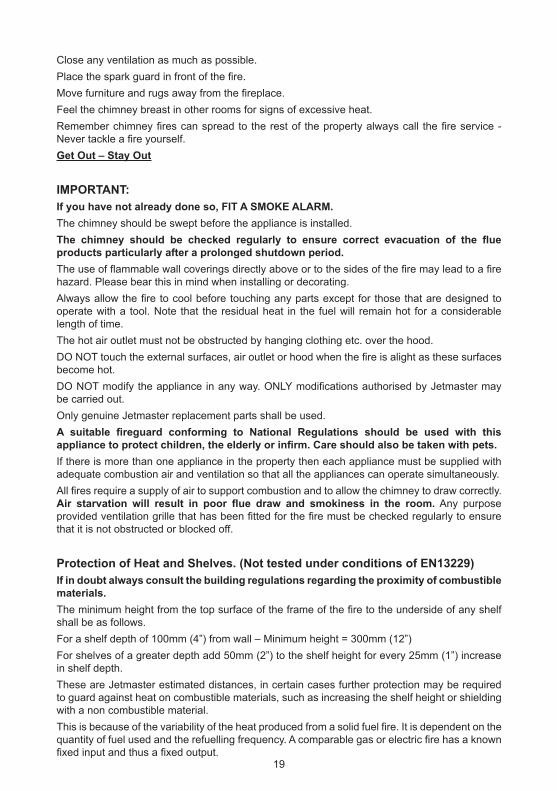
Protection of Heat and Shelves. (Not tested under conditions of EN13229)
If in doubt always consult the building regulations regarding the proximity of combustible
materials.
The minimum height from the top surface of the frame of the fire to the underside of any shelf
shall be as follows.
For a shelf depth of 100mm (4”) from wall – Minimum height = 300mm (12”)
For shelves of a greater depth add 50mm (2”) to the shelf height for every 25mm (1”) increase
in shelf depth.
These are Jetmaster estimated distances, in certain cases further protection may be required
to guard against heat on combustible materials, such as increasing the shelf height or shielding
with a non combustible material.
This is because of the variability of the heat produced from a solid fuel fire. It is dependent on the
quantity of fuel used and the refuelling frequency. A comparable gas or electric fire has a known
fixed input and thus a fixed output.19
Operating InstructionsStandard, Universal, Low and Extra Fires
Lighting after Installation
A Jetmaster should not be lit until all cement and plasterwork is completely dry and cured. As a
basic guide the installer should
a. Allow a 7-day drying time if the house has other forms of heating.
b. Allow at least 14 days if the installation is in a new or unoccupied property, or is fitted into
a completely new chimney breast.
Wood Burning Trays and Basket Grates
Jetmaster fires may be used to burn a variety of fuels. Fuels must not be burned directly in the
firebox. A range of wood burning trays, basket grates or gas burners are available to ensure that
each fuel is burned in the most effective way. Make sure that you have the right accessories to
get the best out of your fuel and your fire.
Wood Burning Tray
Use the wood burning tray when burning wood alone. (Solid mineral fuel or smokeless fuel
cannot be burned in the wood tray).
Allow the ash to build up to about 1” (25mm) deep in the wood burning tray to ensure even and
efficient burning. A new wood burning tray should always be started with some ash or sand in
its base
Ash Removal Ash should be allowed to build up in the tray and after a few weeks a hard lump
of ash will form under the hottest part of the fire. This should be left alone. It is desirable to clean
out a few small shovels full of the surplus light ash from the front and sides every 2-3 weeks.
(This may be more frequent if burning heavily). If this is done when there are some glowing
embers and with the throat restrictor open, any dust stirred up will be sucked up the chimney.
Keep the back and side air passages clear at all times.
When removing the tray and replacing always ensure that the tray is fitted the correct way
around. The tray should be fitted with the centre foot of the tray towards the rear of the firebox.
See Fitting the Wood Tray and Log Retainer in the Installation section of this booklet.
Lighting with Wood Burning Tray
When lighting the fire, the throat restrictor should be opened fully by pulling the operating lever
foreword. The fire may be lit using proprietary firelighters with kindling wood. Once this has
established slightly larger pieces may be added until the fire has a hold. At this point split logs or
whole logs may be added. The right technique comes with a little experience, and varies with the
type of fuel being burnt. See sections on Use of the Throat Restrictor and Fuels below.
Basket Grates
Use the basket grate for burning solid mineral fuels and smokeless fuels.
Wood can be burned in the basket grate but will burn away quickly and therefore is less
effective.
Ash Removal The removable ash pan simply slides out from under the grate for easy emptying.
Do not allow ash to build up in the ash pan until the grate bars are covered as this seriously
reduces the life of the grate. See Fitting the Basket in the Installation section of this booklet.
20

Lighting with Basket Grate
When lighting the fire, the throat restrictor should be opened fully by pulling the operating lever
foreword. When using solid mineral fuel or smokeless fuel place the fuel around the edge of the
basket forming a circle or two circles. Leave a well in the centre of each circle. Start the fire in
this well using proprietary firelighters and or kindling wood. Then gradually bring the fuel in over
the fire lighters/kindling. See sections on Use of the Throat Restrictor and Fuels below.
Use of the Throat Restrictor
The throat restrictor serves two purposes. It reduces the amount of air drawn up the chimney to
the minimum necessary to keep the fire burning well and to carry away the smoke. It also has
an effect upon the burning rate of the fire. The degree of control exercised by the throat restrictor
is dependent on the draw of the chimney.
When lighting the fire, the throat restrictor should be opened fully by pulling the operating lever
foreword. Once the fire is established, the operating lever may be pushed back to a position
where the throat restrictor is as far closed as possible while maintaining smoke or fume
clearance. Whenever fuel is added to the fire, the throat restrictor should once again be opened
fully until the fuel is well alight.
When operating the fire on a weak flue (as in some bungalows with relatively short chimneys)
the optimum position of the throat restrictor may be half open or more. With flues of greater
efficiency or taller chimneys, smoke clearance may be possible with the restrictor almost
completely closed. Note that in the latter case, a small throat area is left open to guarantee
chimney ventilation.
Damping down over long periods (overnight with logs on the large models), the fire should be
allowed to die down before banking up the fuel and closing the throat restrictor to the minimum
while maintaining smoke clearance. Banking up and closing the restrictor on a hot fire will cause
the fire to roar away, overheat and burn out quickly. The right technique comes with a little
experience, and varies with the fuel being burnt.
Seasonal Use
In the summer months or at times when the fire is not being used then the throat restrictor may
be closed to eliminate draughts and to minimise the air loss from the room.
Fuels
The table below shows the recommended fuel sizes, weights and refuel interval to achieve the
outputs given on pages 1 & 2 in accordance with EN13229: 2001
21
FUEL DATA STANDARD UNIVERSAL LOW EXTRA
MODEL 16 18 500 600 700 500 600 700 700 850 1050
WOOD TRAY
WOOD SIZE
Length & Diameter mm
200 Lth
75
200 Lth
75
200 Lth
75
200 Lth
75X
200 Lth
75 E
200 Lth
75 EX X X X
MAXIMUM REFUEL
WEIGHT Kg 2.5
2.9
E
4.1
E5.0 X
3.4
E
4.1
EX X X X
MINIMUM REFUEL
INTERVALHr 1
1
E
0.75
E0.5 X
0.75
E
0.5
EX X X X
BASKET GRATE
SMOKELESS FUEL
MAXIMUM REFUEL
WEIGHT Kg 2.5 X X X X X X X X X X
MINIMUM REFUEL
INTERVALHr 2 X X X X X X X X X X
BASKET GRATE
WOOD
MAXIMUM REFUEL
WEIGHT Kg 2.0 X X 2.7 X X X X X X X
MINIMUM REFUEL
INTERVALHr 0.3 X X 0.2 X X X X X X X
Note:- Data was derived using the following fuels, WOOD:- Beech, Birch, Hornbeam. SMOKELESS FUEL:- Homefi re. In accordance with EN13229:
2001. E = Jetmaster Figures

Recommended Fuel Types
1. Solid Mineral Fuels and Smokeless Fuels
Solid mineral fuels and open fire smokeless fuels may be burned in basket grates or in the
controlled burning grates. Use smaller lumps and some slack when banking down for longer
periods of unattended burning. Grade 2 Housecoal is recommended more tarry coals will need
more frequent stoking.
Of the smokeless fuels, Coalite and Homefire are particularly suitable. Anthracite, closed stove
or furnace fuels and petroleum based solid fuels should not be used in Jetmaster open fires.
2. Wood
Wood has about half the calorific value of coal, on a weight for weight basis. “Green” wood has
a high moisture content, which makes it difficult to burn, and reduces net heat output.
Buying a load of green firewood means you may have been buying as much water as you are
wood. When wood is burned, the water content is converted into steam. The large amount of
heat necessary to do this accounts for the reduction in useful heat. Air-drying, or seasoning,
reduces moisture content, thus making it easier to burn. Where green wood must be burned,
first build to a strong heat to ensure that enough excess heat is produced to dispose of the
moisture.
The readiness of wood to burn depends on the density and the size of each piece. Denser
hardwoods are generally better than softwoods such as pine, which when dry burn fast and split.
A split log will catch and burn better than a full round log. Only well seasoned wood should be
used. This also helps to burn off more of the tars, and to reduce the build up of tar deposits.
The fire burning rate can thus be controlled by the amount of fuel that is used the size of fuel
and the refuelling interval. Kindling wood will burn fast, split logs at a medium rate and whole
logs a little slower. So by mixing the sizes that are burnt and used in conjunction with the throat
restrictor the fire rate of burn and hence output can be controlled.
Any of the dense hardwoods are recommended such as:- Birch, Beech, Hornbeam, Oak, Ash,
Elm and numerous others not mentioned.
3. Peat (Not tested under conditions of EN13229)
Burns gently and should be slightly damp. A mixture of dry wood with the peat is particularly
effective in the wood-burning tray. In basket grates, mix with solid fuel. Peat should NOT be
used in controlled draught grates
4. Gas (Not tested under conditions of EN13229)
Some models are suitable for use with gas fuel effect inserts.
Low models and some older versions of the wood and coal convector box are not suitable for
gas conversions.
If a Jetmaster gas conversion kit is ever fitted in the firebox the damper or throat restrictor should
be removed. If removal is not possible, it must be permanently secured in the open position.
This must be in line with the Gas safety (Installation & Use) Regulations 1998.
Fire Screens
Lighted fires should always be left with a fire screen fitted, even if you only leave the room for a
few minutes. Every Jetmaster is supplied with a fire screen, which clips to the fire.
The fire screen will become hot and care should be taken when removing the fire screen from
an operational fire, as the fire screen handles may be hot.
The feet and base of the fire screen may get hot and could burn carpets and any combustible
floor covering. Always ensure that the fire screen is stood on a non-combustible surface (The
hearth).
22

Servicing Instructions
IMPORTANT –
ALLOW THE FIRE TO COOL BEFORE COMMENCING SERVICING OR
CLEANING
Servicing
To ensure safe, efficient operation of the appliance, it is necessary to carry out routine servicing
at regular intervals.
The frequency of servicing will depend on the particular installation conditions and the frequency
of use.
We recommend that flues should be swept at least twice a year, during the heating season.
More frequent sweeping may be necessary where fires are burned throughout the year or where
low grade wood or bituminous coal are used as fuels. Fires are provided with removable throat
restrictors to facilitate chimney sweeping and for the removal of soot from the top of the unit. A
small boss flue brush head that will fit to standard rods may be required for the smaller fires.
Where an external soot door is fitted the chimney can be swept from the outside. The throat
restrictor flap can then be closed during sweeping and the soot removed by vacuum (from
above).
Besides chimney sweeping any internal flueways should also be cleaned. Ensure that any soot
that has fallen on to the top of the unit is removed.
A check on the seal between the fire and the fireplace opening and hearth should be carried
out.
Remove and clean the throat restrictor. Replace and ensure correct operation and adjustment.
Finally carry out a smoke draw test as described in Commissioning Section or to the HETAS
recommended requirements.
Removal and Replacement of Throat Restrictors
1. Remove basket grate of wood burning tray with any log retainer.
2. Remove the two nuts securing the throat restrictor friction bar on the left sidewall of the
fire.
Care should be taken when removing these nuts so that they do not damage the
thread or shear the studs. Ideally they should be soaked in release fluid before
removing.
3. Move the throat restrictor to the right hand side and unhook from there by moving it away
from you until it drops down. Pull towards you and lower it out of the front of the fire.
4. Reassemble, by reversing the above operation and then replace the friction bar and its
securing nuts. Tighten the nuts and check for satisfactory operation, adjusting where
necessary.
Cleaning and Maintenance
The visible front parts of the fire unit and the front edge of the wood tray and ash pan should be
repainted with heat resistant black paint. These parts can be repainted every 1 or 2 years as
23
required but generally dusting with a soft brush should keep the fire looking good. The interior
of the firebox and the grate should not be painted.
To maintain the finish on Decorative Surrounds wipe with a soft damp cloth only. Do not use
abrasive cleaners, polish or solvents as these can damage the surface finish
Jetmasters Guarantees
Jetmaster Fires Ltd Provide TWO Guarantees for All Gas, Wood and
Coal Fires
Gas FiresAn Automatic One Year Guarantee on all products.
Excludes: -
Batteries in Comfort Control (CC) and Remote Control (RC) Systems.
Fireplace components pertaining to the installation or costs associated with replacement
components, parts and installation are not covered by this Guarantee.
A Registerable Two Year Guarantee on Gas Fires if you register the Guarantee
Registration Card within one month of purchase
Wood and Coal FiresAn Automatic Two Year Guarantee on all products.
Excludes: -
Bottom grates, for which replacement parts can be purchased from Jetmaster.
Firebox damper assembly including friction bar, nuts, studs and bolts.
The Guarantee does not cover rust.
Fireplace components pertaining to the installation or costs associated with replacement
components, parts and installation are not covered by this Guarantee.
A Registerable Ten Year Guarantee on Standard, Universal, Low and Extra fires
(firebox only), if you register the Guarantee Registration Card within one month
of purchase
The full terms and conditions are set out below and/or over the page.
Two Year Guarantee (Registerable on Gas Fires)Jetmaster Fires Ltd (“Jetmaster”) is so confident in the quality and design of its products that it
provides a Two Year Guarantee automatically on all Wood and Coal Products against defects in
materials and workmanship. Valid from date of original purchase.
Registerable on Gas Products.
This Guarantee is only effective on gas products if the Guarantee Registration Card has been
received fully completed at Jetmasters offices within one month of the date of purchase of the
fire.
Gas
Excludes: -
Oxypilots, polished parts, paintwork, batteries, ceramic parts and coals.
24

The Guarantee does not cover rust.
Fireplace components pertaining to the installation or costs associated with replacement
components, parts and installation are not covered by this Guarantee.
Wood and Coal
Excludes: -
Bottom grates, for which replacement parts can be purchased from Jetmaster.
Firebox damper assembly including friction bar, nuts, studs and bolts.
The Guarantee does not cover rust.
Fireplace components pertaining to the installation or costs associated with replacement
components, parts and installation are not covered by this Guarantee.
Ten Year Guarantee Wood and Coal (Registerable)Jetmaster Fires Ltd (“Jetmaster”) is so confident in the quality and design of its fireplace units
that it provides a Ten Year Guarantee against defects in materials and workmanship in its
Standard, Universal, Low and Extra Fires (Firebox Only). Valid from date of original purchase.
This guarantee is only effective on wood and coal products if the Guarantee Registration Card
has been received fully completed at Jetmaster offices within one month of the date of purchase
of the fire.
Excludes: -
Baskets, bottom grates, ash pans, wood burning trays, log retainers, pokers, firescreens, water
heating attachments, firebox damper assembly including friction bar, nuts, studs, bolts and other
accessories including fireplace components pertaining to the installation or costs associated
with replacement components, parts and installation are not covered by this Guarantee.
The Guarantee does not cover rust.
Terms and ConditionsThe Guarantees are only effective where:-
1. The fire/product has been purchased from an Appointed Distributor of Jetmaster.
2. The Appointed Distributor of Jetmaster has first investigated the complaint.
3. The installation and operation of the fire is, in the opinion of the Appointed Distributor
and of Jetmaster in accordance with those Jetmaster “Installation Instructions” and
“Installation and Operating Instructions” current at the time of purchase.
4. Only Jetmaster authorised accessories are and have been used and coal or coal-
based bituminous and smokeless fuels, wood, and gas are burned in accordance with
the Jetmaster “Installation and Operating Instructions” at all times.
5. No modifications have been made to the fire and accessories without written authority
from Jetmaster.
6. On gas the appliance is serviced annually by a CORGI registered engineer.
7. Jetmaster will not be responsible for defective operation of the appliance resulting
from:
a) Down drafts or spillage caused by environmental conditions such as nearby
trees, buildings, rooftops, hills or mountains.
b) Inadequate ventilation or negative air pressure caused by mechanical
systems such as fans, cookers, extraction hoods, clothes dryers etc.
c) Installations operating in atmospheres contaminated by damaging
chemicals.
d) Installations that are subjected to prolonged periods of dampness or
25

condensation.
e) Any damage to the combustion chamber, heat exchanger or other
components due to water or weather damage which is the result of but not
limited to, improper chimney/venting installation.
f) Parts (including ceramic parts) fitted to the appliance other than supplied by
Jetmaster.
8. This Guarantee is limited to the repair or replacement of parts found to be defective in
material or workmanship after confirmation of the defect by Jetmaster, provided that
such parts have been subjected to normal conditions of operation.
9. Jetmasters liability shall be limited to the cost of the unexpired portion of the Guarantee
period.
10. This Guarantee is valid from the date of the original purchase.
11. All other Guarantees expressed or implied with respect to the product, it’s components
and accessories or any obligations/liabilities on the part of Jetmaster are hereby
expressly excluded.
12. Jetmaster will not be responsible for any incident, indirect or consequential damages,
except as provided by law.
13. Jetmaster neither assumes, nor authorises any third party to assume, on it’s behalf,
any other liabilities with respect to the sale of this “Jetmaster” fire.
The Guarantees Do Not Cover:-
Any alteration, wilful abuse, accidental damage or misuse of the product.
Routine maintenance/Service.
Parts that need to be replaced on a routine basis e.g. Bottom grates, coals and ceramic fibre
components, batteries, oxypilots after one year, etc. and cosmetic blemishes to polished metal
surfaces after one year.
Once satisfied that the above conditions have been complied with and provided that evidence
of the date of purchase from an Appointed Distributor within the two years, or in the case of
the wood and coal convector fireboxes ten years, can be produced by the then owner of the
product, and the defect is notified in writing to the Appointed Distributor within two years, or in
the case of the wood and coal convector fireboxes within ten years of the purchase date of the
product, then, Jetmaster at its discretion, will arrange with the Appointed Distributor either to
replace or repair the faulty product.
Statutory RightsThese Guarantees are additional to and do not in any way affect the statutory rights of the
buyer.
ComplaintsWhen making a complaint under either of the above Guarantees, the owner should not
contact Jetmaster direct unless he is unable to contact the Appointed Distributor.
SpecificationsWhilst every endeavour is made to supply the goods illustrated in Jetmasters brochures, any
photographs, descriptions, specifications, illustrations or advertising matter represent generally
Jetmasters goods offered, but shall not constitute a sale by description.
Jetmaster reserves the right to supply similar but not identical goods to those illustrated
provided that the overall construction and design has not been altered fundamentally. Further,
26

any deviation shall not be taken to vitiate any contract and shall not form the grounds for any
claim against Jetmaster.
Trademark“Jetmaster” is the United Kingdom Registered Trademark of Jetmaster Fires Limited No
B809215
Jetmasters policy is one of continual advance in the quality of our products. Thus strict
accuracy of illustrations and descriptions cannot be guaranteed. We reserve the right to
change this specification without notice. Whilst we and our distributors will endeavour to
ensure that you have the most up-to-date information, we urge you to check the date at the
end of this publication, and, if it is more than six months old, to check with your Distributor to
ensure it has not been superseded. The statutory rights of the consumer are not affected.
Contact DetailsJetmaster Fires Ltd,
Unit 2, Peacock Trading Estate,
Goodwood Road,
Eastleigh,
Hampshire, SO50 4NT
Telephone: 02380 629513Fax: 02380 629567Email: [email protected]: www.jetmaster.co.uk
27


Jetmaster Fires Ltd,
Unit 2 Peacock Trading Estate, Goodwood Road,
Eastleigh, Hampshire SO50 4NT
Telephone and Messages: 02380 629513Fax: 02380 629567
Sales: [email protected] Web: www.jetmaster.co.uk Info: [email protected] Technical: [email protected]


![Index [rd.springer.com]978-3-662-06267-8/1.pdf · alAT• biological characteristics of 21 -, clinical abnormalities 21 ... -tumor 366 amyloidosis 201, 218, 356, 365 -, intestinal](https://img.dokumen.tips/doc/110x75/5ccfd0b888c993b6568d45c4/index-rd-978-3-662-06267-81pdf-alat-biological-characteristics-of-21.jpg)