Embed Size (px)
Citation preview

5
28237
JET PUMP

5-0 - PUMP UNIT 90-852396 MAY 1996
Table Of ContentsPage
General Information 5-1. . . . . . . . . . . . . . . . . . . . . . .
Principles Of Operation 5-1. . . . . . . . . . . . . . . . . . Special Tools 5-2. . . . . . . . . . . . . . . . . . . . . . . . . . .
Drive Housing Components 5-4. . . . . . . . . . . . . . . . .
Pinion & Impeller Shaft 5-6. . . . . . . . . . . . . . . . . . . . .
Nozzle/Rudder Components 5-8. . . . . . . . . . . . . . . .
Servicing Stator, Impeller And Wear Ring 5-10. . . .
Disassembly 5-10. . . . . . . . . . . . . . . . . . . . . . . . . . Removing Reverse Gate, Rudder AndNozzle As An Assembly 5-10. . . . . . . . . . . . . . Stator Removal 5-10. . . . . . . . . . . . . . . . . . . . . Impeller Removal 5-11. . . . . . . . . . . . . . . . . . .
Inspecting Components 5-11. . . . . . . . . . . . . . . . Installing Impeller 5-11. . . . . . . . . . . . . . . . . . . . . .
Removing Jet Drive From Boat 5-12. . . . . . . . . . . . .
Drive Housing Disassembly And Reassembly 5-13
Pinion Shaft Removal 5-13. . . . . . . . . . . . . . . . . . Impeller Shaft Removal 5-14. . . . . . . . . . . . . . . . . Shimming Procedures 5-17. . . . . . . . . . . . . . . . . .

90-852396 MAY 1996 PUMP UNIT - 5-1
General InformationNOTE: Due to running changes, some illustrationsmay not be exactly the same as your drive unit. Ser-vice procedures remain the same unless otherwisenoted.
Principles of OperationThe jet pump operates by drawing water into ahousing forward of the impeller. The water is pres-surized within the specially designed housing andthen directed to the rear to provide thrust and mo-tion.
a
b
c
54898
a - Forward Motionb - Water Thrust
c - Reverse Gate(Shown In the ForwardPosition)
The jet pump is equipped with a steerable nozzle(rudder) at the aft end of the pump housing that di-rects the thrust of water. The jet of water can be di-rected right or left when the operator turns the steer-ing wheel in the respective direction. When the op-erator turns the steering wheel to the right, for exam-ple, the nozzle turns to the right and the jet forcefrom the nozzle pushes the stern of the boat to theleft causing the bow of the boat to turn right.
Forward and reverse drive and the neutral positionare achieved by the position of a reverse gate lo-cated just aft of the nozzle. Forward drive has thereverse gate clearing the nozzle to allow all thethrust to be directed straight back. Reverse drivehas the reverse gate covering the entire openingenough to divert the thrust forward. Neutral positionhas the reverse gate covering 75 percent of thenozzle to direct the water stream forward and down-ward, as well as backward. The shift position is con-trolled at the control box in the boat.
a54896
a - Reverse Gate (Shown In the Reverse Position)

5-2 - PUMP UNIT 90-852396 MAY 1996
Special ToolsJet Pump Tool Kit 91-809957A1
Description Part Number
a Pre-Load KitImpeller Shaft
91-824871A2
b Thread Extender Kitused w/ Backlash Kit
91-824869A1
c Seal ProtectorImpeller Shaft
91-850233
d Impeller Shaft Wrench 91-832093A1
e Impeller Nut Socket 91-850297
f Pinion Gear Location Tool 91-831897
g Bearing Installerpress ball bearing andseals into pinion shafthousing
91-832016
h Bushing Installerstator bushings & seal
91-850831
i Seal Installerimpeller shaft seals indrive housing
91-832019
j Bearing Installerimpeller shaft ballbearing in drive housing
91-832017
k Bearing Cup Installerpinion shaft housing anddrive housing front cover
91-832018
l Handle Driver 91-824892
Backlash Indicator Flaguse MCII line
91-53459
Dial Indicator Kit 91-58222A1
Dial Indicator Adapter Kit 91-83155
Slide Hammer 91-34569A1
Bearing Puller Kit 91-83165M
Retaining Ring Pliers 91-25081
Lubricants/Adhesives Part Number
Loctite, #271 92-809820
Loctite, #242 Obtain Locally
Perfect Seal 92-34227--1
2-4-C Lubricant w/ Teflon 92-825407A12
Special Lube 101 92-13872A1
Hi Performance Gear Lube 92-19007A24
a b
d
e
f gh
i j
l
k
c

90-852396 MAY 1996 PUMP UNIT - 5-3
NOTES:

5-4 - PUMP UNIT 90-852396 MAY 1996
DRIVE HOUSING COMPONENTS
12
8
56
7
3
12
13
15
16
19
17
23
2021
30
22
24 26
2728
18
31
29
4
910
4
11
5
5
67
8
18
14
25
66 Loctite “242” (Purchase Locally)
85 RTV Silicone Sealer (92-809825)
85
66
66
90-852396 MAY 1996 PUMP UNIT - 5-5
DRIVE HOUSING COMPONENTSREF. TORQUEREF.NO. QTY. DESCRIPTION lb. in. lb. ft. N·m
1 1 HOUSING ASSY-Drive (Basic) (Painted)
2 1 PIN-Dowel
3 1 FITTING-Syphon Drain Hose
4 2 FOAM-Exhaust Deflector w/ 3-M #874 Adhesive
5 6 STUD (M10 x 76) w/ 271 Loctite
6 12 NUT (M10) 35 47
7 4 STUD (M10 x 55) w/ 271 Loctite
8 2 SEAL-Oil
9 1 BEARING-Ball
10 1 RING-Snap
11 1 GASKET-Drive Housing
12 1 COVER ASSY W/Gaskets-Drive Housing (Painted)
13 2 STUD (M10 x 66)
14 1 O RING
15 1 GASKET-Cover To Adapter Plate
16 AR GROMMET-Pump Mount (.250)AR GROMMET-Pump Mount (.375)
AR GROMMET-Pump Mount (.500)17 1 NUT (M8)
18 2 BAFFLE ASSEMBLY-Exhaust
19 1 SCREW (M8 x 240))
20 2 SCREW KIT
21 2 WASHER-Sealing
22 1 SEAL-Ride Plate, Self Locking
23 1 SCREEN-Inlet (Painted)
24 2 SCREW (M8 x 16) w/ Loctite 242 200 23
25 2 SCREW With Nylon Patch (M6 x 20) w/ Loctite 242 75 8.5
26 1 PLATE-Trim
27 2 NUT (M8)
28 2 WASHER
29 2 SCREW (M8 x 35) 35 47
30 1 RIDE PLATE KIT (Painted)
31 16 SCREW With Nylon Patch (M6 x 13) w/ Loctite 242 75 8.5

5-6 - PUMP UNIT 90-852396 MAY 1996
PINION & IMPELLER SHAFT
1
2
4
3
5
7
6
8
9
10
11
1213
1415
16
17
18
4
Special Lubricant 101 (92-13872A1)108
108
7
7 Loctite “271” (92-809820)
95 2-4-C w/Teflon (92-825407A12)
95
95
90-852396 MAY 1996 PUMP UNIT - 5-7
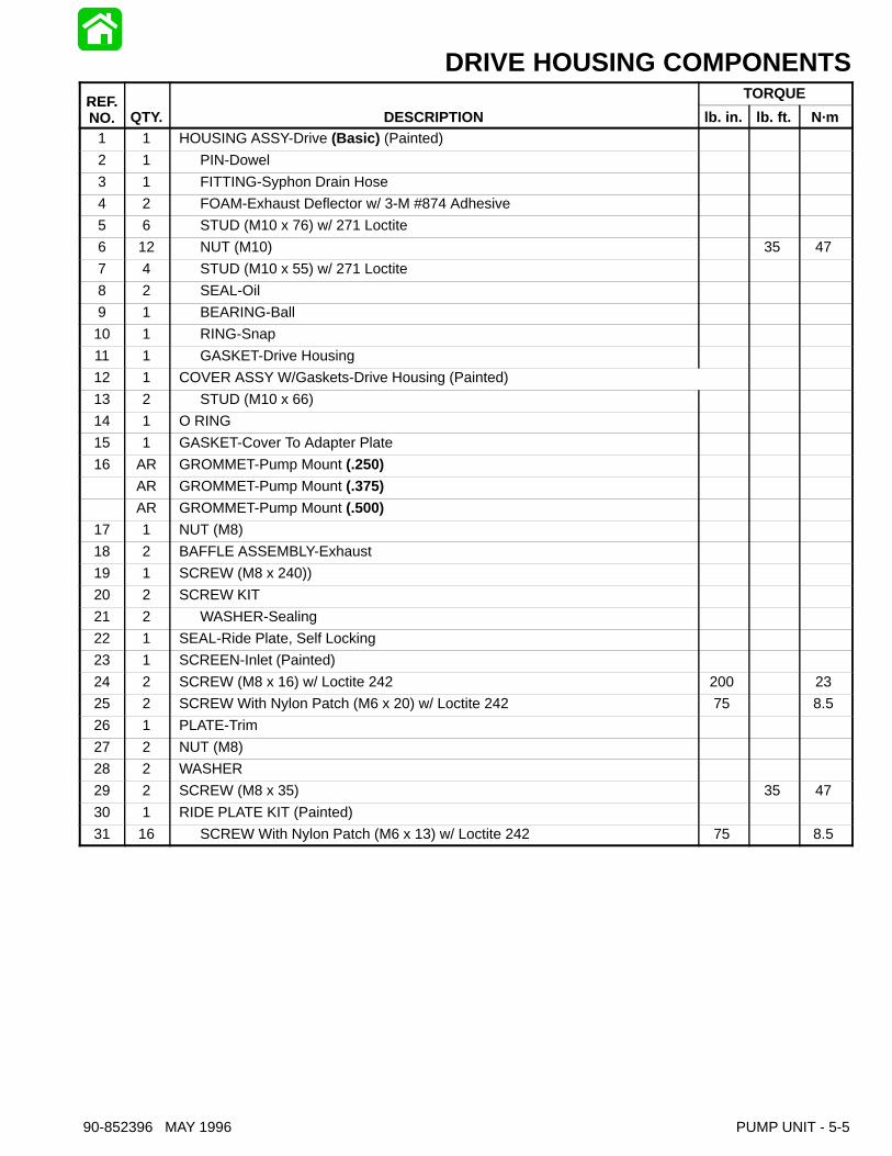
PINION & IMPELLER SHAFTREF. TORQUEREF.NO. QTY. DESCRIPTION lb. in. lb. ft. N·m
1 1 RING-Rubber
2 4 SCREW (M8 x 25) 180 20.3
3 1 HOUSING ASSEMBLY-Pinion Shaft (Painted)
4 2 SEAL-Pinion Shaft Housing
5 1 BEARING-Ball
6 1 BEARING SET
7 1 O RING
AR SHIM (Red) (.002)
AR SHIM (Beige) (.004)
8AR SHIM (Blue) (.005)
8AR SHIM (Frost/Clear) (.0075)
AR SHIM (Brown) (.010)
AR SHIM (Yellow) (.020)
9 1 GEAR/SHAFT ASSEMBLY-Pinion
10 1 SHAFT-Impeller
11 1 GEAR-Impeller Shaft
12 1 WASHER
13 1 NUT (M14) 90 122
AR SHIM (Red) (.002)
AR SHIM (Beige) (.004)
14AR SHIM (Blue) (.005)
14AR SHIM (Frost/Clear) (.0075)
AR SHIM (Brown) (.010)
AR SHIM (Yellow) (.020)
15 1 COVER ASSEMBLY-Impeller Shaft (Painted)
16 1 BEARING SET
17 1 O RING
18 4 SCREW (M8 x 25) 180 20.3

5-8 - PUMP UNIT 90-852396 MAY 1996
NOZZLE/RUDDER COMPONENTS
1
3940
34
37
36
35 27
31
32
28
2930
26
23
2425
22
21
20
19
11
12
8
14
10
5
9
16
1817
7
13
38
4
2
33
15
3
6
910
12
20
21
22
31
7 Loctite “271” (92-809820)
7
7
7
7
7

90-852396 MAY 1996 PUMP UNIT - 5-9
NOZZLE/RUDDER COMPONENTSREF. TORQUEREF.NO. QTY. DESCRIPTION lb. in. lb. ft. N·m
1 1 PIN-Clevis
2 1 CONNECTOR-Cable End
3 1 WASHER
4 1 PIN-Cotter
5 1 GATE ASSEMBLY (Painted)
6 1 SCREW (M6 x 13)
7 1 ANODE
8 1 LOCKWASHER (.250 Internal)
9 2 BUSHING-Pivot
10 4 BOLT-Pivot w/ Loctite 271 50 68
11 1 RUDDER KIT (Painted)
12 2 BUSHING-Pivot
13 1 LOCKWASHER (.250 Internal)
14 1 ANODE
15 1 SCREW (M6 x 13)
16 2 SCREW (M10 x 45) 35 47
17 1 ANODE
18 2 LOCKWASHER (.437 External)
19 2 SCREW (M10 x 35) 35 47
20 2 SCREW (M8 x 30) 120 13.5
21 2 WASHER
22 2 STOP-Reverse Gate
23 1 NOZZLE ASSY-W/Pivot Bushings (Painted)
24 1 FITTING-Nozzle
25 1 HOSE-Syphon (12.00 In.)
26 4 SCREW (M10 x 150) 35 47
27 1 STATOR ASSEMBLY (Painted)
28 1 PLUG-Pipe
29 1 SCREW KIT 50 5.6
30 1 WASHER-Sealing
31 2 BUSHING-Stator Rear
32 1 SEAL
33 2 WASHER-Tab
34 1 RING KIT-Wear (Painted)
35 1 PLUG-Pipe (.750-14)
36 1 O RING
37 1 O RING
38 1 IMPELLER KIT-SS-5 Blade
39 1 TAB WASHER-Impeller Shaft
40 1 NUT-Impeller Shaft 150 203

5-10 - PUMP UNIT 90-852396 MAY 1996
Servicing Stator, Impellerand Wear Ring
Disassembly1. Disconnect spark plug leads from spark plugs.
2. Disconnect shift and steering cables at Reversegate and Rudder.
54896
a b
a - Shift Cableb - Steering Cable
IMPORTANT: This procedure lists the dissas-sembly of external pump components. If servic-ing a specific component, follow the procedure inthat section.
REMOVING REVERSE GATE, RUDDER ANDNOZZLE AS AN ASSEMBLY
3. Remove four screws securing nozzle to stator.Remove reverse gate/rudder/nozzle assembly.
54579c
c - Screws (4)
STATOR REMOVAL
4. Remove two screws securing trim plate to rideplate and wear ring.
28252ab
a - Screws (2) to Trim Plate & Wear Ringb - Trim Plate
5. Remove four screws securing stator assembly todrive housing. Remove stator assembly.
28253
c
c - Stator
6. Drain stator by tilting stator forward and allowingthe oil to drain over the impeller shaft seals.Complete oil draining by removing stator fillscrew and pour the remaining oil out the fill screwhole.

90-852396 MAY 1996 PUMP UNIT - 5-11
IMPELLER REMOVAL
7. If removed, install wear ring to support impellerand shaft during impeller removal.
8. Remove inlet screen on bottom of drive housingto allow access to machined flats on impellershaft. If using Special Tool 91-832093A1 to holdimpeller shaft, inlet screen does not need to beremoved.
9. Straighten tabs on impeller tab washer.
10. While holding impeller shaft, remove impeller nutusing Special Tool 91-850297. Impeller nut is astandard right hand thread. Remove impeller.
28252a
b
a - Special Tool 91-850297b - Special Tool 91-832093A1
11. Remove wear ring.
Inspecting Components1. Inspect wear ring for excessive scoring and/or
grooves. Replace wear ring if deep grooves arepresent or if severe scoring has taken place.
2. Ensure O-ring is in counterbore before installingwear ring to drive housing.
28255
c
dc - O-ringsd - Inspect Surface for Grooves/Scoring
3. Inspect seal in stator for wear/damage.
4. Inspect bellows on cables for wear.
5. Inspect anodes, replace as necessary.
6. Inspect pivot pins and bushings, replace as nec-essary. Torque on reverse gate and rudder pivotpins is 50 lb. ft. (68 N·m). Use Loctite 271 onthreads.
7. Inspect impeller for cracks and damaged blades.
8. Inspect stator vanes for cracks and/or damage.
9. If replacement is required, remove stator seal us-ing Puller 91-83165M.
28256
10. Install new seal using Special Tool 91-850831.Smaller diameter seal lip faces out.
Installing Impeller1. Lubricate splines of impeller shaft with Special
Lube 101 (92-13872A1).
2. Install impeller, tab washer and nut on impellershaft. Locate bent tab in impeller slot. Torque im-peller nut to 150 lb. ft. (203 N·m). Bend one tabagainst flat on nut.
3. Install inlet screen. Apply Loctite 242 to threadsof screws and bolts. Torque the two 6 mm screwsto 75 lb. in. (8.5 N·m). Torque the two 8 mm boltsto 200 lb. in. (22.5 N·m).
4. Install wear ring and stator. Apply Perfect Seal tothreads of four bolts. Torque to 35 lb. ft. (47 N·m).

5-12 - PUMP UNIT 90-852396 MAY 1996
5. Remove stator fill screw with washer and fill sta-tor with High Performance Gear Lube(92-13783A24) until oil flows out fill hole (capac-ity is 19 fl. oz. / 550 cc). Install fill screw andwasher.
54894
a
a - Fill Screw
6. Apply Loctite 242 to screws (2) securing trimplate to the ride plate. Torque screws to 75 lb. in.(8.5 N·m).
a 28252b
a - Screws (2) to Trim Plate & Wear Ringb - Trim Plate
7. Install nozzle assembly and anode. Apply Loc-tite 271 to threads of screws. Torque all four (4)screws to 35 lb. ft. (47 N·m).
8. Attach shift and steering cables.
REFER TO SECTION 1D: SPORT JET INSTALLA-TION FOR SHIFT AND STEERING INSTALLATIONAND ADJUSTMENT.
Removing Jet Drive FromBoatREMOVE POWERHEAD AS OUTLINED IN SEC-TION 4.
1. Disconnect shift and steering cables from re-verse gate and rudder. Remove cable adaptorsand bellows assemblies. Loosen shift and steer-ing cables at wear ring.
54896
a b
a - Shift Cableb - Steering Cable
2. Loosen shift and steering cable thru hull fittings.
3. Support pump.
28257
WARNINGThe pump unit must be supported to prevent itfrom dropping through the opening when the re-maining fasteners are removed.
4. Remove remaining four nuts from drive housingcover. Remove drive housing cover and gasket.
54980
a
a - Nuts (4)
90-852396 MAY 1996 PUMP UNIT - 5-13
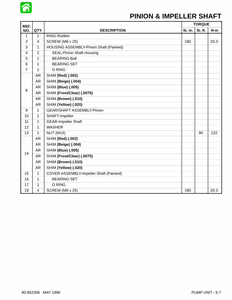
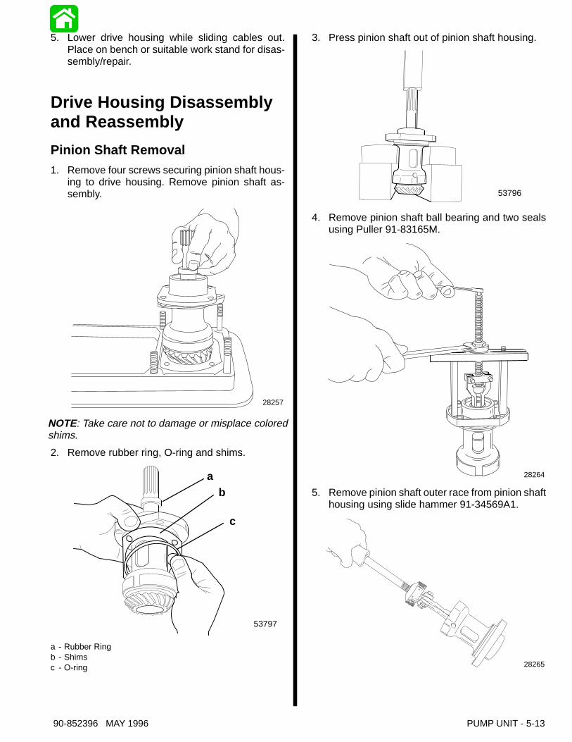
5. Lower drive housing while sliding cables out.Place on bench or suitable work stand for disas-sembly/repair.
Drive Housing Disassemblyand Reassembly
Pinion Shaft Removal1. Remove four screws securing pinion shaft hous-
ing to drive housing. Remove pinion shaft as-sembly.
28257
NOTE: Take care not to damage or misplace coloredshims.
2. Remove rubber ring, O-ring and shims.
53797
ab
c
a - Rubber Ringb - Shimsc - O-ring
3. Press pinion shaft out of pinion shaft housing.
53796
4. Remove pinion shaft ball bearing and two sealsusing Puller 91-83165M.
28264
5. Remove pinion shaft outer race from pinion shafthousing using slide hammer 91-34569A1.
28265

5-14 - PUMP UNIT 90-852396 MAY 1996
6. Press new outer race into pinion shaft housingusing mandrel 91-832018.
28264
7. Remove tapered roller bearing from pinion shaftusing universal puller plate 91-37241.
8. Press new tapered roller bearing onto pinionshaft using Special Tool 91-827983.
28265
9. Press new ball bearing into pinion shaft housingusing Special Tool 91-832016.
28266
10. Press pinion shaft into pinion housing.
28267
11. Press new seals into pinion shaft housing, oneat a time, using Special Tool 91-820552. Innerseal faces in, outer seal faces out.
28268
a
a - Special Tool 91-820552
Impeller Shaft Removal1. Remove Stator, Wear Ring and Impeller as de-
scribed in “Servicing Impeller”.
2. Remove stator fill screw, drain oil into a suitablecontainer.
3. Remove ride plate.

90-852396 MAY 1996 PUMP UNIT - 5-15
4. Remove four screws securing impeller shaft cov-er to drive housing. Remove cover.
28257
NOTE: Take care not to damage or misplace coloredshims.
28258
a
b
a - O-ringb - Shims
5. Remove nut and washer from end of impellershaft. Remove impeller shaft gear.
28259
6. Pull impeller shaft from drive housing.
28259
7. Remove bearing retaining ring from drive hous-ing.
28262
8. Remove bearing using Puller 91-83165M.
28263
9. Remove impeller shaft seals using Slide Ham-mer 91-34569A1.
5-16 - PUMP UNIT 90-852396 MAY 1996
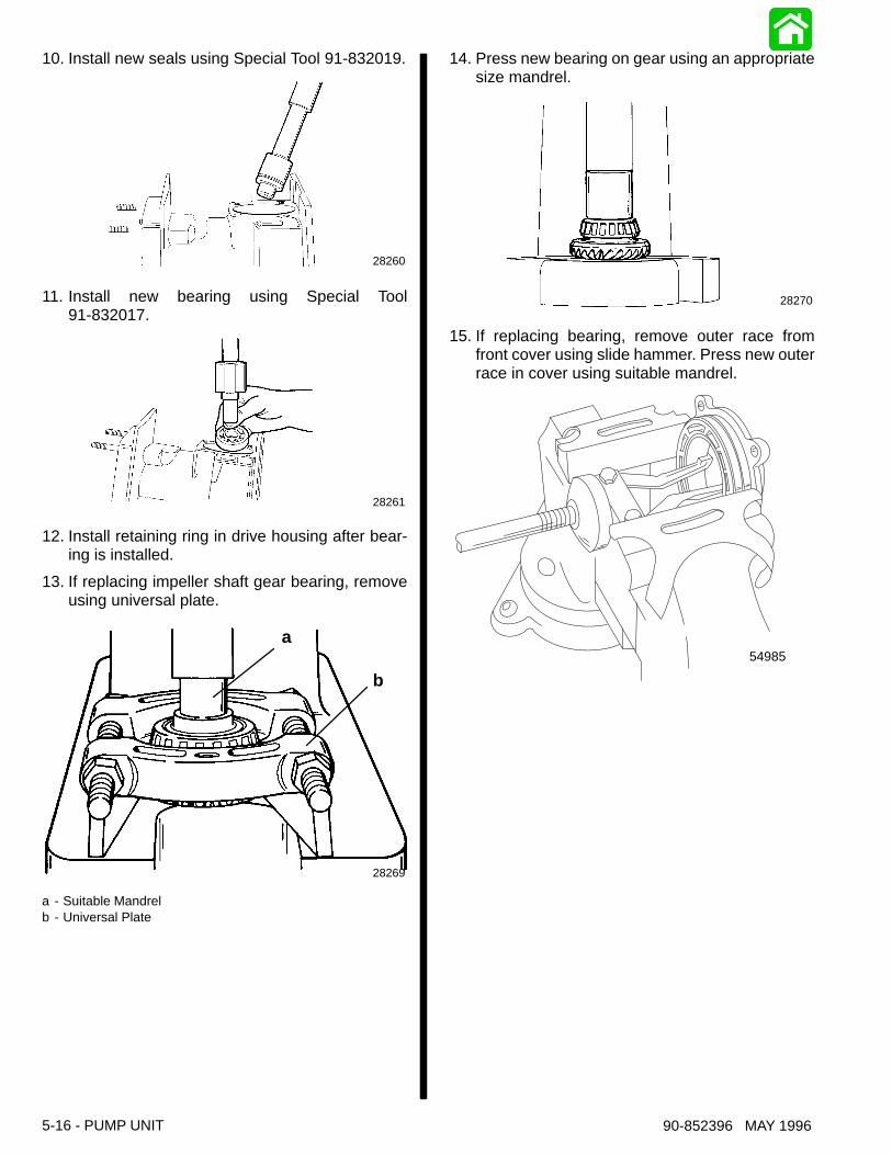
10. Install new seals using Special Tool 91-832019.
28260
11. Install new bearing using Special Tool91-832017.
28261
12. Install retaining ring in drive housing after bear-ing is installed.
13. If replacing impeller shaft gear bearing, removeusing universal plate.
28269
a
b
a - Suitable Mandrelb - Universal Plate
14. Press new bearing on gear using an appropriatesize mandrel.
28270
15. If replacing bearing, remove outer race fromfront cover using slide hammer. Press new outerrace in cover using suitable mandrel.
54985

90-852396 MAY 1996 PUMP UNIT - 5-17
Shimming ProceduresNOTE: Pinion gear shimming and backlash proce-dures must be preformed when any of the followingcomponents have been replaced:
a. Jet Drive Housing
b. Pinion Gear
c. Pinion Gear Bearing Assembly
d. Pinion Shaft Housing
e. Impeller Gear
f. Impeller Gear Bearing Assembly
g. Impeller Shaft Front Cover
NOTE: Shims are color coded to represent differentthicknesses. These color codes apply to both pinionhousing shims and impeller cover shims.
Red .002 in. (.05 mm)
Beige .004 in. (.10 mm)
Blue .005 in. (.127 mm)
Frost (Clear) .0075 in. (.19 mm)
Brown .010 in. (.25 mm)
Yellow .020 in. (.51 mm)
1. Install original shims on pinion shaft housing.Install O-ring on pinion shaft housing.
NOTE: If original shims are not available, start with.030 in. (.76 mm) shims (three brown colored shims).
2. Install pinion shaft assembly into drive housingbore. Torque screws to 180 lb. in. (20.3 N·m).
28271
3. Rotate pinion shaft ten revolutions to properlyseat roller bearings.
4. Insert Pinion Location Tool (Special Tool91-824890) in drive housing.
NOTE: Carefully inspect location tool to make sure itis seated in drive housing bearing.
5. Insert feeler gauge through hole in pinion loca-tion tool between gauging surface of tool andflats on bottom of pinion gear teeth.
IMPORTANT: The correct clearance is .025 inch(0.64 mm).
6. Use .025 inch (.064 mm) feeler gauge as a start-ing thickness. Adjust thickness of feeler gaugeuntil a slight drag is felt as gauge is drawn out be-tween gauging surface of tool and pinion gear.
NOTE: Once the thickness is determined, the differ-ence between feeler gauge thickness and .025 inch(0.64mm) required clearance must be either addedor subtracted from the total thickness of shims be-tween pinion shaft housing and drive housing.
• Remove the screws securing the pinion shafthousing assembly to the drive housing. Lift as-sembly out of the drive housing.
• Adjust shim thickness as required.
7. Install seal protector, Special Tool 91-850233,on impeller shaft. Install impeller shaft in drivehousing, then remove seal protector.
54986a
a - Seal Protector, Special Tool 91-850233
5-18 - PUMP UNIT 90-852396 MAY 1996
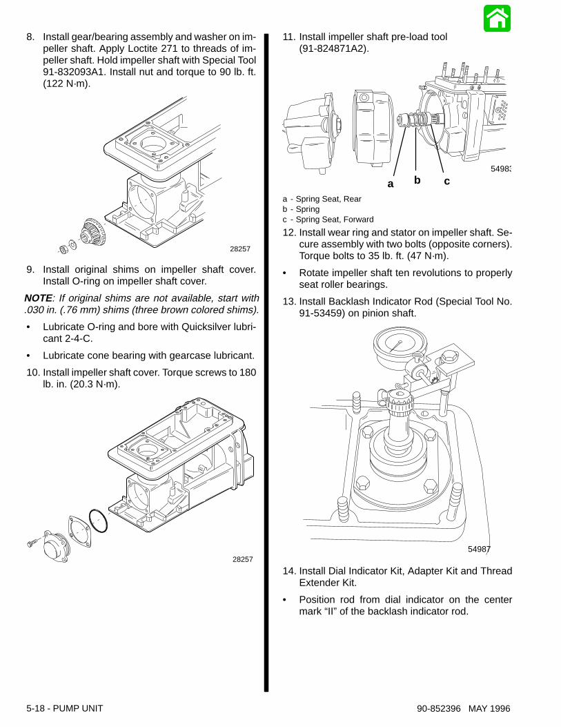
8. Install gear/bearing assembly and washer on im-peller shaft. Apply Loctite 271 to threads of im-peller shaft. Hold impeller shaft with Special Tool91-832093A1. Install nut and torque to 90 lb. ft.(122 N·m).
28257
9. Install original shims on impeller shaft cover.Install O-ring on impeller shaft cover.
NOTE: If original shims are not available, start with.030 in. (.76 mm) shims (three brown colored shims).
• Lubricate O-ring and bore with Quicksilver lubri-cant 2-4-C.
• Lubricate cone bearing with gearcase lubricant.
10. Install impeller shaft cover. Torque screws to 180lb. in. (20.3 N·m).
28257
11. Install impeller shaft pre-load tool(91-824871A2).
54983
a b c
a - Spring Seat, Rearb - Springc - Spring Seat, Forward
12. Install wear ring and stator on impeller shaft. Se-cure assembly with two bolts (opposite corners).Torque bolts to 35 lb. ft. (47 N·m).
• Rotate impeller shaft ten revolutions to properlyseat roller bearings.
13. Install Backlash Indicator Rod (Special Tool No.91-53459) on pinion shaft.
54987
14. Install Dial Indicator Kit, Adapter Kit and ThreadExtender Kit.
• Position rod from dial indicator on the centermark “II” of the backlash indicator rod.

90-852396 MAY 1996 PUMP UNIT - 5-19
15. Rotate pinion shaft back and forth lightly to con-tact gear teeth in each direction.
NOTE: Average total amount of reading of indicatorbacklash specification is .007 inch (.18 mm) to .009inch (.23 mm).
• If reading is less than minimum, add shims be-tween impeller cover and drive housing.
• If reading is more than maximum remove shimsbetween impeller cover and drive housing.
• Ratio of backlash reading to shims is 1:1.
16. Install impeller, wear ring and stator as outlinedin “Installing Impeller” in this section.
17. Apply RTV Sealant (92-809825) on rideplate.Install rideplate. DO NOT reuse screws. ApplyLoctite 242 to threads of new screws. Torque to75 lb. in. (8.5 N·m).
18. Install nozzle/reverse gate assembly and anode.Apply Loctite #271 to threads of screws. Torqueall four (4) screws to 35 lb. ft. (47 N·m).
19. Remove fill and vent screws from bottom of drivehousing. Fill drive housing with High Perfor-mance Gear Lube. Capacity is 27 oz. (825 cc).
28272
a
bc
a - Fill/Drain Screwb - Vent Screwc - RTV Sealant 92-809825
NOTE: To obtain correct oil level pump housing mustbe level and upright.
REFER TO SECTION 1D: SPORT JET INSTALLA-TION TO COMPLETE INSTALLATION OF DRIVEHOUSING, SHIFT AND STEERING CABLE INSTAL-LATION AND ADJUSTMENT.