Embed Size (px)
Citation preview

“IGCC 101”
Steve JenkinsCH2M HILL
Gasification Technologies Council Workshop
March 14, 2007

2
Topics
• Gasification and IGCC “101”
• History of modern coal gasification and IGCC
• IGCC technologies
• Environmental issues

3
Integrated Gasification Combined Cycle = IGCC
What is IGCC?
4
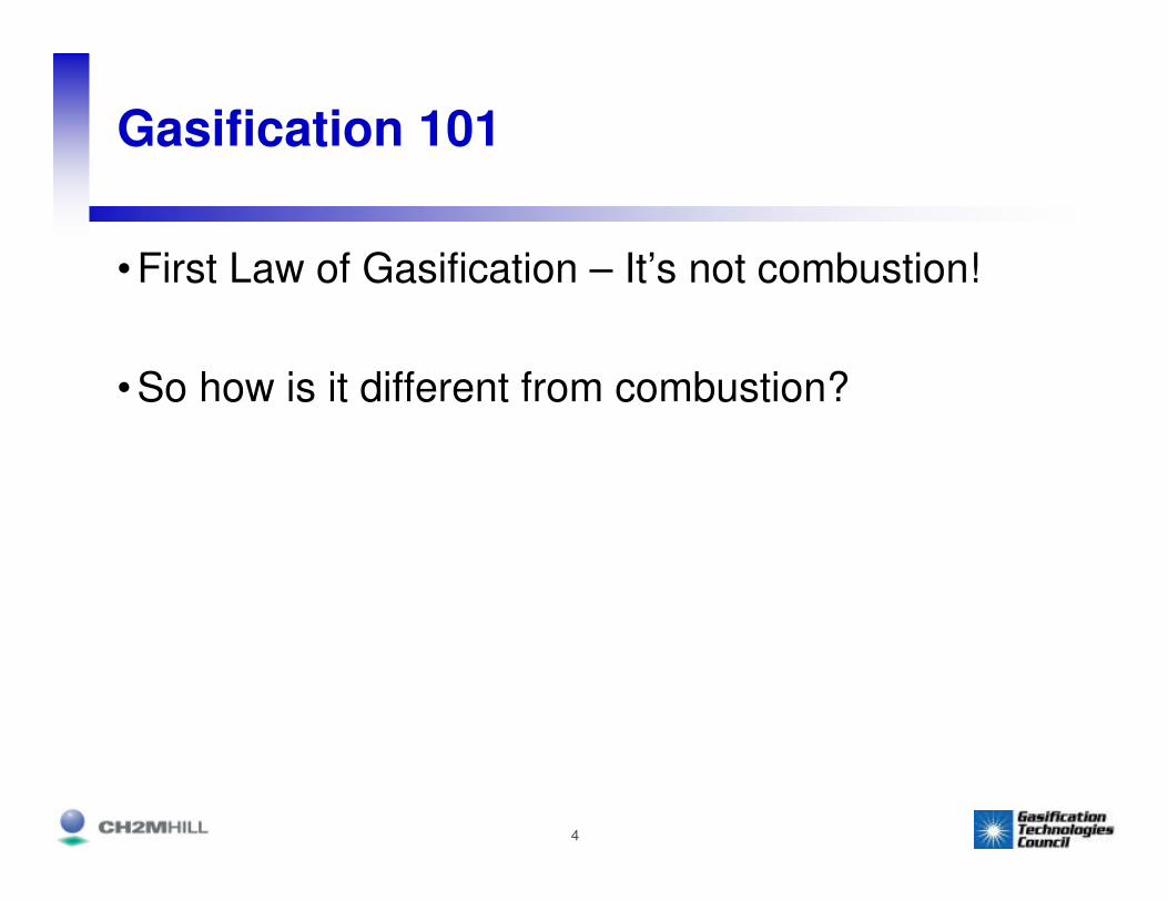
Gasification 101
• First Law of Gasification – It’s not combustion!
• So how is it different from combustion?

5
Combustion
C + O2 → CO2
Combustion of coal produces CO2 and
heat, which is used to produce steam for power generation
in a steam turbine generator

6
What is IGCC?
• Integrates two distinct technologies:
– Coal gasification from the chemical industry
– Combined cycle power generation from the power industry
• Advantages of IGCC
– Can use a wide range of feedstocks
– Takes advantage of high efficiency combined cycle power generation technology
– Has low emissions and saleable byproducts

7
Gasification
8
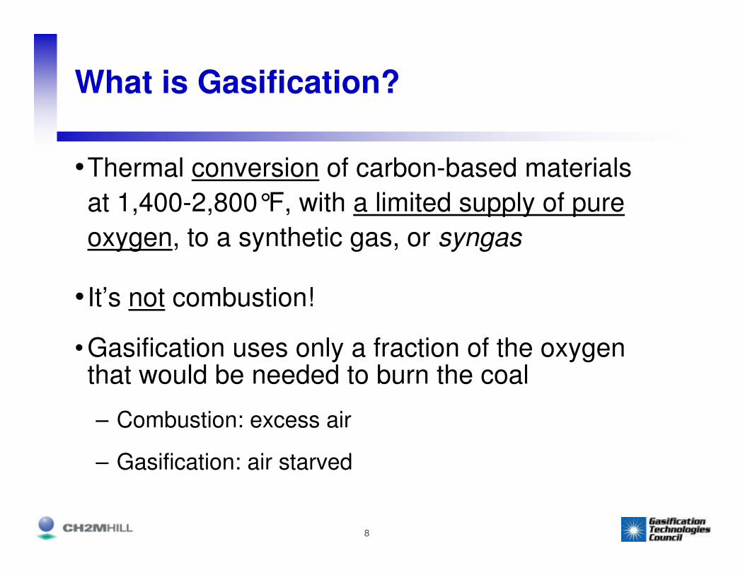
What is Gasification?
•Thermal conversion of carbon-based materials
at 1,400-2,800°F, with a limited supply of pure
oxygen, to a synthetic gas, or syngas
• It’s not combustion!
• Gasification uses only a fraction of the oxygen that would be needed to burn the coal
– Combustion: excess air
– Gasification: air starved

9
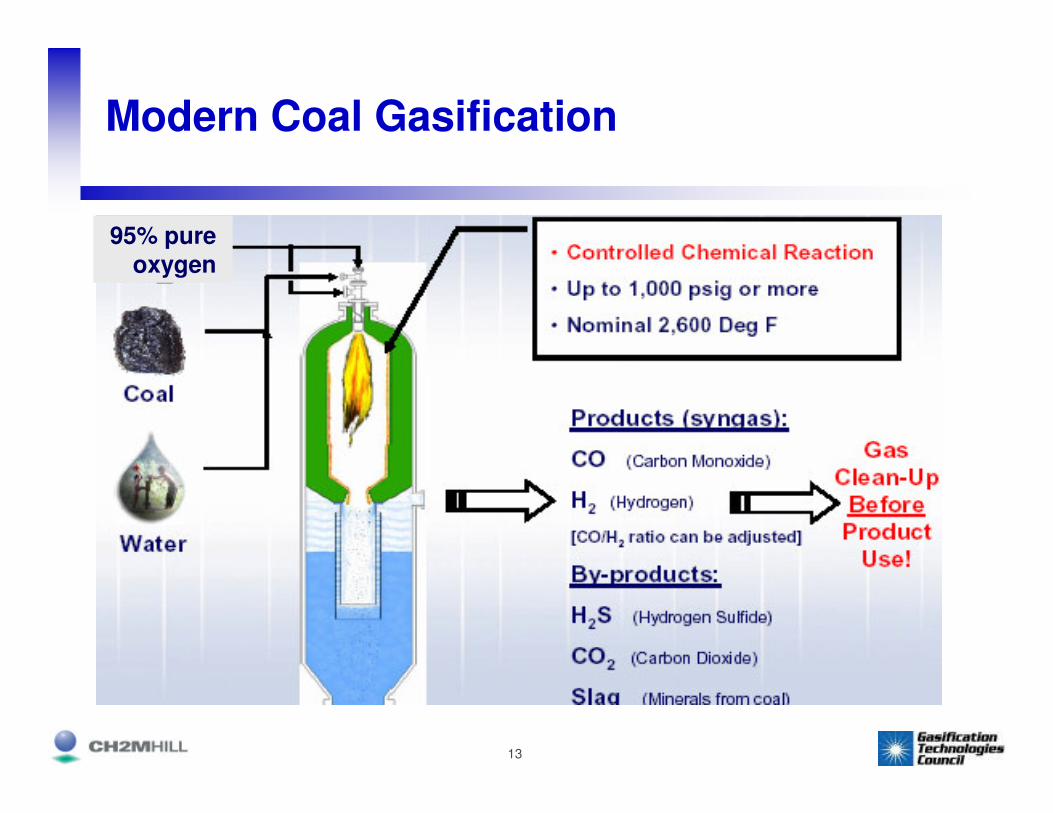
What’s in the Syngas?
• Syngas contains mostly hydrogen, carbon
monoxide, water vapor, carbon dioxide, and a
small amount of methane
• Syngas can be used as a fuel to generate power,
or to make chemicals & fuels
• Heating value is 250 Btu/scf (1/4 of natural gas)
10
How has Gasification been Used?
• Making “town gas” from coal (1792)
• Manufactured gas plants – prior to discovery and use of natural gas

11
How has Gasification been Used?
• Fuels
– WWII: Germany – no access to oil, but lots of coal
– Fischer-Tropsch process produced diesel and gasoline from syngas
– Cars and trucks used small wood gasifiers for fuel
wood gasifier

12
Modern Coal Gasification
13
Modern Coal Gasification
95% pure
oxygen

14
Commercial-scale Gasification

15
SASOL
• Located in South Africa
• Started up in 1955
• Lurgi gasifiers (97)
• Fischer-Tropsch process converts syngas to liquid fuels
• Now processes 90,000 tons coal/day into 160,000 barrels/day of transportation fuels
16
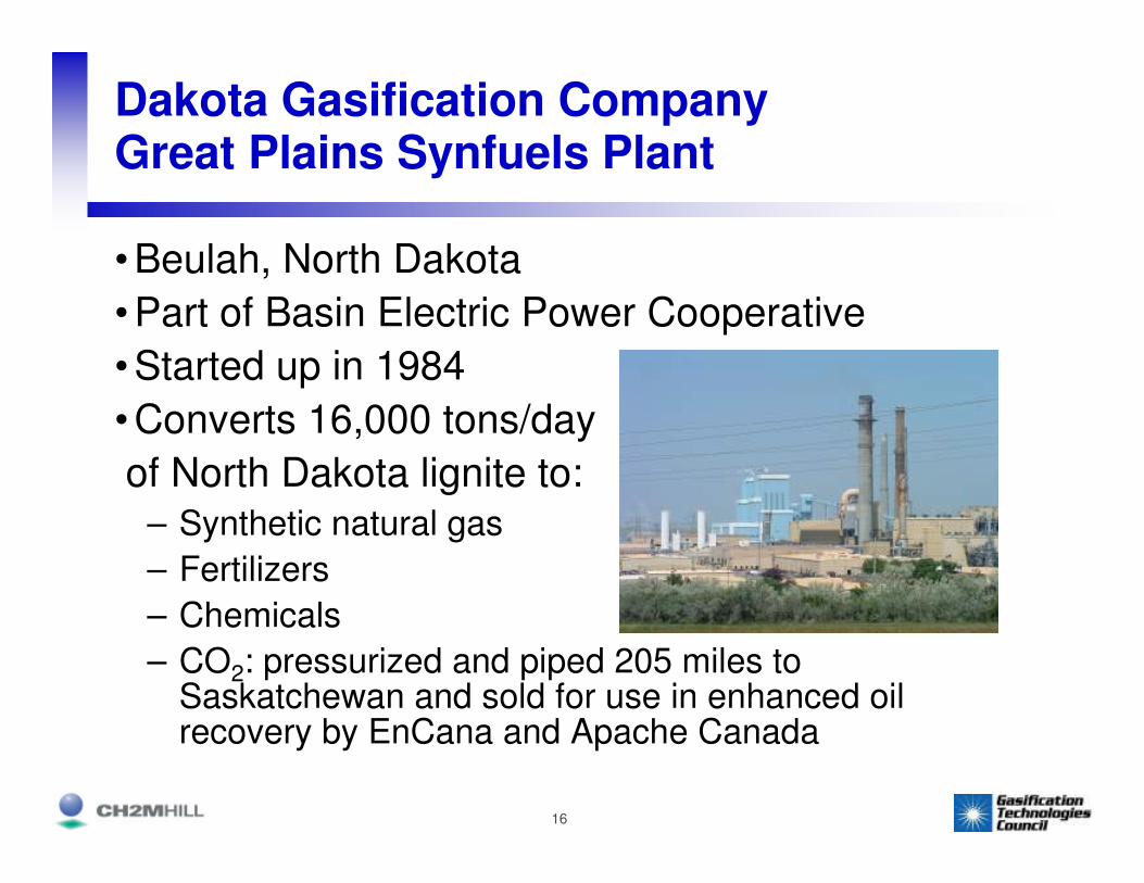
Dakota Gasification CompanyGreat Plains Synfuels Plant
• Beulah, North Dakota
• Part of Basin Electric Power Cooperative
• Started up in 1984
• Converts 16,000 tons/day
of North Dakota lignite to:– Synthetic natural gas
– Fertilizers
– Chemicals
– CO2: pressurized and piped 205 miles to Saskatchewan and sold for use in enhanced oil recovery by EnCana and Apache Canada

17
Eastman Chemical - Kingsport, Tennessee
• “Coal-to-Chemicals” Facility
• Started up in 1983
• Originally part of Eastman Kodak
• Texaco gasifiers
• Gasifies 1,200 TPD Central Appalachian medium sulfur coal
• Sulfur compounds and ash are removed from the syngas
• Syngas is used to make methanol, acetic acid, acetic anhydride, methyl acetate… and

18
Consumer Products

19
Coffeyville Resources
• Ammonia/fertilizer plant in Kansas
• Used high-cost natural gas to make ammonia
• Added pet coke gasification system
– GE Energy (Texaco) gasifier
– Produces syngas with CO and H2
– Syngas shifted to CO2 and H2
– CO2 removed, leaving concentrated H2
stream
– H2 used to make ammonia
– Significant production cost savings

20
Gasification Plants
• There are 117 operating gasification plants (not IGCC plants) with a total of 385 gasifiers in operation worldwide
• They are used primarily for gasifying coal, pet coke, natural gas, and refinery wastes
• They produce syngas for use in making chemicals, synthetic natural gas, hydrogen for ammonia, Fischer-Tropsch transportation fuels, and some power

21
Combined Cycle Power Generation
22
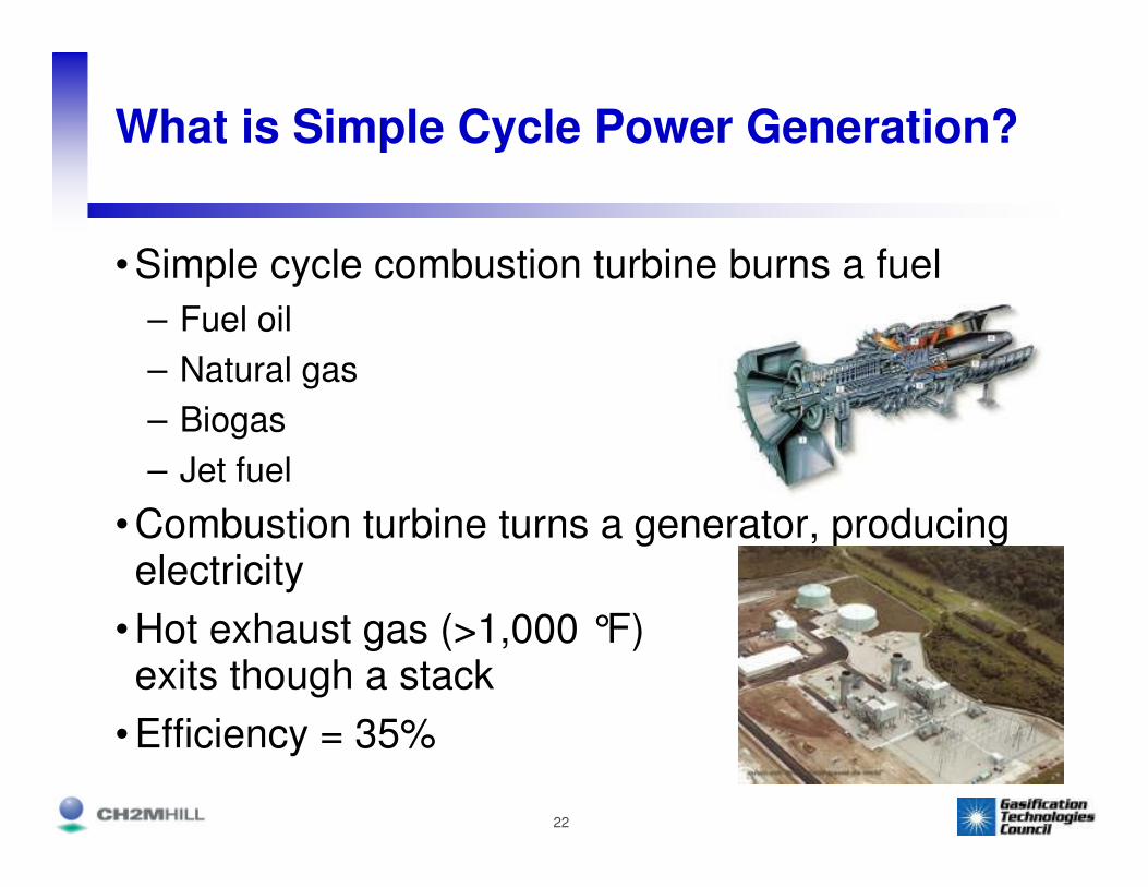
What is Simple Cycle Power Generation?
• Simple cycle combustion turbine burns a fuel
– Fuel oil
– Natural gas
– Biogas
– Jet fuel
• Combustion turbine turns a generator, producing electricity
• Hot exhaust gas (>1,000 °F) exits though a stack
• Efficiency = 35%

23
What is Combined Cycle Power Generation?
• Hot exhaust gas from combustion turbine is ducted through a Heat Recovery Steam Generator, or HRSG (boiler), where steam is produced
• Steam is piped to a conventional steam turbine-generator, producing more electricity

24
Combined Cycle
• Combination of simple cycle combustion turbine
generator + steam turbine generator =
combined cycle
• Combined cycle plant efficiency = 55+%

25
Combined Cycle – 2 Combustion Turbines and 1 Steam Turbine

26
How Does IGCC Work?
• Integrate the coal gasification process with a
combined cycle power plant
• Instead of using natural gas or fuel oil in the
combined cycle power plant, convert coal to a
clean-burning syngas and use it as a fuel

27
IGCC
Combined Cycle
Power Plant
Gasification Plant
28
Benefits of IGCC
• Take advantage of low-cost coal or pet coke
– Coal @$2.00/mmBtu, pet coke @$1/mmBtu
– Natural gas @ $7+/mmBtu
• Take advantage of high efficiency of combined
cycle power block
• Environmental profile: air emissions, liquid
discharges and solid byproducts
29
Where has IGCC Been Used?

30
Cool Water IGCC Demonstration ProjectDaggett, CA
31
Cool Water IGCC Demonstration Plant
• First demonstration of IGCC in the U.S.
• 1984-89
• 110 MW size
• Texaco gasifier and GE combined cycle
• 1,150 TPD Utah coal
• Co-funded by Southern California Edison, Texaco, GE &
EPRI
• Considerable information provided for development of
full-scale plant

32
Existing Coal-based IGCC Plants
Prenflocoal/cokePuertollano,
SpainPuertollanoELCOGAS
GE Energycoal/cokeMulberry, FLPolk Power
StationTampa Electric
ConocoPhillipscoal/cokeW. Terre Haute,
INWabash River
SG Solutions/ PSI Energy
Shellcoal/biomassBuggenum, Netherlands
Willem Alexander Centrale
Nuon
Gasifier Technology
FeedstockLocationFacilityCompany
33
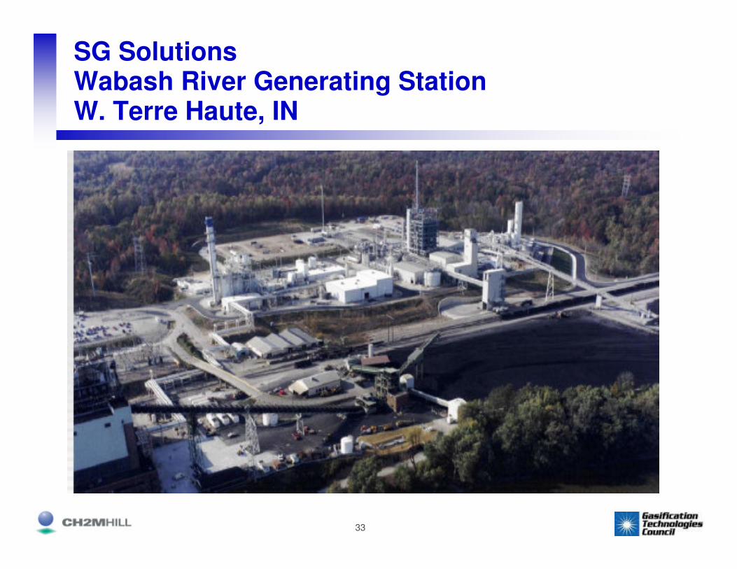
SG SolutionsWabash River Generating StationW. Terre Haute, IN
34
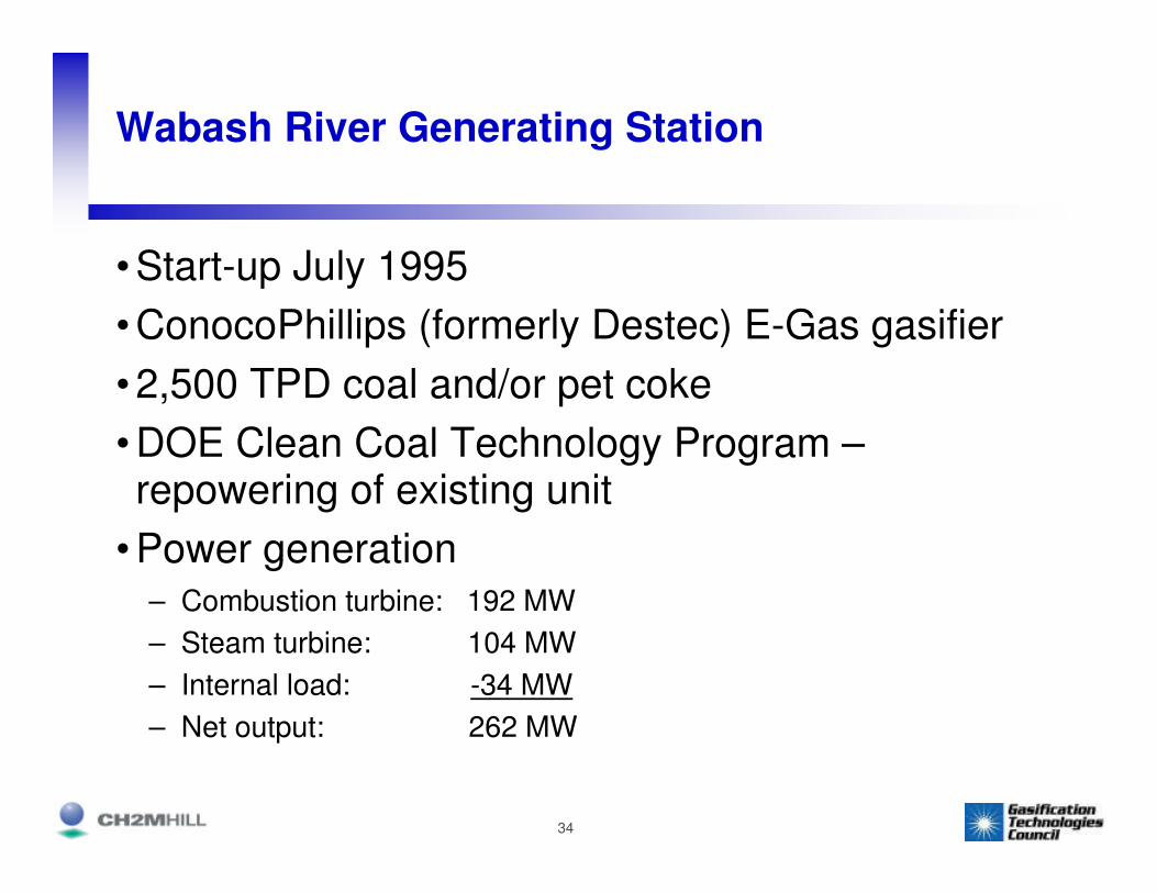
Wabash River Generating Station
• Start-up July 1995
• ConocoPhillips (formerly Destec) E-Gas gasifier
• 2,500 TPD coal and/or pet coke
• DOE Clean Coal Technology Program –repowering of existing unit
• Power generation– Combustion turbine: 192 MW
– Steam turbine: 104 MW
– Internal load: -34 MW
– Net output: 262 MW

35

36
Tampa Electric CompanyPolk Power StationMulberry, FL

37
Polk Power Station
• Start-up July 1996
• GE Energy (formerly Texaco) gasifier
• 2,500 TPD coal/pet coke blend
• DOE Clean Coal Technology Program – new plant
• Power generation– Combustion turbine: 192 MW
– Steam turbine: 120 MW
– Internal load: -60 MW
– Net output: 252 MW

38
Coal
2500 TPD
Rod M ill
W ater
Slurry
Tank
Slurry
Pump
Main Air
Compressor
32 MW
Product
Compressors
18 MW
Oxygen
2100 TPD
Coal/W ater
Slurry
Cold
Box
Dryers
Lockhopper
Slag &
W ater
Flyash
& W ater
Com pressor T urbine
Combustor
Generator
192 MW
Clean
Stack
GasAir
Condenser
Condensate
Pump
1600 psig
Saturated
Steam
Clean Syngas
W ater Scrubber
Diluent Nitrogen
5800 TPD
Radiant
Syngas
Cooler
Gasifier
Convective
Syngas
Cooler
F ina l Filte r
Cooling
W ater
MDEA Acid Gas Removal
Acid Gas
H2S + CO 2
To Su lfu ric
Acid Plant
Cooling
W ater
55 psig
Steam
Economized
Boiler
Feedwater
BFW Pump
Heat Recovery
Steam Generator
(HRSG)
Generator
125 MW
Steam Turbine
Raw
Syngas
COS
Hydrolysis(COS H2S)
Flyash &
Chloride
Remova l

39
AERIAL PHOTO
,
Gasifier Structure
ASU
Coal Silos
Combustion
Turbine
Steam Turbine
Sulfuric Acid Plant
Admin Bldg &
Control Room
Slurry Preparation

40
IGCC Technologies

41
GE Energy (formerly Texaco process)
• Coal-water slurry feed
• Oxygen-blown
• Refractory-lined gasifier
• Good for bituminous coal, pet coke, or blends of pet coke with low-rank coals
• GE Energy provides gasification technology
• GE Power provides combined cycle plant
• EPC alliance with Bechtel for guarantees on total IGCC plant
42
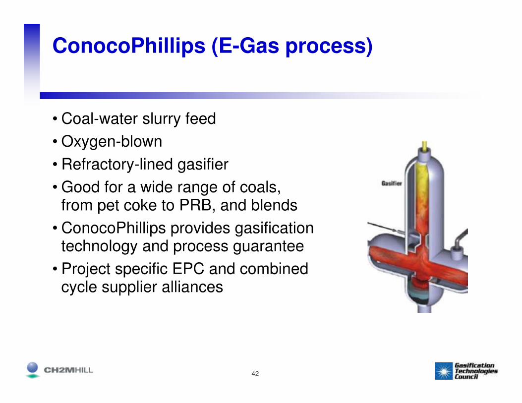
ConocoPhillips (E-Gas process)
• Coal-water slurry feed
• Oxygen-blown
• Refractory-lined gasifier
• Good for a wide range of coals, from pet coke to PRB, and blends
• ConocoPhillips provides gasification technology and process guarantee
• Project specific EPC and combined cycle supplier alliances

43
Shell
• Dry feed (coal is crushed and dried and then fed into gasifier)
• Oxygen-blown
• Waterwall in gasifier
• Good for wide variety of feedstocks, from pet coke to PRB
• Shell provides gasification technology
• Alliance with Black & Veatch and Uhde for engineering

44
Siemens (formerly FutureEnergy)
• Dry feed
• Oxygen-blown
• Waterwall screen in gasifier
• Good for a wide variety of feedstocks, from bituminous to low-rank coals
• Siemens provides gasification island and power block

45
Kellogg Brown & Root (KBR)
• Transport Gasifier
• Air-blown
• Based on catalytic cracker technology from refinery industry
• Pilot tested on wide range of coals at Power Systems Development Facility in Alabama
• Best on low-rank coals, i.e. PRB and lignite
• To be demonstrated by Orlando Utilities and Southern Power

46
Status of Commercial IGCC
• New fleet taking advantage of 10+ years of
operation in the U.S. and Europe
• Range of suppliers to choose from, for a wide
variety of coals and other feedstocks
• EPC alliances can provide important guarantees

47
Proposed IGCC Projects (in permitting)
ShellPet cokeCorpus Christi, TX
Nueces IGCCTondu
KBRPRBOrlando, FLOrlando Gasification Project
Southern Company and
Orlando Utilities
ConocoPhillipsPRB/Illinois #6/pet coke
Taconite, MNMesabaExcelsior Energy
GECoalTaylorville, ILTaylorville Energy Center
ERORA
GECoalOwensboro, KYCash Creek Generation
ERORA
ConocoPhillipsPRB/pet cokePort of Kalama, WA
Pacific Mountain Energy Center
EnergyNorthwest
GECoalEdwardsport, INEdwardsportDuke (Cinergy)
GECoalOH or WV Great Bend/Mountaineer
AEP
Gasification Technology
FeedstockLocationFacilityCompany

48
Proposed IGCC Projects w/CO2 Capture
TBDCoalIllinois or TexasFutureGenFutureGen
GE or CoPPet cokeSugar Land, TXLockwood RoadHunton Energy
GEPet cokeLos Angeles, CACarson Hydrogen Power Project
BP/Edison Mission Energy
Gasification Technology
FeedstockLocationFacilityCompany

49
Capacity of Proposed IGCC Facilities
• 600 MW (net) “reference plant” based on sufficient syngas to fully load two “F class” gas turbines
• Gross output: 780 MW
• Net output: ~630 MW
• Internal load: 150 MW (19% of gross output)
• Feedstock requirements
– Pet coke: 4,000 tons/day
– Bituminous coal: 6,000 tons/day
– PRB:7,800+ tons/day

50
Impacts of High Altitude
9,1009,000Net H.R., Btu/kWh (HHV)
560640Net Power, MW
120130Aux. Power, MW
670780Gross Power, MW
4,1004,700Oxygen, TPD
7,3008,300Feed Rate, TPD (PRB)
Air-cooled condenserCooling TowerCondenser Cooling System
1800 psig/1050 °F/1050 °FSteam Conditions
5,000 ft, 45 °F avg. amb.500 ft, 50 °F avg. amb.Site Conditions
Mine MouthMidwest
Source: ConocoPhillips

51Source: EPRI
IGCC design goal

52
IGCC Availability Improvements
• Lessons learned from 10+ years of experience n
– Materials of construction
– Spare equipment
– Gasifier refractory
– Burner design
• Next generation of IGCC should achieve 85+% availability
– Spare gasifier train may achieve 90% availability
– Back-up fuel can also improve unit’s availability
– Options must be balanced against cost of capital vs. fuel

53
Environmental Issues

54
Air Emissions

55
Technology Comparison
Pre-combustion clean-up of
small volume of syngas
Clean fuel and SCR
Post-combustion clean-up of
large volume of exhaust gas
Emission Emission ControlControl
Syngas in gas turbine
Natural gas in gas turbine
Coal in boilerCombustion Combustion
SyngasNatural gasCoalFuelFuel
Coal--FeedstockFeedstock
IGCCIGCCNGCCNGCCPCPC

56
IGCC - a Different Environment Than PC and NGCC
• Gasification occurs in a reducing atmosphere
– sulfur compounds are liberated as H2S
– removed by refinery industry technologies to levels ≥98%
• NOx is controlled by injecting N2 at 1:1 ratio with syngas, as well as saturating the syngas stream with water or steam (cools the flame)

57
Comparison of Air Emission Controls: PC vs. IGCC
Pre-sulfided activated
carbon bed
Wet scrubber, high
temperature cyclone,
ceramic filter
Syngas saturation and
N2 diluent
Amine system
removes H2S from syngas
IGCCIGCC
Inject activated carbon
ESP or baghouse
Low-NOx burners and SCR
FGD system
PCPC
MercuryMercuryPMPMNOxNOxSOSO22

58
Regulatory Requirements:What Air Regulations Apply to IGCC?
59
Applicable Air Regulations
• National Ambient Air Quality Standards (NAAQS)
• New Source Review (NSR) requirements, including Prevention of Significant Deterioration (PSD) and Non-Attainment NSR
• New Source Performance Standards (NSPS)
• National Emission Standards for Hazardous Air Pollutants (NESHAPs) including proposed Utility MACT and Combustion Turbine MACT rules
• Federal Acid Rain Program (Title IV)
• Operating permit (Title V)
• Clean Air Interstate Rule (CAIR)
• Clean Air Mercury Rule (CAMR)

60
• NSPS for Electric Utility Steam Generating Units (Subpart Da), from February 2006:
– Applies to IGCC combustion turbines that burn ≥ 75% “synthetic coal gas”
– When burning <75% syngas (12-month rolling average), Subpart KKKK applies
• This could be a problem during initial start-up
• Meeting the NSPS for NOx (15 ppm) may be difficult when burning natural gas in diffusion burners designed for syngas
New Source Performance Standards

61
Air Emissions
• EPA proposed changes to Subpart Da in
February 2007
• IGCC is covered by Subpart Da, if:
– “The combined cycle gas turbine is designed
and intended to burn fuels containing 50 percent
(by heat input) or more solid-derived fuel not
meeting the definition of natural gas on a 12-
month rolling average basis; and

62
New Source Performance Standards
• Integrated gasification combined cycle electric
utility steam generating unit or IGCC means a
coal-fired electric utility steam generating unit
that burns a synthetic gas derived from coal in a
combined-cycle gas turbine. No coal is directly
burned in the unit during operation.

63
New Source Performance Standards for IGCC
*output-based standards are on a gross generation basis,
so gross heat rate is used to calculate estimated input-based limit
2.6 lb/TBtu20 x 10-6 lb/MWh*Mercury
(bituminous coal)
0.015 lb/MMBtuLesser of 0.14 lb/MWh* or 0.015
lb/MMBtu
PMPM
0.185 lb/MMBtu1.4 lb/MWh* and minimum 95%
removal
SOSO22
0.132 lb/MMBtu 1.0 lb/MWh*NOxNOx
NSPS on Input NSPS on Input Basis (estimated)Basis (estimated)
NSPSNSPSEmissionEmission

64
Air Permitting
• Same coal delivery and handling emission points as PC units
• Same HRSG stack emission points as NGCC
• Air permitting requirements similar to NGCC and PC– Air dispersion modeling
– BACT analysis
– Emission controls
– Fugitive dust controls• Coal delivery, unloading and handling
– Cooling towers

65
Air Permitting
• Unique emission points depend on technology provider
– Flare
– Sulfur Recovery Unit tail gas incinerator
– Sulfuric Acid Plant stack
– Tank vents
– ASU cooling tower

66
What About SCR for IGCC?
• Technical issues
– The fuel is syngas, not natural gas as in NGCC
– Ammonium sulfate/bisulfate deposit in the HRSG, causing corrosion and plugging, requiring numerous washdowns
– No coal-based IGCC system in the world uses SCR
• Economic Issues
– No commercial guarantees yet with syngas
– Deep sulfur removal, i.e. Selexol, is required, with higher capital cost

67
Why SCR?
• SCR has been proposed for a wide variety of reasons by applicants:
– As BACT
– As Innovative Control Technology to reduce emissions beyond diluent injection
– As a trial/experiment, with emission limits only for natural gas use
– To evaluate SCR as part of DOE demonstration program with a syngas-fired combined cycle unit
– To minimize NOx emissions in order to reduce NOx emission allowance costs

68
NOx BACT
• EPA has addressed this in recent report
• Study notes technical problems with using SCR w/IGCC
• Looked at SCR, w/Selexol for deep sulfur removal
• EPA concluded that:
– even w/Selexol, problems are not solved
– additional cost and reduced output are negative impacts to IGCC
– BACT will continue to be a case-by-case issue
69
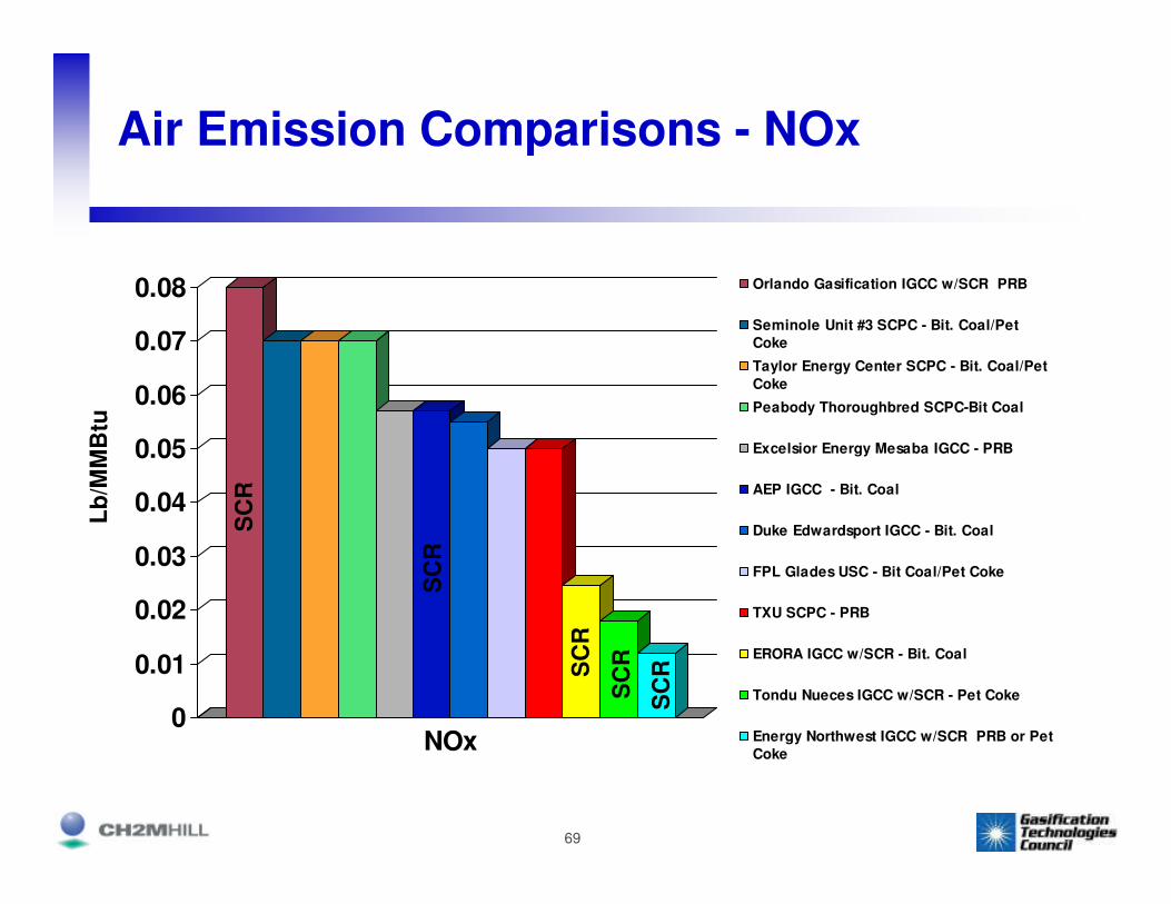
Air Emission Comparisons - NOx
0
0.01
0.02
0.03
0.04
0.05
0.06
0.07
0.08
NOx
Orlando Gasification IGCC w/SCR PRB
Seminole Unit #3 SCPC - Bit. Coal/Pet
Coke
Taylor Energy Center SCPC - Bit. Coal/Pet
Coke
Peabody Thoroughbred SCPC-Bit Coal
Excelsior Energy Mesaba IGCC - PRB
AEP IGCC - Bit. Coal
Duke Edwardsport IGCC - Bit. Coal
FPL Glades USC - Bit Coal/Pet Coke
TXU SCPC - PRB
ERORA IGCC w/SCR - Bit. Coal
Tondu Nueces IGCC w/SCR - Pet Coke
Energy Northwest IGCC w/SCR PRB or Pet
Coke
Lb
/MM
Btu
SC
RSC
R
SC
R
SC
R
SC
R

70
Air Emission Comparisons – SO2
0
0.02
0.04
0.06
0.08
0.1
0.12
0.14
0.16
0.18
SO2
Orlando Gasification IGCC PRB
Seminole Unit #3 SCPC - Bit. Coal/Pet Coke
Taylor Energy Center SCPC- Bit Coal/Pet
Coke
Peabody Thoroughbred SCPC Bit Coal
Excelsior Energy Mesaba IGCC - PRB
AEP IGCC - Bit. Coal
Duke Edwardsport IGCC - Bit. Coal
FPL Glades USC - Bit. Coal/Pet Coke
TXU SCPC - PRB
ERORA IGCC w/SCR - Bit. Coal
Tondu Nueces IGCC - Pet Coke
Energy Northwest IGCC- PRB or Pet Coke
Lb
/MM
Btu

71
Mercury Removal
• Pre-sulfided carbon beds
• >94% removal of vapor-phase mercury at Eastman Chemical
• Forms a mercury-sulfur complex
• Spent carbon disposed of in drums
once/year
• Most IGCC plants plan to use this technology
Source: Eastman Chemical

72
Water Issues

73
Water Consumption and Liquid Discharge Permits
• Water permits
– Consumptive use permits
• raw water treatment
• reverse osmosis and demineralizer
– State and local permits for potable water treatment and supply systems
– CWA Section 316(b) cooling water intakes
– NPDES permit for stormwater and wastewater discharges
• Zero liquid discharge system can eliminate need for discharge
– Local permits for sanitary sewer discharges or package treatment plants

74
• IGCC has no FGD system, so there are no large requirements for water to produce limestone slurry
• Cooling Water
– Example: for 780 MW (gross) IGCC unit, 460 MW is from CTs and 320 MW is from the ST
– So only ~40% of output is from ST
– Cooling water make-up needs are decreased
• Process water
– IGCC might include coal slurry preparation and syngas scrubbing
Water Consumption
75
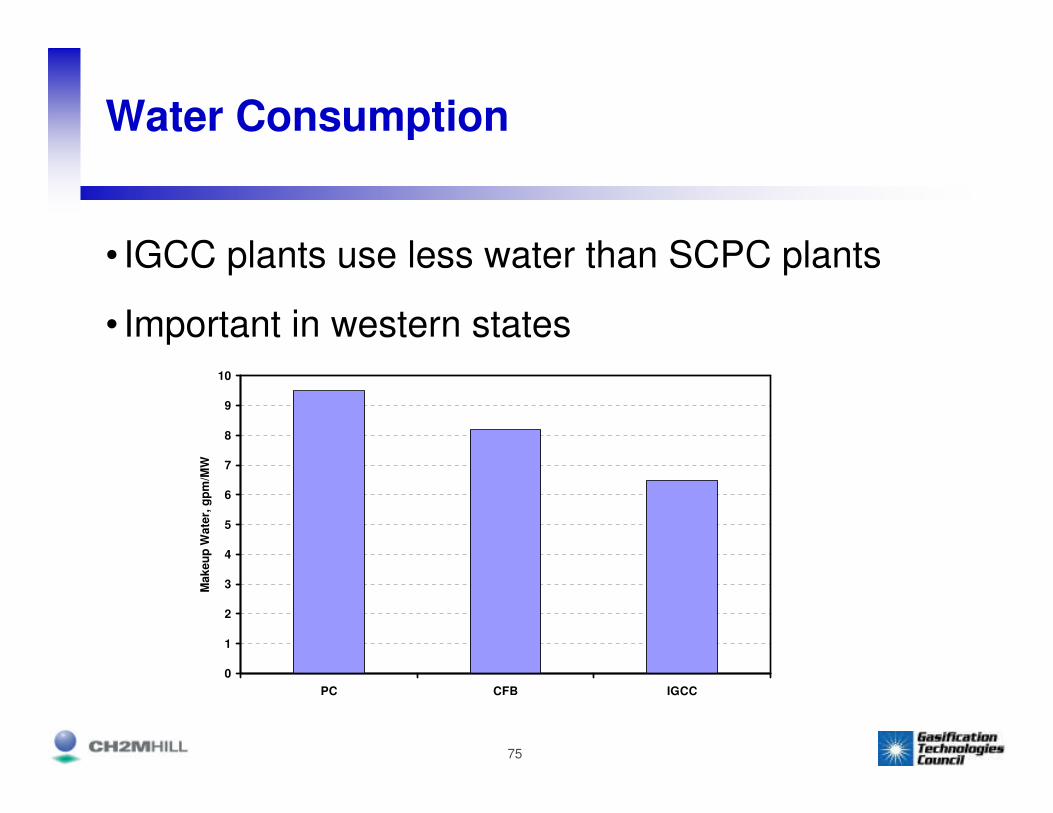
Water Consumption
• IGCC plants use less water than SCPC plants
• Important in western states
0
1
2
3
4
5
6
7
8
9
10
PC CFB IGCC
Makeu
p W
ate
r, g
pm
/MW
76
Solid Byproducts Issues

77
Comparison of Solid Byproducts –IGCC vs SCPC
SCPC
IGCC
Hundreds of acres if CCPs not marketable
Markets may or may not exist
Large volumes of fly ash, bottom ash,
FGD byproduct
Temporary storage for slag and molten sulfur
Excellent markets for sulfur
and slag
Small volumes of sulfur and slag
Land Requirements
Market UseSolid Wastes

78
• Ash is removed in molten form, then quench-cooled to form glassy, inert, saleable slag
Slag
79
Slag
• Very similar to slag from coal-fired boilers, but….
• It is not regulated as a coal combustion byproduct under RCRA, and does not have the same Bevill exclusion from Subtitle C (hazardous wastes)
• However, gasification slag does have a Bevill exclusion as a mineral processing waste
• Mineral processing wastes, as listed in 40 CFR 261.4(b)(7) include:
– “Gasifier ash from coal gasification”
80
Slag Use and Storage
• Used for making cement, asphalt filler, roofing shingles
• Need lined storage area with leachate collection system
• How much storage is needed?
– Temporary loadout area when slag is sold
– Temporary for facility start-up (unconverted carbon in slag)
– Permanent (on- or off-site) if no local market exists

81
Sulfur
• Recovered in molten form
• Transported by rail or truck
• Mass of sulfur produced from gasification is ~1/5 that of gypsum produced from FGD system on a PC unit

82
Solid Byproducts Comparison(Based on nominal 500 MW plant sizes)
0
50
100
150
200
250
300
350
400
450
PC-
Sub
PC-
USC
CFB IGCC PC-
Sub
PC-
USC
CFB IGCC PC-
Sub
PC-
USC
CFB IGCC PC-
Sub
PC-
USC
CFB IGCC
So
lid
Wa
ste
, lb
/MW
h
Sulfur
Spent Sorbent
Ash/Slag
Pittsburgh #8 Illinois #6 TX LigniteWyoming PRB
Sulfur
FGD Byproduct
Ash/Slag
Source: EPRI

83
Other Solid Byproducts
• Catalysts – occasional replacement
– COS hydrolysis
– Claus plant
– Sulfuric acid plant
– SCOT plant
– SCR
• Gasifier refractory – high chromium content
• Sand filters
• Carbon beds – hazardous waste disposal

84
Questions?