Embed Size (px)
Citation preview

Lentech Product Manual Lentech Product Manual
Lentech Automatics PO Box 1207, 3835 McBean St.
Richmond, ON, Canada, K0A 2Z0 (613)838-5390 tech (closed 12:00-1:00 pm EST)
(613)838-9996 orders (613)838-3265 fax www.lentechautomatics.com
Hours of Operation 9:00-5:00 EST
Jeff Thompson 1990 Ford Mustang LX
OSCA True Street @ 3220 lbs [email protected] Strip Terminator
8.8 rear with 3.55gears Cobra jet aluminum heads
Victor intake w/950hp Holley Single stage NOS (1000+ whp)
Len Bertrand 1971 Ford Maverick
OSCA Pro Stock 9.33@147mph
Strip Terminator Lockup 358CI NA
Blue Thunder 430 heads Single 4BBL Carb
9” rear with 5.67 gears
Dave King 2004 Ford Mustang Cobra
[email protected] 4R70W Street Terminator Plus
Whipple Charger @24psi 60lb injectors w/ MD fuel line upg.
9.5” 4K rpm convertor Stainless Works Headers/exhaust
JLT cold air induction

Lentech Product Manual Lentech Product Manual
As a long time mechanic and drag racer, Len Bertrand recognized the need for a performance overdrive transmission. Being a transmission specialist, Len was familiar with the Automatic Overdrive which had been in production since 1980. In 1990, his personal project car (1979 Capri) was fitted with an AOD to replace the C4. Within weeks of the installation, the transmission had failed. After carefully examining oil circuit diagrams, it was determined the factory shift pattern had been a major factor in the transmissions early demise. Upon this discovery, Len constructed the first valve body with the 1,2,3/4 shift arrangement. It was soon after, (with these modifications) other local enthusiasts began requesting that these modifications be performed to their own project cars. As a result of growing interest and demand for the transmission, Lentech Automatics was founded in 1994. At Lentech Automatics, we take pride in providing you with the most innovative AOD technology available. Every product is fully tested and backed by an unprecedented warranty. We are also committed to continual development of new products and refinement of existing products. Our technical staff is trained to recommend only components appropriate to your combination. If you have any further questions relating to the installation or use of your Lentech product, feel free to call us on our technical hotline. Congratulations on your purchase of a Lentech Product!
1 38

Lentech Product Manual Lentech Product Manual
Page Item 3 Disclaimer 4 Transmission/Convertor Installation 8 Valve Body Installation 11 TV/Direct Clutch Test Port Locations 11 Trans Cooler In/Out Ports 12 Drilling Locations 13 AOD Wiring 13 Legend 14 Street Terminator/Strip Auto 15 Strip Terminator w/Brake 17 Strip Terminator w/Brake, 2-Step 19 Strip Terminator Lockup w/2-Step 21 AODE/4R70W Connector pin diagrams 24 Maintenance 25 Operation 27 Transmission Cooling Tips 29 Troubleshooting 32 Product Options 34 Order, Return and Cancellation Policies 35 Warranty
237

Lentech Product Manual Lentech Product Manual
Please read this disclaimer before installing this product. This is a racing product, and is not guaranteed to comply with all Federal or State Highway regulations. We are not responsible for the accidental selection of a gear ratio that may be inappropriate for road speed, or for any damages incurred by the misuse of this product however caused. By installing this product you are claiming: You have read and understand that Lentech Automatics is not responsible for the use or misuse of the product, or the vehicle in which it is being used. A professional technician should carry out installation. Any technical questions not addressed in these instructions may be directed to Lentech Automatics staff.
3 36

Lentech Product Manual Lentech Product Manual
When purchased with our torque convertor Lentech Automatics Transmissions are covered by a lifetime limited warranty from the date of invoice against defects in workmanship and materials *See below for details All Lentech Automatics custom built torque converters are guaranteed for a period of 2 years from the date of invoice against defects in workmanship and materials. **See below for details All Lentech Automatics custom built valve bodies are guaranteed for a period of 3 years from the date of invoice against defects in workmanship and materials. ***See below for details Lentech Automatics is a company with a strong commitment to customer satisfaction. As such, we reserve the right to extend warranties at our own discretion. *From the date of invoice, a $250 deductible applies within the first year. A $995 deductible applies thereafter. These figures do not include the torque converter or other upgrades not originally purchased. Lentech Automatics' transmissions warranties do not cover any shipping, duties or brokerage fees or any other charges incurred in the return of our products. We accept no responsibility for any expenses or damages resulting from the purchase, installation and use of our products. All prices are in U.S. dollars. "Warranty is transferable." **Lentech Automatics' torque converters warranty covers any defects in parts and workmanship for a period of 2 years. We accept no responsibility for any expenses or damages resulting from the purchase, installation and use of our products. Shipping, duties or brokerage fees or any other charges incurred in the return of our products are not included in the warranty. ***Lentech Automatics' valve bodies warranty covers any defects in parts and workmanship for a period of 3 years. A minimum $100 service fee applies after the first year (not including parts). We accept no responsibility for any expenses or damages resulting from the purchase, installation and use of our products. Shipping, duties or brokerage fees or any other charges incurred in the return of our products are not included in the warranty. 30-day satisfaction guarantee on all valve bodies: If within 30 days you are unsatisfied with our valve body, return for a full refund.
• The vehicle should be raised to a minimum height of 1.25 feet. This
will enable you to move around quite freely under the vehicle. CAUTION: jack stands or ramps should be used under the car. DO NOT attempt to remove the transmission when car is on jacks or ramps. It is recommended that you rent a transmission jack to lower, and raise the transmission, as this is the easiest method. You may also use a floor jack, as long as you use caution.
• Drain transmission. This can be done by removing the Oil Pan, or in some cases, you may have a drain plug on the pan. Replace pan or drain plug when drained.
• Remove front dust cover. This will enable you to remove the convertor bolts. There are (3) bolts on G.M. and (4) bolts on Ford. You will have to rotate the engine in order to remove all of the convertor bolts.
• Remove starter (on Ford). • Disconnect all linkages, electrical connectors, vacuum lines,
speedometer cables, etc. (NOTE: on some vehicles, transmission shift is controlled by a “throttle valve cable” which should be disconnected at the carburetor or throttle body.)
• Unbolt drive shaft and remove. Take care that the U-Joint cups do not fall off as you will lose the needle bearings inside the cups.
• Place transmission jack under the oil pan and remove the cross member.
• Disconnect cooler lines. It is best to use a flare nut wrench so you will not damage the cooler line fittings. Disconnect filler tube and remove.
• Remove all (6) bell housing bolts. Take a long, heavy screwdriver or pry bar and pry the transmission and torque convertor away from the engine as a complete unit. This should take very little pressure. If resistance is felt, check that all bolts are out. After doing this, lower the jack slowly, making sure all linkages, cooler lines, electrical connectors, vacuum lines, etc. are clear of the transmission. Place on a work bench if one is available.
• Remove torque convertor by pulling it straight out of the bell housing. • Remove the flex plate from the end of the crankshaft and check for ring gear
wear and any visible cracks as it is a must to replace if either one of these conditions exist. In some cases it will be necessary to enlarge the flex plate holes to accommodate the larger size bolts used in our convertors. It is advised that you do not drill them any larger then 1/32 over the bolt
435

Lentech Product Manual Lentech Product Manual
size. NOTE: on 5.4L/4.6L applications with small diameter, high stall convertors it is necessary to enlarge an existing set of small pilot holes to accommodate the larger bolt circle on the supplied torque convertor. Replace the flex plate on the end of the crankshaft.
• Install at least 1 litre / US quart of ATF (transmission fluid) into the hub of the convertor. Pour slowly as this will prelube the inside at startup. Using some type of lubricant such as Vaseline or transmission oil, lube the hub of the convertor. Install carefully into the front of the transmission using a rotating motion and being careful not to damage the front seal on the pump. The convertor must go all the way in so as the hub will engage the pump gears. There should be approximately 1 inch from the face of the bell housing to the mounting pad face on the convertor. Replace the transmission in the vehicle by reversing the removal procedure. CAUTION: DO NOT, under any circumstances, try to install the convertor on the motor and then try to install the transmission. CAUTION: DO NOT use the bell housing bolts to draw the transmission onto the engine block. The transmission must slide onto the dowel pins freely and fit flush against the engine block by hand. If this cannot be done, then the convertor is not engaged all the way into the pump. Once the transmission fits flush to the engine, install (2) bell housing bolts. After doing so, check and make sure the convertor rotates freely inside the bell housing. On Ford products it will be necessary to align the convertor drain plug and bolt studs with the holes in the flex plate. You should be able to move the stud back and forth in the holes if installed properly.
•
• Pour in (4) liters/quarts of transmission fluid, and have up to (4) more liters/quarts ready to go. Set hand brake, start engine, and pour 3 more liters of fluid into the transmission. Run the vehicle through the gears, check oil level and add until full. NEVER STAND IN FRONT OF VEHICLE!.
At Lentech Automatics we provide a service of "custom" built automatic transmissions to enthusiasts around the world. The requirements for ordering a Lentech custom built transmission and components are as follows:
• Orders taken by phone require VISA or MasterCard only • Orders accepted by mail are by cheque or money order only (no cash) • Orders on complete "custom" built transmissions require a minimum
50% deposit. Balance due 48 hours before ship date. • Orders on complete "custom" built transmissions are subject to a
minimum $100 cancellation fee within 24 hours of order received. • Orders on complete "custom" built transmissions cancelled after 24
hours are subject to a 50% cancellation fee • No refunds or credits for custom built transmissions and torque
converters. • No refunds of shipping costs for returned items • Damaged or missing components must be reported to Lentech
Automatics within 24 hours of receiving shipment To return merchandise, you need prior authorization from Lentech and to complete a Return Merchandise Authorization (RMA) form. The form can be found at www.lentechautomatics.com or a copy can be faxed to you. All returns from within the US must be sent (freight prepaid) to:
Lentech Automatics, 800 Proctor Ave,
Ogdensburg, NY, 13669,
U.S.A. All returns from within Canada or other countries must be sent (freight prepaid) to:
Lentech Automatics, 3835 McBean St, Richmond, ONT,
K0A 2Z0 CANADA
5 34
It is recommended that a minimum 0.062", to a maximum 0.125" clearance exist between the converter mounting pads and flywheel/converter mating surface. (Measured with convertor fully installed into transmission) FAILURES RESULTING FROM INSUFFICIENT RUNNING CLEARANCE WILL VOID WARRANTY!

Lentech Product Manual Lentech Product Manual
Planetary Gear Sets 2.84 OEM Cast Aluminum 2.84 Billet Aluminum 2.66 Billet Aluminum 2.40 Billet Aluminum 2.18 Billet Aluminum Bellhousing Options 429/460 GM->AOD FE (Ford Family) Mopar Small Block 4.6L->AOD Mopar Big Block SBF157 SBF164 Adapter Plates 429/460 to AOD GM->AOD Miscellaneous Lentech Cast Aluminum oil pan Lentech Fabricated Oil Pan Oil Coolers Universal TV Cable Kit Flywheels Wiring Kits
Throttle Pressure Setup – VERY IMPORTANT (AOD Only) The throttle valve (TV) setup is a means to provide the AOD transmission with an input to correlate shift points with throttle position. It can be very sensitive, but once adjusted properly, provides consistent shift timing. It can also serve as a safeguard which prevents the transmission from shifting into OD under full power.
Baseline Adjustment Cable Type Adjust cable so it is pulled out all the way when the accelerator is placed at “Wide Open Throttle” Linkage Type • Adjust linkage so rod is pushed a far as it will travel with
accelerator at “Wide Open Throttle” • Test drive vehicle and if it shifts too late (delayed), back it
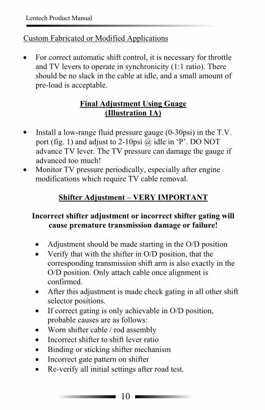
down 1/8th of an inch and try again. • After test drive, recheck fluid level Custom Fabricated or Modified Applications • For correct automatic shift control, it is necessary for throttle
and TV levers to operate in synchronicity (1:1 ratio) There should be no slack in the cable at idle, and a small amount of pre-load is acceptable.
633

Lentech Product Manual Lentech Product Manual
Final Adjustment Using Guage Illustration 1A
•
• Monitor TV pressure periodically, especially after engine modifications which require TV cable removal.
Shifter Adjustment – VERY IMPORTANT
Incorrect shifter adjustment or incorrect shifter gating will
cause premature transmission damage or failure! • Adjustment should be made starting in the O/D position
• Verify that with the shifter in O/D position, that the corresponding transmission shift arm is also exactly in the O/D position. Only attach cable once alignment is confirmed.
• After this adjustment is made check gating in all other shift selector positions.
• If correct gating is only achievable in O/D position, probable causes are as follows: • Worn shifter cable / rod assembly • Incorrect shifter to shift lever ratio • Binding or sticking shifter mechanism • Incorrect gate pattern on shifter
• Re-verify all settings after road test.
Valve Bodies Street Cruiser AOD Street Terminator AOD (calibration #1,2,3) Street Terminator AODE/4R70W (calibration #1,2,3) Strip Terminator AOD (F/M or auto shift) Strip Terminator AOD with Trans Brake (Full Manual only) Strip Terminator AODE/4R70W (F/M or auto shift) Strip Terminator AODE/4R70W with Trans Brake (F/M or auto shift)
Transmissions Street Cruiser AOD/AODE/4R70W Street Bruiser AOD Street Terminator AOD/AODE/4R70W Strip Terminator AOD/AODE/4R70W Street Terminator Plus AOD / AODE / 4R70W Strip Terminator AOD/AODE/4R70W Strip Terminator Lockup AOD RV2000 AOD Convertors Street Cruiser (12” Non-Lockup) 12” SS (Lockup or Non-Lockup) Street Bruiser 9” (Non-Lockup) 10” or 9.5” Bracket Master (Lockup or Non-Lockup) 9”, 8” or 7” Racemaster (Lockup or Non-Lockup) Shafts Solid 1-piece (Stage I or II) Hardened Hollow (Lockup only Stage I or II) Hardened Direct (3/4 Stage I or II requires stage II direct drum) Stage II A.O.D.E./4R70W midshaft (requires stage II direct drum)
7 32
Install a low-range fluid pressure gauge (0-30psi) in the T.V. port (fig. 1) and adjust to 2-10psi @ idle in ‘P’. DO NOT advance TV lever. The TV pressure can damage the gauge if advanced too much!

Lentech Product Manual Lentech Product Manual
Late Upshifts • T.V. cable stuck or incorrectly adjusted • T.V. plunger jammed • Jammed governor assembly
Harsh 4-3 Downshifts on Deceleration • T.V. cable incorrectly adjusted or jammed Trans Slips or Engine Cuts Loose Under Hard Accel in 2nd Gear • No O/D delete function • No T.V. cable linkage No 3-4 Delete Operation • Wiring incorrect or Low voltage to 3-4 delete solenoid • Plugged solenoid or valve body • Defective solenoid • Valve body gasket incorrectly aligned • Loose valve body bolts No Trans Brake Operation • Wiring incorrect or low voltage to trans brake solenoid • Missing bracket on trans brake solenoid • Loose valve body bolts • Gear selector not in manual 1st position • Stuck governor • Stuck 1-2 shift valve • Missing or damaged reverse clutch sealing rings Trans Brake Always on in Manual 1st • Stuck trans brake valve • Plugged trans brake solenoid • Shorted 3-4 pressure switch • Incorrect wiring of trans brake circuit • Shorted trans brake button
Caution: Allow vehicle to cool 2 hours from operating temperature before disassembling. Remove: • Oil pan bolts • Oil pan • Gasket • Filter • 25 main control bolts (8mm hex head bolts) • Main control assembly • Main control gasket Install: • Main control gasket on main control (use transmission gel or
Vaseline) to secure gasket to separator plate of main control. • Carefully match/align holes as best as possible • Fit main control into position (be sure to engage manual lever
and T.V. linkage if applicable in the process). Install all main control bolts, by hand, all the way (do not use power tools).
• Torque centrally located bolts and then the perimeter bolts in 3 stages, 30-60-90 inch pounds.
• Finally torque the centrally located bolts to 100 inch pounds. • Double and triple check all bolt torques. One missed bolt can
cause erratic shifts and premature transmission failure. • Install filter, pan and pan gasket. • Torque pan bolts to 70 inch pounds. • Install 4 liters/quarts of fluid. (See page 21 for recommended
fluids) • With gear selector in neutral, the vehicle level, and the wheels
approximately 6” off the ground, start engine and allow to idle
831

Lentech Product Manual Lentech Product Manual
• Add fluid until full level is reached. Always check both sides of dipstick.
• When a steady full level is established, engage transmission in reverse and then drive.
• Recheck fluid level and, if necessary, add to achieve the full level mark.
• Operate vehicle through all ranges and recheck level again. • Re-torque pan bolts after 500 miles • See page 12 (figure 2) for drill locations if equipped with O/D
delete or transbrake.
Throttle Pressure Setup – VERY IMPORTANT (AOD Only) The throttle valve (TV) setup is a means to provide the AOD transmission with an input to correlate shift points with throttle position. It can be very sensitive, but once adjusted properly, provides consistent shift timing. It can also serve as a safeguard which prevents the transmission from shifting into OD under full power.
Baseline Adjustment Cable Type Adjust cable so it is pulled out all the way when the accelerator is placed at “Wide Open Throttle” Linkage Type • Adjust linkage so rod is pushed a far as it will travel with
accelerator at “Wide Open Throttle” • Test drive vehicle and if it shifts too late (delayed), back it
down 1/8th of an inch and try again. • After test drive, recheck fluid level
• Stuck valve body • Missing governor rings No Upshift When Cold • Stuck governors • Stuck valve body No 1-2 Upshift • Broken intermediate one way clutch • Jammed 1-2 shift valve • Damaged or missing intermediate clutch or seals No 2-3 Upshift • Burnt 3-4 clutch assembly • Damaged or missing 3-4 clutch seals • Stuck 2-3 shift valve • Loose valve body bolts • Incorrectly aligned valve body gasket • Broken 3-4 shaft No 3-4 Upshift • O/D servo in not engaged to O/D band strut • Burnt or Missing O/D band • Damaged or missing O/D servo seals • No 3-4 accumulator on pre-89 models (N/A on Lentech valve bodies) • Broken 3-4 shaft Soft Mushy Shifting • Incorrect shifter adjustment (shift lever not detenting positions correctly) • Low or inaccurate fluid reading
Shift Quality & Driveability Early Upshifts • T.V. cable disconnected or incorrectly adjusted • Loose valve body bolts • Incorrectly aligned valve body gaskets
9 30
Lentech Product Manual Lentech Product Manual
General No Movement Forward or Reverse • Manual valve not engaged to detent selector plate • Low fluid level • Pump damaged • Burnt clutches • Loose valve body bolts • Plugged filter • Loose pump bolts No Movement Forward • Disconnected manual valve • Burnt forward clutches • Improper shift linkage adjustment • Missing or damaged forward clutch seals • Stuck 3-4 shift valve • O/D delete system not connected or energized. No Movement Reverse • Burnt reverse clutches • Broken low/reverse band • Low & reverse servo piston damaged • Stuck transbrake solenoid or electrical malfunction • Missing or damaged reverse clutch seals Delayed Engagement • Low fluid level • Defective seals (forward or reverse) in clutch assembly • Plugged filter • Loose valve body bolts • Worn pump No Upshift • Stuck governor • Governor installed backwards • T.V. plunger jammed • T.V. cable jammed or incorrectly adjusted
Custom Fabricated or Modified Applications • For correct automatic shift control, it is necessary for throttle
and TV levers to operate in synchronicity (1:1 ratio). There should be no slack in the cable at idle, and a small amount of pre-load is acceptable.
Final Adjustment Using Guage
(Illustration 1A) •
• Monitor TV pressure periodically, especially after engine modifications which require TV cable removal.
Shifter Adjustment – VERY IMPORTANT
Incorrect shifter adjustment or incorrect shifter gating will
cause premature transmission damage or failure!
• Adjustment should be made starting in the O/D position • Verify that with the shifter in O/D position, that the
corresponding transmission shift arm is also exactly in the O/D position. Only attach cable once alignment is confirmed.
• After this adjustment is made check gating in all other shift selector positions.
• If correct gating is only achievable in O/D position, probable causes are as follows:
• Worn shifter cable / rod assembly • Incorrect shifter to shift lever ratio • Binding or sticking shifter mechanism • Incorrect gate pattern on shifter • Re-verify all initial settings after road test.
1029
Install a low-range fluid pressure gauge (0-30psi) in the T.V. port (fig. 1) and adjust to 2-10psi @ idle in ‘P’. DO NOT advance TV lever. The TV pressure can damage the gauge if advanced too much!
Lentech Product Manual Lentech Product Manual
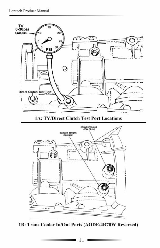
1A: TV/Direct Clutch Test Port Locations
1B: Trans Cooler In/Out Ports (AODE/4R70W Reversed)
Placement of Transmission Coolers Whenever possible transmission oil coolers should be placed in the front of the vehicle, in direct airflow. If mounting the transmission cooler to a condenser or radiator, use a suitable spacer between the components to allow an air gap. Where this is not feasible, a small electric fan can be used to generate the required airflow. Transmission Cooler Lines Factory transmission cooler lines are usually 5/16” steel, which is adequate for mild street machines. In more extreme conditions 3/8” steel or –6AN braided lines yield greater volume in conjunction with associated fittings. Do not run lines in close proximity to exhaust components and avoid tight radius bends.
11 28

Lentech Product Manual Lentech Product Manual
Strip Terminator AODE / 4R70W Through the use of fixed line pressure, 26 spline 3-4 clutch drum and shaft, and patented Lentech reverse/third technology, the Strip Terminator AODE / 4R70W dramatically increases torque capacity over ANY existing 4R70W designs. Available in manual or automatic shift models with / without transbrake. This model may be ordered with or without convertor clutch lockup operation. NOTE: If convertor lockup is requested, a multiple disc unit is recommended.
When choosing a transmission cooler, it is preferable to use one that is not “self regulating”. Lentech Automatics recommends the use of auxiliary transmission coolers with a rating of 20,000 GVWR for all of its products. The temperature of the fluid in an automatic transmission greatly affects its lifespan and operation. Excessive fluid temp will eventually harden seals and breakdown transmission fluid which can lead to premature transmission failure. Any automatic transmission equipped with a high stall torque convertor should have a transmission temperature gauge installed in the vehicle. Ideal fluid temperature is 200 degrees Farenheit or less, with the maximum allowable being 240 degrees Farenheit. This temperature should be measured in the sump pan for the most correct reading. If excessive transmission fluid temperature persists a simple cooler flow volume check may help to diagnose the condition of the transmission pump, oil cooler and lines. To perform the cooler flow check, complete the following steps:
• Disconnect transmission oil cooler output line (returning to transmission) (Refer to illustration 1B)
• Install small length (3-4 foot) of hose to oil cooler output fitting • Place hose into pail or basin with a capacity of 5 gallons. Secure to pail /
basin or have someone hold it in place. • With the vehicle in park, start the engine and run for 30 seconds and
shut down. Do not run engine for longer then 30 seconds or damage can result.
• Re-install cooler lines as per original installation. • Measure volume of transmission fluid collected. 2 quarts is average
cooler flow. • Re-install transmission fluid or same volume of new fluid.
2: Wiring/Drill locations
Important: Park rod is not to contact fittings! Location for hole to be tapped for case connector
NOTE: Drill bit should be 21/64”, tap hole to 1/8” NPT.
Pressure Switch: Delco Part # 08642473
3 1/2”from rear edge
of case
2.7” from edge of case
Front
1227

Lentech Product Manual Lentech Product Manual
Wiring - Legend
car without the losses associated with a high stall converter thanks to the controllable lock-up feature. The lock-up valve body operates at a fixed line pressure and does not use a throttle pressure linkage. It is available in full manual shift only. This transmission is designed for and best suited to serious high RPM competition vehicles that would rarely see any on-road duty. Overdrive Operation (All AOD Models) All fully automatic models of Lentech AODs (Street or Strip series) with electric O/D delete require +12V to keep overdrive disabled. Manual shift models by contrast require +12V to ENGAGE O/D. NOTE: On Manual shift models pre-dating Aug 1/05 an O/D delete system was used to inhibit O/D. These models will not engage any forward gears if this system is not energized. Street Terminator AODE / 4R70W Street Terminator AODE/4R70W transmissions maintain fully automatic shifting for streetability. Each unit receives several key internal modifications and upgrades for increased durability. Performance is aided by the high performance stall convertor with heavy-duty convertor clutch. It is highly recommended that higher than stock axle ratio be installed (3.55 or higher) in conjunction with this transmission model. Auxiliary transmission oil coolers are also highly recommended. Street Terminator Plus AODE / 4R70W By fixing line pressure, one liability of the electronic AODE/4R70W can be eliminated. Lockup can be eliminated to reduce rotating mass in the convertor and prevent contamination from convertor slippage. The Strip Terminator AODE/4R70W is available with or with out a transbrake. Both models are available in auto or manual shift. TRANSBRAKE MODELS: On models equipped with transbrake, it is possible to engage the transbrake in any forward gear (except overdrive), DO NOT use the transbrake unless the vehicle is at a COMPLETE stop. In order to prevent severe driveline damage, a dual in-series switch setup is preferred. (Main trigger and separate arming switch) Excessive up and downshifting to and from overdrive can cause premature transmission wear and/or 3-4 shaft failure.
13
Scotchloc Connector
Transbrake Button
O/D Delete Switch
Fuse Holder
8586
87
30
Relay
Yellow Crimp Connector
Posiloc Connector
Crimp Connector
Ring Terminal Connector
Wire Loom
Firewall & Grommet
Overdrive Delete Solenoid
Transbrake Solenoid
Pressure Switch
O/D
Lockup Control SolenoidL/U
Crimp Connector
O/D Delete Switch or O/D Enable Switch
26

Lentech Product Manual Lentech Product Manual
Bruiser / Street Terminator / Street Terminator Plus / RV 2000 The basic entry level Lentech unit is the Street Terminator. It features the 1-2-3/4 shift pattern originated by Lentech, engine braking in manual second, and electric overdrive delete (or lockout). A transmission with this valvebody is pressure modulated, meaning the throttle pressure cable controls the mainline pressure with the opening and closing of the throttle. These units are fully automatic with manual shift capability, and their shift "feel" is custom tailored to your application based on information taken about your combination at time of order. With non-lock Street Terminator units, overdrive should remain locked out until at freeway speed.
Strip Terminator These top-of-the-line Lentech transmissions offer the serious racer the ultimate in AOD strength. Torque capacity is greatly increased through the application an additional clutch (Reverse input clutch) in third gear, which is typically the weak link in most automatics. This is a patented Lentech exclusive. Overdrive however is always limited to 400ft/lbs in any AOD. (Stage2=550 ft/lbs) A solid shaft is highly recommended for both the Strip Terminator. All Strip Terminator valve bodies operate at a fixed line pressure, determined by the application's demands. A transbrake is optional on the Strip Terminator. Auxiliary transmission oil coolers are highly recommended with as large a capacity as space allows. Operation of the transbrake is only possible in manual first position and should be used for no longer than 5 seconds. Operation of a transmission with these valve bodies is the same as for a non-lock Street Terminator, but high pressure Strip Terminators are designed for limited street use. Manual shift models do not use TV cable. Strip Terminator Lockup The Strip Terminator Lock-Up is a hybrid based on Lentech's patented reverse/third technology. Dual input shafts and lock-up style torque converter are necessary with this transmission model (valve body NOT available separately). The Strip Terminator lock-up features an altered power flow so that stress and torque load are completely removed from the inner "direct" drive shaft on the 2-3 shift, eliminating breakage usually associated with the OEM lock-up powerflow. Torque load is now on the stronger, outer input shaft through the first three speeds, with lock-up being enabled in third using the original 3-4 clutch direct driving the inner shaft, via a switch in the vehicle. This allows the selection of a torque converter that provides maximum torque multiplication to accelerate the
14
+12V
Sw
itche
d
Fuse
Box
Sco
tchl
oc
5A
Exi
stin
gS
witc
hed
+12v
Yel
low
Crim
pC
onne
ctor
O/D
Del
ete
Sw
itch
BLK
Floo
r/Fire
wal
l
RED
Sco
tchl
oc
Del
ete
Sol
enoi
d
Tran
s C
ase
REDRED
O/D
1'R
ED 6'
6'
Blu
e C
rimp
25

Lentech Product Manual Lentech Product Manual
Important: Road Vehicles After initial 150 miles, replace filter and change fluid. Service intervals are every (1)year or 12,000 miles. Strip Vehicles After first 5-7 passes, replace filter and change fluid. Service intervals are every 25 passes. All Vehicles Re-torque all pan bolts after break-in period. Recheck all adjustments (TV and shifter) periodically or after any work is performed on vehicle. Recommended Fluid Types All Street Terminator series transmissions including RV2000 use Dexron III, Mercon. Synthetics are compatible. All Strip Terminator series transmissions use Dexron III type fluid, synthetic fluids are compatible. Swepco transmission fluid (Part# 714) is recommended. Visit www.swepocousa.com for more details.
15
+12V
Sw
itche
d
Fuse
Box
Sco
tchl
oc
O/D
Del
ete
Sw
itch5A
BLK
1"
RED
6'
WHITE 6'
RED
6'
Yel
low
Crim
pC
onne
ctor Fl
oor/F
irew
all
T/B
But
ton
BLK
BLK
6'
Exi
stin
g S
witc
hed
+12v
Onl
y fo
r2-
step
BLK
1'
1'
O/D
Ena
ble
Sw
itch
24

Lentech Product Manual Lentech Product Manual
AOD Neutral Safety / Reverse Switch Wiring
(Top view of Neutral Safety switch)
Pin Number Circuit Function 1 & 2 Reverse lights 3 & 4 Crank Only (Park and Neutral)
All model years of AOD transmissions (1980-1993) were equipped with an integral neutral safety/reverse light switch. This switch is located approximately 4 inches above the transmission range selector lever. In the case of a retrofit or swap install, it will be necessary to acquire a short section of vehicle harness to ensure proper connectivity to the switch.
RED
BLK
WHITE
Sco
tchl
oc
Tran
s/C
ase
RED
WHITE
BLK
T/B
Sol
enoi
dD
elet
e S
olen
oid
Sco
tchl
oc
Pre
ssur
eS
witc
h
O/D
16
1
2
3
4
23
Lentech Product Manual Lentech Product Manual
4R70W 1998 and Up (Vehicle Harness Side)
Pin Number Circuit Function 1 Not Used 2 Signal Return 3 Torque Convertor Clutch (TCC) Solenoid 4 Vehicle Power 5 Transmission Fluid Temperature (TFT) 6 Electronic Pressure Control (EPC) 7 Shift Solenoid #1 8 Shift Solenoid #2 9 Not Used 10 Not Used
* Please Note: Transmission bulkhead connector is black.
17
+12V
Sw
itche
d
Fuse
Box
Sco
tchl
oc
O/D
Del
ete
Sw
itch
MSD
2-S
tep
Mod
ule
10A
T/B
But
ton
BLK
1'
BLK
6'
RED
6'
WHITE 6'
YEL
4'
RED
6'
8586
87 30
Crim
pC
onne
ctor Fl
oor/F
irew
all
BLK
BLK
YEL 4'
Yel
low
Crim
pC
onne
ctor
YEL
4'
Exi
stin
gS
witc
hed
+12v
1'
1'
O/D
Ena
ble
Sw
itch
2 3 4
5 6 7 8
22

Lentech Product Manual Lentech Product Manual
AODE/4R70W Up to 1997 (Vehicle Harness Side)
Pin Number Circuit Function
1 Shift Solenoid #1 2 Vehicle Power 3 Torque Convertor Clutch (TCC) Solenoid 4 Not Used 5 Transmission Fluid Temperature (TFT) 6 Shift Solenoid #2 7 Vehicle Power 8 Vehicle Power 9 Signal Return 10 Electronic Pressure Control (EPC)
* Please Note: Transmission bulkhead connector is white.
18
RED
BLK
WHITE
Sco
tchl
oc
Tran
s/C
ase
RED
WHITE
BLK
T/B
Sol
enoi
dD
elet
e S
olen
oid
Sco
tchl
oc
Pre
ssur
eS
witc
h
O/D
1
2 3
5 6 9 10 7 8
21
Lentech Product Manual Lentech Product Manual
+12V
Sw
itche
d
Fuse
Box
Sco
tchl
oc
O/D
Del
ete
Sw
itch
MSD
2-S
tep
Mod
ule
10A
T/B
But
ton
BLK
BLK
RED
WHITE
YEL
RED
8586
87 30
Yel
low
Crim
pC
onne
ctor
L/U
Sw
itch
GREEN
GR
EEN
Floo
r/Fire
wal
l
Yel
low
Crim
pC
onne
ctor
Exi
stin
gS
witc
hed
+12v
1'6' 6'
4' 6'
4'
6'
6'
YEL
4'
YEL4'
BLK 1'
BLK1'
BLK 1'
1219 20
RED
BLK
WHITE
Sco
tchl
oc
Tran
s/C
ase
RED
WHITE
BLK
T/B
Sol
enoi
dD
elet
e S
olen
oid
Pre
ssur
eS
witc
hS
cotc
hloc
O/D
GREEN
Sco
tchl
ocG
RE
EN
L/U
Lock
up S
olen
oid
O/D
Ena
ble
Sw
itch

Lentech Product Manual Lentech Product Manual
Pin Number Circuit Function
1 Shift Solenoid #1 2 Vehicle Power 3 Torque Convertor Clutch (TCC) Solenoid 4 Not Used 5 Transmission Fluid Temperature (TFT) 6 Shift Solenoid #2 7 Vehicle Power 8 Vehicle Power 9 Signal Return 10 Electronic Pressure Control (EPC)
18
RED
BLK
WHITE
Sco
tchl
oc
Tran
s/C
ase
RED
WHITE
BLK
T/B
Sol
enoi
dD
elet
e S
olen
oid
Sco
tchl
oc
Pre
ssur
eS
witc
h
O/D
1
2 3
5 6 9 10 7 8
21
AODE/4R70W Up to 1997 White Bulkhead Connector
(Vehicle Harness Side)

Lentech Product Manual Lentech Product Manual
Pin Number Circuit Function 1 Not Used 2 Signal Return 3 Torque Convertor Clutch (TCC) Solenoid 4 Vehicle Power 5 Transmission Fluid Temperature (TFT) 6 Electronic Pressure Control (EPC) 7 Shift Solenoid #1 8 Shift Solenoid #2 9 Not Used 10 Not Used
17
+12V
Sw
itche
d
Fuse
Box
Sco
tchl
oc
O/D
Del
ete
Sw
itch
MSD
2-S
tep
Mod
ule
10A
T/B
But
ton
BLK
1'
BLK
6'
RED
6'
WHITE 6'
YEL
4'
RED
6'
8586
87 30
Crim
pC
onne
ctor Fl
oor/F
irew
all
BLK
BLK
YEL 4'
Yel
low
Crim
pC
onne
ctor
YEL
4'
Exi
stin
gS
witc
hed
+12v
1'
1'
O/D
Ena
ble
Sw
itch
2 3 4
5 6 7 8
22
4R70W 1998 and Up Black Bulkhead Connector
(Vehicle Harness Side)
For Full manual wiring, connect pin 4 to a source of fused ignition switched power (+12V)
To control OD, connect pins 7&8 to the load side of a rocker or toggle switch, and the other side of the switch to a good chassis ground (-GND)
To control converter lockup, connect pin 3 to the load side of a rocker or toggle switch, and the other side of the switch to ground (-GND)

Lentech Product Manual Lentech Product Manual
AOD Neutral Safety / Reverse Switch Wiring
(Top view of Neutral Safety switch)
Pin Number Circuit Function 1 & 2 Reverse lights 3 & 4 Crank Only (Park and Neutral)
All model years of AOD transmissions (1980-1993) were equipped with an integral neutral safety/reverse light switch. This switch is located approximately 4 inches above the transmission range selector lever. In the case of a retrofit or swap install, it will be necessary to acquire a short section of vehicle harness to ensure proper connectivity to the switch.
RED
BLK
WHITE
Sco
tchl
oc
Tran
s/C
ase
RED
WHITE
BLK
T/B
Sole
noid
Del
ete
Sole
noid
Sco
tchl
oc
Pre
ssur
eS
witc
h
O/D
16
1
2
3
4
23

Lentech Product Manual Lentech Product Manual
Important: Road Vehicles After initial 150 miles, replace filter and change fluid. Service intervals are every (1)year or 12,000 miles. Strip Vehicles After first 5-7 passes, replace filter and change fluid. Service intervals are every 25 passes. All Vehicles Re-torque all pan bolts after break-in period. Recheck all adjustments (TV and shifter) periodically or after any work is performed on vehicle. Recommended Fluid Types
15
+12V
Sw
itche
d
Fuse
Box
Sco
tchl
oc
O/D
Del
ete
Sw
itch5A
BLK
1"
RED
6'
WHITE 6'
RED
6'
Yel
low
Crim
pC
onne
ctor Fl
oor/F
irew
all
T/B
But
ton
BLK
BLK
6'
Exi
stin
g S
witc
hed
+12v
Onl
y fo
r2-
step
BLK
1'
1'
O/D
Ena
ble
Sw
itch
24
All Street series transmissions use Mercon V fluid, synthetics variants are compatible.
All Strip Terminator series transmissions use Mercon V fluid, synthetic fluids are compatible. Once vehicle exceeds 800 rwhp, Swepco transmission fluid (Part# 714-20) is recommended. Visit www.swepocousa.com for more details
Lentech Product Manual Lentech Product Manual
Street Terminator The basic entry level Lentech unit is the Street Terminator. It features the 1-2-3/4 shift pattern originated by Lentech, engine braking in manual second, and electric overdrive delete (or lockout). A transmission with this valvebody is pressure modulated, meaning the throttle pressure cable controls the mainline pressure with the opening and closing of the throttle. These units are fully automatic with manual shift capability, and their shift "feel" is custom tailored to your application based on information taken about your combination at time of order. With non-lock Street Terminator units, overdrive should remain locked out until at freeway speed.
Strip Terminator These top-of-the-line Lentech transmissions offer the serious racer the ultimate in AOD strength. Torque capacity is greatly increased through the application an additional clutch (Reverse input clutch) in third gear, which is typically the weak link in most automatics. This is a patented Lentech exclusive. Overdrive however is always limited to 400ft/lbs in any AOD.
Strip Terminator Lockup (discontinued) The Strip Terminator Lock-Up is a hybrid based on Lentech's patented reverse/third technology. Dual input shafts and lock-up style torque converter are necessary with this transmission model (valve body NOT available separately). The Strip Terminator lock-up features an altered power flow so that stress and torque load are completely removed from the inner "direct" drive shaft on the 2-3 shift, eliminating breakage usually associated with the OEM lock-up powerflow. Torque load is now on the stronger, outer input shaft through the first three speeds, with lock-up being enabled in third using the original 3-4 clutch direct driving the inner shaft, via a switch in the vehicle. This allows the selection of a torque converter that provides maximum torque multiplication to accelerate the
14
+12V
Sw
itche
d
Fuse
Box
Sco
tchl
oc
5A
Exi
stin
gS
witc
hed
+12v
Yel
low
Crim
pC
onne
ctor
O/D
Del
ete
Sw
itch
BLK
Floo
r/Fire
wal
l
RED
Sco
tchl
oc
Del
ete
Sol
enoi
d
Tran
s C
ase
REDRED
O/D
1'R
ED 6'
6'
Blu
e C
rimp
25
A solid shaft is highly recommended for both the Strip Terminator. All Strip Terminator valve bodies operate at a fixed line pressure, determined by the application's demands. A transbrake is optional on the Strip Terminator. Auxiliary transmission oil coolers are highly recommended with as large a capacity as space allows. Operation of the transbrake is only possible in manual first position and should be used for no longer than 5 seconds. Operation of a transmission with these valve bodies is the same as for a non-lock Street Terminator, but high pressure Strip Terminators are designed for limited street use. Manual shift models do not use TV cable.

Lentech Product Manual Lentech Product Manual
Wiring - Legend
car without the losses associated with a high stall converter thanks to the controllable lock-up feature. The lock-up valve body operates at a fixed line pressure and does not use a throttle pressure linkage. It is available in full manual shift only. This transmission is designed for and best suited to serious high RPM competition vehicles that would rarely see any on-road duty. Overdrive Operation (All AOD Models) All fully automatic models of Lentech AODs (Street or Strip series) with electric O/D delete require +12V to keep overdrive disabled. Manual shift models by contrast require +12V to ENGAGE O/D. NOTE: On Manual shift models pre-dating Aug 1/05 an O/D delete system was used to inhibit O/D. These models will not engage any forward gears if this system is not energized. Street Terminator AODE / 4R70W Street Terminator AODE/4R70W transmissions maintain fully automatic shifting for streetability. Each unit receives several key internal modifications and upgrades for increased durability. Performance is aided by the high performance stall convertor with heavy-duty convertor clutch. It is highly recommended that higher than stock axle ratio be installed (3.55 or higher) in conjunction with this transmission model. Auxiliary transmission oil coolers are also highly recommended. Street Terminator Plus AODE / 4R70W By fixing line pressure, one liability of the electronic AODE/4R70W can be eliminated. Lockup can be eliminated to reduce rotating mass in the convertor and prevent contamination from convertor slippage. The Strip Terminator AODE/4R70W is available with or with out a transbrake. Both models are available in auto or manual shift.
13
Scotchloc Connector
Transbrake Button
O/D Delete Switch
Fuse Holder
8586
87
30
Relay
Yellow Crimp Connector
Posiloc Connector
Crimp Connector
Ring Terminal Connector
Wire Loom
Firewall & Grommet
Overdrive Delete Solenoid
Transbrake Solenoid
Pressure Switch
O/D
Lockup Control SolenoidL/U
Crimp Connector
O/D Delete Switch or O/D Enable Switch
26
TRANSBRAKE MODELS: On some early models equipped with transbrake, it is possible to engage the transbrake in any forward gear (except overdrive), DO NOT use the transbrake unless the vehicle is at a COMPLETE stop. In order to prevent severe driveline damage, a dual in-series switch setup is preferred. (Main trigger and separate arming switch). Newer Lentech AODE/4R70W transbrakes only operate in manual 1st. To identify, verify the following: early transbrakes had 2 copper transfer tubes on the valve body routed behind the shift solenoids. New designs have a single copper tube in this location, and a steel tube routed around the filter threaded into 90 degree brass fittings.
Excessive up and downshifting to and from overdrive can cause premature transmission wear and/or 3-4 shaft failure.

Lentech Product Manual Lentech Product Manual
When choosing a transmission cooler, it is preferable to use one that is not “self regulating”. Lentech Automatics recommends the use of auxiliary transmission coolers with a rating of 20,000 GVWR for all of its products. The temperature of the fluid in an automatic transmission greatly affects its lifespan and operation. Excessive fluid temp will eventually harden seals and breakdown transmission fluid which can lead to premature transmission failure. Any automatic transmission equipped with a high stall torque convertor should have a transmission temperature gauge installed in the vehicle. Ideal fluid temperature is 200 degrees Farenheit or less, with the maximum allowable being 240 degrees Farenheit. This temperature should be measured in the sump pan for the most correct reading. If excessive transmission fluid temperature persists a simple cooler flow volume check may help to diagnose the condition of the transmission pump, oil cooler and lines. To perform the cooler flow check, complete the following steps:
• Disconnect transmission oil cooler output line (returning to transmission) (Refer to illustration 1B)
• Install small length (3-4 foot) of hose to oil cooler output fitting • Place hose into pail or basin with a capacity of 5 gallons. Secure to pail /
basin or have someone hold it in place. • With the vehicle in park, start the engine and run for 30 seconds and
shut down. Do not run engine for longer then 30 seconds or damage can result.
• Re-install cooler lines as per original installation. • Measure volume of transmission fluid collected. 2 quarts is average
cooler flow. • Re-install transmission fluid or same volume of new fluid.
2: Wiring/Drill locations
Important: Park rod is not to contact fittings! 1: Location of overdrive delete fitting (single red wire) 2: Location of trans brake fitting (double white/black wires)
NOTE: Drill bit should be 21/64”, tap hole to 1/8” NPT.
Pressure Switch: Delco Part # 08642473
3 1/8” + 3 7/8” from rear edge
of case
2.7” from edge of case
1 2
Front
1227
Strip Terminator AODE / 4R70W Through the use of fixed line pressure, improved input shaft materials and patented Lentech reverse/third technology, the Strip Terminator AODE / 4R70W dramatically increases torque capacity over ANY existing 4R70W designs. Available in manual or automatic shift models with / without transbrake. This model may be ordered with or without converter clutch lockup operation. NOTE: If converter lockup is requested, a multiple disc unit is recommended.
Lentech Product Manual Lentech Product Manual
1A: TV/Direct Clutch Test Port Locations
1B: Trans Cooler In/Out Ports (AODE/4R70W Reversed)
Placement of Transmission Coolers Whenever possible transmission oil coolers should be placed in the front of the vehicle, in direct airflow. If mounting the transmission cooler to a condenser or radiator, use a suitable spacer between the components to allow an air gap. Where this is not feasible, a small electric fan can be used to generate the required airflow. Transmission Cooler Lines Factory transmission cooler lines are usually 5/16” steel, which is adequate for mild street machines. In more extreme conditions 3/8” steel or –6AN braided lines yield greater volume in conjunction with associated fittings. Do not run lines in close proximity to exhaust components and avoid tight radius bends. Threaded cooler ports in th case are 1/4" NPSM
11 28

Lentech Product Manual Lentech Product Manual
General No Movement Forward or Reverse • Manual valve not engaged to detent selector plate • Low fluid level • Pump damaged • Burnt clutches • Loose valve body bolts • Plugged filter • Loose pump bolts No Movement Forward • Disconnected manual valve • Burnt forward clutches • Improper shift linkage adjustment • Missing or damaged forward clutch seals • Stuck 3-4 shift valve • O/D delete system not connected or energized. No Movement Reverse • Burnt reverse clutches • Broken low/reverse band • Low & reverse servo piston damaged • Stuck transbrake solenoid or electrical malfunction • Missing or damaged reverse clutch seals Delayed Engagement • Low fluid level • Defective seals (forward or reverse) in clutch assembly • Plugged filter • Loose valve body bolts • Worn pump No Upshift • Stuck governor • Governor installed backwards • T.V. plunger jammed • T.V. cable jammed or incorrectly adjusted
Custom Fabricated or Modified Applications • For correct automatic shift control, it is necessary for throttle
and TV levers to operate in synchronicity (1:1 ratio). There should be no slack in the cable at idle, and a small amount of pre-load is acceptable.
Final Adjustment Using Guage
(Illustration 1A) • Install a low-range fluid pressure gauge (0-30psi) in the T.V.
port (fig. 1) and adjust to 2-5psi @ idle in ‘P’. DO NOT advance TV lever. The TV pressure can damage the gauge if advanced too much!
• Monitor TV pressure periodically, especially after engine modifications which require TV cable removal.
Shifter Adjustment – VERY IMPORTANT
Incorrect shifter adjustment or incorrect shifter gating will
cause premature transmission damage or failure!
• Adjustment should be made starting in the O/D position • Verify that with the shifter in O/D position, that the
corresponding transmission shift arm is also exactly in the O/D position. Only attach cable once alignment is confirmed.
• After this adjustment is made check gating in all other shift selector positions.
• If correct gating is only achievable in O/D position, probable causes are as follows:
• Worn shifter cable / rod assembly • Incorrect shifter to shift lever ratio • Binding or sticking shifter mechanism • Incorrect gate pattern on shifter • Re-verify all initial settings after road test.
1029

Lentech Product Manual Lentech Product Manual
• Add fluid until full level is reached. Always check both sides of dipstick.
• When a steady full level is established, engage transmission in reverse and then drive.
• Recheck fluid level and, if necessary, add to achieve the full level mark.
• Operate vehicle through all ranges and recheck level again. • Re-torque pan bolts after 500 miles • See page 12 (figure 2) for drill locations if equipped with O/D
delete or transbrake.
Throttle Pressure Setup – VERY IMPORTANT (AOD Only) The throttle valve (TV) setup is a means to provide the AOD transmission with an input to correlate shift points with throttle position. It can be very sensitive, but once adjusted properly, provides consistent shift timing. It can also serve as a safeguard which prevents the transmission from shifting into OD under full power.
Baseline Adjustment Cable Type Adjust cable so it is pulled out all the way when the accelerator is placed at “Wide Open Throttle” Linkage Type • Adjust linkage so rod is pushed a far as it will travel with
accelerator at “Wide Open Throttle” • Test drive vehicle and if it shifts too late (delayed), back it
down 1/8th of an inch and try again. • After test drive, recheck fluid level
• Stuck valve body • Missing governor rings No Upshift When Cold • Stuck governors • Stuck valve body No 1-2 Upshift • Broken intermediate one way clutch • Jammed 1-2 shift valve • Damaged or missing intermediate clutch or seals No 2-3 Upshift • Burnt 3-4 clutch assembly • Damaged or missing 3-4 clutch seals • Stuck 2-3 shift valve • Loose valve body bolts • Incorrectly aligned valve body gasket • Broken 3-4 shaft No 3-4 Upshift • O/D servo in not engaged to O/D band strut • Burnt or Missing O/D band • Damaged or missing O/D servo seals • No 3-4 accumulator on pre-89 models (N/A on Lentech valve bodies) • Broken 3-4 shaft Soft Mushy Shifting • Incorrect shifter adjustment (shift lever not detenting positions correctly) • Low or inaccurate fluid reading
Shift Quality & Driveability Early Upshifts • T.V. cable disconnected or incorrectly adjusted • Loose valve body bolts • Incorrectly aligned valve body gaskets
9 30

Lentech Product Manual Lentech Product Manual
Late Upshifts • T.V. cable stuck or incorrectly adjusted • T.V. plunger jammed • Jammed governor assembly
Harsh 4-3 Downshifts on Deceleration • T.V. cable incorrectly adjusted or jammed Trans Slips or Engine Cuts Loose Under Hard Accel in 2nd Gear • No O/D delete function • No T.V. cable linkage No 3-4 Delete Operation • Wiring incorrect or Low voltage to 3-4 delete solenoid • Plugged solenoid or valve body • Defective solenoid • Valve body gasket incorrectly aligned • Loose valve body bolts No Trans Brake Operation • Wiring incorrect or low voltage to trans brake solenoid • Missing bracket on trans brake solenoid • Loose valve body bolts • Gear selector not in manual 1st position • Stuck governor • Stuck 1-2 shift valve • Missing or damaged reverse clutch sealing rings Trans Brake Always on in Manual 1st • Stuck trans brake valve • Plugged trans brake solenoid • Shorted 3-4 pressure switch • Incorrect wiring of trans brake circuit • Shorted trans brake button
Caution: Allow vehicle to cool 2 hours from operating temperature before disassembling. Remove: • Oil pan bolts • Oil pan • Gasket • Filter • 25 main control bolts (8mm hex head bolts) • Main control assembly • Main control gasket Install: • Main control gasket on main control (use transmission gel or
Vaseline) to secure gasket to separator plate of main control. • Carefully match/align holes as best as possible • Fit main control into position (be sure to engage manual lever
and T.V. linkage if applicable in the process). Install all main control bolts, by hand, all the way (do not use power tools).
• Torque centrally located bolts and then the perimeter bolts in 3 stages, 30-60-90 inch pounds.
• Finally torque the centrally located bolts to 100 inch pounds. • Double and triple check all bolt torques. One missed bolt can
cause erratic shifts and premature transmission failure. • Install filter, pan and pan gasket. • Torque pan bolts to 70 inch pounds. • Install 4 liters/quarts of fluid. (See page 21 for recommended
fluids) • With gear selector in neutral, the vehicle level, and the wheels
approximately 6” off the ground, start engine and allow to idle
831

Lentech Product Manual Lentech Product Manual
Final Adjustment Using Guage Illustration 1A
• Install a low-range fluid pressure gauge (0-30psi) in the T.V.
port (fig. 1) and adjust to 2-5psi @ idle in ‘P’. DO NOT advance TV lever. The TV pressure can damage the gauge if advanced too much!
• Monitor TV pressure periodically, especially after engine modifications which require TV cable removal.
Shifter Adjustment – VERY IMPORTANT
Incorrect shifter adjustment or incorrect shifter gating will
cause premature transmission damage or failure! • Adjustment should be made starting in the O/D position
• Verify that with the shifter in O/D position, that the corresponding transmission shift arm is also exactly in the O/D position. Only attach cable once alignment is confirmed.
• After this adjustment is made check gating in all other shift selector positions.
• If correct gating is only achievable in O/D position, probable causes are as follows: • Worn shifter cable / rod assembly • Incorrect shifter to shift lever ratio • Binding or sticking shifter mechanism • Incorrect gate pattern on shifter
• Re-verify all settings after road test.
7 32
Valve Bodies
AOD Street Cruiser AOD Street Terminator AOD (calibration #1,2L,2N,3) Street Terminator AODE/4R70W (calibration #1,2,3) Strip Terminator AOD (F/M or auto shift) Strip Terminator AOD with Trans Brake (Full Manual only) Strip Terminator AODE/4R70W (F/M or auto shift) Strip Terminator AODE/4R70W with Trans Brake (F/M or auto shift)
Transmissions
Street Cruiser AOD Street Bruiser 4R70W Street Terminator AOD/AODE/4R70W Strip Terminator AOD/AODE/4R70W
Convertors
Street Cruiser (12” Non-Lockup) 12” SS (Lockup or Non-Lockup)10.5” or 9.5” Bracket Master (Lockup or Non-Lockup) 9”, 8” or 7” Racemaster (Non-Lockup)
Shafts
Hardened Billet 1-piece AOD Hardened Billet Outer AODHardened Billet Direct Inner AODHardened Billet 4R70W midshaft

Lentech Product Manual Lentech Product Manual
Planetary Gear Sets 2.84 OEM Cast Aluminum 2.84 Billet Aluminum 2.66 Billet Aluminum 2.40 Billet Aluminum 2.18 Billet Aluminum Bellhousing Options
Adapter Plates 429/460 to AOD GM->AOD Miscellaneous
Throttle Pressure Setup – VERY IMPORTANT (AOD Only) The throttle valve (TV) setup is a means to provide the AOD transmission with an input to correlate shift points with throttle position. It can be very sensitive, but once adjusted properly, provides consistent shift timing. It can also serve as a safeguard which prevents the transmission from shifting into OD under full power.
Baseline Adjustment Cable Type Adjust cable so it is pulled out all the way when the accelerator is placed at “Wide Open Throttle” Linkage Type • Adjust linkage so rod is pushed a far as it will travel with
accelerator at “Wide Open Throttle” • Test drive vehicle and if it shifts too late (delayed), back it
down 1/8th of an inch and try again. • After test drive, recheck fluid level Custom Fabricated or Modified Applications • For correct automatic shift control, it is necessary for throttle
and TV levers to operate in synchronicity (1:1 ratio) There should be no slack in the cable at idle, and a small amount of pre-load is acceptable.
633
429/460 ---------------------- FE (Ford Family) 4.6L->AOD or 4R70W -------------- SBF157
Lentech Cast aluminum oil pan--------------------FlexplatesShift lever options-------------------------------------TransbrakesOil coolers-----------------------------------------------TV Cables

Lentech Product Manual
At Lentech Automatics we provide a service of "custom" built automatic transmissions to enthusiasts around the world. The requirements for ordering a Lentech custom built transmission and components are as follows:
• Orders taken by phone require VISA or MasterCard only • Orders accepted by mail are by cheque or money order only (no cash) • Orders on complete "custom" built transmissions require a minimum
50% deposit. Balance due 48 hours before ship date. • Orders on complete "custom" built transmissions are subject to a
minimum $100 cancellation fee within 24 hours of order received. • Orders on complete "custom" built transmissions cancelled after 24
hours are subject to a 50% cancellation fee • No refunds or credits for custom built transmissions and torque
converters. • No refunds of shipping costs for returned items • Damaged or missing components must be reported to Lentech
Automatics within 24 hours of receiving shipment To return merchandise, you need prior authorization from Lentech and to complete a Return Merchandise Authorization (RMA) form. The form can be found at www.lentechautomatics.com or a copy can be faxed to you. All returns from within the US must be sent (freight prepaid) to:
All returns from within Canada or other countries must be sent (freight prepaid) to:
Lentech Automatics, 3835 McBean St, Richmond, ONT,
K0A 2Z0 CANADA
34
Lentech Automatics C/O Bay Brokerage 42832 NYS Route 12, Alexandria Bay, NY,
13607, U.S.A.

Lentech Product Manual
When purchased with our torque convertor Lentech Automatics Transmissions are covered by a lifetime limited warranty from the date of invoice against defects in workmanship and materials *See below for details All Lentech Automatics custom built torque converters are guaranteed for a period of 2 years from the date of invoice against defects in workmanship and materials. **See below for details All Lentech Automatics custom built valve bodies are guaranteed for a period of 3 years from the date of invoice against defects in workmanship and materials. ***See below for details Lentech Automatics is a company with a strong commitment to customer satisfaction. As such, we reserve the right to extend warranties at our own discretion.
**Lentech Automatics' torque converters warranty covers any defects in parts and workmanship for a period of 2 years. We accept no responsibility for any expenses or damages resulting from the purchase, installation and use of our products. Shipping, duties or brokerage fees or any other charges incurred in the return of our products are not included in the warranty. ***Lentech Automatics' valve bodies warranty covers any defects in parts and workmanship for a period of 3 years. A minimum $100 service fee applies after the first year (not including parts). We accept no responsibility for any expenses or damages resulting from the purchase, installation and use of our products. Shipping, duties or brokerage fees or any other charges incurred in the return of our products are not included in the warranty. 30-day satisfaction guarantee on all valve bodies: If within 30 days you are unsatisfied with our valve body, return for a full refund.
35
Lentech Automatics AOD/AODE/4R70W transmissions are covered by a limited lifetime warranty. If the unit requires repairs, return it to Lentech and the maximum cost to restore it to original spec is $995.00 per occurence. These figures do not include the torque converter or other upgrades not originally purchased. Lentech Automatics' transmissions warranties do not cover any shipping, duties or brokerage fees or any other charges incurred in the return of our products. We accept no responsibility for any expenses or damages resulting from the purchase, installation and use of our products. All prices are in U.S. dollars. "Warranty is transferable."

Lentech Product Manual
Lentech Automatics
Jeff Thompson 1990 Ford Mustang LX
OSCA True Street @ 3220 lbs [email protected] Strip Terminator
8.8 rear with 3.55gears Cobra jet aluminum heads
Victor intake w/950hp Holley Single stage NOS (1000+ whp)
Len Bertrand 1971 Ford Maverick
OSCA Pro Stock 9.33@147mph
Strip Terminator Lockup 358CI NA
Blue Thunder 430 heads Single 4BBL Carb
9” rear with 5.67 gears
Dave King 2004 Ford Mustang Cobra
[email protected] 4R70W Street Terminator Plus
Whipple Charger @24psi 60lb injectors w/ MD fuel line upg.
9.5” 4K rpm convertor Stainless Works Headers/exhaust
JLT cold air induction
3835 McBean St. Richmond, ON,Canada, K0A 2Z0
(613)838-5390 sales & tech (613)838-3265 fax www.lentechautomatics.com
Hours of Operation: M-F 8am-5pm EST