Embed Size (px)
Citation preview

METRA - The World’s best kits ® metraonline.com
REV.
4/2
6/20
18
INST
99-6
526
Installation instructions for part 99-6526
®
CAUTION! All accessories, switches, climate controls panels, and especially air bag indicator lights must be connected before cycling the ignition. Also, do not remove the factory radio with the key in the on position, or while the vehicle is running.
© COPYRIGHT 2018 METRA ELECTRONICS CORPORATION
• ISO DDIN radio provision• Included interface shows climate and menu info on the aftermarket radio screen.• Painted scratch-resistant matte black with either silver (99-6526S) or bronze trim (99-6526BZ) Note: The climate control sync function will no longer be retained.
• A) Radio trim panel • B) Radio brackets • C) (4) #8 x 3/8” Phillips screws • D) Axxess interface and wiring harness (not shown)
KIT FEATURES
KIT COMPONENTS
WIRING & ANTENNA CONNECTIONSWiring Harness: Axxess interface and harness included Antenna Adapter: 40-EU55 (sold separately)
Steering wheel control interface: ASWC-1 (sold separately)
• Panel removal tool • 10mm socket wrench • Torx T-15 screwdriver • Phillips screwdriver • Phillips screwdriver (short stubby version)
TOOLS REQUIRED
Jeep Cherokee Latitude/Limited 2014-up99-6526
A CB
Dash Disassembly ..............................................2-3
Kit Preparation ....................................................... 4
Kit Assembly
– ISO DDIN radio provision ...................................... 5 Axxess Interface Installation .............................6-8
Screen Operation ................................................... 9
Climate Control Status ........................................ 10
Heated/cooled seats and heated steering wheel Activation.................................. 10
Heated/cooled seats and heated steering wheel Operation .................................. 11
Table of Contents

99-6526
2
Dash Disassembly
1. Unclip, unplug, and remove the climate control panel. (Figure A)
2. Remove the (2) Phillips screws from the radio trim panel, then unplug and remove the panel. (Figure B)
3. Unclip and remove the A/C vents and save for kit assembly.
Continued on the next page
(Figure A) (Figure B)

99-6526
3. Remove the (4) Phillips screws securing the radio, then unplug and remove the radio. (Figure C)
4. Open the pocket door at the top of the dash, remove the rubber liner, and then remove the (1) Phillips screw exposed.
5. Remove the metal radio support bracket:
a. Remove the (2) 10mm bolts visible from the front. (Figure D)
b. From the inside of the radio cavity, remove (2) Phillips screws using a short stubby Phillips screwdriver. (Figure D)
c. Remove the support from the radio cavity.
Continue to Kit Preparation
3
(Figure C) (Figure D)
Dash Disassembly
99-6526
4
Kit Preparation
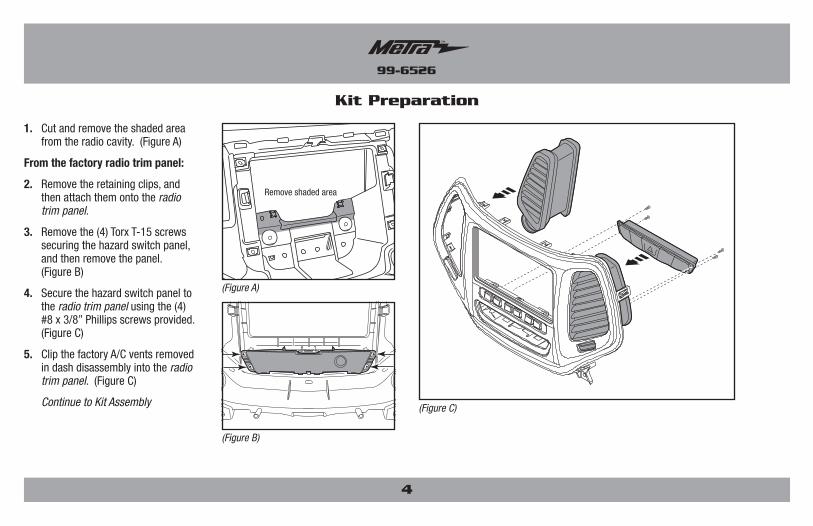
1. Cut and remove the shaded area from the radio cavity. (Figure A)
From the factory radio trim panel:
2. Remove the retaining clips, and then attach them onto the radio trim panel.
3. Remove the (4) Torx T-15 screws securing the hazard switch panel, and then remove the panel. (Figure B)
4. Secure the hazard switch panel to the radio trim panel using the (4) #8 x 3/8” Phillips screws provided. (Figure C)
5. Clip the factory A/C vents removed in dash disassembly into the radio trim panel. (Figure C)
Continue to Kit Assembly
Remove shaded area
(Figure A)
(Figure C)
(Figure B)
99-6526
5
Kit Assembly
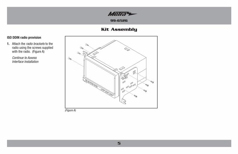
ISO DDIN radio provision
1. Attach the radio brackets to the radio using the screws supplied with the radio. (Figure A)
Continue to Axxess Interface Installation
(Figure A)

99-6526
6
Axxess Interface Installation
• Provides accessory power (12-volt 10-amp)• Retains R.A.P. (retained accessory power)• Retains the factory personalization menu and climate controls status• Can be used in amplified or non-amplified models• Provides NAV outputs (parking brake, reverse, and speed sense)• Prewired ASWC-1 harness included (ASWC-1 sold separately)• High level speaker input• Retains balance and fade• Ability to add aftermarket backup camera and additional video input• Retains factory screen• Micro “B” USB updatableATTENTION: The rear-view camera Input is used to display the climate control status and personalization menu. If the aftermarket radio does not have a screen with a rear-view camera Input, then there will be no visualization of the climate controls status and personalization menu, which makes adjusting the climate control impossible. An externally mounted screen could be substituted in this situation.
INTERFACE FEATURES
• Cutting tool • Crimping tool • Tape • Connectors (example: butt-connectors, bell caps, etc.)
TOOLS REQUIRED
• Axxess Interface • 18-pin harness with stripped leads• 6526 harness • 4-pin harness with stripped leads
INTERFACE COMPONENTS
Connections to be made
From the 18-pin harness with stripped leads to the aftermarket radio:• Connect the (2) Red wires to the accessory wire.
• Connect the Orange wire to both the illumination wire, AND the Orange wire on the 4-pin connector. (If the aftermarket radio has no illumination wire, just connect the (2) Orange wires together.)
• Connect the Blue/White wire to the amp turn on wire. (This wire must be connected to hear sound from the factory amplifier, if applicable.)
• Connect the White wire to the left front positive speaker output.
• Connect the White/Black wire to the left front negative speaker output.
• Connect the Gray wire to the right front positive speaker output.
• Connect the Gray/Black wire to the right front negative speaker output.
• Tape off and disregard the Brown, Green, Green/Black, Purple, and Purple/Black wires, they will not be used in this application.
Continued on the next page
99-6526
7
Connections to be made
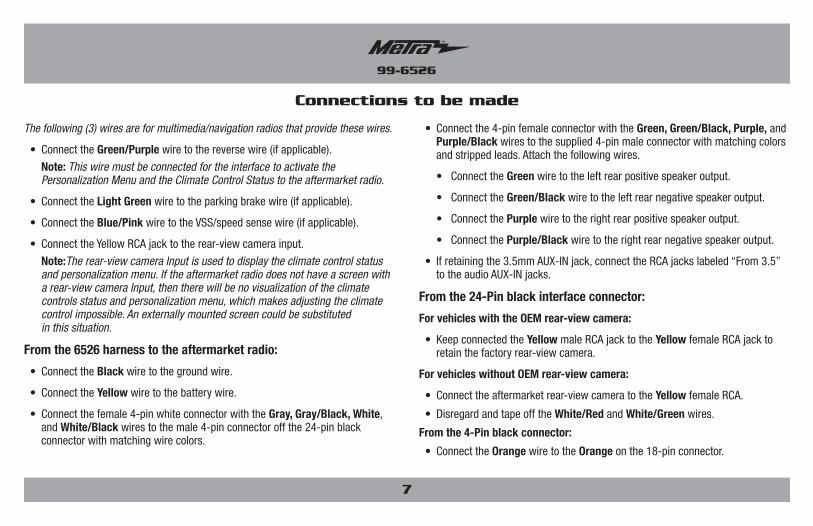
The following (3) wires are for multimedia/navigation radios that provide these wires.
• Connect the Green/Purple wire to the reverse wire (if applicable).
Note: This wire must be connected for the interface to activate the Personalization Menu and the Climate Control Status to the aftermarket radio.
• Connect the Light Green wire to the parking brake wire (if applicable).
• Connect the Blue/Pink wire to the VSS/speed sense wire (if applicable).
• Connect the Yellow RCA jack to the rear-view camera input.
Note:The rear-view camera Input is used to display the climate control status and personalization menu. If the aftermarket radio does not have a screen with a rear-view camera Input, then there will be no visualization of the climate controls status and personalization menu, which makes adjusting the climate control impossible. An externally mounted screen could be substituted in this situation.
From the 6526 harness to the aftermarket radio:
• Connect the Black wire to the ground wire.
• Connect the Yellow wire to the battery wire.
• Connect the female 4-pin white connector with the Gray, Gray/Black, White, and White/Black wires to the male 4-pin connector off the 24-pin black connector with matching wire colors.
• Connect the 4-pin female connector with the Green, Green/Black, Purple, and Purple/Black wires to the supplied 4-pin male connector with matching colors and stripped leads. Attach the following wires.
• Connect the Green wire to the left rear positive speaker output.
• Connect the Green/Black wire to the left rear negative speaker output.
• Connect the Purple wire to the right rear positive speaker output.
• Connect the Purple/Black wire to the right rear negative speaker output.
• If retaining the 3.5mm AUX-IN jack, connect the RCA jacks labeled “From 3.5” to the audio AUX-IN jacks.
From the 24-Pin black interface connector:
For vehicles with the OEM rear-view camera:
• Keep connected the Yellow male RCA jack to the Yellow female RCA jack to retain the factory rear-view camera.
For vehicles without OEM rear-view camera:
• Connect the aftermarket rear-view camera to the Yellow female RCA.
• Disregard and tape off the White/Red and White/Green wires.
From the 4-Pin black connector:
• Connect the Orange wire to the Orange on the 18-pin connector.

99-6526
8
Installing the Interface Final assembly
With the key in the off position:
1. Connect the 18-pin harness with stripped leads into the interface.
2. Connect the 6526 harness into the interface, and then into the vehicle.
3. Connect the 4-pin black harness into the keypad on the kit.
1. Locate the factory antenna connector in the dash, and complete all necessary connections to the radio. Metra recommends using the proper mating adapter from Metra.
Note: If using the ASWC-1 (sold separately), connect it after you program and test the 99-6526, with the key in the off position.
2. Before using the kit it must be initialized.
a. Start the vehicle.
b. With the vehicle running, turn the HVAC on, wait 5 seconds, turn the vehicle off, wait 5 seconds, and then turn the vehicle back on.
c. HVAC controls are now detected.
3. Test the radio and climate controls for proper operation.
4. Mount the completed assembly into the dash using the 99-6526 radio trim panel, and then reassemble the dash in reverse order of disassembly.

99-6526
9
Screen Operation
• Anytime the HVAC controls are pressed, the aftermarket radio will revert to rearview camera input and display the climate info.
• That screen will time out after 5-7 seconds if nothing else is changed.
• Press the menu button to force the HVAC controls to appear on screen.
• HVAC will stay on until Menu is pressed again
To change mode any time:
1. Press < or > arrow to move through the Mode options
To get into the Personalization menu:
1. Press “Enter” button to enter the menu.
2. Once in the menu, use up and down arrows to navigate through the menu and “Enter” to enter the settings
Note: Rear defrost, AC, and Recycle button does not cause the HVAC screen to appear. There are status lights on the buttons to indicate change.
99-6526
10
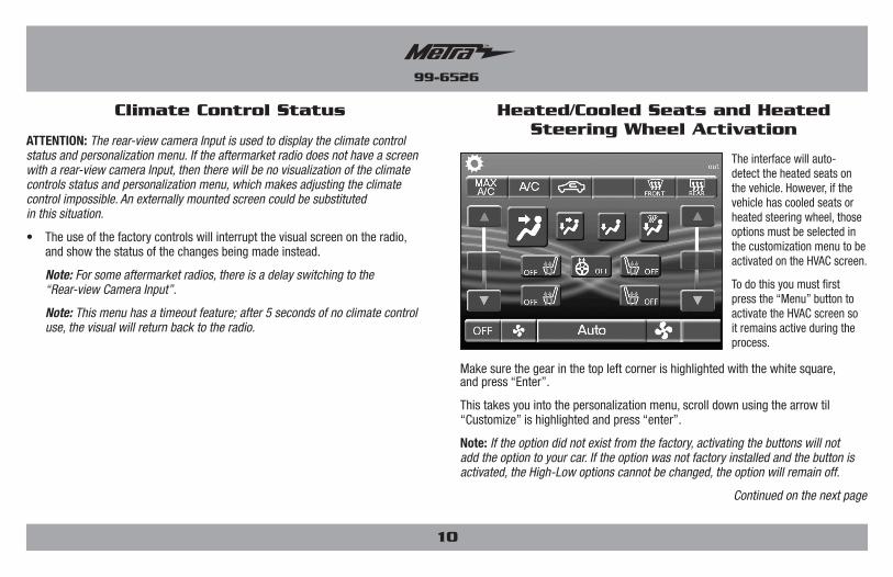
Climate Control Status Heated/Cooled Seats and Heated Steering Wheel Activation
ATTENTION: The rear-view camera Input is used to display the climate control status and personalization menu. If the aftermarket radio does not have a screen with a rear-view camera Input, then there will be no visualization of the climate controls status and personalization menu, which makes adjusting the climate control impossible. An externally mounted screen could be substituted in this situation.
• The use of the factory controls will interrupt the visual screen on the radio, and show the status of the changes being made instead.
Note: For some aftermarket radios, there is a delay switching to the “Rear-view Camera Input”.
Note: This menu has a timeout feature; after 5 seconds of no climate control use, the visual will return back to the radio.
The interface will auto-detect the heated seats on the vehicle. However, if the vehicle has cooled seats or heated steering wheel, those options must be selected in the customization menu to be activated on the HVAC screen.
To do this you must first press the “Menu” button to activate the HVAC screen so it remains active during the process.
Make sure the gear in the top left corner is highlighted with the white square, and press “Enter”.
This takes you into the personalization menu, scroll down using the arrow til “Customize” is highlighted and press “enter”.
Note: If the option did not exist from the factory, activating the buttons will not add the option to your car. If the option was not factory installed and the button is activated, the High-Low options cannot be changed, the option will remain off.
Continued on the next page

99-6526
11
If heated seats were detected the first line should already be checked.
To select cooled seats scroll down and press “enter” once to select cooled seats, then once more to activate the cooled seats control buttons.
This will cause the screen to revert to the HVAC screen to verify the buttons have been activated.
If heated steering wheel is present, repeat the steps above but double click heated steering wheel.
After the selection process is complete the key MUST BE cycled for proper operation of the buttons.
Press the “Menu” button to activate the HVAC screen
Press the down arrow till the button you wish to activate is highlighted, and press “Enter”.
If the heated/cooled seats button is pressed multiple times, the options change from Off to High to Low.
The heated steering wheel option only have an On and Off option.
Note: Similar to the factory operation, the heated/cooled seats and heated steering wheel will be able to be activated while the HVAC is turned off. The same operation procedure applies.
Heated/Cooled Seats and Heated Steering Wheel Activation

METRA - The World’s best kits ® metraonline.com © COPYRIGHT 2018 METRA ELECTRONICS CORPORATION
REV.
4/2
6/20
18
INST
99-6
526
KNOWLEDGE IS POWEREnhance your installation and fabrication skills by enrolling in the most recognized and respected mobile electronics school in our industry.Log onto www.installerinstitute.com or call 800-354-6782 for more information and take steps toward a better tomorrow.
®
Metra recommends MECP certified technicians
Installation instructions for part 99-6526
®
IMPORTANTIf you are having difficulties with the installation of this product, please call our Tech Support line at 1-800-253-TECH. Before doing so, look over the instructions a second time, and make sure the installation was performed exactly as the instructions are stated. Please have the vehicle apart and ready to perform troubleshooting steps before calling.
Indice
METRA - The World’s best kits ® metraonline.com
REV.
4/2
6/20
18
INST
99-6
526
Instrucciones de instalación para la pieza 99-6526
®
¡PRECAUCIÓN! Todos los accesorios, interruptores, paneles de con-troles de clima y especialmente las luces del indicador de las bolsas de aire deben estar conectados antes ciclar la ignición. Además, no quite el radio de fábrica con la llave en la posición o de encendido ni con el vehículo funcionando.
© COPYRIGHT 2018 METRA ELECTRONICS CORPORATION
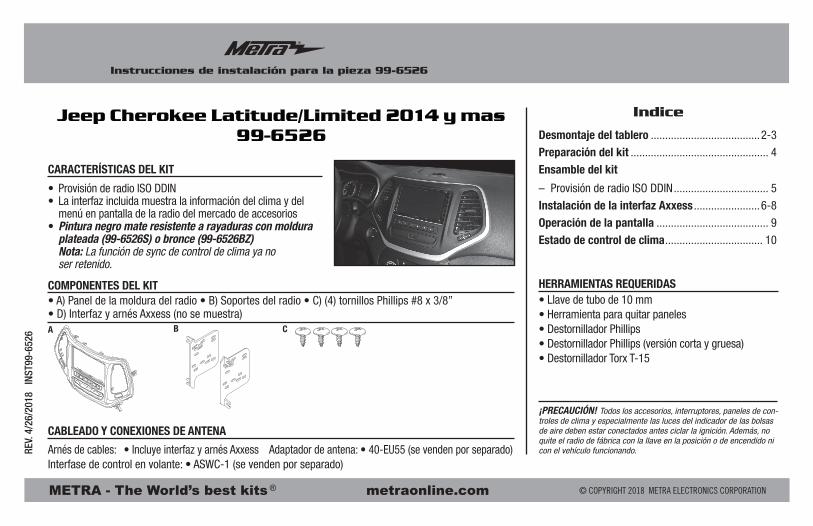
• Provisión de radio ISO DDIN• La interfaz incluida muestra la información del clima y del menú en pantalla de la radio del mercado de accesorios• Pintura negro mate resistente a rayaduras con moldura plateada (99-6526S) o bronce (99-6526BZ) Nota: La función de sync de control de clima ya no ser retenido.
• A) Panel de la moldura del radio • B) Soportes del radio • C) (4) tornillos Phillips #8 x 3/8” • D) Interfaz y arnés Axxess (no se muestra)
CARACTERÍSTICAS DEL KIT
COMPONENTES DEL KIT
CABLEADO Y CONEXIONES DE ANTENA
Arnés de cables: • Incluye interfaz y arnés Axxess Adaptador de antena: • 40-EU55 (se venden por separado)Interfase de control en volante: • ASWC-1 (se venden por separado)
Jeep Cherokee Latitude/Limited 2014 y mas99-6526
• Llave de tubo de 10 mm• Herramienta para quitar paneles• Destornillador Phillips• Destornillador Phillips (versión corta y gruesa)• Destornillador Torx T-15
HERRAMIENTAS REQUERIDAS
A CB
Desmontaje del tablero ......................................2-3
Preparación del kit ................................................ 4
Ensamble del kit
– Provisión de radio ISO DDIN ................................. 5
Instalación de la interfaz Axxess .......................6-8
Operación de la pantalla ....................................... 9
Estado de control de clima .................................. 10

99-6526
Desmontaje del tablero
2
1. Desenganche, desconecte y quite el panel del control de clima. (Figura A)
2. Quite los (2) tornillos Phillips del panel de la moldura del radio y luego desconecte y retire el panel. (Figura B)
3. Soltar y retirar los / C respiraderos A y ahorrar para el montaje del kit.
Continua en la siguiente pagina
(Figura A) (Figura B)

99-6526
3
3. Quite los (4) tornillos Phillips que sujetan el radio y luego desconecte y quite el radio. (Figura C)
4. Abra la puerta de la cavidad en la parte superior del tablero, quite el revestimiento de caucho y luego quite el (1) tornillo Phillips expuesto.
5. Quite el soporte de apoyo del radio de metal:
a. Quite los (2) pernos de 10 mm visibles desde la parte delantera. (Figura D)
b. From the inside of the radio cavity, remove (2) Phillips screws using a short stubby Phillips screwdriver. (Figura D)
c. Remove the support from the radio cavity.
Continúe con la Preparación del Kit
(Figura C) (Figura D)
Desmontaje del tablero
99-6526
4
Preparación del kit
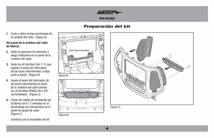
1. Corte y retire el área sombreada de la cavidad del radio. (Figura A)
Del panel de la moldura del radio de fábrica:
2. Quite los ganchos de retención y luego colóquelos en el panel de la moldura del radio.
3. Quite los (4) tornillos Torx T-15 que sujetan el panel del interruptor de las luces intermitentes y luego quite el panel. (Figura B)
4. Sujete el panel del interruptor de las luces intermitentes al panel de la moldura del radio usando los (4) tornillos Phillips #8 x 3/8” suministrados. (Figura C)
5. Cortar las rejillas de ventilación de la fábrica de A / C retirados en el desmontaje de instrumentos en el panel de ajuste de radio. (Figura C)
Continúe con el Ensamble del Kit
Quite área sombreada
(Figura A)
(Figura C)
(Figura B)

99-6526
Ensamble del kit
Provisión de radio ISO DDIN
1. Una los soportes del radio al radio usando los tornillos que se (Figura A)
Continúe con la instalación de la interfaz Axxess
(Figura A)
5

99-6526
6
Instalación de la interfaz Axxess
• Provee corriente de accesorio (12 voltios 10 amperes)• Retiene R.A.P. (corriente de accesorio retenida)• Retiene el menú de personalización de fábrica y el clima controla el estado• Puede ser utilizado en los modelos amplificados o no amplificados• Proporciona salidas de NAV (freno de mano, reversa y sensor de velocidad)• Arnés ASWC-1 pre cableado incluido (el ASWC-1 se vende por separado)• Entrada de bocina de alto nivel• Retiene el balance y la intensidad• Posibilidad de añadir cámara de retroceso del mercado de accesorios y
entrada de vídeo adicional• Retiene la pantalla de la fábrica• Actualizable por micro “B” USBATENCIÓN: La cámara de visión trasera de entrada se utiliza para mostrar el estado de control climático y menú de personalización. Si la radio no original no tiene una pantalla con una cámara de visión trasera de entrada, entonces no habrá ninguna visualización del menú de estado de control de temperatura y la personalización, lo que hace que el ajuste del climatizador imposible. Una pantalla montada en el exterior podría ser sustituido en esta situación.
CARACTERÍSTICAS
• Herramienta para cortar • Pelacables • Cinta • Conectores (ejemplo: conectores de extremo, de campana, etc.)
HERRAMIENTAS REQUERIDAS
• Interfaz Axxess • Arnés de 18 pins con conectores pelados• Arnés 6526 • Arnés de 4 pins con conectores pelados
COMPONENTES DE LA INTERFAZ
Conexiones que se deben hacer
Del arnés de 18 pins con conectores pelados al radio de mercado secundario:• Conecte los (2) cables Rojos al cable de accesorios.
• Conecte el cable Anaranjado al cable de iluminación Y el cable anaranjado al conector de 4 pins. (Si el radio de mercado secundario no tiene cable de iluminación, sólo tiene que conectar los cables (2) Anaranjados juntos.)
• Conecte el cable Azul/Blanco al cable de encendido del amplificador. (Este cable debe estar conectado para escuchar sonido del amplificador de fábrica).
• Conecte el cable Blanco a la salida positiva de la bocina izquierda delantera.
• Conecte el cable Blanco/Negro a la salida negativa de la bocina izquierda delantera.
• Conecte el cable Gris a la salida positiva de la bocina derecha delantera.
• Conecte el cable Gris/Negro a la salida negativa de la bocina derecha delantera.
• Encinte e ignore los cables Marrón, verde,verde/negro, púrpura y púrpura/negro, no se utilizarán en esta aplicación.
Continua en la siguiente pagina

99-6526
Los siguientes (3) cables son para radios con multimedios/navegación que incluyen estos cables.
• Conecte el cable Verde/Púrpura al cable de reversa (si aplica).
Nota: Este cable debe conectarse a la interfaz para activar el menú de personalización y el régimen de control climático para la radio no original.
• Conecte el cable Verde Claro al cable de freno de mano (si aplica).
• Conecte el cable Azul/Rosa al cable VSS o del sensor de velocidad (si aplica).
• Connect the Yellow RCA jack to the rear-view camera input. Nota: La cámara de visión trasera de entrada se utiliza para mostrar el estado de control climático y menú de personalización. Si la radio no original no tiene una pantalla con una cámara de visión trasera de entrada, entonces no habrá ninguna visualización del menú de estado de control de temperatura y la personalización, lo que hace que el ajuste del climatizador imposible. Una pantalla montado en el exterior podría ser sustituido en esta situación.
Desde el arnés 6525 al radio de mercado secundario:
• Conecte el cable Negro al cable de tierra.
• Conecte el cable Amarillo al cable de la batería.
• Conectar el conector hembra Blanco de 4 pines con el Gris, Gris/Negro, Blanco, Blanco/Negro cables al conector macho de 4 clavijas del conector negro de 24 polos con colores de los cables a juego.
• Conectar el conector hembra de 4 pins con el Verde, Verde/Negro, Púrpura, y los cables Negro/Púrpura al conector macho de 4 pines suministrado con colores a juego y los cables pelados. Adjuntar los siguientes cables.
• Conecte el cable Verde a la salida positiva de la bocina izquierda trasera.
• Conecte el cable Verde/Negro a la salida negativa de la bocina izquierda trasera.
• Conecte el cable Púrpura a la salida positiva de la bocina derecha trasera.
• Conecte el cable Púrpura/Negro al cable de la salida negativa de la bocina derecha trasera.
• Si conserva la toma AUX-IN de 3,5 mm, conecte los conectores RCA marcadas “A partir de 3,5” a las tomas de audio AUX-IN.
Del conector de interfaz negro de 24 pins:Para los vehículos con la cámara de visión trasera OEM:
• Manténgase conectado el conector RCA macho Amarillo al conector hembra RCA Amarillo para retener la cámara de fábrica retrovisor.
Para los vehículos sin la cámara de visión trasera OEM:
• Conectar el mercado de accesorios de la cámara de visión trasera a la hembra RCA Amarillo.
• El desconocimiento y la cinta fuera del blanco / rojo y blanco / verde cables.
Del conector negro de 4 pins:
• Conecte el cable anaranjado al cable anaranjado/blanco en el conector de 18 pins.
Conexiones que se deben hacer
7

99-6526
8
Instalación de la interfaz
Con la llave en la posición de apagado:
1. Conecte el arnés de 18 pins con cables pelados en la interfaz.
2. Conecte el mazo de 6526 en la interfaz, y luego en el vehículo.
3. Conecte el arnés negro de 4 pins en el teclado numérico del kit.
Ensamble final
1. Localice el conector de la antena de fábrica en el tablero y realice todas las conexiones necesarias al radio. Metra recomienda el uso de un adaptador adecuado de acoplamiento de Metra.
Nota: Si va a utilizar el ASWC-1 (se vende por separado), conéctelo después de programar y probar el 99-6526 con la llave en la posición de apagado.
2. Antes de utilizar el kit debe ser inicializado.
a. Arrancar el vehículo.
b. Con el vehículo en marcha, gire el HVAC, espere 5 segundos, apague el vehículo, esperar 5 segundos, y luego girar el vehículo en.
c. Controles de HVAC ahora se detectan.
3. Pruebe que el radio y los controles del clima operen adecuadamente.
4. Monte el ensamble terminado en el tablero usando el panel de la moldura del radio 99-6526, y después vuelva a armar el tablero al revés de como lo desarmó.

99-6526
9
Operación de la pantalla
• Cada vez que se presionen los controles de clima, el radio de mercado secundario se revertirá a la cámara retrovisora y mostrará la información del clima.
• Esa pantalla desaparecerá después de 5-7 segundos si no cambia ningún otro ajuste.
• Presione el botón de menú para que aparezcan los controles de clima en la pantalla.
• El clima permanecerá activado hasta que el botón de menú se presione de nuevo
Para cambiar el modo en cualquier momento:
1. Presione la flecha < o > para avanzar por las opciones de modo
Para ingresar al menú de personalización:
1. Presione el botón “Enter” para ingresar al menú.
2. Una vez en el menú, use las flechas de arriba y abajo para navegar por el menú y presione “Enter” para ingresar los ajustes
Nota: El botón de desempañador trasero, aire acondicionado y reciclado no ocasiona que aparezca la pantalla del clima. Hay luces de estado en los botones para indicar cambios.

99-6526
Estado de control de clima
ATENCIÓN: La entrada de la cámara retrovisora se utiliza para mostrar el estado de control de clima y el menú de personalización. Si el radio de mercado secundario no tiene una pantalla con una entrada de cámara retrovisora, entonces no se visualizará el estado de control de clima y menú de personalización, lo que hace que sea imposible ajustar el control de clima. Una pantalla montada externamente podría utilizarse en esta situación.
• El uso de los controles de clima interrumpirá la pantalla visual del radio y mostrará el estado de los cambios que se están realizando.
Nota: Para algunos radios de mercado secundario, existe un retardo al cambiar a “entrada de cámara retrovisora”.
Note: Este menú tiene una función de tiempo de espera; después de 5 segundos de no utilizar el control de clima, la imagen volverá de nuevo al radio.
10
Asientos con calefacción/refrigeración y calefacciónActivación del volante
La interfaz detectará automáticamente los asientos con calefacción en el vehículo. Sin embargo, si el vehículo tiene asientos refrigerados o volante con calefacción, esas opciones se deben seleccionar en el menú de personalización para que se activen en la pantalla de HVAC.
Para hacer esto, primero debe presionar el botón “Menú” para activar la pantalla HVAC para que
permanezca activa durante el proceso.
Asegúrese de que el engranaje en la esquina superior izquierda esté resaltado con el cuadrado blanco, y presiona “Enter”.
Esto lo lleva al menú de personalización, desplácese hacia abajo usando la flecha hasta que se resalte “Personalizar” y presione “enter”.
Nota: Si la opción no existió de fábrica, al activar los botones no se agregará la opción a su automóvil. Si la opción no se instaló de fábrica y el botón está activado, las opciones Alto-Bajo no se pueden cambiar, la opción permanecerá desactivada.
Continua en la siguiente pagina

99-6526
11
Asientos con calefacción/refrigeración y calefacciónActivación del volante
Si se detectaron asientos con calefacción, la primera línea ya debería estar marcada.
Para seleccionar los asientos refrigerados, desplácese hacia abajo y presione “enter” una vez para seleccionar los asientos refrigerados, luego
una vez más para activar los botones de control de los asientos refrigerados.
Esto hará que la pantalla vuelva a la pantalla de HVAC para verificar que los botones hayan sido activados.
Si hay volante con calefacción, repita los pasos anteriores, pero haga doble clic en el volante con calefacción.
Una vez que se completa el proceso de selección, la tecla DEBE estar ciclada para el correcto funcionamiento de los botones.
Presione el botón “Menú” para activar la pantalla HVAC
Presione la flecha hacia abajo hasta que se resalte el botón que desea activar y presione “Entrar”.
Si el botón de los asientos con calefacción / refrigeración se presiona varias veces, las opciones cambian de Apagado a Alto a Bajo.
La opción del volante con calefacción solo tiene una opción de encendido y apagado.
Nota: De forma similar a la operación de fábrica, los asientos con calefacción / refrigeración y el volante con calefacción podrán activarse mientras la HVAC esté apagada. Se aplica el mismo procedimiento de operación.

REV.
4/2
6/20
18
INST
99-6
526
METRA - The World’s best kits ® metraonline.com © COPYRIGHT 2018 METRA ELECTRONICS CORPORATION
KNOWLEDGE IS POWEREnhance your installation and fabrication skills by enrolling in the most recognized and respected mobile electronics school in our industry.Log onto www.installerinstitute.com or call 800-354-6782 for more information and take steps toward a better tomorrow.
®
Metra recomienda técnicos con certificación del Programa de Certificación en Electrónica Móvil (Mobile Electronics Certification Program, MECP).
EL CONOCIMIENTO ES PODERMejore sus habilidades de instalación y fabricación inscribiéndose en la escuela de dispositivos electrónicos móviles más reconocida y respetada de nuestra industria. Regístrese en www.installerinstitute.com o llame al 800-354-6782 para obtener más información y avance hacia un futuro mejor.
Instrucciones de instalación para la pieza 99-6526
®
IMPORTANTESi tiene dificultades con la instalación de este producto, llame a nuestra línea de soporte técnico al 1-800-253-TECH. Antes de hacerlo, revise las instrucciones por segunda vez y asegúrese de que la instalación se haya realizado exactamente como se indica en las instrucciones. Por favor tenga el vehículo desarmado y listo para ejecutar los pasos de resolución de problemas antes de llamar.