Embed Size (px)
Citation preview
Formal Aspects of Computing (1999) 11: 244–271c© 1999 BCS Formal Aspects
of Computing
A Minimal Graphical User Interface for the JapeProof Calculator
Richard Bornat1 and Bernard Sufrin2
1Department of Computer Science, Queen Mary and Westfield College, University of London, UK2Programming Research Group, University of Oxford, Oxford, UK
Keywords: GUI proof; Proof calculator
Abstract. GUI design isn’t simply a matter of putting a nice front-end on acapable program. It requires thought about the way in which people might beexpected to use a system, and investigation of the ways that they actually use it.Jape’s GUI has been designed to be as simple as possible, so that it will not get inthe way of the business of proof. It is designed to be minimal in the informationthat it displays and the gestures that it requires from the user. In this paper weintroduce and give a rationale for the design of Jape’s user interface, then notesome of its drawbacks.
1. Introduction
Computers are very good at formal calculations. In fact, they are good for nothingelse. Logic is an utterly formal business, so computers ought to be very good atdoing logic. Indeed they are, but they aren’t, yet, very good at doing logic for us:solving interesting formal problems on our terms. Some of the problem is in theformalisms, but there is also a mismatch between the characteristics of machinesand the nature of human reasoning. We haven’t built computing systems thatare very good at communicating formalisms to people or interpreting people’sintentions about formal calculations. In other words, there aren’t yet formalreasoning systems with good user interfaces.
Most of the interest in user interfaces at present is in graphical user interfaces(GUIs). Most users of most computer systems communicate with them through
Correspondence and offprint requests to: Richard Bornat, Department of Computer Science,Queen Mary and Westfield College, University of London, London E1 4NS, UK. Email:[email protected]; http://www.dcs.qmw.ac.uk/∼richard

A Minimal Graphical User Interface for the Jape Proof Calculator 245
the same kind of GUI. The universal vocabulary of point-and-click and press-and-drag within the 21
2D virtual desktop is expressive enough to allow the ordinaryperson to use a computer to do useful work, and has been the catalyst that hasencouraged computing to spread to almost every corner of life.
Such is the public enthusiasm for GUIs that every program designer is temptedto join in. But there are at least two distinct GUI design traditions one mightjoin. One uses graphics to communicate more information about the workingsof a program and uses menus and buttons to give more immediate access to theoperation of the machinery. In that tradition the ideal is a spaceship cockpit,covered with dials and knobs and switches: everything that can be measured isdisplayed; everything that can be altered is controllable. Experts can discoveranything and modify everything, provided only that they know where to look andwhat to touch. By contrast the other tradition attempts to use the immediacy ofgraphics and the physicality of mouse gesturing to make communication with aprogram as effortless as possible. Here the ideal is a wristwatch, a device with fewcontrols and so simple to use that its users don’t glimpse its internal complexity –in Norman’s phrase [Nor98] quiet, invisible, unobtrusive; the aim is to make themachine invisible.
Though the two traditions use the same display technology and the samegesturing mechanisms, it’s difficult to justify one to the adherents of the other. Ina nutshell, the first tradition is technology-oriented, the second is task-oriented.Space cadet or watchmaker, Xemacs or SimpleText: the products of one tradition,even the design aims of its practitioners, will be rejected within the other.
This paper is written from within the second tradition. So it is not about goodways to deliver functionality or neat mechanisms to fit GUIs to high-poweredmachinery. It is not even about a new logical approach which makes design ofa GUI a triviality. It is, rather, about the subtle design choices that have to bemade to produce a program which always does what its users expect it to do,even when they don’t know quite what to expect.
This paper is not simply about a GUI, but about a program and its GUItogether. Supporting the GUI is the very purpose of the program’s existence.Jape is a proof calculator: a program which supports the human-led discovery ofproofs and their presentation in readable form. As a calculator for a particularproof in a particular logic, it does little more than apply the rules of inference ofthat logic under its user’s direction, and show the result in an appropriate form.The logical calculations are performed by the proof engine; the user-interfaceinterprets users’ gestures and displays proofs, partial proofs or proof attempts.
One particular GUI design principle that we have struggled to live up to isminimalism: to give our users what they need within as small a visual and gesturalspace as possible. There are no multiple views of the proof, no summaries ofinternal state, no visible proof history, hardly any dialogue boxes. We believethat unity of design between engine and interface, and an explicit commitment tominimalism, makes our work distinctive within the community of those trying tobring the benefits of graphical user interaction to formal reasoning by computer.
In our tradition the highest praise we can receive from a user is that themechanism seems very simple, that there seems to be nothing substantial there.When people have that reaction to Jape, we are delighted. There is actually quitea lot there – about twenty thousand lines of SML code in the engine, and anotherfew thousand in the interface, all beavering away trying to be invisible. So if youthink that this paper goes into minute detail about not very much at all, there isa sense in which you will be right and we will be satisfied.

246 R. Bornat and B. Sufrin
GUI development is always experimental, and a developer is always focusingon the next possible improvement. Nobody has managed yet to make a GUIdisappear, and Jape’s is by no means invisible. In this paper, therefore, we havegone beyond a description of what has been achieved to discuss the ways inwhich we have failed to achieve our goals and what lessons we might draw fromthose failures. That discussion goes into minute details, but such is the nature ofGUI research.
Since this is a paper about user interfaces, and not about theorem proving, theexamples used in illustrations are just large enough to make each of our pointsabout display and gesture. As a result they are logically trivial, but that should notbe taken to imply that users of Jape must restrict themselves to trivial problems.Space limitations have prevent us discussing every aspect of Jape’s GUI here. Inparticular we have omitted detailed discussion of the way in which the enginedisplays proofs so that they are easy on the eye. All the proof illustrations aretaken from the displays produced by Jape’s GUI under MacOS; similar displaysare produced under UNIX.
2. The Watchmaker’s Creed
In the space cadet tradition a graphical user interface (GUI) is a collectionof buttons, menus and windows designed to command a computing device.Commands that might once have had to be laboriously constructed at thekeyboard can be communicated with a single click of the mouse. In that traditionthe purpose of a GUI is to reduce the physical effort required to issue a command.It would seem to follow that the more buttons, menus and windows the fewer themouse clicks and the better the user experience.
The watchmaker’s view of a computing system is as an aid to carrying out atask, and the purpose of the GUI is to facilitate task activity. But the existence ofthe GUI itself creates an additional task, the task of understanding and controllingthe interface. That task ought surely to require as little effort as possible. In mostcomputer-aided work it is the cognitive effort of carrying out the underlying taskthat should dominate, and the cognitive distraction of controlling the interfacethat must be minimised1.
Interaction with a computing system has something of the quality of a game:we have to guess what state the system is in, and we must base our actions onthat guess. If our guess is right, we have a chance that the command we choosewill have the effect we desire. If we guess wrongly, then almost anything canhappen. It’s impossible to interact with a black box unless you can concentratehard enough to sustain a mental image of what’s inside, and that concentrationdistracts you from the task in hand. Every large computer program is somethingof a black box and nobody at all can understand, in detail, just what happensinside it. We all get by with approximations, with partial mental models of aprogram’s state. In the best case our approximations are useful abstractions ofreality.
The best interactive computing systems, therefore, are designed so that thereis a model of their working which is both faithful to reality and easy to grasp.
1 We include perceptual effort as part of cognitive effort, for the purposes of our discussion.

A Minimal Graphical User Interface for the Jape Proof Calculator 247
Promoting a simple user’s mental model [NeL95] of its operation is the most im-portant technique for reducing the cognitive load imposed by use of a computingdevice. The first step in GUI design, therefore, is to invent a user’s mental modelthat can be effectively promoted by the behaviour of the GUI. Only later is ituseful to think of ways in which the machine can simulate the operations of thechosen model. That is a very strong constraint on the design of the behind-the-scenes mechanism: so strong, indeed, that it’s often useless to graft a GUI to anexisting application, because the application’s mechanisms are rarely a good fitwith the mental model. It is the user’s mental model that’s central to GUI design,and not the engine behind the scenes. It dominates even the definition of theuser’s task, because sometimes the choice of mental model helps to redefine thetask.
In short, we use computers to save ourselves effort, so they shouldn’t cause usto do unnecessary mental or physical work. A badly-designed GUI can increasethe physical difficulty of a task, and it’s as easy to get RSI from a mouse as froma keyboard. At this point watchmakers have some common ground with spacecadets. Minimising physical effort is a good idea when it minimises cognitiveeffort. It is physically easier to point to a file on a desktop than to type itsdirectory-tree filename; it’s physically easier to click a button than type the nameof a command. But reducing the physical effort of using a GUI is only worthwhileif the cognitive effort is correspondingly low. If not – if in order to make onemouse click you first have to search with your eyes through tens of icons that litteryour desktop, or hundreds of buttons in a toolbar2 – then minimising physicaleffort is a bad idea.
It is often asserted that novices and experts have very different GUI needs.Certainly, novices have particular requirements: it has to be possible to makeuse of the GUI without knowing how to use all of its facilities, and it has tobe possible to explore its facilities without risk. Experts, paradoxically, are lessdemanding: they want to get straight to the point, and are prepared to expendeffort to learn about a GUI’s obscure shortcuts, bells and whistles. Few will knowit all, though, and experts too can benefit from risk-free exploration. It seemsobvious to us that, other things being equal, experts benefit if the cognitive loadof carrying out a task is reduced; it is by no means obvious to us that they mustforever be condemned to be space cadets.
None of this discussion is new. The basic principles of GUI design havebeen evident for over twenty years, and are well propounded elsewhere [NeS79,NeL95, Thi90, App90]. It is evident, however, that they are not well understoodeverywhere, and we put Jape forward as an example of how they may be appliedin the particular problem area of computer-assisted formal proof.
3. Jape’s Task and User’s Mental Model
Our intention was to support reflective exploration [MeH96], helping our usersto find out about a logic by developing proofs. We haven’t chosen to support thetheorem-proving task, which is in principle to find that there is a proof. Nor havewe aimed to support the proof-checking task, which is to decide whether or not
2 ‘Hundreds’ is not an exaggeration. There are 271 on-screen iconised buttons simultaneously availablein Microsoft Word 97, with uncounted others behind the scenes in pull-down menus and tabbeddialogues.

248 R. Bornat and B. Sufrin
a given text represents a proof. Had we chosen either we would probably haveconstructed quite a different GUI.
A user’s mental model of a computing system is easiest to grasp if it hasalready occurred to the user beforehand, and it is easiest to work with if thesystem shows a picture of the entire state of the model. Mental models whichappeal to paper-and-pencil analogues are, therefore, very popular. In Jape wedecided at the outset to support the construction of tree and box-and-line proofslike those illustrated in this paper. In order to support exploration we wanted todisplay all the intermediate stages of proof construction: most of the illustrationsbelow are of partial proofs, proofs in mid-construction, proof attempts. We wantedto do for pencil-and-paper proofs what word processors do for pencil-and-papertexts: take over the bookkeeping, keep everything shipshape, but don’t interferein the decision-making process. Because it suited the needs of both ends of thenovice/expert spectrum, we designed Jape to be generic in the logics it supports.
In the early stages of the evolution of our design each proof step in Japeconsisted of the application of a single inference rule. That was convenient forproof novices and for education: our aim was to encourage reflection about themeanings of inference rules, and each tiny step is in principle worthy of reflection3.But that is not the only way to use a GUI like Jape’s. A display of a partialproof allows important decisions to be taken in the light of progress so far. It isunlikely that users will always perform best when they can only see the bit of aproblem which a theorem prover considers must be worked on next – that is, onetip of an otherwise invisible tree. On the other hand, it is essential that they don’tsee more than they need to see in order to make an informed choice. Much ofour design effort has been directed to refining the logic encoder’s control4 overwhat is seen in the display and how gestures towards the display are interpreted.
4. Internal vs External Representation
Because the only test of a GUI is the satisfaction of its human users, GUIresearch and development must be an experimental business. The mechanism ofinteraction between user and machine can be designed as carefully as may be, butonly experiment will tell if it is effective. In Jape’s case the form of the displayhas been a matter of continual experiment. We have searched for ways to pushthe display closer to what the user wants to see – driven all the time by therequirements of our users – without losing contact with the machine’s internalmechanisms. Over the years we have gone from initial experiments with thedisplay of inference trees to development of a treatment of transitive equationalreasoning. The journey has taken us far from the conventional all-introductionbackward-reasoning style of interactive theorem proving.
Internally Jape uses an inference tree of hypothetical judgements and appliesinference rules structurally similar to those of the sequent calculus. Nothingelse seems to be general enough to support a wide range of logics, nor sostraightforward to implement. But the display does not always show a tree: for
3 At the time of writing there is a research project underway to investigate the effectiveness of Japein promoting visualisation of proofs. We expept that a by-product of that project will be a detailedcritique of Jape’s shortcomings as an educational tool, which we will use to improve its design.4 Jape has two classes of users. The end user, the prover, makes proofs in a logic. The logic encodertranscribes a logic and programs the interaction to suit that logic.

A Minimal Graphical User Interface for the Jape Proof Calculator 249
example, in Fig. 14a below the proof steps look like equational rewrites, notinference steps. The whole tool – engine plus interface – must internally supportwhat is supportable, externally display what is palatable, interpret gestures at thedisplay in terms of the components of the inference tree, and always keep thetwo in step.
The user’s mental model which we encourage is that the proof that you seeis what the machine is working on. You make progress by pointing to places orparts of the proof and indicating what you wish to happen. We encourage, byusing the slogan “point to the thing you want to work on”, the idea that a proofstep transforms proof components, producing as a result other components.
Slogans which explain what a tool can do may aid its usability by altering theuser’s perception of the task, but when the distance between an internal realityand external presentation becomes too great, something will give way and theillusion will break down. We think it would be impossibly difficult to build thekind of GUI described here if the underlying mechanism didn’t have a proof datastructure at its centre; reconstructing the proof at each stage would be far toodifficult. For similar reasons, we have chosen to represent logics without significantencoding. In one respect this makes Jape an unusual proof tool: it representsprovisos – extra-logical side-conditions on proof steps – literally, rather thanSkolemising or otherwise encoding them. That makes for relative inefficiency,because the tool must continually interpret the provisos during a proof, but italso makes it possible to display the proof in terms of the pencil-and-paper logicand therefore the user’s mental model.
Jape doesn’t always show all of a proof to the user, but if it is to be asound logical calculator each visible proof step must be made up from a numberof sound primitive steps. We preserve soundness by ensuring that the internalrepresentation of a proof is at the level of inference rule applications. To supporta form of display which shows larger visible steps, the logic encoder is given agood deal of control over the way in which the logical proof tree is projectedonto the display. External brevity can be achieved even though the tool’s internalrecord is prolix (for example, Fig. 8 vs Fig. 9).
5. Simplicity, Quietness, Minimalism and Passivity
The ideal, when supporting a user’s mental model of pencil-and-paper activity,is a tool which seems to do just what pencil and paper do, which is merely torecord the user’s activity. We aim to give our users an experience in which thedisplay shows them the proof that they are thinking about, the gestures towardsthe display don’t need to be explained, and the steps in development seem justthose which would have been made without the tool’s assistance. Our job is thedesign of simplicity.
Since we can’t build intelligent machinery, our approach to the design ofsimplicity has been to design a quiet interface: one whose activity doesn’t impingeon the user’s consciousness too often. But quietness is a slogan, not a designmethod, and to achieve it we have imposed on ourselves a discipline of minimalism.We want to present an interface in which it is possible to work with a minimalvocabulary of gestures, and with no more displayed information than is necessaryto carry out the pencil-and-paper proof task. We’ve constrained ourselves to usethe vernacular of modern GUIs – point-and-click with the mouse, take commandsfrom menus, a little press-and-drag selection, some drag-and-drop where it fits our

250 R. Bornat and B. Sufrin
Fig. 1. Some rules of a natural deduction logic rendered for Jape.
purpose. We show the user only the proof, and nothing of the internal workingsof the tool.
Quietness is a requirement derived, we believe, from the nature of the task:logical proof is intrinsically complicated and the interface should not distractthe user’s attention. Minimalism is a route to quietness. Passivity of the minimalinterface [Thi90] is a design decision which supports the user’s mental model thatthe tool is a calculator, something that makes useful formal manipulations butdoesn’t offer advice.
The user as encoder has not been neglected: Jape has a programming notationin which systems of inference rules can be described and through which thedetails of the graphical interface may be controlled. We anticipate that many ofour encoders will be novice logicians and will therefore need a quiet interface oftheir own. We believe that in the matter of encoding logic rules our interface isquieter than most: Jape’s encoding of an inference rule is little more than a lineartranscription, as illustrated in Fig. 15.
6. The Display
The main internal data structure of Jape is the inference tree. Inference treescan easily be directly represented on a computer screen: for example, see Fig. 3.Inference rule steps, from valid tree to valid tree, are directly implementedon the internal data structure. This provides a straightforward guarantee ofcorrespondence to a logic: the tree is one produced by the application of inferencerules of that logic. A natural starting point for a proof tool like Jape, then, is thedirect display of the internal tree.
But why show the whole tree? There are lots of circumstances where someparts of a proof tree, however necessary for correspondence to the logic, areirrelevant to the prover. If a sub-proof is carried out automatically, for example,
5 The transcription of natural deduction rules into a sequent notation as in Fig. 1 is fairly standard,but for those not used to the notation some points are worth noting. First, hypothesis formulae ina rule or a problem statement are written on the left-hand side of the segment, before the turnstilesymbol # (for example see the → -l rule) while conclusion formulae are written on the right-handside. In the rest of our discussion we normally describe formulae as left-side or right-side ratherthan hypothesis or conclusion. In the box-and line presentation, left-side formulae are displayed onhypothesis/premise/assumption lines.

A Minimal Graphical User Interface for the Jape Proof Calculator 251
Fig. 2. A proof attempt in BAN logic.
we may not want to see it at all. We come immediately to an early design decision:keep the whole tree internally, but show it at the appropriate level of abstraction,suppressing those bits that the logic encoder has decided don’t matter.
And then, why show it as a tree? The box-and-line display, shown for examplein Figs 2 and 4, is concise, because it doesn’t unnecessarily repeat hypothesis/left-hand side formulae, and simple to scan with the eye, because dependenciesare one-dimensional. Transformation of a tree into a box-and-line structure isstraightforward.
With a box-and-line display it is possible to use systematic transformationswhich avoid unnecessary repetition. Logical steps which express identity of hy-pothesis and conclusion don’t need to be shown at all. Cut steps introduceintermediate formulae, results to be worked in either direction, and transitivitysteps in reasoning do the same; it’s worthwhile to use a display which shows theintermediate formulae only once – see, for example, Figs 4b and 30a.
These days there is no excuse not to approximate the user’s pencil-and-paper notation in a GUI. We learnt, from the reactions of proof novices, thatit was essential to reproduce faithfully the notations familiar to them fromtheir textbooks. Those who have little general understanding must first focus onthe particular, and novices are rather easily distracted by detailed inconsistenciesbetween what they expect to see and what is displayed on the screen. Experts gaintoo: mathematical notation is their language: it conveys information concisely, sothey get more proof-per-pixel and far fewer decoding distractions. A GUI whichshows you
\exists($x).\forall($y).$A[v\\$x] \implies B[w\\$y]
is requiring you to pay more attention – hence, causing you far more cognitiveeffort – than one which shows you
∃x.∀y.A(x) → B(y)
To control the appearance and interpretation of formulae a logic encoder canchoose a special font and must describe how operators interact and how bindingconstructs are built up. This isn’t the whole story, of course – a fuller treatmentof surface appearance, with better typesetting and two-dimensional constructs,would be a project in itself – but it can make a dramatic difference, as illustratedin Fig. 2. It would be hard to read or construct a proof in this logic if |≡ had to

252 R. Bornat and B. Sufrin
Fig. 3. A partial tree proof.
be rendered as \believes, # as \oncesaid, and so on. It would be easier still to
work with if Jape was able to represent RK←→R′ directly, rather than encoding
it as (R, R′) ↔ K .
6.1. Box and Line vs Tree
The advantages of the box-and-line style over the Gentzen tree are that box-and-line proofs are smaller, and they are vertically arranged. Space is savedbecause hypothesis/left-side formulae aren’t unnecessarily repeated. For example,see Fig. 3, a partial proof in the logic of Fig. 1, and the direct transcriptionof the same proof in Fig. 4a6. Vertical arrangement makes it easy to find yourplace, to find a new place, or to survey the whole of a proof even if it is toolarge for the screen. Surveying a large tree is hard because it’s hard to showenough distinctive positional context for effective navigation. In proofs with alarge number of hypothesis formulae (Fig. 2 is an example), box-and-line proofis the only effective display style.
Figure 4a is still wasteful of space and attention. The hyp steps on lines 3,5 and 7 are visually redundant, no more than redirections. There’s an obvioustransformation – normally applied to this display style in Jape – which takes Fig. 3to Fig. 4b. This is an example of displaying the proof at an appropriate levelof abstraction, avoiding the display of proof steps which don’t interest the user,however logically necessary they might be.
With identity steps hidden, proof displays like Fig. 4b look like naturaldeduction proofs in a style derived from [Fit52]. In particular, the introduction ofassumptions on lines 3 and 7 and the corresponding discharges on lines 6 and 8are easy to read. It is very difficult, by contrast, to write down or to describe howto write down an incomplete natural deduction proof in the tree style in whichit is often first presented [ReC93, WoD96]. The immediacy of the box-and-linepresentation is such that we’ve used it for several years in teaching logically naiveundergraduates.
6 Note the three dots above line 11 of Fig. 4a, corresponding to the open tip of Fig. 3. These threedots are the points where there is still something left to prove, where a connection hasn’t yet beenmade between hypotheses and conclusion in a proof attempt. They are the growing points of a partialproof.

A Minimal Graphical User Interface for the Jape Proof Calculator 253
(a)
(b)
Fig. 4a. The proof of Fig. 3 in box-and-line style. b. The proof of Fig. 3 in box-and-line style withhidden identity steps.
Jape’s box-and-line display mechanism is flawed in one important way, how-ever. Since we generate the lines of the proof with a straightforward recursivetransformation of the tree, the tree structure invisibly constrains proof moves:when a rule with multiple antecedents is used, multiple proof subtrees result, andit isn’t possible to use part of one subtree in proving another. An example isshown below in Fig. 24b, in which lines 3 and 4 represent alternative subtrees:anything developed during a proof of line 3 would be unavailable in the proofof line 4. This breaks the conventional rule of box-and-line proof and thereforeconflicts with the user’s mental model. It isn’t a trivial matter to resolve thedifficulty, but we have some ideas about how it might be solved while preservingthe tree as our underlying data structure (see the discussion of cut-splicing below).
6.2. Pseudo-forward Reasoning
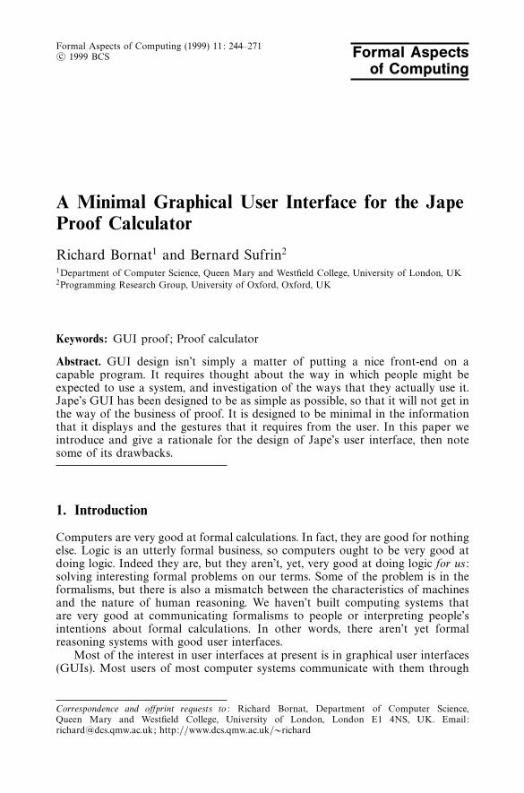
Since box-and-line proofs are read line by line, from top to bottom, it seemsnatural to many of our users to try to construct them in that order. The proofof Fig. 3, as a tree, was constructed backwards, from conclusion to hypotheses.Contrast Figs 5a and 5b, which show early steps in a proof of the same conjecture,but work forward from the hypotheses. The first step is to use ∧-E to extractQ∨R from the premise, the second to use ∨-E to extract Q and R, the third ∧-Eagain to extract P from the premise. These steps of forward reasoning seem morenatural to us (and, it seems, to our users) than the planning that must go on toproduce Fig. 3. The comparison is unfair, of course – nobody would seriously tryto use a logic like Fig. 1, which only manipulates right-side formulae, to producea proof like Fig. 3, which must deal with left-side formulae as well (for example,P ∧ (Q ∨ R) in the first step of Fig. 3). But that is to say no more than that insome logics forward reasoning from tip to root makes best sense.
Jape supports the kind of forward reasoning illustrated here by making heavyuse of cut steps in the internal representation of the proof, and then applying
254 R. Bornat and B. Sufrin
(a)
(b)
Fig. 5a. A first forward step. b. After the third forward step.
Fig. 6. The tree after the first forward step.
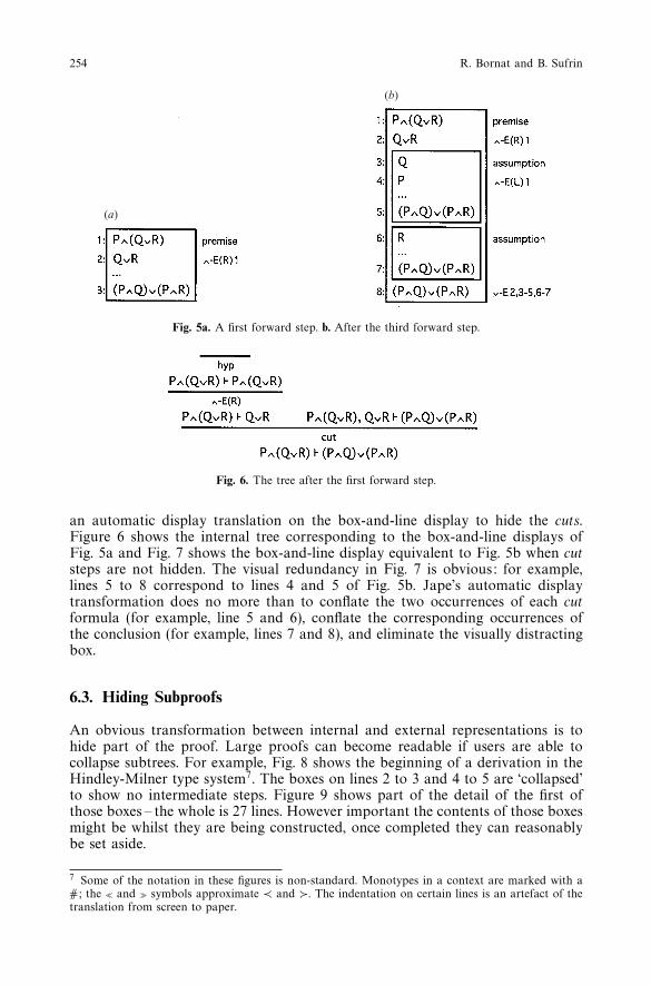
an automatic display translation on the box-and-line display to hide the cuts.Figure 6 shows the internal tree corresponding to the box-and-line displays ofFig. 5a and Fig. 7 shows the box-and-line display equivalent to Fig. 5b when cutsteps are not hidden. The visual redundancy in Fig. 7 is obvious: for example,lines 5 to 8 correspond to lines 4 and 5 of Fig. 5b. Jape’s automatic displaytransformation does no more than to conflate the two occurrences of each cutformula (for example, line 5 and 6), conflate the corresponding occurrences ofthe conclusion (for example, lines 7 and 8), and eliminate the visually distractingbox.
6.3. Hiding Subproofs
An obvious transformation between internal and external representations is tohide part of the proof. Large proofs can become readable if users are able tocollapse subtrees. For example, Fig. 8 shows the beginning of a derivation in theHindley-Milner type system7. The boxes on lines 2 to 3 and 4 to 5 are ‘collapsed’to show no intermediate steps. Figure 9 shows part of the detail of the first ofthose boxes – the whole is 27 lines. However important the contents of those boxesmight be whilst they are being constructed, once completed they can reasonablybe set aside.
7 Some of the notation in these figures is non-standard. Monotypes in a context are marked with a#; the - and . symbols approximate ≺ and 0. The indentation on certain lines is an artefact of thetranslation from screen to paper.

A Minimal Graphical User Interface for the Jape Proof Calculator 255
Fig. 7. Box-and-line display with visible cuts.
Fig. 8. A partial proof in the Hindley-Milner type inference algorithm, with completed subtrees (boxes2-3, 4-5) collapsed.
Fig. 9. Part of the first internal box from Fig. 8.

256 R. Bornat and B. Sufrin
Fig. 10. A partial proof in the Hindley-Milner type inference algorithm, with generalisation stepsummarised.
Fig. 11. A rewrite rule.
Fig. 12. Rewrite equations.
The same transformation can be applied automatically, at the choice of thelogic encoder, to particular subtrees. This is especially useful when a subtree isan automatic derivation. Continuing with the same example, Fig. 10 shows thedisplay after generalisation steps have constructed type schemes and instantiatedthe unknowns of Fig. 8. There is a behind-the-scenes structural induction, pro-grammed in Jape’s tactic language, which produces the conclusions on lines 6 and7. The activity is intricate enough whilst the result is being constructed, substitut-ing type variables for unknowns, but once constructed it is simply impenetrable.It’s preserved in the internal proof for the sake of soundness (and for replayingthe proof if necessary), but far better to hide it from the user’s eyes.
A more inventive use of hiding is employed in a treatment of equationalreasoning in functional programs, where some antecedents of certain steps areentirely omitted. Using the rule of Fig. 11 and the equational definitions ofFig. 128, Fig. 13a shows the beginning of a proof in this particular logic.
Figure 13b shows the same proof, with the left antecedent of each rewrite stepentirely omitted, and the justification of the step appealing to the equation used
8 In this particular treatment the encoder has decided to base definitions on associative concatenation(++) rather than consing (:). Although function definitions then require particular care, some proofsare easier to construct and to read. It is a design aim that Jape should support the logic encoder’schoice, as in this case, and not require notations to fit some prejudged convention.

A Minimal Graphical User Interface for the Jape Proof Calculator 257
(a)
(b)
Fig. 13. (a) A partial proof in functional programming. (b) The same proof, with hidden antecedents.
Fig. 14. (a) A partial proof in transitive style. (b) The same proof with transitivity steps exposed.
to close the left antecedent, following [BiW91]. Following [DaB73] ‘fold’ meansright-to-left rewriting, and ‘unfold’ left-to-right.
By hiding certain subtrees Jape is able to show a proof at an appropriate levelof abstraction. To the user, functional programming definitions have the status ofrules, and substitutivity of equals is taken for granted. In the engine, substitutivityis a necessary step in using the rules. Hiding substitutivity steps, and labellingthe proof as if just the definitions had been used, brings the display closer to theuser’s mental model. Decisions about where to do this are under the control ofthe logic designer.
6.4. Pseudo-transitive Reasoning
Lines 1 to 3 of Fig. 13b are the first steps in a proof by equational transformationthat (rev • rev)x = id x. Reading backwards, as the proof was constructed, at first(rev • rev)x is transformed into rev(rev x) by unfolding the definition of (•); thenid x is transformed into x, again by unfolding. But because the proof is constructedbackward and read forward, the justifications must both appeal to folding. Thereis a discrepancy between what the user commanded and what the tool displaysthat has to be explained – that means extra cognitive effort on the user’s partto understand and then discount the discrepancy, and an over-complicated user’smental model.
There is a much more natural way of writing that sort of proof down,appealing implicitly to transitivity of equality, illustrated in Fig. 14a. An advantageis that the direction of rewriting, somewhat obscure in Fig. 13b, can be seendirectly in the display. In this kind of display the left-to-right steps (for exampleline 1 to line 2) are correctly described as unfoldings. The right-to-left steps (forexample line 4 to line 3) are visibly different, are constructed backwards, andtherefore it isn’t surprising that they are differently justified.
Figure 14b shows the proof with transitivity steps exposed (but with sub-
258 R. Bornat and B. Sufrin
stitutivity hidden, as before). The transitivity-hiding transformation which givesFig. 14a is similar to the cut and identity-hiding transformation illustrated dis-cussed above, exploiting the analogy on the one hand between identity rules (e.g.hyp, axiom) and the reflexivity axiom A = A of equational reasoning, and on theother between cut and the transitivity of equality. Reflexivity moves a formulafrom left to right of an equation, just as an identity rule moves a formula fromleft to right of the sequent. Transitivity introduces an intermediate formula tobe worked on, moving it from the right side of one equation to the left sideof the other, just as cut moves an intermediate formula from one side of thesequent to another. Even though Fig. 14a uses one more line than Fig. 13b, itsclearer treatment of the fold/unfold nomenclature and the lack of repetition ofintermediate results makes it far easier to read and to understand.
7. Gestures
Given a convenient display of a proof or a proof-in-progress, it is necessary toallow the user to gesture at it. Within the current GUI vernacular and at thecurrent stage of hardware development, the gestures are made with a mouse. Itis nearly always possible to design the interaction with a logic so that Jape canbe operated without using a keyboard, except when adding new conjectures to apanel.
Gestures at Jape’s display are interpreted by interaction tactics written in itsprogramming notation by a logic encoder. Those tactics aren’t described here, buttheir main function is to take note of the gesture context in which a commandis issued and interpret the user’s gestures according to the wishes of the encoder.Since Jape’s internal representation is an inference tree but the display can be asummary of the tree or a version of box and line, the main technical difficulty inimplementing on-screen gestures has been in relating gestures made at the displayto the corresponding positions in the internal tree.
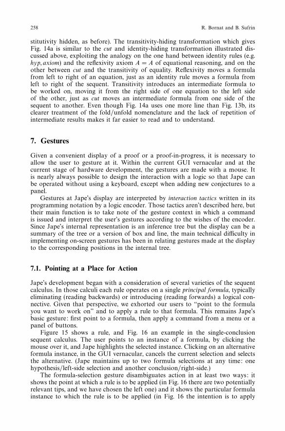
7.1. Pointing at a Place for Action
Jape’s development began with a consideration of several varieties of the sequentcalculus. In those calculi each rule operates on a single principal formula, typicallyeliminating (reading backwards) or introducing (reading forwards) a logical con-nective. Given that perspective, we exhorted our users to “point to the formulayou want to work on” and to apply a rule to that formula. This remains Jape’sbasic gesture: first point to a formula, then apply a command from a menu or apanel of buttons.
Figure 15 shows a rule, and Fig. 16 an example in the single-conclusionsequent calculus. The user points to an instance of a formula, by clicking themouse over it, and Jape highlights the selected instance. Clicking on an alternativeformula instance, in the GUI vernacular, cancels the current selection and selectsthe alternative. (Jape maintains up to two formula selections at any time: onehypothesis/left-side selection and another conclusion/right-side.)
The formula-selection gesture disambiguates action in at least two ways: itshows the point at which a rule is to be applied (in Fig. 16 there are two potentiallyrelevant tips, and we have chosen the left one) and it shows the particular formulainstance to which the rule is to be applied (in Fig. 16 the intention is to apply

A Minimal Graphical User Interface for the Jape Proof Calculator 259
Fig. 15. The ∀ # rule of the single-conclusion sequent calculus.
Fig. 16. Pointing to a principal formula within a sequent at a particular point in the tree.
∀ #, and there are two formulae in the left tip which could match the formulae∀x.A(x) in the rule).
A user who attempts to apply the ∀ # rule to the proof of Fig. 16b withoutmaking any formula selection at all is told, by the interaction tactic invoked fromthe menu entry labelled ∀ #, to select a sequent to work on. If the user selectsthe conclusion formula in the left tip then only half the disambiguation job – theselection of left or right tip – has been done. If the ∀ # rule is then applied, thereis a choice of principal formulae. The dialogue box with which Jape asks the userto disambiguate that choice is a distraction at best, and confusing at worst9. Weencourage our users to think of its appearance as an indication of a mistake andwe reinforce the intended mental model by telling them to point to the formulathey want to work on.
In the tree presentation of a sequent calculus the exhortation “point to theformula you want to work on”, coupled with a menu of formula-simplificationcommands, makes an understandable and memorable user’s mental model. Thesame slogan makes perfect sense when working backwards in a natural deductionlogic in the box-and-line display since, even when part of the proof is hidden,there always is a straightforward mapping from conclusion lines in the display tonodes of the tree.
We would be less than honest if we pretended that this was the whole truth.There are problems with gestures directed at the box-and-line display. Eventhough natural deduction, in this presentation, is one of Jape’s most popularand successful logic encodings, it introduces gesturing problems that our usersencounter and protest about, and we discuss some of these below.
7.1.1. Forward Reasoning with Multi-antecedent Elimination Rules
Our exhortation needs reinforcing when making forward steps with naturaldeduction rules which have more than one antecedent. For example, given therule of Fig. 17, and the problem of figure 18, novice users at first expect to haveto point to lines 2 and line 4 before applying the rule, but Jape’s mechanism onlyallows them to point to a single antecedent formula. Our exhortation “point to theformula you want to work on” appears in this case to explain Jape’s behaviour,
9 We aren’t proud of the low quality of Jape’s error messages. We advise our users to read them as“Whoops! You shouldn’t do that!” if they don’t understand them. Our principles have temporarilygiven way to our lack of resources.

260 R. Bornat and B. Sufrin
Fig. 17. The →-E rule of natural deduction.
Fig. 18. Just before a → -E step.
and seems to change their notion of the task by focusing attention on the logicalconnective in the formula – after all, it is an elimination rule that is being applied.The change is productive, in that they are better at finding proofs once they obeyit, but we would prefer to support the more obvious gesture, using the slogan tosell a more efficient proof search strategy to experts.
7.1.2. Forward Reasoning with Introduction Rules
Jape doesn’t effectively support forward reasoning with multiple-antecedent rulesin which no antecedent has an operator to focus upon. The rule of Fig. 19 andthe partial proof of Fig. 20 demonstrate the difficulty. Our novice users wouldprefer to make the next step by pointing to lines 2 and 4 and invoking the ∧-I rule.Instead they must work backwards from line 5, first with ∨-I(L) and then with∧-I . The proof can be made, and without gestural complication, but it doesn’tfollow the user’s mental model.
Although Jape doesn’t at present support multiple formula selection, itwouldn’t be difficult to make it do so. Then it would be possible to allowour users, given the problem of Fig. 20, to select first P on line 2, second Q online 4, and then apply the rule of Fig. 19, taking the order of selection as animplicit description of the result intended – P ∧ Q in this case. Selection in theother order would produce Q ∧ P : it would be as easy to undo that mistake asany other, and trivial to make the right gestures the second time round.
But we have so far refused to satisfy our user’s demands by implementingsuch a gesture. Nothing in Jape’s mechanism stands in our way: the techniqueof cut hiding would serve as well to construct this forward step as any other.
Fig. 19. The ∧-I rule of natural deduction.

A Minimal Graphical User Interface for the Jape Proof Calculator 261
Fig. 20. A point at which forward reasoning with the ∧-l rule isn’t supported by Jape.
Fig. 21. A Family of rules.
Our reluctance is to do with the GUI and the visual representation of the user’sgestures. Although Jape can’t do so at present, we have in mind that it will oneday support families of rules like the one in Fig. 21. Suppose that you wantedto use this rule to combine five antecedents: you can’t see the order in whicha large number of selections were made by looking at undifferentiated markson the screen, yet if we supported multiple-antecedent selection, then the orderwould be important. It’s quite hard to make five selections in the right orderwithout visual feedback, and it’s hard to see how that feedback could be giveneffectively. Worse still, it’s difficult to see how a mistaken order of selection couldbe corrected without cancelling and starting again.
We haven’t yet thought of a minimalist interaction which solves this problemso it remains an obstacle to our users’ smooth progress with natural deductionproofs. We don’t believe that we have been too fussy, or that the best is the enemyof the good in this case. The need to deal with families of rules in the foreseeablefuture seems to rule out the easy ad-hoc solution.
7.1.3. Ambiguity of Hypothesis Selections
The economy of the box-and-line display lies in the fact that it displays left-sideformulae only once. But this means that pointing to a left-side formula may not

262 R. Bornat and B. Sufrin
Fig. 22. A tree with two open tips.
(a) (b)
Fig. 23a. Selection of hypothesis formula doesn’t indicate unique tip of tree of Fig. 22. b. Hypothesisselection disambiguated with conclusion selection.
uniquely identify a tip of the tree and thence a point at which to apply a rule. Inthe tree of Fig. 22 the hypothesis P ∧ (Q ∨ R) occurs in every sequent and thereare two open tips. Pointing to an occurrence of P∧ (Q∨R) in either tip of the treeindicates the point at which to apply a rule. In the corresponding box-and-linedisplay of Fig. 23a that formula only occurs once on line 1, and selecting it10
doesn’t indicate whether it is the tip which corresponds to lines 3–4 or that whichcorresponds to lines 5–6 which is to be worked on11.
In Jape’s box-and-line display forward expansion of the proof must be aboveone of the growing points indicated by “· · ·”, just as backwards expansion mustbe below such a point, and there is one such growing point for each tip in thetree. To indicate a tip when more than one is available, we require the user topoint to a conclusion formula in order to indicate the rule-application positionin the tree. This is unnatural when working forward, because the user’s mentalmodel doesn’t encompass the conclusion: a forward step just goes forward. It isJape’s mechanism that should give way, but for the moment we have not beenable to make it do so. Our best effort is to try to alter the user’s perception of thetask with the slogan “point to the conclusion you want to work towards”. Theslogan is moderately effective because it is reinforced by the error report whichJape produces given the single selection of Fig. 23a, but we are aware that itdoesn’t solve the problem.
10 Selection draws a box close round a formula, just as it does in the tree display. There doesn’tappear to be any confusion in the minds of our users between the small selection box and the muchlarger boxes which enclose hypothetical proofs in box-and-line display.11 Line 7 of Fig. 23a is ‘greyed out’ because it isn’t relevant to the hypothesis on line 1: it correspondsto a proved conclusion in the tree of Fig. 22. In figure 23b lines 5 and 6 are greyed out as well,because they correspond to the right-hand open tip of Fig. 22 and aren’t relevant to the conclusionon line 4, which comes from the left-hand open tip. In general Jape greys out lines whose formulaecan’t be used as part of a proof step which works on selected formulae.

A Minimal Graphical User Interface for the Jape Proof Calculator 263
7.1.4. Cut Splicing
Given the single selection shown in Fig. 23a, and the application of the ∧-E(L)rule, there is an obvious place to make the proof grow: just below line 1, givingFig. 20. That would have the advantage, in a box-and-line proof, that the formulaP which is extracted could be used as a hypothesis throughout the rest of theproof. The display and the gesture together suggest strongly that Jape ought tobe more capable than it is. It’s not unusual for a user’s mental model to partcompany with a GUI’s behaviour for that reason.
We have envisaged a mechanism which would solve this problem in Jape,but implementation is a daunting prospect – in principle it involves splicing anew cut step above the node which introduces the selected hypothesis (the rootof the tree, in the case of Fig. 23a) and repeating all the steps above that pointwith a new collection of left-hand-side formulae. We don’t know any other prooftools which attempt this kind of transformation, but it seems natural, it would beuseful, and we therefore can find no excuse not to implement it eventually. Thisis an example of the way that a GUI presentation forces the internal mechanismsto fall into line with the user’s mental model: the display, the gesture and themental model together have made natural and inevitable a development whichmight otherwise seem baroque.
A further development of the same mechanism might also solve difficultiesassociated with the fact that the sequence of lines is derived simplistically fromthe internal tree. In a box-and-line proof it should always be possible to useline j as an antecedent in a proof of line k when j precedes k and the scopingof hypotheses (indicated by the box structure) doesn’t prohibit it. A possiblemechanism would introduce every conclusion formula as a hypothesis by usinga cut, and close all non-cut antecedents with an identity rule. Implementation isas yet a speculative possibility, fraught with interesting technical problems. If wecan pull it off it will be yet another example of the way in which the requirementsof the user’s mental model can usefully drive the development of the GUI’sunderpinning in the proof engine.
7.2. Providing an Argument to a Command
Jape uses unification at every step, and it is prepared to defer almost all of itsunification decisions, if necessary, until enough information is available to resolvethem. The purpose is to allow proof search to be underdetermined, to allow theuser to make choices about the identity of problematic proof components asthe proof develops and at an appropriate stage of the proof. In particular thisallows use of Jape as a true calculator (for example, in the Hindley-Milner typeinference system illustrated in Figs 8, 9 and 10), but it is useful in more mundanecircumstances as well. Figures 24a and 24b show an example of backwards proofsearch in an encoding of natural deduction where the negation rule involves anexplicit contradiction. The unknown B in Fig. 24b is a place-holder, a sign thatsomething isn’t decided. Resolution of the uncertainty in the step from Fig. 24bto 24c clarifies the situation and calms the display considerably.
Useful as it can be during search, the introduction of an unknown can oftenbe a confusing distraction into a proof which is essentially a verification. Anyrule which doesn’t have the subformula property can illustrate the problem. Forexample, Fig. 25 shows a version of the ∃-intro rule which employs a version of

264 R. Bornat and B. Sufrin
(a)
(b)
(c)
Fig. 24.
Fig. 25. A rule which doen’t have the subformula property.
variable scoping and Fig. 26 the corresponding scoping rule. Figure 27a showsa position at which the ∃-intro rule can be applied and Fig. 27b the effect of anapplication of the rule.
Unknowns are an essential mechanism when there is a real search for a gen-uinely unknown formula; otherwise they are visually and cognitively distracting.Here we’ve chosen to emphasise the potential distraction by illustrating use of arule which includes a normally-hidden antecedent, a side condition that a par-ticular variable name must be in scope at the point of application of the rule.In this case the unknown is a meta-logical device, an intrusion of an encodingmechanism into the world of proof.
In applying a rule like that of Fig. 25, then, our users may want to providean argument formula to help define the particular rule instance that will be used.We prefer to avoid use of the keyboard, and the only alternative is to select fromthe text available in the proof. But this selection isn’t indicating a position inthe proof nor a formula to be worked on, so it’s necessary to use a differentgesture. The text-selection vernacular in word processing is press-and-drag, a‘wipe’ movement across text to be chosen, and we have used exactly the samegesture. Text selection is highlighted distinctively, as illustrated by the shading online 3 of Fig. 28a.
That text selection, followed by application of the rule from Fig. 25, producesFig. 28b (here the logic encoder has chosen to apply the rule of Fig. 26 automat-ically as part of the proof step, and to hide the line generated by that substep).This is a far quieter display than Fig. 27b – though when the unknown and the
Fig. 26. The scoping rule.

A Minimal Graphical User Interface for the Jape Proof Calculator 265
(a)
(b)
Fig. 27a. Before application of the ∃-l rule. b. After injudicious application of rule.
(a)(b)
Fig. 28. Sub-formula selection provides argument. b. After application of rule with argument.
strange antecedent do appear there is something to be learnt from their jarringintrusion into a quiet proof.
In Jape the gesture context – roughly, what has been selected and where - isthe raw material on which interaction tactics feed. If we wish it we can avoidentirely the particular problem illustrated in Fig. 27b, by designing our menusand buttons to invoke a tactic which complains if there isn’t a text selectionsuitable to be an argument to the rule application, or applies the rule silently ifthere is such a selection. This is an example of the way that a logic encoder canmake proof quieter than Jape’s normal operation would make it, hiding detailsof the logic from its users.
It is normal in formula-manipulation tools to provide some kind of structuralsubformula selection, rather than the simple text selection provided here. We areconcerned to be able to deal with formulae like x + y + z, where y + z is avisual but not a structural subformula, given a normal left-to-right parse of theformula (the structural problem would be exacerbated if + were to be treated

266 R. Bornat and B. Sufrin
Fig. 29. A rule which is best applied to a user-defined substitution.
(a)
(b)
Fig. 30.
as an associative operator). The whole issue of simple manipulation of operatorswhich may be treated syntactically or semantically as associative is one that weare acutely aware of. We’d be reluctant, because it would hardly be minimalist,to have two similar gestures, one for textual selection and the other for structuralselection.
7.3. User-defined Substitutions
It isn’t necessary for Jape to interpret a text selection as a rule argument. In thecase of a rule which uses a substitution form, for example that in Fig. 29, wewould expect Jape to interpret a text selection as defining a site for rewriting.
Rules like that in Fig. 29 have to match an explicit substitution formula to aproblem formula. That requires higher-order unification, and to begin with Japeused a version of that algorithm, with aid from the user to indicate the substitutedformula X. But that gave too little control to the user, was difficult to understandand so wasn’t quiet or minimalist enough.
The mechanism now used by the proof engine in Jape, under the logicencoder’s direction, is to interpret a text selection, or a number of simultaneoustext selections in a single proof formula, as a description of a substitutionform. A user-defined substitution needs special treatment because it’s fragile –that is, it’s guaranteed to collapse immediately, by normal substitution-reductionmechanisms, back into the formula from which it was made. Jape’s usual treatmentof substitution forms is to simplify them out of existence whenever possible,so user-defined substitutions are specially marked as fragile, and Jape treatsthem gently during unification. Figure 30a shows an example of the preparationfor a use of the rule in Fig. 29: we want to perform induction on both theoccurrences of x, and the text selections implicitly describe the substitution form(rev(rev v) = v){v\x}. Figure 30b shows the effect of the application of the rule.
Naturally we don’t tell our users that they are constructing substitutions inorder to represent selected subterms. We explain the gesture with the slogan

A Minimal Graphical User Interface for the Jape Proof Calculator 267
Fig. 31. The list induction rule without explicit substitution forms.
Fig. 32. A rewrite rule which uses substitution forms.
“select the subformula(e) you want to work on”, and to date it has fitted wellinto every one of the logics we have encoded.
Logic encoders need not even write the rule in terms of substitution but mayuse the kind of ‘abstraction’ or ‘predicate’ notation familiar from the mathematicalvernacular. Figure 31 shows how induction would be described in the encodingof the logic.
User-constructed substitutions indicate positions in formulae in the same waythat formula selections indicate positions in the tree. We have only just begunto explore their potential and we anticipate that we will be able to use them toimplement a version of proof by pointing [BkT95].
7.4. Interpretation of Substitution Forms
The technique of user-directed substitution makes it easy to use Jape as a rewriteengine, and extended use has exposed a technical problem. It begins not as aGUI problem but a meta-logical difficulty with the interpretation of substitutionforms. For example, in a classical logic the equivalence of P → Q and ¬P ∨ Q isprovable, and many users would expect to be able to use that equivalence with arewrite rule like that of Fig. 32.
That works well in most circumstances, but there’s a problem when attemptingto rewrite at a position within a binding construct. For example, (∀y(v)){v\(A(y) →B(y))} doesn’t reduce to ∀y(A(y) → B(y)), and that means we can’t replaceA(y) → B(y) with ¬A(y) ∨ B(y) in that context using the rule of Fig. 32.
The problem is that formal substitution, as it’s normally understood, doesn’tsupport the notion of substitutivity of equals sufficiently well. We can see, meta-logically, that if P → Q is equivalent to ¬P ∨ Q in any context or none, then itwould be safe to rewrite with that equivalence at any subformula position. Thatcan be expressed [Gri98] by employing a notion of ‘uniform substitution’. If weinterpret A{v\\E} to mean “replace every unbound occurrence of v in A by E anddon’t worry about variable capture”, then a rule like Fig. 33 will be admissible inmost logics, and the example problem will be solved.
This doesn’t quite solve Jape’s problem, though, because not every rewritecan be based on so absolute an equivalence. Because a proof tool has to adhereprecisely to the principles of substitution simplification and follow the rules of a
Fig. 33. Rewriting with uniform substitution forms.

268 R. Bornat and B. Sufrin
Fig. 34. A multiplicative rule.
Fig. 35. A deferred context split, and use of drag-and-drop to resolve the ambiguity.
logic absolutely literally, it will frequently come across situations where a rewriteis not always as straightforward as a user might hope. Then it will be necessaryto choose between two equally unpleasant alternatives: either it must deny thedesired step without explanation, or it must explain more about the workingsof substitution forms than the average user will wish to know. Our intention toproduce a tool with minimal interaction and passive adherence to a user’s wishesseems to have hit a brick wall at this point.
7.5. Drag and Drop
Many logics use context-splitting rules to illustrate how hypothesis formulaecan be treated as resources during the proof of antecedents. This is taken mostseriously in linear logic [Gxx89] where multiplicative rules split both left and rightcontexts - see, for example, Fig. 34.
Jape supports this kind of rule, and when one is applied it defers a decisionabout the division of formulae between left and right subtrees. The internalmechanism uses a proviso which says that the proof is acceptable provided thatsome way is found to resolve the context split – that is, so that a specified collectionof formula instances unifies with a specified collection of context variables.
Using Jape’s normal proof mechanisms it’s possible to complete many proofsusing identity rules (axiom, hyp) to demand unifications which implicitly resolvethe context-splitting ambiguity. But it’s difficult to make proofs in that way,
A Minimal Graphical User Interface for the Jape Proof Calculator 269
Fig. 36. A rule which uses explicit thinning.
Fig. 37. Explicit thinning involves context variables not shown in the proof.
because until it is completed the proof will contain a lot of unknowns, and a useris required to devise and carry out an intricate unification and search strategyto eliminate them. Better to use gestures to resolve the ambiguity if we can, andJape employs drag-and-drop for the purpose.
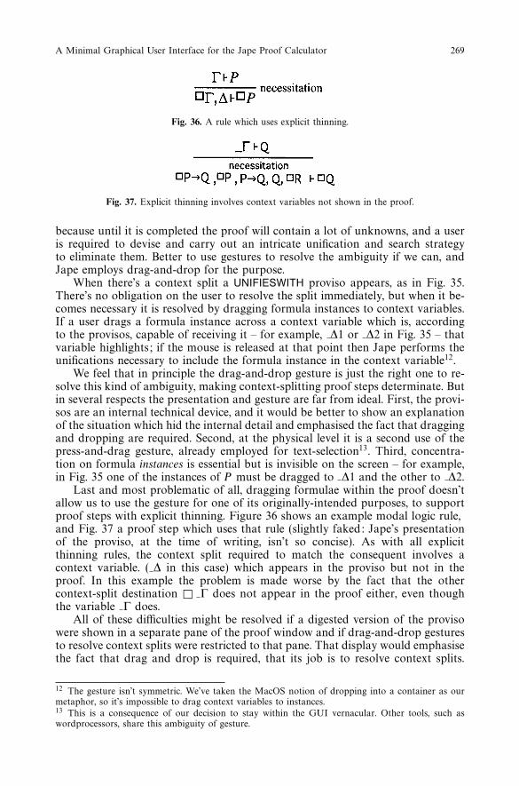
When there’s a context split a UNIFIESWITH proviso appears, as in Fig. 35.There’s no obligation on the user to resolve the split immediately, but when it be-comes necessary it is resolved by dragging formula instances to context variables.If a user drags a formula instance across a context variable which is, accordingto the provisos, capable of receiving it – for example, ∆1 or ∆2 in Fig. 35 – thatvariable highlights; if the mouse is released at that point then Jape performs theunifications necessary to include the formula instance in the context variable12.
We feel that in principle the drag-and-drop gesture is just the right one to re-solve this kind of ambiguity, making context-splitting proof steps determinate. Butin several respects the presentation and gesture are far from ideal. First, the provi-sos are an internal technical device, and it would be better to show an explanationof the situation which hid the internal detail and emphasised the fact that draggingand dropping are required. Second, at the physical level it is a second use of thepress-and-drag gesture, already employed for text-selection13. Third, concentra-tion on formula instances is essential but is invisible on the screen – for example,in Fig. 35 one of the instances of P must be dragged to ∆1 and the other to ∆2.
Last and most problematic of all, dragging formulae within the proof doesn’tallow us to use the gesture for one of its originally-intended purposes, to supportproof steps with explicit thinning. Figure 36 shows an example modal logic rule,and Fig. 37 a proof step which uses that rule (slightly faked: Jape’s presentationof the proviso, at the time of writing, isn’t so concise). As with all explicitthinning rules, the context split required to match the consequent involves acontext variable. ( ∆ in this case) which appears in the proviso but not in theproof. In this example the problem is made worse by the fact that the othercontext-split destination ! Γ does not appear in the proof either, even thoughthe variable Γ does.
All of these difficulties might be resolved if a digested version of the provisowere shown in a separate pane of the proof window and if drag-and-drop gesturesto resolve context splits were restricted to that pane. That display would emphasisethe fact that drag and drop is required, that its job is to resolve context splits.
12 The gesture isn’t symmetric. We’ve taken the MacOS notion of dropping into a container as ourmetaphor, so it’s impossible to drag context variables to instances.13 This is a consequence of our decision to stay within the GUI vernacular. Other tools, such aswordprocessors, share this ambiguity of gesture.

270 R. Bornat and B. Sufrin
In particular it would resolve the physical ambiguity: press-and-drag could meanone thing in the proof pane, another in the context-split pane. We’re not entirelyconvinced that this would be the best solution, though: it feels like a bit of spacecadet machinery, and we’d prefer to do everything on the simple display of theproof. Experiment is required, but the example of Fig. 37 will probably decidethe issue, since without a special display mechanism it’s hard to see how a usercould resolve that kind of split at all.
8. Related Work
Our original inspiration in devising Jape came from [Dcy87, Daw90, JJL91]. TheTarski’s world program [BaE93] is a more recent influence. The CMU proof tutor[ScS93] is an educational tool which has a graphical user influence but is by nomeans so quiet as Jape.
Our attempts to design and implement passive tools goes back to the late1970s [BoT89]. Our interest in educational uses of formal calculators originatedin the Calculator project at QMW [FuO96].
Most of the work in user interfaces for proof tools considers the problem ofattaching a user interface to a powerful pre-existing theorem prover, an approachwhich we have explicitly rejected. The work associated with the Coq theoremprover has been a rich source of competitive challenges for us, especially [TBK92]and [BkT95].
9. Conclusions
GUI design, taken seriously, is a subtle business. A minimalist GUI for a usefulproof tool looks, after six years experimental development of Jape, more and morepossible. There is still much work to do, concentrating on the fine details of thedisplay and the interpretation of gestures, and each advance in the capabilities ofthe tool will introduce new problems. The most obvious challenge to minimalismis to support derivations in logics (such as program derivation logics, and calculiof refinement) in which formulae can become huge (because they are programs);we are beginning work on such problems. (Jape can already deal with the logicalcontent of such calculi: the problem is in the display and navigation of longderivations involving very large formulae, where another layer of display abstrac-tion seems to be necessary, and another layer of gesturing seems unavoidable.)
So far as the display is concerned, our principle has been to make it as quietas possible: that is, to look as much as possible like the proof that might be in auser’s head, and to describe as little as possible of the internal workings of thetool. Quietness isn’t a design method, however, it’s a design principle: since wecan’t make our tools actively helpful, then let us make them passively and quietlyresponsive, and see if that will do.
Quietness is largely achieved by hiding details and mechanism, thus makingthe tool seem much simpler than it really is, but quietness is not simply a ‘lessis more’ slogan. We have quietened our interface by leaving a great deal out, tobe sure: for example, by restricting the kinds of gesture which we are preparedto recognise. But when the display shows what the user expects to see – as, forexample, in the case of transitive proof – then it is quieter as a result, because itdoes not require a mental translation from what is displayed to what is intended.

A Minimal Graphical User Interface for the Jape Proof Calculator 271
In this case the tool has become quieter by becoming more capable, though itsimplementation has become more complex.
Gesture interpretation is the most active area of development. It’s necessaryto resolve the ambiguity inherent in rule application with a variety of gesturesrich enough to convey those intentions concisely, but which still use no more thanthe parsimonious vernacular of point-and-click, press-and-drag which is all thatusers, operating systems and programming-language libraries can deal with atpresent. Jape’s formula-selection, substitution-selection, subformula-selection andcontext-variable-dragging are a first step towards the goal of a user interface thatcan truly communicate with a theorem prover.
References
Jape web sites: http://www.dcs.qmw.ac.uk/∼richard/jape andhttp://www.comlab.ox.ac.uk/oucl/users/bernard.sufrin/jape.html
[App90] Apple Computer Inc.: Macintosh Human Interface Guidelines, Addison-Wesley, 1990.[BaE93] Barwise, J. and Etchemendy, J.: The language of first-order logic, CSLI, 1993.[BkT95] Bertot, Y., Kahn, G. and Thery, L.: Proof by Pointing. LNCS 789, 141–160, 1995.[BiW91] Bird, R. S. and Wadler, P.: An Introduction to Functional Programming Prentice-Hall
International, 1991.[BoT89] Bornat, R. and Thimbleby, H.: “The life and times of ded, text display editor”, in
Cognitive Ergonomics and Human-Computer Interaction, Long and Whitefield (eds) CUP,1989.
[DaB73] Darlington, J. and Burstall, R. M.: “A System which Automatically Improves Programs”,Proceedings of the 3rd IJCAI, Stanford, 1973.
[Daw90] Dawson, W. M. G.: A Generic Logic Environment, PhD thesis, Imperial College,University of London, 1990.
[Dcy87] Dyckhoff, R.: Implementing a simple proof assistant, in Workshop on Programming forLogic Teaching, Leeds, July 1987 (program available from Machine Assisted LogicTeaching Project, Computational Science Division, University of St Andrews), 1987.
[Fit52] Fitch, F. B.: Symbolic Logic, Ronald Press, New York, 1952.[FuO96] Fung, P. and O’Shea, T. M. M.: “Computer tools to teach Formal Reasoning”, Computers
and Education, 27(1), 1996.[Gxx89] Girard, J.-Y. et al.: Proofs and Types. Cambridge Tracts in Theoretical Computer Science
7, Cambridge University Press, 1989.[Gri98] Gries, D.: “Uniform substitution” (private communication), 1998.[JJL91] Jones, C. B., Jones, K. D., Lindsay, P. A., Moore, R.: mural: A Formal Development
Support System. Springer-Verlag, 1991.[MeH96] Merriam, N. A. and Harrison, M. D.: Evaluation and Comparison of Three Theorem
Proving Assistants, Eurographics Workshop on Design, Specification and Verification ofInteractive Systems, Springer-Verlag, 1996.
[Nor98] Norman, Donald A.: The Invisible Computer: Why Good Products Can Fail, the PersonalComputer Is So Complex, and Information Appliances Are the Solution, MIT Press, 1998.
[NeL95] Newman, William and Lamming, Mik: Interactive System Design Addison-Wesley, 1995.[NeS79] Newman, William and Sproull, R. F.: Principles of Computer Graphics, McGraw-Hill,
1979.[ReC93] Reeves, S. and Clarke, M.: Logic for Computer Science. Addison-Wesley, 1990.[ScS93] Scheines, R. and Sieg, W.: The Carnegie Mellon Proof Tutor. In Judith V. Boettcher
(Ed.), 101 Success Stories of Information Technology in Higher Education: The Joe WyattChallenge. McGraw-Hill, 1993.
[TBK92] Thery, L., Bertot, Y. and Kahn, G.: Real Theorem Provers Deserve Real User-Interfaces.Fifth ACM Symposium on Software Development Environments, 1992.
[Thi90] Thimbleby, Harold: User Interface Design, ACM Press, 1990.[WoD96] Woodcock, J. and Davies, J.: Using Z: Specification, Refinement and Proof. Prentice-Hall
International, 1996.
Received November 1998
Accepted in revised form June 1999