Embed Size (px)
Citation preview

FRP JACKETED STEEL
UNDERGROUND STORAGE TANKS
INSTALLATION INSTRUCTIONSR923-07
1.0 EXCAVATION AND BEDDING1.1 The bottom of the excavation shall be covered
with a minimum of 12 inches (305 mm) ofbedding, suitably graded and leveled. Beddingand backfill material surrounding the tank, to awidth and depth of 12 inches (305 mm) all aroundthe tank, shall be clean material.
1.2 Where anchoring by means of a concrete pad, thetank shall not be placed directly on the pad. Bedding material at least 6 inches (152.4 mm)deep must be spread evenly over the dimensionsof the pad to separate the tank from the pad.
1.3 Bedding and backfill material shall consist of homogenous pea gravel, crushed stone, cleansand or natural earthen materials. Crushed stone,clean sand and natural earthen materials shall becapable of passing 100% through a 1/2 inch (13mm) sieve and no more than 12% by dry weightthrough a #200 sieve (0.0029 inch (0.0754 mm)). Pea gravel shall be no larger than 3/4-inch (19mm). The materials shall be free of all foreignmaterials, such as but not limited to, bricks,metals, concrete and plastics.
1.4 The backfill material may be from the tank site if it meets this description, or it may be delivered to the site from another source.
1.5 Sand or natural earthen materials used as backfillshall be placed into the excavation in 12-18 inch(305-458 mm) vertical lifts, compacted after eachlift, at least 60% up the vertical height of the tank.
1.6 If earthen material from the site, or other earthenmaterial, is to be used as bedding or backfillmaterial, a minimum of four 1 cu.ft. samples shallbe taken from different locations which arerepresentative of the backfill material and the site.
1.7 In a tidal area, the tank "bedding" material shall becrushed stone or pea gravel. Sand and naturalearthen material may be used only if measures aretaken to prevent washout of material during thedesign life of the system.
2.0 INTERSTICE VACUUM MONITORING2.1 Assure tightness of tank and secondary containment
in accordance with NFPA 30 through verification ofvacuum within tank interstice (space in between thesteel storage tank and outer fiberglass reinforcedplastic (FRP) shell).
2.2 The tank is shipped from the factory with aminimum 13 inches Hg (44 kPa) vacuum inside thetank interstice. A vacuum gauge is factory-installedon the tank to monitor the interstice vacuumpressure. Upon delivery of the tank to the site, readand record the vacuum gauge pressure as noted onthe Installation Checklist Form.IMPORTANT: If the vacuum gauge reading hasdropped 5 inches Hg (16.9 kPa) or more below thegauge reading recorded when the tank wasdelivered, call the tank manufacturer immediately.
NOTE: Variations in ambient air temperature, atmosphericpressure, exposure to sunlight, etc., can cause slightvariations in vacuum gauge readings.
2.3 The vacuum gauge, at a minimum, must be readand its reading recorded in the spaces provided onthe Installation Checklist for each of the followingtank installation events:The vacuum gauge should also be read andrecorded after the following events:! At time of tank delivery,! After backfilling to top of the tank,! During long-term storage activity,! At end of storage period before burial,! After tank placement in excavation.! After installation of monitor pipe extension to
JULY 2007

grade level,! After tank installation has been completed.
3.0 TANK HANDLING
3.1 Equipment to handle the tank shall be of adequatesize to lift and lower the tank without dragging anddropping to prevent damage to the tank.
3.2 The tank may arrive with factory installedremovable lifting lugs for tank handling. Makesure lifting lugs are secured to the tank andpositioned properly, parallel to the longitudinalcenterline of the tank, before using.
3.3 The tank shall be carefully lifted and lowered intothe excavation hole by use of cables or chains ofadequate length attached to the lifting lugsprovided. A spreader bar shall be used wherenecessary. Do not use slings, chains or cablearound the tank to lift it. Do not roll or drag tank.
3.4 The angle between the vertical and one side ofthe lifting cable must not exceed a 30 degreeincluded angle. Lift tank only at designated liftpoints with the lift lugs provided by the tankfabricator. Lift points are designated either by asticker or by the presence of a lifting device.
3.5 Care shall be taken to prevent impact of the tankwith any objects which can damage the tank,including concrete pads, deadman anchors, othertanks, tools and compaction equipment. Use oftank guide lines attached to lift lugs will provide ameans of manually controlling tank movement
and placement. Do not attach guide lines to thevacuum test station.
3.6 Do not store or place tank on sharp objects ordebris. Use non-abrasive cushion-type chocks (i.e.,rubber tires) to prevent tank movement duringstorage. For high wind conditions the tank shouldbe tied down using non-metallic straps.
4.0 TANK STORAGE4.1 If the tank must be temporarily stored, prior to
installation, it should be placed in an area awayfrom activity where tank damage could occur.
4.2 Factory-installed protective padding material on thetank should remain on the tank until it is ready to beplaced in the excavation. Set the tank on theground such that the protective material is berweenthe tank and the ground. Installation in theexcavation with the protective material is optional.
4.3 Tank must be installed within one year of deliveryfrom tank manufacturer. If tank is not installedwithin this time period, contact tank manufacturer torecertify the tank.
5.0 ANCHORING TANK5.1 High water tables or partially flooded excavation
sites exert significant upward buoyant forces ontanks. Buoyant forces are partially resisted by theweight of the tank, the backfill and the pavement ontop of the tank. Additional buoyant restraint, whenrequired, is obtained using properly designed hold-down straps in conjunction with concrete hold-downpads or deadman anchors. The use of steel cableand round bar as hold down straps on the tank isprohibited.
5.2 If a metallic hold-down strap is used, a pad of inertinsulating di-electric material must be used toinsulate the hold-down strap from the tank. Theseparating pad shall be wider than the hold-downstraps, which will prevent direct contact between thestraps and the tank shell. This pad is not required ifthe hold-down strap is fabricated from non-conductive material.
5.3 The hold-down strap at the end of the tank shall belocated at a distance of not more than D/4, where Dis the tank diameter. The remaining hold-downstraps shall be spaced out approximately equally.

5.4 Ballasting the tank may be necessary. Whenwater is used as the ballast material, it shall onlybe potable water and shall not remain in the tanklonger than 60 days. During construction,adequately vent all tank spaces. If product isused as ballast, proper precautions must be takento prevent fires, spills, leaks, and other associatedaccidents. Monitor product level frequently toensure there has been no unaccounted loss ofproduct. Do not over tighten hold-down strapsbeyond shug and do not re-tighten hold-downstraps after ballasting.
6.0 BACKFILL6.1 Homogeneous backfill similar to bedding material
shall be placed carefully around the entire tank tocreate a uniform homogeneous environment.
6.2 Special care shall be taken when installing backfillalong the bottom sides of the tank to ensure thatthe tank is not damaged and is fully and evenlysupported around the bottom quadrant.
6.3 The backfill material shall be carefully placed andconsolidated along the bottom, under the tankshell, by manually shoveling and tamping.
6.4 The initial 2 feet (610 mm) of backfill shall becompleted in 12 inch (305 mm) maximum lifts,uniformly placed around the tank. Light hand-operated compaction equipment is recommended
for all sand backfills to at least 3 feet (920 mm)above the tank.
7.0w TANK EQUIPMENT7.1w This tank requires venting. Refer to applicable local
codes and PEI RP-100 for proper installation.
8.0 PRECISION TEST SYSTEM (PTS) INSTALLATION
8.1 The Precision Test System (PTS) is factory-installedon top of the tank and provides a means to monitorthe vacuum pressure inside the interstitial spacebetween the steel tank and FRP shell.
8.2 The PTS consists of a vacuum gauge, manualshutoff and hose assembly housed and protected bya factory-installed piece of 4 inch (102 mm) PVCpipe.
8.3 To bring the PTS to grade level, carefully removeand discard the short length of factory-installedprotective PVC pipe.
8.4 Determine the height dimension from top of tank tofinished grade, then deduct 10 inches (254 mm)(depth of street box) and cut the 60 inch (1.52 m)section of PVC pipe supplied to this length.
8.5 Carefully stretch the hose and wire to the length ofthe cut PVC pipe, then carefully slide the PVC pipecompletely over the vacuum gauge hose and wire. Slide the pipe down over the tank base collar andglue.
9.0 TANK PIPING CONNECTION TEST9.1 As the PTS already verifies tank tightness, one final
test is still necessary to assure proper installation ofthe pipe connections to the tank fittings. Remove allfactory-installed thread protectors.
9.2 Pressure applied to the internal steel tank shall be 3-5 psig (20.7-34.5 kPa). Shut-off the compressed airsource to the system. A soap solution shall beapplied around all tank piping connections while testis being performed. Bubbles and/or foam indicatesleakage.WARNING: DO NOT PRESSURIZE THEINTERSTITIAL SPACE.
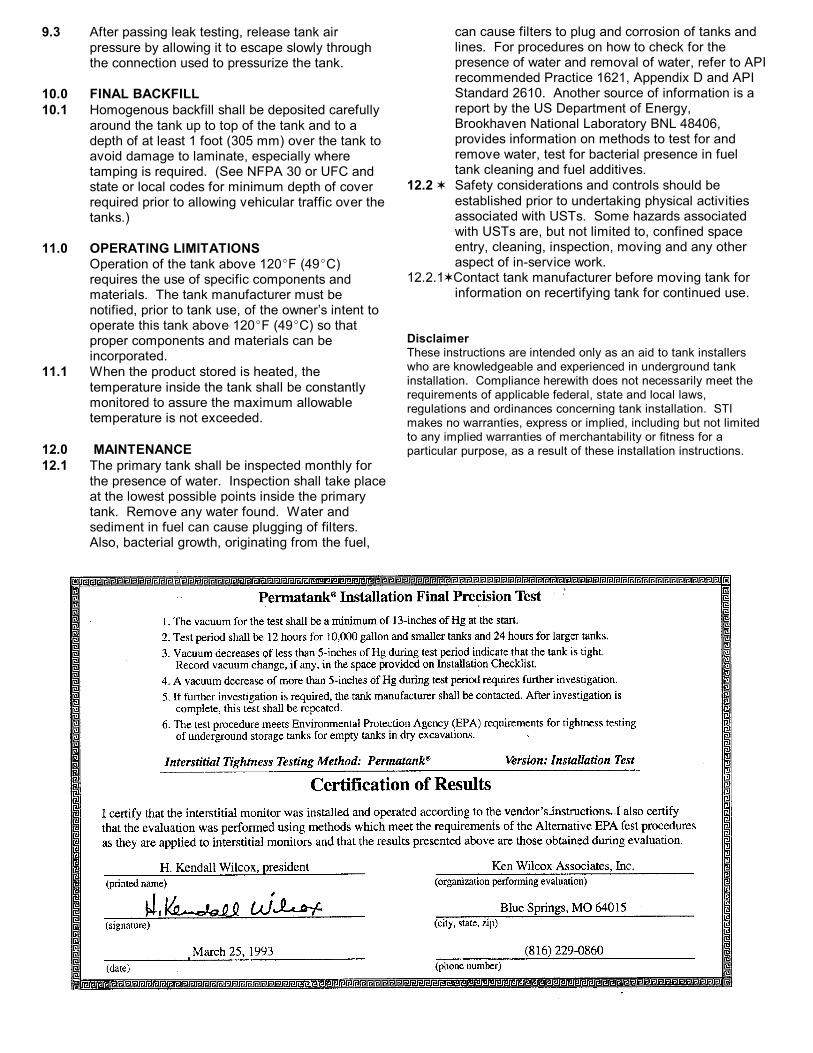
9.3 After passing leak testing, release tank airpressure by allowing it to escape slowly throughthe connection used to pressurize the tank.
10.0 FINAL BACKFILL10.1 Homogenous backfill shall be deposited carefully
around the tank up to top of the tank and to adepth of at least 1 foot (305 mm) over the tank toavoid damage to laminate, especially wheretamping is required. (See NFPA 30 or UFC andstate or local codes for minimum depth of coverrequired prior to allowing vehicular traffic over thetanks.)
11.0 OPERATING LIMITATIONSOperation of the tank above 120EF (49EC)requires the use of specific components andmaterials. The tank manufacturer must benotified, prior to tank use, of the owner’s intent tooperate this tank above 120EF (49EC) so thatproper components and materials can beincorporated.
11.1 When the product stored is heated, thetemperature inside the tank shall be constantlymonitored to assure the maximum allowabletemperature is not exceeded.
12.0 MAINTENANCE12.1 The primary tank shall be inspected monthly for
the presence of water. Inspection shall take placeat the lowest possible points inside the primarytank. Remove any water found. Water andsediment in fuel can cause plugging of filters. Also, bacterial growth, originating from the fuel,
can cause filters to plug and corrosion of tanks and lines. For procedures on how to check for thepresence of water and removal of water, refer to APIrecommended Practice 1621, Appendix D and APIStandard 2610. Another source of information is areport by the US Department of Energy,Brookhaven National Laboratory BNL 48406,provides information on methods to test for andremove water, test for bacterial presence in fueltank cleaning and fuel additives.
12.2 w Safety considerations and controls should beestablished prior to undertaking physical activitiesassociated with USTs. Some hazards associatedwith USTs are, but not limited to, confined spaceentry, cleaning, inspection, moving and any otheraspect of in-service work.
12.2.1wContact tank manufacturer before moving tank for information on recertifying tank for continued use.
DisclaimerThese instructions are intended only as an aid to tank installerswho are knowledgeable and experienced in underground tankinstallation. Compliance herewith does not necessarily meet therequirements of applicable federal, state and local laws,regulations and ordinances concerning tank installation. STImakes no warranties, express or implied, including but not limitedto any implied warranties of merchantability or fitness for aparticular purpose, as a result of these installation instructions.

FRP JACKETED STEEL
UNDERGROUND STORAGE TANKS
INSTALLATION CHECKLISTR923-01
570 Oakwood Road
Lake Zurich IL 60047
Phone: 847-438-8265
Fax: 847-438-8766
Note: This checklist includes certain key steps in the proper installation of a double wall steel underground storage tank with FRPsecondary containment and is intended only as an aid to tank installers who are knowledgeable and experienced in underground tankinstallation. Compliance herewith does not necessarily meet the requirements of all applicable federal, state and local laws, regulationsand ordinances concerning tank installation. TANK OWNER - A COPY OF THIS CHECKLIST SHOULD BE RETURNED TOYOU BY THE INSTALLER FOR RETENTION WITH YOUR PERMANENT RECORDS.
MAY 2001
This checklist must be completed by the installation contractor and returned to the tank owner.
Owner of Tank: Permatank Label No. ®
Location of Tank: Delivery Date: Tank Capacity: gallons(l)Installation Company: Diameter: feet(m); Length: feet (m)
Product to be stored:
! HANDLING- Lift equipment used - Lifting capacity Lbs.(Kg)- Type of chocks used if tank was stored - Describe any damage observed - Action taken
! EXCAVATION- Length Width Depth - Burial depth top of tank to grade inches(mm)- 18 inches (457 mm) minimum around each tank (Check when complete)- Burial depths meet minimum code requirements
(reference NFPA 30, UFC)NOTE: Check with tank manufacturer if burial depth exceeds 5feet.
! ANCHORING USED (Check One)Concrete Pad Deadman ORSoil and pavement overburden will hold do
(reference PEI/RP 100-90)- Number of hold-down straps Width inches(mm)- Protective pads used under straps
Protective pad at least 2 inches (50 mm) wider than width ofhold-down strap, or wrap around type pad used - 1 foot (304 mm) of backfill material under tank OR- 6 inch (152 mm) separation when concrete pad is used
! BACKFILL- Material: clean sand pea gravel #8 stone - Depth of homogenous material beneath tank inches- Backfill has been placed to ensure full support along the tank'sbottom quadrant
! TANK PIPING CONNECTION TEST- Pipe fittings air-tested at 5 psig (34.5 kPa) while applying soapsolution onto fittings to check for leaks
! INTERSTICE PRECISION TEST SYSTEM GAUGEREADINGS AT: Date:Tank Delivery inches (kPa) of Hg
Driver signature Installer signature D ate:
after backfill to tank top inches (kPa) of Hg after installation if completed inches (kPa) of Hg Other readings obtained inches (kPa) of Hg
(Signature of Installing Foreman or Project Engineer)
! PIPING USED (Check all that apply)Non-conductive Metallic Secondary containment used Flexible Was monitoring pipe extension installed?Yes No
(Signature of Installing Foreman or Project Engineer)
! COMMENTS:
TANK OWNER'S MAILING ADDRESS:Street City State Zip Telephone