Embed Size (px)
Citation preview

IZODOM 2000 POLSKA
98-220 Zduńska Wola, ul. Ceramiczna 2
tel. +48 43 823 41 88, +49 43 823 89 47, tel./fax +48 43 823 23 68 www.izodom2000polska.com e-mail: [email protected]
DESIGN AND CALCULATION GUIDELINES FOR FLOORS
OF IZODOM 2000 POLSKA SYSTEM
Floors IZODOM 2000 POLSKA /KJ
I. Floor for habitable building II. Other floor applications III. Construction details
Authors:
M.Sc. Jacek Filipczak M.Sc. Elżbieta Habiera M.Sc. Ewelina Kołodziejczyk
Verification: Prof. Maria Kamińska
Katedra Budownictwa Betonowego Politechniki Łódzkiej Department of Concrete Structures Technical University of Lodz
93 - 590 Łódź, Al. Politechniki 6, tel. (0-42) 631-35-75, fax. (0-42) 631-35-84
Lodz, May 2012
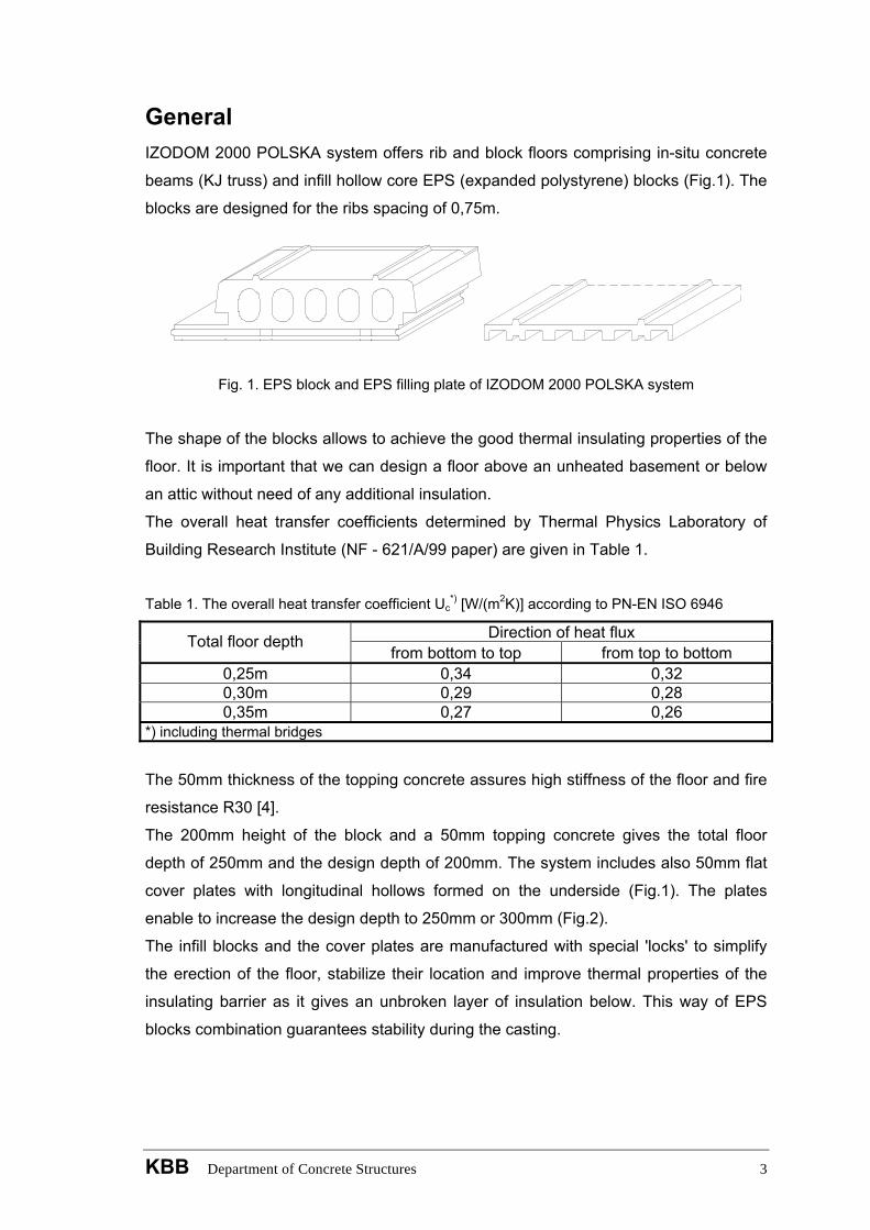
General IZODOM 2000 POLSKA system offers rib and block floors comprising in-situ concrete
beams (KJ truss) and infill hollow core EPS (expanded polystyrene) blocks (Fig.1). The
blocks are designed for the ribs spacing of 0,75m.
Fig. 1. EPS block and EPS filling plate of IZODOM 2000 POLSKA system
The shape of the blocks allows to achieve the good thermal insulating properties of the
floor. It is important that we can design a floor above an unheated basement or below
an attic without need of any additional insulation.
The overall heat transfer coefficients determined by Thermal Physics Laboratory of
Building Research Institute (NF - 621/A/99 paper) are given in Table 1.
Table 1. The overall heat transfer coefficient Uc
*) [W/(m2K)] according to PN-EN ISO 6946
Direction of heat flux Total floor depth from bottom to top from top to bottom
0,25m 0,34 0,32 0,30m 0,29 0,28 0,35m 0,27 0,26
*) including thermal bridges
The 50mm thickness of the topping concrete assures high stiffness of the floor and fire
resistance R30 [4].
The 200mm height of the block and a 50mm topping concrete gives the total floor
depth of 250mm and the design depth of 200mm. The system includes also 50mm flat
cover plates with longitudinal hollows formed on the underside (Fig.1). The plates
enable to increase the design depth to 250mm or 300mm (Fig.2).
The infill blocks and the cover plates are manufactured with special 'locks' to simplify
the erection of the floor, stabilize their location and improve thermal properties of the
insulating barrier as it gives an unbroken layer of insulation below. This way of EPS
blocks combination guarantees stability during the casting.
KBB Department of Concrete Structures 3
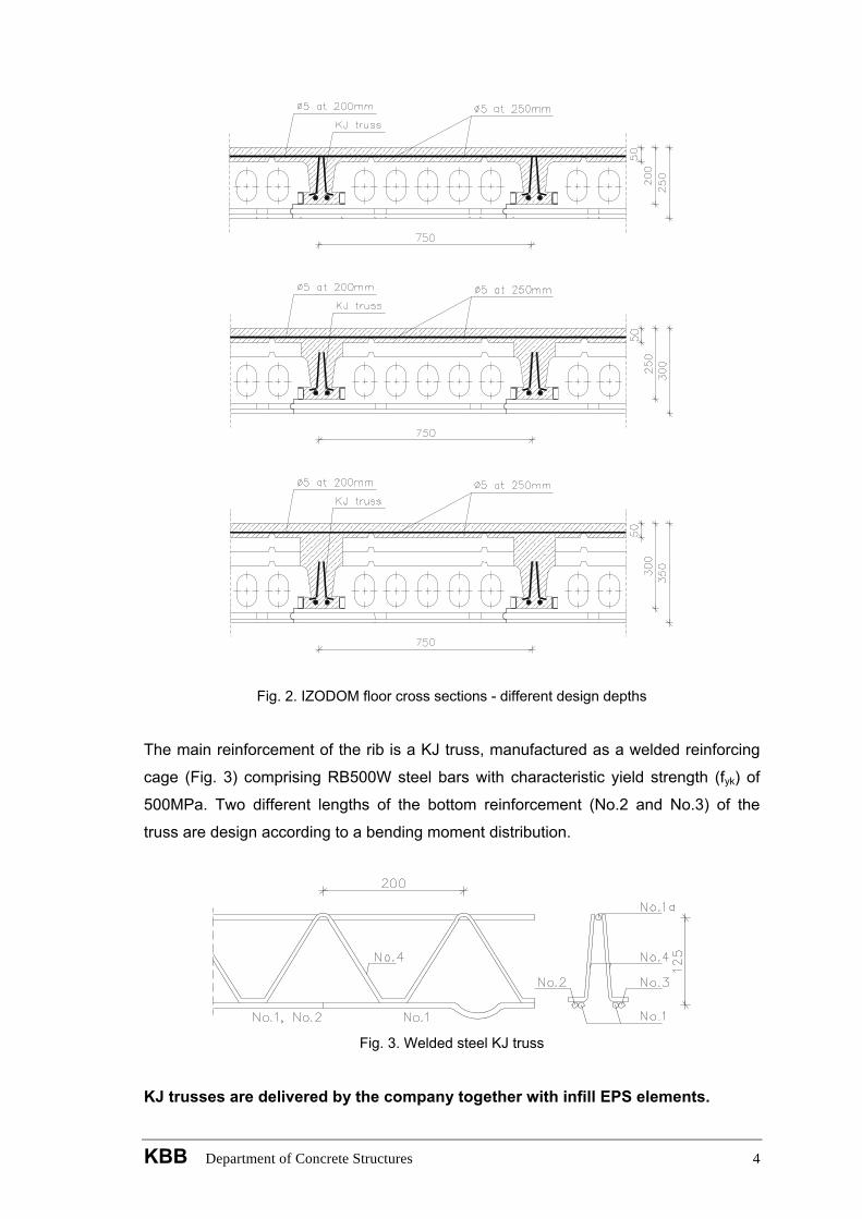
Fig. 2. IZODOM floor cross sections - different design depths
The main reinforcement of the rib is a KJ truss, manufactured as a welded reinforcing
cage (Fig. 3) comprising RB500W steel bars with characteristic yield strength (fyk) of
500MPa. Two different lengths of the bottom reinforcement (No.2 and No.3) of the
truss are design according to a bending moment distribution.
Fig. 3. Welded steel KJ truss
KJ trusses are delivered by the company together with infill EPS elements.
KBB Department of Concrete Structures 4
During concreting works, shuttering must be applied at joint of the hollow blocks along
the in-situ concrete ribs (look at p. III.4).
The main advantage of the floor is the large ribs spacing, equal to 0,75m that leads to
significant savings in time and cost. Furthermore, this type of the floor reduces much of
the site work. The prepared floor has a flat and smooth bottom surface what makes it
easy to finish. The ceiling can be finished with wallpapers, textured plaster, gypsum
boards or other materials.
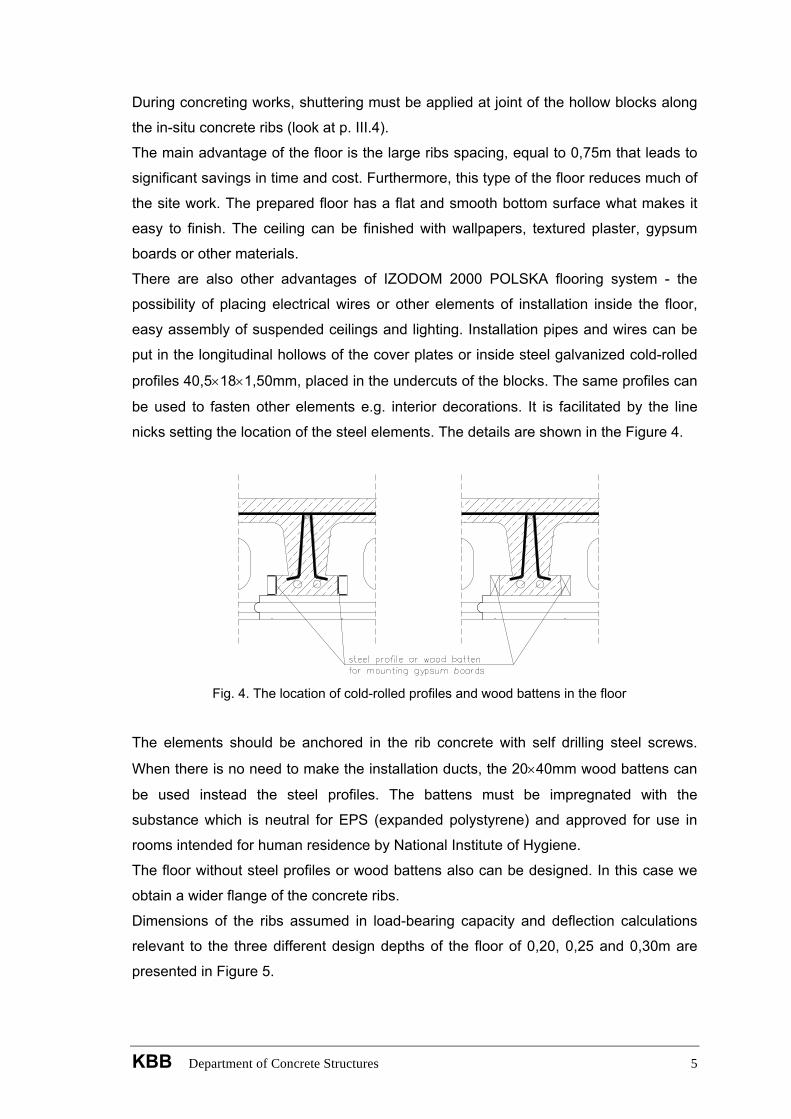
There are also other advantages of IZODOM 2000 POLSKA flooring system - the
possibility of placing electrical wires or other elements of installation inside the floor,
easy assembly of suspended ceilings and lighting. Installation pipes and wires can be
put in the longitudinal hollows of the cover plates or inside steel galvanized cold-rolled
profiles 40,5×18×1,50mm, placed in the undercuts of the blocks. The same profiles can
be used to fasten other elements e.g. interior decorations. It is facilitated by the line
nicks setting the location of the steel elements. The details are shown in the Figure 4.
Fig. 4. The location of cold-rolled profiles and wood battens in the floor
The elements should be anchored in the rib concrete with self drilling steel screws.
When there is no need to make the installation ducts, the 20×40mm wood battens can
be used instead the steel profiles. The battens must be impregnated with the
substance which is neutral for EPS (expanded polystyrene) and approved for use in
rooms intended for human residence by National Institute of Hygiene.
The floor without steel profiles or wood battens also can be designed. In this case we
obtain a wider flange of the concrete ribs.
Dimensions of the ribs assumed in load-bearing capacity and deflection calculations
relevant to the three different design depths of the floor of 0,20, 0,25 and 0,30m are
presented in Figure 5.
KBB Department of Concrete Structures 5
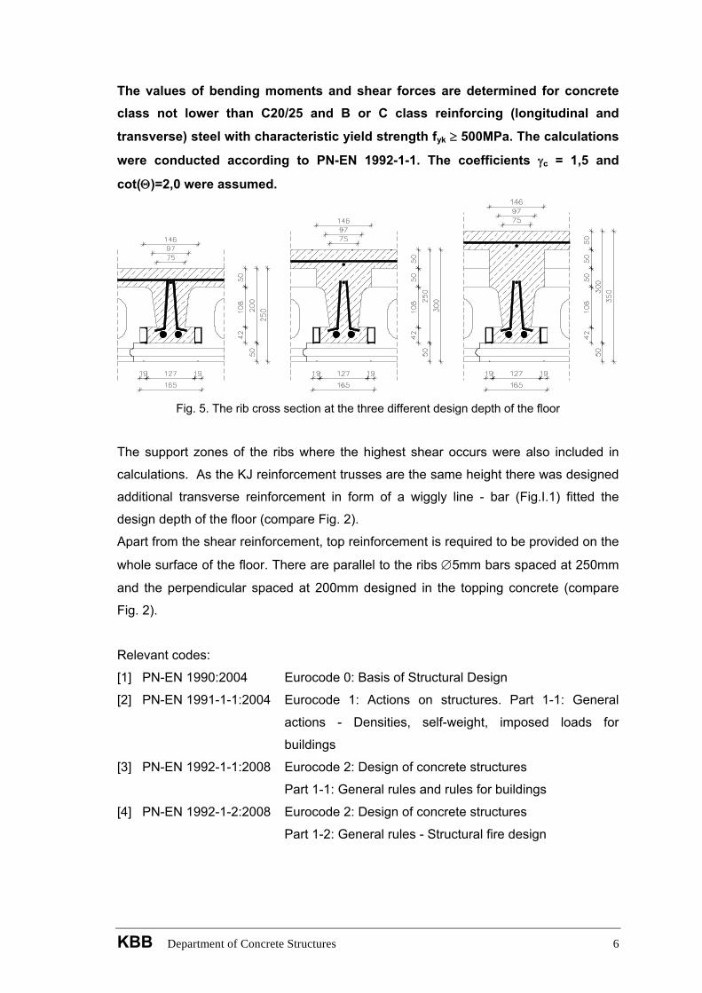
The values of bending moments and shear forces are determined for concrete class not lower than C20/25 and B or C class reinforcing (longitudinal and
transverse) steel with characteristic yield strength fyk ≥ 500MPa. The calculations
were conducted according to PN-EN 1992-1-1. The coefficients γc = 1,5 and
cot(Θ)=2,0 were assumed.
Fig. 5. The rib cross section at the three different design depth of the floor
The support zones of the ribs where the highest shear occurs were also included in
calculations. As the KJ reinforcement trusses are the same height there was designed
additional transverse reinforcement in form of a wiggly line - bar (Fig.I.1) fitted the
design depth of the floor (compare Fig. 2).
Apart from the shear reinforcement, top reinforcement is required to be provided on the
whole surface of the floor. There are parallel to the ribs ∅5mm bars spaced at 250mm
and the perpendicular spaced at 200mm designed in the topping concrete (compare
Fig. 2).
Relevant codes:
[1] PN-EN 1990:2004 Eurocode 0: Basis of Structural Design
[2] PN-EN 1991-1-1:2004 Eurocode 1: Actions on structures. Part 1-1: General
actions - Densities, self-weight, imposed loads for
buildings
[3] PN-EN 1992-1-1:2008 Eurocode 2: Design of concrete structures
Part 1-1: General rules and rules for buildings
[4] PN-EN 1992-1-2:2008 Eurocode 2: Design of concrete structures
Part 1-2: General rules - Structural fire design
KBB Department of Concrete Structures 6
I. Floor for habitable building For habitable building floor the following loads were assumed:
- floor finish materials 1,50kN/m2
- equivalent uniformly distributed load of movable partitions 0,50kN/m2
- live load 2,00kN/m2
The self-weight load of the floor depends on its total depth and it is given in the index
cards. It was assumed that each span length refers to a particular type of the
reinforcement truss, described in Table A. The design depth of the floor should be
determined on the basis of Table A for the design span length, defined as a length
between axes of the bearing walls.
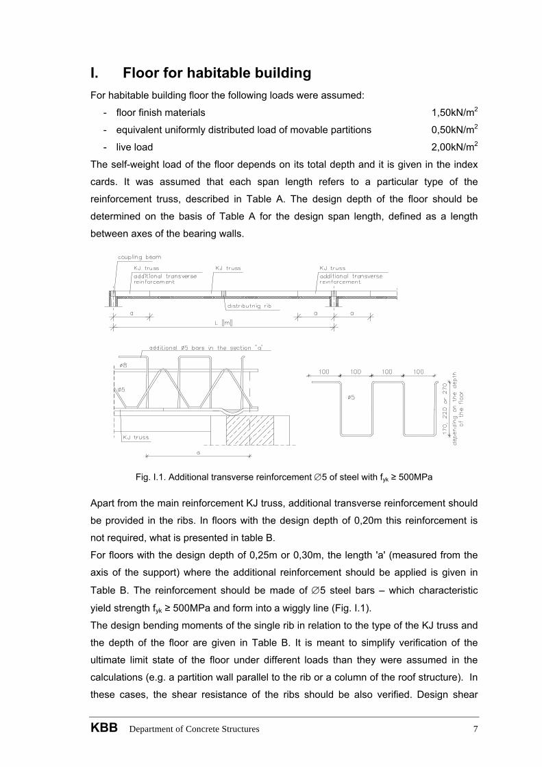
Fig. I.1. Additional transverse reinforcement ∅5 of steel with fyk ≥ 500MPa
Apart from the main reinforcement KJ truss, additional transverse reinforcement should
be provided in the ribs. In floors with the design depth of 0,20m this reinforcement is
not required, what is presented in table B.
For floors with the design depth of 0,25m or 0,30m, the length 'a' (measured from the
axis of the support) where the additional reinforcement should be applied is given in
Table B. The reinforcement should be made of ∅5 steel bars – which characteristic
yield strength fyk ≥ 500MPa and form into a wiggly line (Fig. I.1).
The design bending moments of the single rib in relation to the type of the KJ truss and
the depth of the floor are given in Table B. It is meant to simplify verification of the
ultimate limit state of the floor under different loads than they were assumed in the
calculations (e.g. a partition wall parallel to the rib or a column of the roof structure). In
these cases, the shear resistance of the ribs should be also verified. Design shear
KBB Department of Concrete Structures 7
force in a rib section can not exceed the value VRd,max defined as the design value
limited by crushing of the compression struts. In regions of the member where VEd is
higher than VRd,c (the design shear resistance of the member without shear
reinforcement, Table I.1) calculated shear reinforcement is necessary. The cross-
sectional area of the shear reinforcement and the spacing of the stirrups can be taken
(to satisfy VEd ≤ VRd,s condition) according to Table I.1.
The range of transverse reinforcement (from the axis of the support) under constant
lateral load q’ = 0,75qEd [kN/m] can be calculated from:
2L
VVV
aEd
c,RdEd ⋅−
= , where: 2L'qVEd ⋅=
but for different kind of a load the distance should be determined according to a shear
force graph. Table I.1. The design values VRd for a single rib
Design floor depth VRd Reinforcement 0,20m 0,25m 0,30m
VRd,c kN / rib
the main bottom bars of the truss (bars No. 1) ∅6 ∅8 ∅10
6,56 7,96 9,25
7,46 9,05 10,52
8,12 9,85 11,45
VRd,s kN / beam
the transverse reinforcement of the truss additional ∅5 at 100mm
30,82
-
-
35,30
-
42,97
VRd,max kN / rib 35,77 45,70 55,64
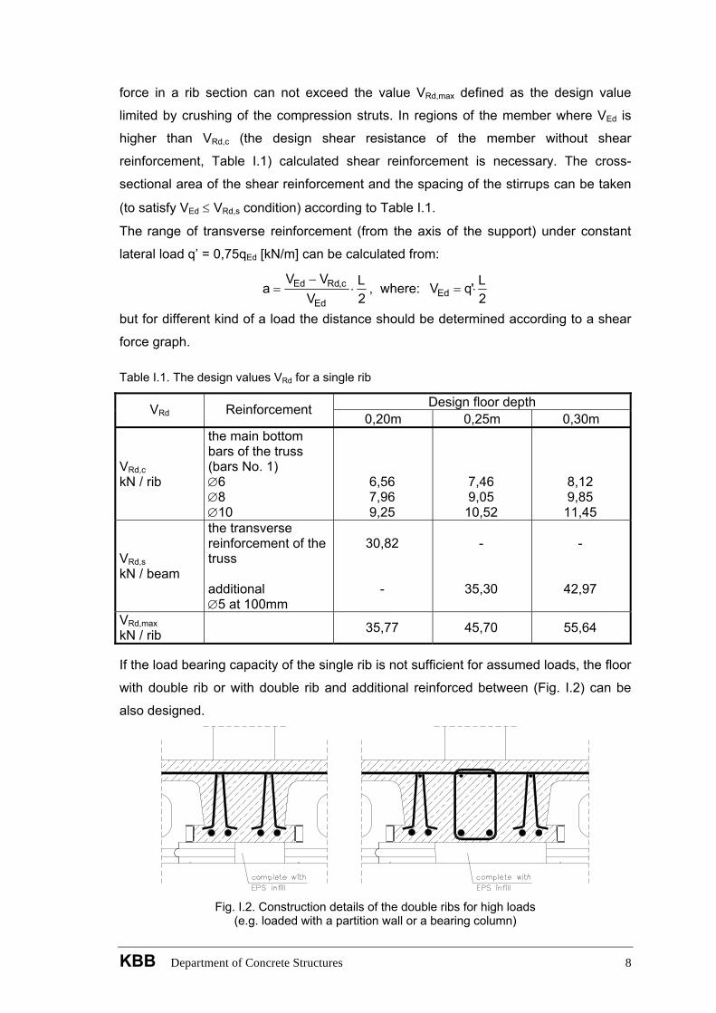
If the load bearing capacity of the single rib is not sufficient for assumed loads, the floor
with double rib or with double rib and additional reinforced between (Fig. I.2) can be
also designed.
Fig. I.2. Construction details of the double ribs for high loads
(e.g. loaded with a partition wall or a bearing column)
KBB Department of Concrete Structures 8
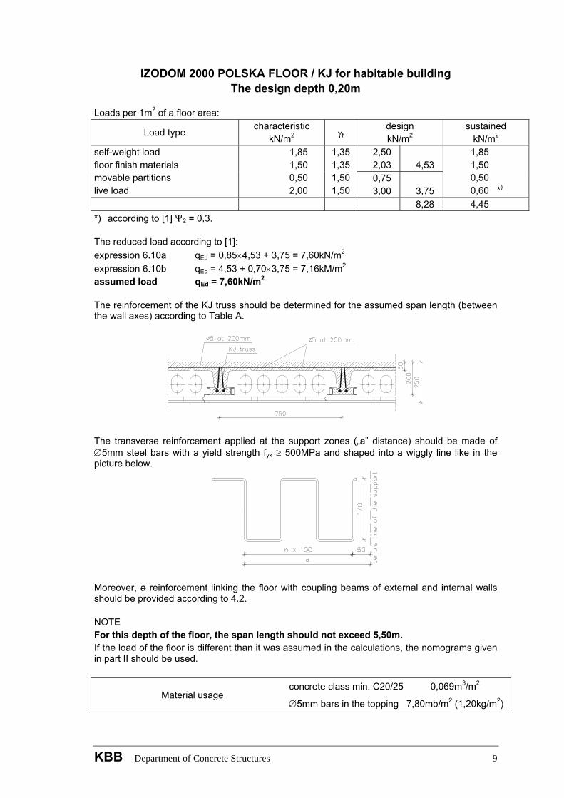
IZODOM 2000 POLSKA FLOOR / KJ for habitable building The design depth 0,20m
Loads per 1m2 of a floor area:
Load type characteristic
kN/m2 γf design kN/m2
sustained kN/m2
2,50 2,03
4,53
self-weight load floor finish materials movable partitions live load
1,85 1,50 0,50 2,00
1,35 1,35 1,50 1,50
0,75 3,00
3,75
1,85 1,50 0,50 0,60 *)
8,28 4,45 *) according to [1] Ψ2 = 0,3. The reduced load according to [1]: expression 6.10a qEd = 0,85×4,53 + 3,75 = 7,60kN/m2 expression 6.10b qEd = 4,53 + 0,70×3,75 = 7,16kM/m2 assumed load qEd = 7,60kN/m2 The reinforcement of the KJ truss should be determined for the assumed span length (between the wall axes) according to Table A.
The transverse reinforcement applied at the support zones („a” distance) should be made of ∅5mm steel bars with a yield strength fyk ≥ 500MPa and shaped into a wiggly line like in the picture below.
Moreover, a reinforcement linking the floor with coupling beams of external and internal walls should be provided according to 4.2. NOTE For this depth of the floor, the span length should not exceed 5,50m. If the load of the floor is different than it was assumed in the calculations, the nomograms given in part II should be used.
Material usage concrete class min. C20/25 0,069m3/m2
∅5mm bars in the topping 7,80mb/m2 (1,20kg/m2)
KBB Department of Concrete Structures 9
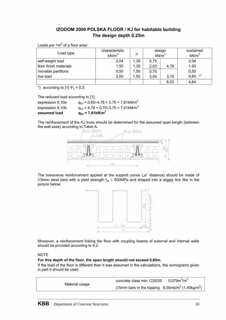
IZODOM 2000 POLSKA FLOOR / KJ for habitable building The design depth 0,25m
Loads per 1m2 of a floor area:
Load type characteristic
kN/m2 γf design kN/m2
sustained kN/m2
2,75 2,03
4,78
self-weight load floor finish materials movable partitions live load
2,04 1,50 0,50 2,00
1,35 1,35 1,50 1,50
0,75 3,00
3,75
2,04 1,50 0,50 0,60 *)
8,53 4,64 *) according to [1] Ψ2 = 0,3. The reduced load according to [1]: expression 6.10a qEd = 0,85×4,78 + 3,75 = 7,81kN/m2 expression 6.10b qEd = 4,78 + 0,70×3,75 = 7,41kM/m2 assumed load qEd = 7,81kN/m2 The reinforcement of the KJ truss should be determined for the assumed span length (between the wall axes) according to Table A.
The transverse reinforcement applied at the support zones („a” distance) should be made of ∅5mm steel bars with a yield strength fyk ≥ 500MPa and shaped into a wiggly line like in the picture below.
Moreover, a reinforcement linking the floor with coupling beams of external and internal walls should be provided according to 4.2. NOTE For this depth of the floor, the span length should not exceed 6,60m. If the load of the floor is different than it was assumed in the calculations, the nomograms given in part II should be used.
Material usage concrete class min. C20/25 0,079m3/m2
∅5mm bars in the topping 9,00mb/m2 (1,40kg/m2)
KBB Department of Concrete Structures 10

IZODOM 2000 POLSKA FLOOR / KJ for habitable building The design depth 0,30m
Loads per 1m2 of a floor area:
Load type characteristic
kN/m2 γf design kN/m2
sustained kN/m2
3,09 2,03
5,12
self-weight load floor finish materials movable partitions live load
2,29 1,50 0,50 2,00
1,35 1,35 1,50 1,50
0,75 3,00
3,75
2,29 1,50 0,50 0,60 *)
8,87 4,89 *) according to [1] Ψ2 = 0,3. The reduced load according to [1]: expression 6.10a qEd = 0,85×5,12 + 3,75 = 8,10kN/m2 expression 6.10b qEd = 5,12 + 0,70×3,75 = 7,75kM/m2 assumed load qEd = 8,10kN/m2 The reinforcement of the KJ truss should be determined for the assumed span length (between the wall axes) according to Table A.
The transverse reinforcement applied at the support zones („a” distance) should be made of ∅5mm steel bars with a yield strength fyk ≥ 500MPa and shaped into a wiggly line like in the picture below.
Moreover, a reinforcement linking the floor with coupling beams of external and internal walls should be provided according to 4.2. NOTE For this depth of the floor, the span length should not exceed 7,80m. If the load of the floor is different than it was assumed in the calculations, the nomograms given in part II should be used.
Material usage concrete class min. C20/25 0,089m3/m2 ∅5mm bars In the topping 9,00mb/m2 (1,40kg/m2)
KBB Department of Concrete Structures 11
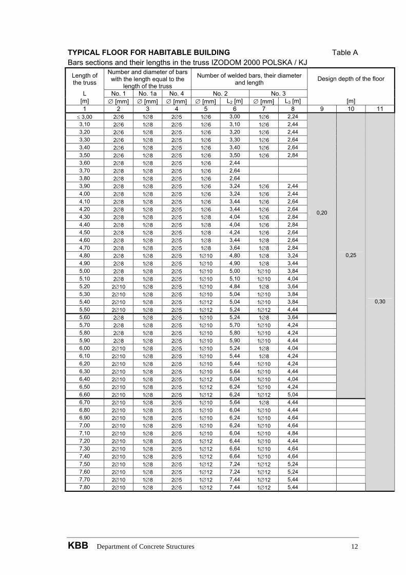
TYPICAL FLOOR FOR HABITABLE BUILDING Table A Bars sections and their lengths in the truss IZODOM 2000 POLSKA / KJ
Length of the truss
Number and diameter of bars with the length equal to the
length of the truss
Number of welded bars, their diameter and length
L No. 1 No. 1a No. 4 No. 2 No. 3
Design depth of the floor
[m] ∅ [mm] ∅ [mm] ∅ [mm] ∅ [mm] L2 [m] ∅ [mm] L3 [m] [m] 1 2 3 4 5 6 7 8 9 10 11
≤ 3,00 2∅6 1∅8 2∅5 1∅6 3,00 1∅6 2,24 3,10 2∅6 1∅8 2∅5 1∅6 3,10 1∅6 2,44 3,20 2∅6 1∅8 2∅5 1∅6 3,20 1∅6 2,44 3,30 2∅6 1∅8 2∅5 1∅6 3,30 1∅6 2,64 3,40 2∅6 1∅8 2∅5 1∅6 3,40 1∅6 2,64 3,50 2∅6 1∅8 2∅5 1∅6 3,50 1∅6 2,84 3,60 2∅8 1∅8 2∅5 1∅6 2,44 3,70 2∅8 1∅8 2∅5 1∅6 2,64 3,80 2∅8 1∅8 2∅5 1∅6 2,64 3,90 2∅8 1∅8 2∅5 1∅6 3,24 1∅6 2,44 4,00 2∅8 1∅8 2∅5 1∅6 3,24 1∅6 2,44 4,10 2∅8 1∅8 2∅5 1∅6 3,44 1∅6 2,64 4,20 2∅8 1∅8 2∅5 1∅6 3,44 1∅6 2,64 4,30 2∅8 1∅8 2∅5 1∅8 4,04 1∅6 2,84 4,40 2∅8 1∅8 2∅5 1∅8 4,04 1∅6 2,84 4,50 2∅8 1∅8 2∅5 1∅8 4,24 1∅6 2,64 4,60 2∅8 1∅8 2∅5 1∅8 3,44 1∅8 2,64 4,70 2∅8 1∅8 2∅5 1∅8 3,64 1∅8 2,84 4,80 2∅8 1∅8 2∅5 1∅10 4,80 1∅8 3,24 4,90 2∅8 1∅8 2∅5 1∅10 4,90 1∅8 3,44 5,00 2∅8 1∅8 2∅5 1∅10 5,00 1∅10 3,84 5,10 2∅8 1∅8 2∅5 1∅10 5,10 1∅10 4,04 5,20 2∅10 1∅8 2∅5 1∅10 4,84 1∅8 3,64 5,30 2∅10 1∅8 2∅5 1∅10 5,04 1∅10 3,84 5,40 2∅10 1∅8 2∅5 1∅12 5,04 1∅10 3,84 5,50 2∅10 1∅8 2∅5 1∅12 5,24 1∅12 4,44
0,20
5,60 2∅8 1∅8 2∅5 1∅10 5,24 1∅8 3,64 5,70 2∅8 1∅8 2∅5 1∅10 5,70 1∅10 4,24 5,80 2∅8 1∅8 2∅5 1∅10 5,80 1∅10 4,24 5,90 2∅8 1∅8 2∅5 1∅10 5,90 1∅10 4,44 6,00 2∅10 1∅8 2∅5 1∅10 5,24 1∅8 4,04 6,10 2∅10 1∅8 2∅5 1∅10 5,44 1∅8 4,24 6,20 2∅10 1∅8 2∅5 1∅10 5,44 1∅10 4,24 6,30 2∅10 1∅8 2∅5 1∅10 5,64 1∅10 4,44 6,40 2∅10 1∅8 2∅5 1∅12 6,04 1∅10 4,04 6,50 2∅10 1∅8 2∅5 1∅12 6,24 1∅10 4,24 6,60 2∅10 1∅8 2∅5 1∅12 6,24 1∅12 5,04
0,25
6,70 2∅10 1∅8 2∅5 1∅10 5,64 1∅8 4,44 6,80 2∅10 1∅8 2∅5 1∅10 6,04 1∅10 4,44 6,90 2∅10 1∅8 2∅5 1∅10 6,24 1∅10 4,64 7,00 2∅10 1∅8 2∅5 1∅10 6,24 1∅10 4,64 7,10 2∅10 1∅8 2∅5 1∅10 6,04 1∅10 4,84 7,20 2∅10 1∅8 2∅5 1∅12 6,44 1∅10 4,44 7,30 2∅10 1∅8 2∅5 1∅12 6,64 1∅10 4,64 7,40 2∅10 1∅8 2∅5 1∅12 6,64 1∅10 4,64 7,50 2∅10 1∅8 2∅5 1∅12 7,24 1∅12 5,24 7,60 2∅10 1∅8 2∅5 1∅12 7,24 1∅12 5,24 7,70 2∅10 1∅8 2∅5 1∅12 7,44 1∅12 5,44 7,80 2∅10 1∅8 2∅5 1∅12 7,44 1∅12 5,44
0,30
KBB Department of Concrete Structures 12
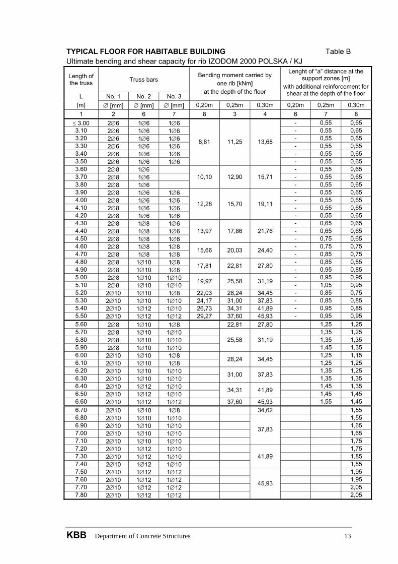
TYPICAL FLOOR FOR HABITABLE BUILDING Table B Ultimate bending and shear capacity for rib IZODOM 2000 POLSKA / KJ
Length of the truss
Truss bars
L No. 1 No. 2 No. 3
Bending moment carried by one rib [kNm]
at the depth of the floor
Lenght of “a” distance at the support zones [m]
with additional reinforcement for shear at the depth of the floor
[m] ∅ [mm] ∅ [mm] ∅ [mm] 0,20m 0,25m 0,30m 0,20m 0,25m 0,30m 1 2 6 7 8 3 4 6 7 8
≤ 3.00 2∅6 1∅6 1∅6 - 0,55 0,65 3.10 2∅6 1∅6 1∅6 - 0,55 0,65 3.20 2∅6 1∅6 1∅6 - 0,55 0,65 3.30 2∅6 1∅6 1∅6 - 0,55 0,65 3.40 2∅6 1∅6 1∅6 - 0,55 0,65 3.50 2∅6 1∅6 1∅6
8,81 11,25 13,68
- 0,55 0,65 3.60 2∅8 1∅6 - 0,55 0,65 3.70 2∅8 1∅6 - 0,55 0,65 3.80 2∅8 1∅6
10,10 12,90 15,71 - 0,55 0,65
3.90 2∅8 1∅6 1∅6 - 0,55 0,65 4.00 2∅8 1∅6 1∅6 - 0,55 0,65 4.10 2∅8 1∅6 1∅6 - 0,55 0,65 4.20 2∅8 1∅6 1∅6
12,28 15,70 19,11
- 0,55 0,65 4.30 2∅8 1∅8 1∅6 - 0,65 0,65 4.40 2∅8 1∅8 1∅6 - 0,65 0,65 4.50 2∅8 1∅8 1∅6
13,97 17,86 21,76 - 0,75 0,65
4.60 2∅8 1∅8 1∅8 - 0,75 0,75 4.70 2∅8 1∅8 1∅8
15,66 20,03 24,40 - 0,85 0,75 4.80 2∅8 1∅10 1∅8 - 0,85 0,85 4.90 2∅8 1∅10 1∅8
17,81 22,81 27,80 - 0,95 0,85 5.00 2∅8 1∅10 1∅10 - 0,95 0,95 5.10 2∅8 1∅10 1∅10
19,97 25,58 31,19 - 1,05 0,95 5.20 2∅10 1∅10 1∅8 22,03 28,24 34,45 - 0,85 0,75 5.30 2∅10 1∅10 1∅10 24,17 31,00 37,83 - 0,85 0,85 5.40 2∅10 1∅12 1∅10 26,73 34,31 41,89 - 0,95 0,85 5.50 2∅10 1∅12 1∅12 29,27 37,60 45,93 - 0,95 0,95 5.60 2∅8 1∅10 1∅8 22,81 27,80 1,25 1,25 5.70 2∅8 1∅10 1∅10 1,35 1,25 5.80 2∅8 1∅10 1∅10 1,35 1,35 5.90 2∅8 1∅10 1∅10
25,58 31,19 1,45 1,35
6.00 2∅10 1∅10 1∅8 1,25 1,15 6.10 2∅10 1∅10 1∅8
28,24 34,45 1,25 1,25 6.20 2∅10 1∅10 1∅10 1,35 1,25 6.30 2∅10 1∅10 1∅10
31,00 37,83 1,35 1,35 6.40 2∅10 1∅12 1∅10 1,45 1,35 6.50 2∅10 1∅12 1∅10
34,31 41,89 1,45 1,45 6.60 2∅10 1∅12 1∅12 37,60 45,93 1,55 1,45 6.70 2∅10 1∅10 1∅8 34,62 1,55 6.80 2∅10 1∅10 1∅10 1,55 6.90 2∅10 1∅10 1∅10 1,65 7.00 2∅10 1∅10 1∅10 1,65 7.10 2∅10 1∅10 1∅10
37,83
1,75 7.20 2∅10 1∅12 1∅10 1,75 7.30 2∅10 1∅12 1∅10 1,85 7.40 2∅10 1∅12 1∅10
41,89 1,85
7.50 2∅10 1∅12 1∅12 1,95 7.60 2∅10 1∅12 1∅12 1,95 7.70 2∅10 1∅12 1∅12 2,05 7.80 2∅10 1∅12 1∅12
45,93
2,05
KBB Department of Concrete Structures 13
II. Other floor applications The design depth of the floor and the main reinforcement should be determined
pursuant to appropriate nomograms.
Nomograms were prepared assuming:
- KJ truss as a ribs reinforcement,
- concrete class C20/25,
- the span of the floor between the wall axes from 3,0 to 7,8m.
Nomograms concern the two issues – load capacity and deflections. Nomograms allow
to determine required main reinforcement, i.e. choose an appropriate KJ truss with a
fixed longitudinal reinforcement. Permissible deflection of the floor is taken as L/250 or
L/500, selectable by the designer and investor, and depends on the objects function.
After selecting the depth of the floor, the expected total design load and characteristic
sustained load of the floor must be specified. Then on the basis of the appriopriate
nomograms the required main reinforcement of the ribs must be selected.
If the floor has two or more spans, additional ∅12 ribbed steel bars should be used
over the support, one for each floor beam. This top reinforcement should extend at
least 1/3 the length of the span, measured from the face of the support.
The range of the additional transverse ribs reinforcement and diameter of the bars
should be set using the values specified in the Table II.1 and the relationships as in
point I.
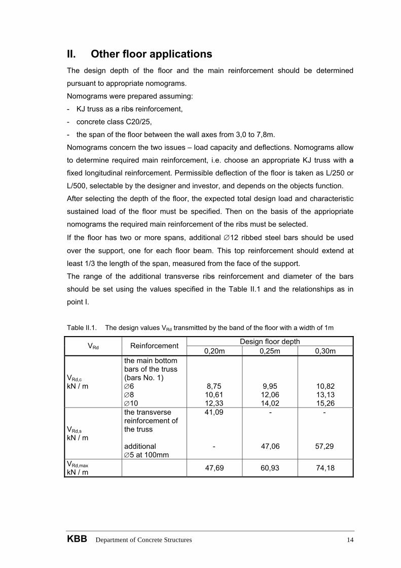
Table II.1. The design values VRd transmitted by the band of the floor with a width of 1m
Design floor depth VRd Reinforcement 0,20m 0,25m 0,30m
VRd,c kN / m
the main bottom bars of the truss (bars No. 1) ∅6 ∅8 ∅10
8,75 10,61 12,33
9,95 12,06 14,02
10,82 13,13 15,26
VRd,s kN / m
the transverse reinforcement of the truss additional ∅5 at 100mm
41,09 -
-
47,06
-
57,29
VRd,max kN / m 47,69 60,93 74,18
KBB Department of Concrete Structures 14
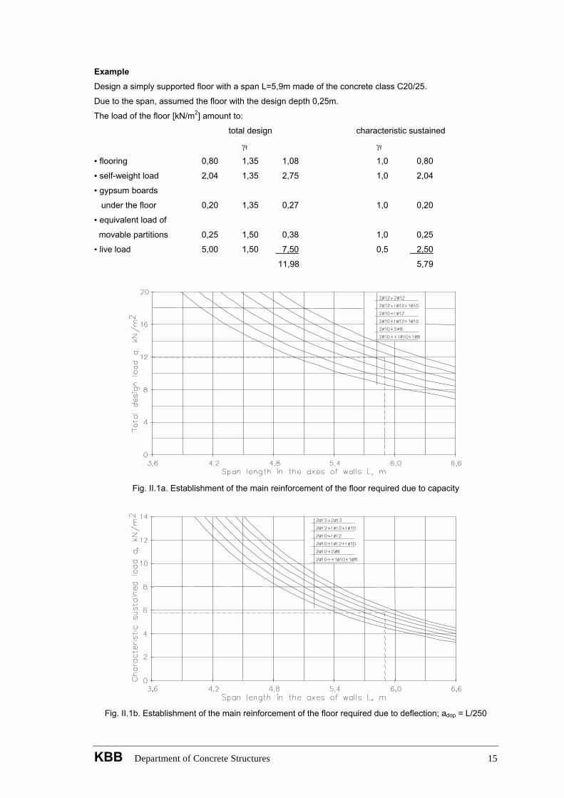
Example Design a simply supported floor with a span L=5,9m made of the concrete class C20/25.
Due to the span, assumed the floor with the design depth 0,25m.
The load of the floor [kN/m2] amount to:
total design characteristic sustained
γf γf
▪ flooring 0,80 1,35 1,08 1,0 0,80
▪ self-weight load 2,04 1,35 2,75 1,0 2,04
▪ gypsum boards
under the floor 0,20 1,35 0,27 1,0 0,20
▪ equivalent load of
movable partitions 0,25 1,50 0,38 1,0 0,25
▪ live load 5,00 1,50 7,50 0,5 2,50
11,98 5,79
Fig. II.1a. Establishment of the main reinforcement of the floor required due to capacity
Fig. II.1b. Establishment of the main reinforcement of the floor required due to deflection; adop = L/250
KBB Department of Concrete Structures 15
From the nomogram for the floor with the design depth h=0,25m (Fig. II.1a) can be read that due to the
load capacity is needed 2∅12 + 1∅12 +1∅10 reinforcement, with a total cross-sectional area
ΣAs=4,17cm2.
Due to the deflection, at the allowable deflection L/250 (Fig. II.1b), the same bottom truss reinforcement
2∅12 + 1∅12 + 1∅10 (As=4,17cm2) is required.
The floor with a design depth h =0,25m can not satisfy a condition of permissible deflection equal to L/500.
The design transverse force follow from:
m/kN34,352
9,598,112
qLVEd =⋅
==
and does not exceed VRd,max=60,93kN/m (Table II.1), therefore for VRd,c=14,02kN/m (table II.1, h=0,25m,
bottom main reinforcement ∅10mm), the transverse reinforcement is required in sections of length:
m78,129,5
34,3502,1434,35a =⋅
−=
In these sections on both supports the transverse reinforcement of the truss should be completed as it
shown in the Fig. I.1. On the basis of the table II.1 we assume the transverse reinforcement ∅5 at 100mm,
for which VRd,s=47,06kN/m > VEd=35,34kN/m.
KBB Department of Concrete Structures 16
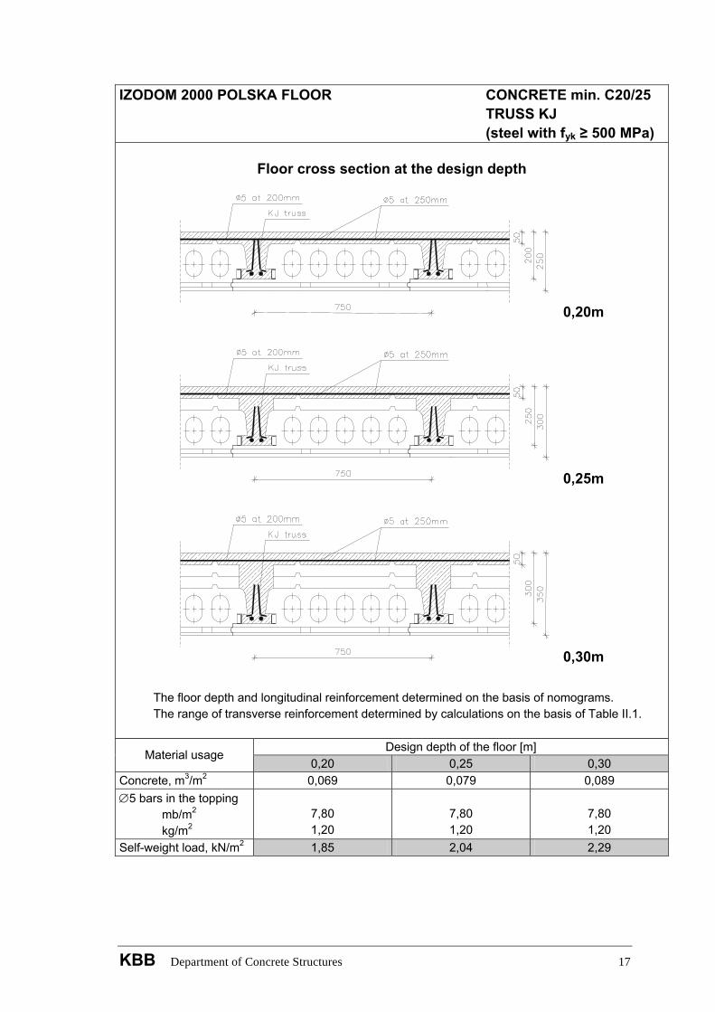
IZODOM 2000 POLSKA FLOOR CONCRETE min. C20/25 TRUSS KJ (steel with fyk ≥ 500 MPa)
Floor cross section at the design depth
0,20m
0,25m
0,30m
The floor depth and longitudinal reinforcement determined on the basis of nomograms. The range of transverse reinforcement determined by calculations on the basis of Table II.1.
Design depth of the floor [m]
Material usage 0,20 0,25 0,30
Concrete, m3/m2 0,069 0,079 0,089 ∅5 bars in the topping mb/m2 kg/m2
7,80 1,20
7,80 1,20
7,80 1,20
Self-weight load, kN/m2 1,85 2,04 2,29
KBB Department of Concrete Structures 17
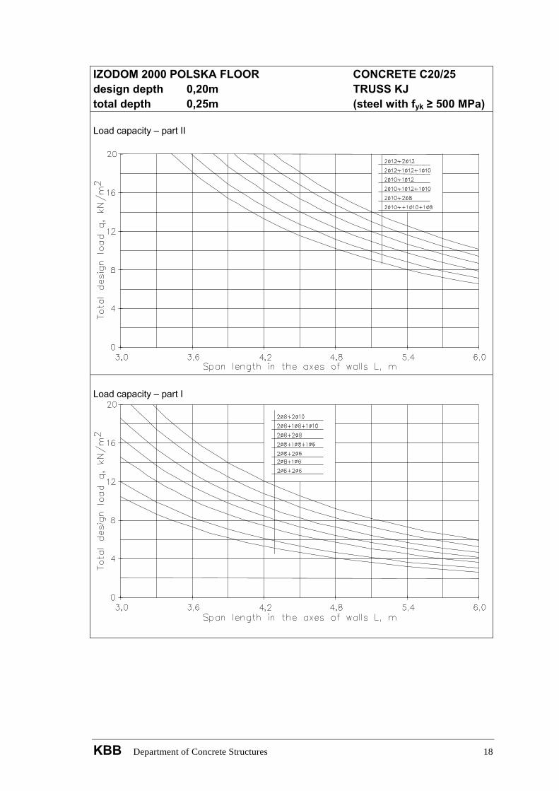
IZODOM 2000 POLSKA FLOOR CONCRETE C20/25 design depth 0,20m TRUSS KJ total depth 0,25m (steel with fyk ≥ 500 MPa) Load capacity – part II
Load capacity – part I
KBB Department of Concrete Structures 18
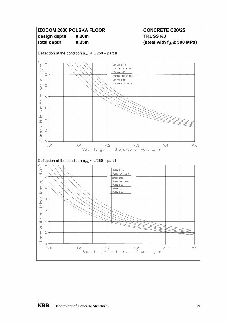
IZODOM 2000 POLSKA FLOOR CONCRETE C20/25 design depth 0,20m TRUSS KJ total depth 0,25m (steel with fyk ≥ 500 MPa) Deflection at the condition adop < L/250 – part II
Deflection at the condition adop < L/250 – part I
KBB Department of Concrete Structures 19
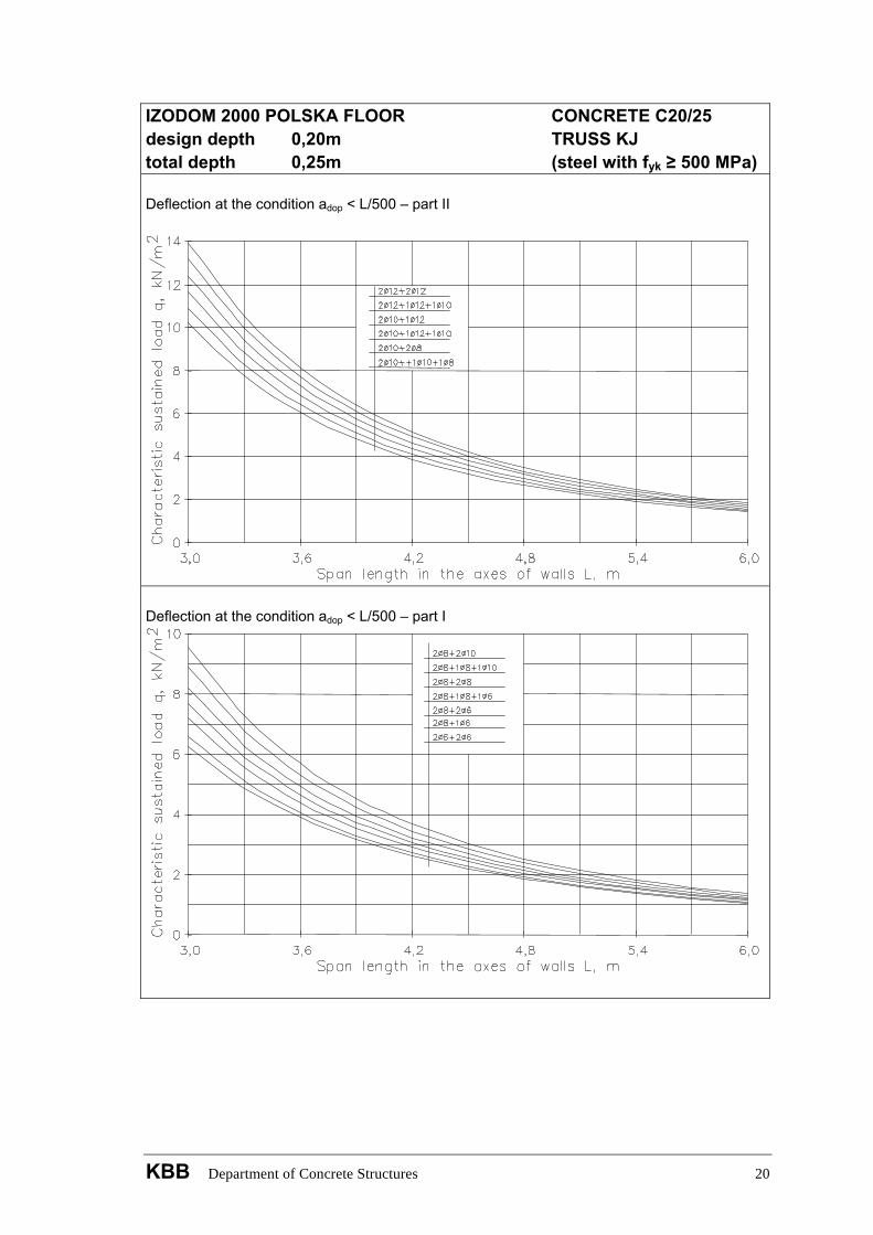
IZODOM 2000 POLSKA FLOOR CONCRETE C20/25 design depth 0,20m TRUSS KJ total depth 0,25m (steel with fyk ≥ 500 MPa) Deflection at the condition adop < L/500 – part II
Deflection at the condition adop < L/500 – part I
KBB Department of Concrete Structures 20
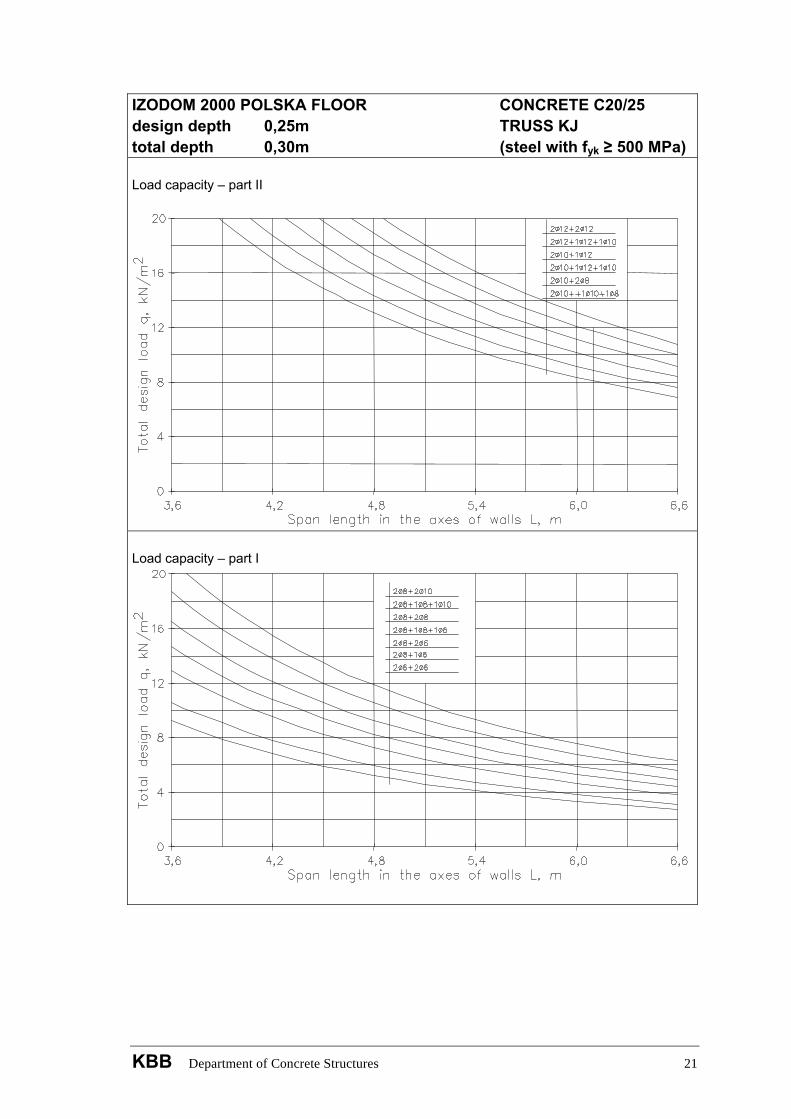
IZODOM 2000 POLSKA FLOOR CONCRETE C20/25 design depth 0,25m TRUSS KJ total depth 0,30m (steel with fyk ≥ 500 MPa) Load capacity – part II
Load capacity – part I
KBB Department of Concrete Structures 21
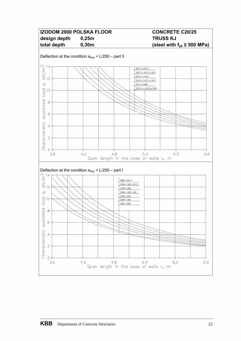
IZODOM 2000 POLSKA FLOOR CONCRETE C20/25 design depth 0,25m TRUSS KJ total depth 0,30m (steel with fyk ≥ 500 MPa) Deflection at the condition adop < L/250 – part II
Deflection at the condition adop < L/250 – part I
KBB Department of Concrete Structures 22
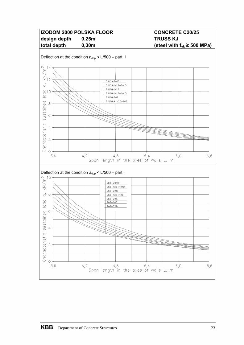
IZODOM 2000 POLSKA FLOOR CONCRETE C20/25 design depth 0,25m TRUSS KJ total depth 0,30m (steel with fyk ≥ 500 MPa) Deflection at the condition adop < L/500 – part II
Deflection at the condition adop < L/500 – part I
KBB Department of Concrete Structures 23
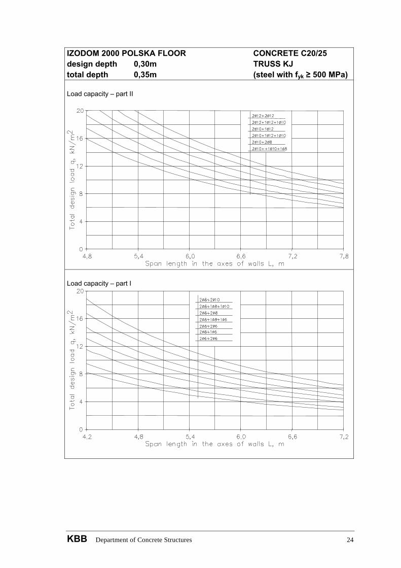
IZODOM 2000 POLSKA FLOOR CONCRETE C20/25 design depth 0,30m TRUSS KJ total depth 0,35m (steel with fyk ≥ 500 MPa) Load capacity – part II
Load capacity – part I
KBB Department of Concrete Structures 24

IZODOM 2000 POLSKA FLOOR CONCRETE C20/25 design depth 0,30m TRUSS KJ total depth 0,35m (steel with fyk ≥ 500 MPa) Deflection at the condition adop < L/250 – part II
Deflection at the condition adop < L/250 – part I
KBB Department of Concrete Structures 25
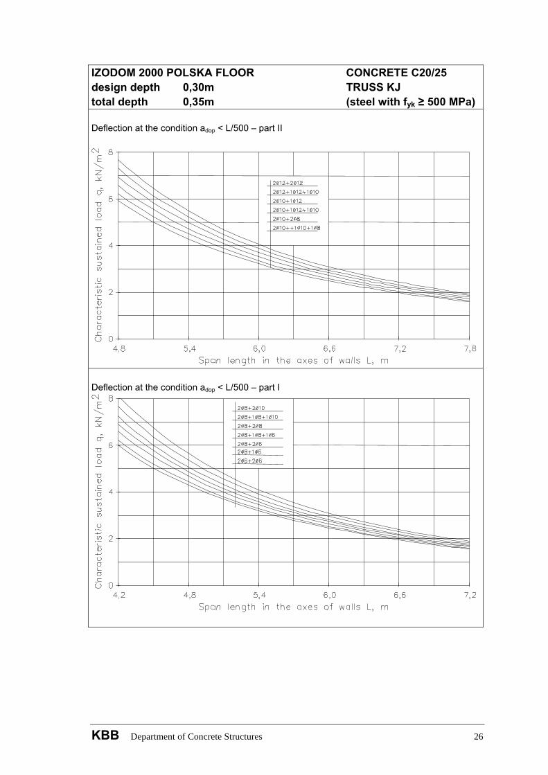
IZODOM 2000 POLSKA FLOOR CONCRETE C20/25 design depth 0,30m TRUSS KJ total depth 0,35m (steel with fyk ≥ 500 MPa) Deflection at the condition adop < L/500 – part II
Deflection at the condition adop < L/500 – part I
KBB Department of Concrete Structures 26
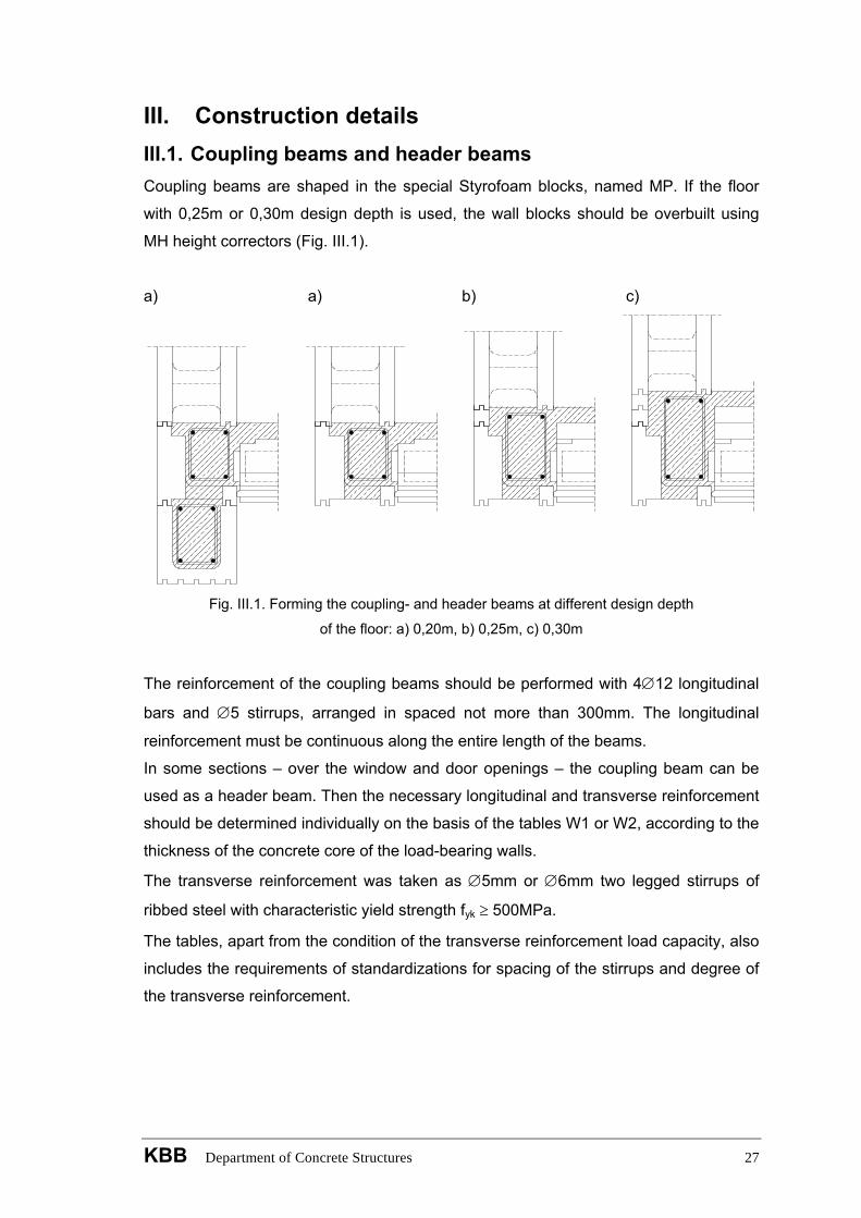
III. Construction details III.1. Coupling beams and header beams Coupling beams are shaped in the special Styrofoam blocks, named MP. If the floor
with 0,25m or 0,30m design depth is used, the wall blocks should be overbuilt using
MH height correctors (Fig. III.1).
a) a) b) c)
Fig. III.1. Forming the coupling- and header beams at different design depth
of the floor: a) 0,20m, b) 0,25m, c) 0,30m
The reinforcement of the coupling beams should be performed with 4∅12 longitudinal
bars and ∅5 stirrups, arranged in spaced not more than 300mm. The longitudinal
reinforcement must be continuous along the entire length of the beams.
In some sections – over the window and door openings – the coupling beam can be
used as a header beam. Then the necessary longitudinal and transverse reinforcement
should be determined individually on the basis of the tables W1 or W2, according to the
thickness of the concrete core of the load-bearing walls.
The transverse reinforcement was taken as ∅5mm or ∅6mm two legged stirrups of
ribbed steel with characteristic yield strength fyk ≥ 500MPa.
The tables, apart from the condition of the transverse reinforcement load capacity, also
includes the requirements of standardizations for spacing of the stirrups and degree of
the transverse reinforcement.
KBB Department of Concrete Structures 27
III.2. Distributive ribs and anchoring ribs in the coupling beams If the floor span exceeds 4,0 m, it is necessary to make one distributive rib, and with a
span greater than 6,0 m two ribs should be made. Rib should be reinforced with 3∅12
bars and stirrups ∅5 with spacing 150mm. Particular attention should be paid to the
proper anchorage of the longitudinal bars of the distributive rib in the coupling beam,
which is needed to limit the extent of the damage from possible accidental actions.
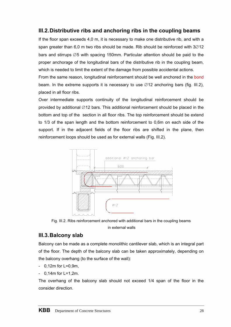
From the same reason, longitudinal reinforcement should be well anchored in the bond
beam. In the extreme supports it is necessary to use ∅12 anchoring bars (fig. III.2),
placed in all floor ribs.
Over intermediate supports continuity of the longitudinal reinforcement should be
provided by additional ∅12 bars. This additional reinforcement should be placed in the
bottom and top of the section in all floor ribs. The top reinforcement should be extend
to 1/3 of the span length and the bottom reinforcement to 0,6m on each side of the
support. If in the adjacent fields of the floor ribs are shifted in the plane, then
reinforcement loops should be used as for external walls (Fig. III.2).
Fig. III.2. Ribs reinforcement anchored with additional bars in the coupling beams
in external walls
III.3. Balcony slab Balcony can be made as a complete monolithic cantilever slab, which is an integral part
of the floor. The depth of the balcony slab can be taken approximately, depending on
the balcony overhang (to the surface of the wall):
- 0,12m for L=0,9m,
- 0,14m for L=1,2m.
The overhang of the balcony slab should not exceed 1/4 span of the floor in the
consider direction.
KBB Department of Concrete Structures 28
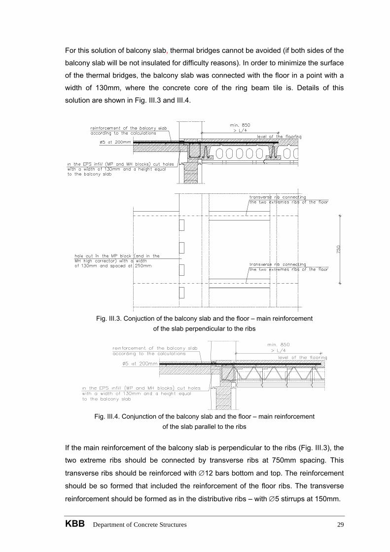
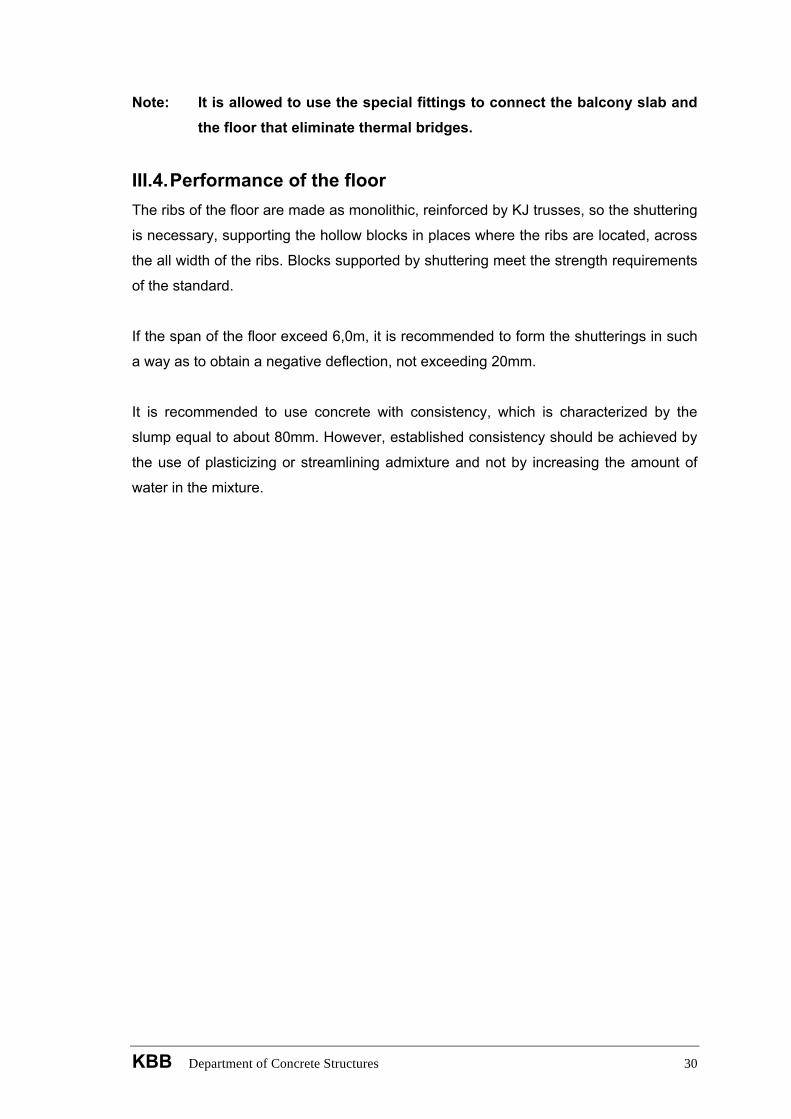
For this solution of balcony slab, thermal bridges cannot be avoided (if both sides of the
balcony slab will be not insulated for difficulty reasons). In order to minimize the surface
of the thermal bridges, the balcony slab was connected with the floor in a point with a
width of 130mm, where the concrete core of the ring beam tile is. Details of this
solution are shown in Fig. III.3 and III.4.
Fig. III.3. Conjuction of the balcony slab and the floor – main reinforcement
of the slab perpendicular to the ribs
Fig. III.4. Conjunction of the balcony slab and the floor – main reinforcement
of the slab parallel to the ribs
If the main reinforcement of the balcony slab is perpendicular to the ribs (Fig. III.3), the
two extreme ribs should be connected by transverse ribs at 750mm spacing. This
transverse ribs should be reinforced with ∅12 bars bottom and top. The reinforcement
should be so formed that included the reinforcement of the floor ribs. The transverse
reinforcement should be formed as in the distributive ribs – with ∅5 stirrups at 150mm.
KBB Department of Concrete Structures 29
Note: It is allowed to use the special fittings to connect the balcony slab and the floor that eliminate thermal bridges.
III.4. Performance of the floor The ribs of the floor are made as monolithic, reinforced by KJ trusses, so the shuttering
is necessary, supporting the hollow blocks in places where the ribs are located, across
the all width of the ribs. Blocks supported by shuttering meet the strength requirements
of the standard.
If the span of the floor exceed 6,0m, it is recommended to form the shutterings in such
a way as to obtain a negative deflection, not exceeding 20mm.
It is recommended to use concrete with consistency, which is characterized by the
slump equal to about 80mm. However, established consistency should be achieved by
the use of plasticizing or streamlining admixture and not by increasing the amount of
water in the mixture.
KBB Department of Concrete Structures 30
KBB Department of Concrete Structures 31
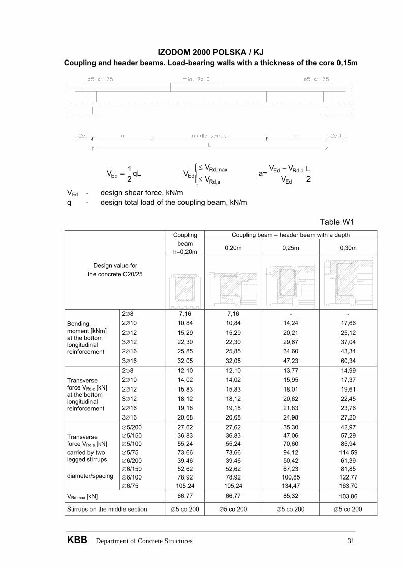
IZODOM 2000 POLSKA / KJ Coupling and header beams. Load-bearing walls with a thickness of the core 0,15m
qL21VEd = =
⎪⎩
⎪⎨⎧
≤
≤
s,Rd
max,RdEd V
VV a
2L
VVV
Ed
c,RdEd −
VEd - design shear force, kN/m q - design total load of the coupling beam, kN/m
Table W1 Coupling beam – header beam with a depth Coupling
beam h=0,20m 0,20m 0,25m 0,30m
Design value for the concrete C20/25
Bending moment [kNm] at the bottom longitudinal reinforcement
2∅8 2∅10 2∅12 3∅12 2∅16 3∅16
7,16 10,84 15,29 22,30 25,85 32,05
7,16 10,84 15,29 22,30 25,85 32,05
- 14,24 20,21 29,67 34,60 47,23
- 17,66 25,12 37,04 43,34 60,34
Transverse force VRd,c [kN] at the bottom longitudinal reinforcement
2∅8 2∅10 2∅12 3∅12 2∅16 3∅16
12,10 14,02 15,83 18,12 19,18 20,68
12,10 14,02 15,83 18,12 19,18 20,68
13,77 15,95 18,01 20,62 21,83 24,98
14,99 17,37 19,61 22,45 23,76 27,20
Transverse force VRd,s [kN] carried by two legged stirrups diameter/spacing
∅5/200 ∅5/150 ∅5/100 ∅5/75 ∅6/200 ∅6/150 ∅6/100 ∅6/75
27,62 36,83 55,24 73,66 39,46 52,62 78,92
105,24
27,62 36,83 55,24 73,66 39,46 52,62 78,92
105,24
35,30 47,06 70,60 94,12 50,42 67,23
100,85 134,47
42,97 57,29 85,94
114,59 61,39 81,85
122,77 163,70
VRd,max [kN] 66,77 66,77 85,32 103,86
Stirrups on the middle section ∅5 co 200 ∅5 co 200 ∅5 co 200 ∅5 co 200
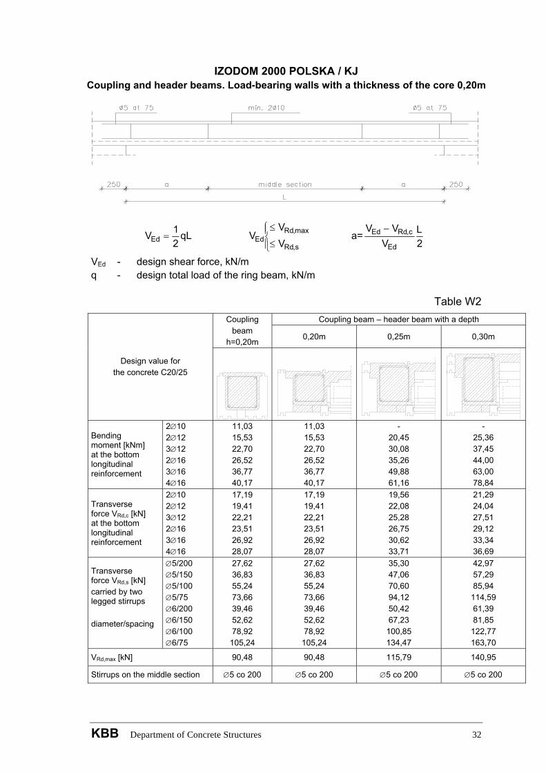
IZODOM 2000 POLSKA / KJ Coupling and header beams. Load-bearing walls with a thickness of the core 0,20m
qL21VEd = =
⎪⎩
⎪⎨⎧
≤
≤
s,Rd
max,RdEd V
VV a
2L
VVV
Ed
c,RdEd −
VEd - design shear force, kN/m q - design total load of the ring beam, kN/m
Table W2 Coupling beam – header beam with a depth Coupling
beam h=0,20m 0,20m 0,25m 0,30m
Design value for the concrete C20/25
Bending moment [kNm] at the bottom longitudinal reinforcement
2∅10 2∅12 3∅12 2∅16 3∅16 4∅16
11,03 15,53 22,70 26,52 36,77 40,17
11,03 15,53 22,70 26,52 36,77 40,17
- 20,45 30,08 35,26 49,88 61,16
- 25,36 37,45 44,00 63,00 78,84
Transverse force VRd,c [kN] at the bottom longitudinal reinforcement
2∅10 2∅12 3∅12 2∅16 3∅16 4∅16
17,19 19,41 22,21 23,51 26,92 28,07
17,19 19,41 22,21 23,51 26,92 28,07
19,56 22,08 25,28 26,75 30,62 33,71
21,29 24,04 27,51 29,12 33,34 36,69
Transverse force VRd,s [kN] carried by two legged stirrups diameter/spacing
∅5/200 ∅5/150 ∅5/100 ∅5/75 ∅6/200 ∅6/150 ∅6/100 ∅6/75
27,62 36,83 55,24 73,66 39,46 52,62 78,92
105,24
27,62 36,83 55,24 73,66 39,46 52,62 78,92
105,24
35,30 47,06 70,60 94,12 50,42 67,23
100,85 134,47
42,97 57,29 85,94
114,59 61,39 81,85
122,77 163,70
VRd,max [kN] 90,48 90,48 115,79 140,95
Stirrups on the middle section ∅5 co 200 ∅5 co 200 ∅5 co 200 ∅5 co 200
KBB Department of Concrete Structures 32