Embed Size (px)
Citation preview

IWPC Mobile RF Filter Groupp
IWPC600 Louis Drive, Suite 104Warminster, PA 18974 USATEL: 215-293-9000 FAX: [email protected], www.iwpc.org

We Are…
• IWPC: technology neutral organization of more than 140 WIRELESS and RF PRODUCT OEM’s and their SUPPLIERS and RF PRODUCT OEM s and their SUPPLIERS.
• Marcus Spectrum Solutions LLC: consulting practice of Dr. Michael Marcus – 25 years in the FCC
• RF Filter Suppliers: Avago Technologies MuRata MuRata TDK-EPC TriQuint Semiconductor
Collectively represent majority market share of RF filtering solutions for mobile devices
22

Meeting Objectives
1. To inform the FCC as to the practical limits of RF filtering technology for mobile devices
2. To understand the FCC's direction for spectrum allocation in the future
3. To encourage the FCC to consider the present limits of RF filtering technology g p g gywhen establishing spectrum rules & regulations
4. To establish contacts which can be cultivated in the future between each member company and the FCC whether can communicate technology improvementscompany and the FCC whether can communicate technology improvements.
IWPC and its members recognize the interrelationship between practical filter performance and spectrum allocations We intend topractical filter performance and spectrum allocations. We intend to update the FCC and the NTIA on a regular basis on the state of the art of commercial filter components and we welcome inquiries on what is practical
3
what is practical.

Topics
IntroductionIntroduction
Background
Real vs. Ideal Filters
Slope, Variation, Temperature, and Bandwidth
Considerations by Band y
Closing Thoughts
4

The “Front End”: Where Acoustic Filters Fit
Power AmplifiersGaAs HBTGaAs FETSi MOSFET
Duplexers, Diplexers, Filtersacoustic (SAW, BAW)dielectric (ceramic, substrate)
CMOS RFIC
Antenna
SwitchesFET (GaAs, SoS)diodemechanical(MEMS)
CMOS RFIC
(MEMS)
Otherpassives, substrate, …
5

Mobile Device Filtering Technologies
Multilayer (LC)Multilayer (LC)
DIELECTRIC
Acoustic
Acoustic:Surface Acoustic Wave
Miniature, Q of 700-800, 10 MHz through 3.5 GHzMiniature, Q of 700 800, 10 MHz through 3.5 GHzOptionally provides balun functionality
Bulk Acoustic WaveMiniature, Q in 1000’s, 500 MHz to 10 GHz
Electric:Electric:Ceramic / Dielectric
Large, Q and frequency supported varies with design and dimensions Lumped / Passives
Large Q in 10’s frequency supported varies with parasitics
6
Large, Q in 10 s, frequency supported varies with parasitics

Real vs. Ideal Filters
Ideal
N l
Real
i ti lNo loss
“Brick Wall” rolloff
insertion loss
Filter slope
Identical
Unmoving with temperature
Filter-to-Filter variation
Motion with temperature
7
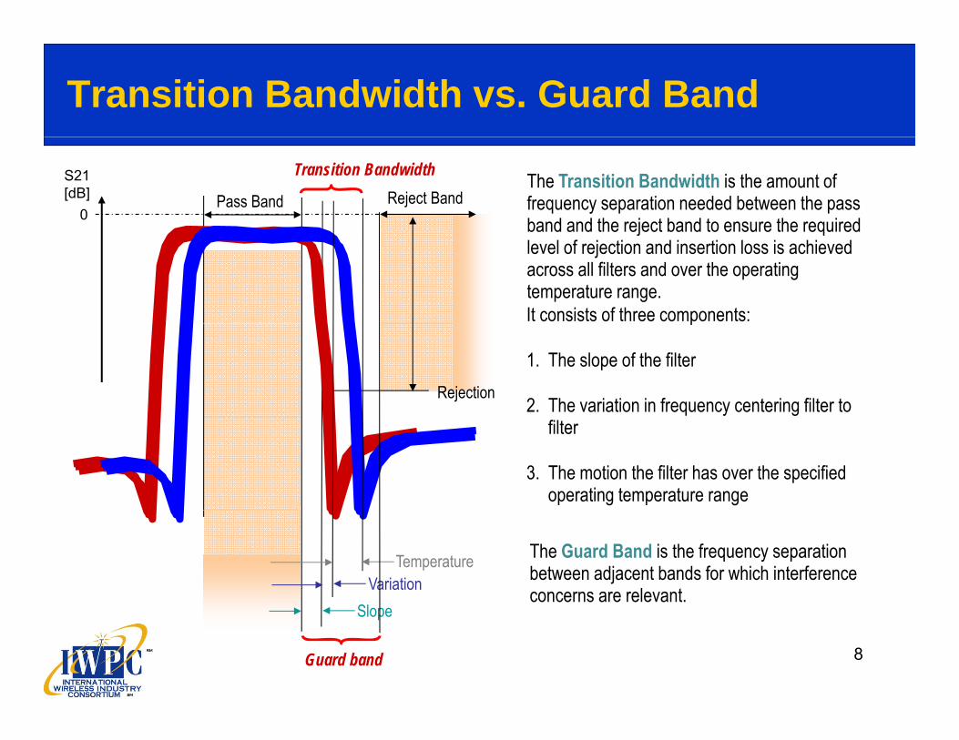
Transition Bandwidth vs. Guard Band
The Transition Bandwidth is the amount of frequency separation needed between the pass band and the reject band to ensure the required
Pass Band Reject BandTransition BandwidthS21
[dB]0 band and the reject band to ensure the required
level of rejection and insertion loss is achieved across all filters and over the operating temperature range.It consists of three components:p
1. The slope of the filter
2. The variation in frequency centering filter to Rejection
filter
3. The motion the filter has over the specified operating temperature range
The Guard Band is the frequency separation between adjacent bands for which interference concerns are relevant.Variation
Temperature
8
Slope
Guard band

Slope
The Slope of the filter is the amount of frequency required to go from pass band edge to minimum rejection. Slope depends on a number of factors, among them:
Q Circle
1. Resonator Q: In general, the higher the Q the steeper the slope.
2. Acoustic Coupling (kT2): In general, the lower the coupling, the
steeper the slope. However adequate acoustic coupling to p p q p gsupport filter band width is required. As a rule of thumb, bandwidth will be no more than kT
2 / 2.
3. Filter design. Filter slope can be enhanced by circuit elements at the cost of out-of-band rejection and / or insertion loss It is also the cost of out of band rejection and / or insertion loss. It is also affected by filter topology.
4. Corner sharpness. For a high Q filter the roll off of the filter is quite fast, and most of the frequency for slope is actually needed to start the roll off The definition of the point to start measuring
freq (1.700GHz to 2.300GHz)
Slope vs. Corner Sharpness
to start the roll off. The definition of the point to start measuring from (how much IL) can have a significant effect on the resulting value for slope.
5. Slope is proportional to frequency.
9

Slope vs. Insertion Loss
For a fixed Rx rejection level (system requirement For a fixed Rx rejection level (system requirement approx. 45dB) the filter slope varies with the maximum insertion loss guaranteed for the highest Tx frequency.
Demand for low insertion loss (efficient use of Demand for low insertion loss (efficient use of battery / long talk time) increases the necessary slope and hence transition band width.
There is a trade-off between transition band and talk ti / itime / user experience.
Similarly, for the Rx filter, there is a trade-off between sensitivity (which influences data rate and network efficiency) and transition bandwidth.
At Right is an example for a PCS BAW duplexer, the right Tx skirt is shown.
10

Insertion Loss vs. Modulation2000 2001 2002 2003 2004 2005 2006 2007 2008 2009 2010 2011 2012 2013
200 kHz
GSM / EDGE200 kHz channel
E-GSM, GSM-850, PCS, DCS
2.4 MHzGSM co band 2 3 5 8
240 kHz to 340kHz
200 kHzUMTS
5 MHz channel
GSM co-band, 2,3,5,8CDMA co-band 2,4,5
LTE co-band, 1,3,6,8,9,11Bands 1,2,4,5,6,8,9
LTE1.4 MHz to
20 MHz channel240 kHz to
340kHz
600 kHz
GSM co-band cell, PCS
1,3,6,7,8,9,11,12,13 …
Cell PCS KPCS JCDMA
200 kHzNarrow CDMA
1.25 MHz channel
Cell, PCS, KPCS, JCDMA
Different modulation types change the portion of the pass band the modulated signal occupies, and hence change how far from the nominal edge of the band the filter insertion loss is actually specified. This “offset” in insertion loss specification point effectively adds to the available guard band.
11
Corner offsets have generally been decreasing with time due to new modulation types and architectural changes like co-banding (using the same filter for multiple modulations, e.g. GSM and UMTS)

Manufacturing Variation
Small variations in the manufacturing process lead to variations in frequency centering from filter to filter.
1. Tuning techniques such as ion milling can be used to “tune” the filters to a relatively narrow range.
2. Since the distribution is “created” rather than natural, it tends to be square rather than Gaussian
3. The variation that can be held is proportional to frequency, and can be though of as a percentage.
4. For low volume applications, variation can be arbitrarily small if one is willing to incur the yield loss. That’s another way of saying you can narrow the variation range somewhat by paying more for the filter if you only need a few of them. For Acoustic Filter at 2 GHz,
0 15 t i ti * 2 109 H5. For high volume applications it may not be practical to artificially narrow the frequency variation as sufficient supply might not be guaranteed.
0.15 percent variation * 2x10⁹ Hz= 3.0 MHz
12

Temperature MotionThe temperature motion of a filter is defined by its temperature
coefficient (Tempco), expressed in parts per million per degree C.
1. Most materials used for filters have a negative temperature coefficient that is the pass band of the filter shifts down in coefficient, that is, the pass band of the filter shifts down in frequency when the filter gets hot, and shifts up in frequency when the filter gets cold.
2. What matters is the excursion of temperature, not the value of the temperature
coldhottemperature.
3. Tempco is a function of material properties.FBAR and BAW has a Tempco of -15 to -30 ppm/CLiTaO3 SAWs have a Tempco of -35 to -42 ppm/C
4 T b lt d b ddi i t t i l t th 4. Tempco can be altered by adding appropriate materials to the resonator composition, usually at the consequence of reducing Qand bandwidth. Any value can theoretically be obtained, including positive temperature coefficients. Temperature compensated ‘TC’-SAWs achieve Tempco of -15 to -30 ppm/C Example for a 2 GHz filter with -30 ppm/C:
5. Temperature motion is proportional to frequency.
6. Motion is slightly higher on the high frequency edge of the filter, due to self heating. Note that for forward duplex (i.e. low freq. Tx) this is a consideration for the Tx filter
-30 ppm/C * [85- (-30) C] * 2x10⁹ Hz= 6.9 MHz
13
this is a consideration for the Tx filter.

BandwidthThe Bandwidth of a filter is defined by the frequency range over which the
insertion loss of the filter is less than the minimum guaranteed insertion loss.
1 F ti filt th b d idth i t fi t d ti l t th
|Bandwidth
Maximum 1. For an acoustic filter, the bandwidth is to a first order proportional to the
acoustic coupling coefficient kT2 of the resonators used to make the
filter.
2. As a rule of thumb, maximum available bandwidth < kT2/2.
3 k 2 i f ti f t i l ti
insertion loss
3. kT2 is a function of material properties.
LiTaO3 SAWs and AlN BAWs (the most common kinds of acoustic filters) have a maximum kT
2 of 7% to 8.4%, limiting bandwidths to below 3.5% to 4.2%
4. LiNbO3 SAWs have higher kT2 – about 12%, so can support wider bO3 S s a e g e T abou %, so ca suppo de
bandwidths. However available Qs are lower, and temperature motion is much higher.
5. Bandwidths can also be stretched by adding external components –basically building an L-C / acoustic resonator hybrid filter. With this technique resonators with k 2 in the 8% range have been used to make technique resonators with kT
2 in the 8% range have been used to make filters with 7.5% bandwidth . However these filters have higher insertion loss and more out-of-band artifacts than conventional filters.
6. The before-mentioned slope vs. insertion loss and insertion loss vs. modulation effects also influence the bandwidth.
Example for a 700 MHz filter with kT
2 = 8%:BW ≈ 8%/2 * 0.7x109 Hz
28 MH
14
≈ 28 MHz

Performance vs. Cost Tradeoffs
ASPSizeBWAtten.I.L.FoPOLES ASPSizeBWAtten.I.L.FoPOLES
As a general rule, when you increase the number of elements associated with a filter design you are doing so to increase the attenuation of the filter. Therefore, the following are true;
Fo = No direct impactI.L. = IncreasesAttenuation = IncreasesAttenuation IncreasesBand Width = No direct impactSize = Increases (same technology based)Price = Increases due to complexity of filter design, material, and
t i ll ti ht ifi ti i t / t ti
15
typically tighter specification requirements / testing.

Performance Improvements over Time
0
-20
[dB
]
-40
Ate
nuat
ion
[
1750 1800 1900 2000 2100
-60
1750 1800 1900 2000 2100
PCS duplexer from 2001
Frequency [MHz]
16

Performance Improvements over Time
0 2
-20
3[dB
]
-40
3
Ate
nuat
ion
[
1750 1800 1900 2000 2100
-60 11
1750 1800 1900 2000 2100
PCS duplexer from 2001 vs. product sold today1. Higher rejection (both Tx and Rx)
Frequency [MHz]
17
1. Higher rejection (both Tx and Rx)2. Lower Insertion loss (including steeper filter skirt and squarer corner)3. Better out-of-band rejection levels4. Smaller size (6x12x2 mm > 2x2.5x0.9 mm)

Bands Aren’t All the Same: Easy Bands
EASY Bands: reasonable duplex gap (≥2%)Moderate pass band (≤3%)
pass band pass band
Band Name Uplink Downlink Duplex Where Comment
AWS-1 1710-1755 2110-2155 FDD US “interesting” – wide gap = hard to match antenna
Moderate pass band (≤3%)No nearby victims or potential jammers
duplex gap
AWS 1 3GPP B4 3GPP2 BC15
1710 1755(2.6%)
2110 2155(2.1%)
FDD(18.4%)
US interesting wide gap hard to match antenna
Cell3GPP B53GPP2 BC0
824-849(3.0%)
869-894(2.8%)
FDD(2.3%)
US / Asia “easy” plan
IMT 3GPP B1 3GPP2 BC6
1920-1980(3.1%)
2110-2170(2.8%)
FDD(6.4%)
World wide except US
“easy” plan
3GPP B6 830-840 (1.2%)
875-885 (1.1%)
FDD(4.1%)
Japan “easy” plan(1.2%) (1.1%) (4.1%)
3GPP B9 1749.9-1784.9(2.0%)
1844.9-1879.9(1.9%)
FDD(3.1%)
Japan “easy” plan
3GPP B10 1710-1770(3.4%)
2110-2170(2.6%)
FDD(17.5%)
S. America “interesting” – wide gap = hard to match antenna
18

Bands Aren’t All the Same: Hard Bands
HARD Bands: frequency plan makes the filtering difficult:Narrow duplex gap (<1 5%)
pass band pass band
Band Name Uplink Downlink Duplex Where Comment
PCS 1850-1910 1930-1990 FDD US “hard” – narrow gap
Narrow duplex gap (<1.5%)and / or Wide pass band (>3.5%)
duplex gap
PCS 3GPP B23GPP2 BC1
1850 1910(3.2%)
1930 1990(3.1%)
FDD(1.04%)
US hard narrow gap
2500 MHz 3GPP B41
2496-2670(6.7%)
2496-2670(6.7%)
TDDn.a.
US “hard” – very wide BW, near WiFi
DCS 1710 1785 1805 1880 FDD Worldwide “hard” narrow gap wide % BWDCS 3GPP B3
1710-1785(4.3%)
1805-1880(4.1%)
FDD(1.11%)
Worldwide except US
hard – narrow gap, wide % BW
EGSM 3GPP B8
880-915(3.9%)
925-960 (3.7%)
FDD(1,09%)
Worldwide except US
“hard” – narrow gap, wide % BW
3GPP B20 832-862( %)
791-821( %)
FDD( %)
Europe “hard” – narrow gap, wide % BW(3.7%) (3.5%) (1.33%)
Note that using wide sections of present TV spectrum for Wireless Services would create new “hard” bands
19
Wireless Services would create new hard bands
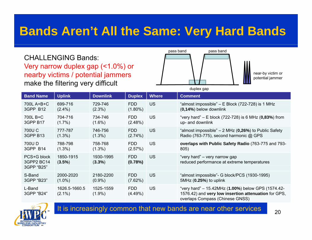
Bands Aren’t All the Same: Very Hard Bands
CHALLENGING Bands: Very narrow duplex gap (<1.0%) ornearby victims / potential jammers near-by victim or
pass band pass band
Band Name Uplink Downlink Duplex Where Comment
700L A+B+C 699-716 729-746 FDD US “almost impossible” – E Block (722-728) is 1 MHz
nearby victims / potential jammers make the filtering very difficult
ypotential jammer
duplex gap
700L A+B+C3GPP B12
699 716(2.4%)
729 746(2.3%)
FDD(1.80%)
US almost impossible E Block (722 728) is 1 MHz (0,14%) below downlink
700L B+C 3GPP B17
704-716(1.7%)
734-746(1.6%)
FDD(2.48%)
US “very hard” – E block (722-728) is 6 MHz (0,83%) from up- and downlink
700U C 3GPP B13
777-787(1 3%)
746-756(1 3%)
FDD(2 74%)
US “almost impossible” – 2 MHz (0,26%) to Public Safety Radio (763 775) second harmonic @ GPS3GPP B13 (1.3%) (1.3%) (2.74%) Radio (763-775), second harmonic @ GPS
700U D 3GPP B14
788-798(1.3%)
758-768(1.3%)
FDD(2.57%)
US overlaps with Public Safety Radio (763-775 and 793-805)
PCS+G block 3GPP2 BC14
G “
1850-1915(3.5%)
1930-1995(3.3%)
FDD(0.78%)
US “very hard” – very narrow gapreduced performance at extreme temperatures
3GPP “B25”
S-Band 3GPP “B23”
2000-2020(1.0%)
2180-2200(0.9%)
FDD(7.62%)
US “almost impossible”- G block/PCS (1930-1995)5MHz (0.25%) to uplink
L-Band 3GPP “B24”
1626.5-1660.5(2.1%)
1525-1559(1.9%)
FDD(4.49%)
US “very hard” – 15.42MHz (1.00%) below GPS (1574.42-1576.42) and very low insertion attenuation for GPS,
20
( ) ( ) ( ) ) yoverlaps Compass (Chinese GNSS)
It is increasingly common that new bands are near other services

Bands Aren’t All the Same: Very Hard Bands
CHALLENGING Bands: Very narrow duplex gap (<1.0%) ornearby victims / potential jammers near-by victim or
pass band pass band
Band Name Uplink Downlink Duplex Where Comment
Sprint 800 817-824 862-869 FDD US
nearby victims / potential jammers make the filtering very difficult
ypotential jammer
duplex gap
Sprint 800 ext. 3GPP BC10
817 824(0.9%)
862 869(0.8%)
FDD4.51%
USonly 1 MHz to re-banded Public Safety Radio
3GPP B7 2500-2570 2620-2690 FDD Worldwide “very hard” – 16.5MHz (0,66%) above WiFi,no guard band to B38
3GPP B38 2570 2620 2570 2620 TDD Europe currently “impossible” no guard band to B7 uplink3GPP B38 2570-2620 2570-2620 TDD Europe, China
currently impossible – no guard band to B7 uplink and downlink
3GPP B40 2300-2400 2300-2400 TDD China, India,E. Europe
currently “impossible” – only 1 MHz guard band from B40 (2300-2400) to WiFi CH1
WiFi 2400-2483.5 2400-2483.5 TDD US /
“very hard “–16.5MHz (0.66%) to B7,O f ( ) CEurope /
AsiaOnly 1 MHz guard band from B40 (2300-2400) to CH1,12.5MHz (0.05%) to B41 (2496-2690)
It is increasingly common that new bands are near other services
21
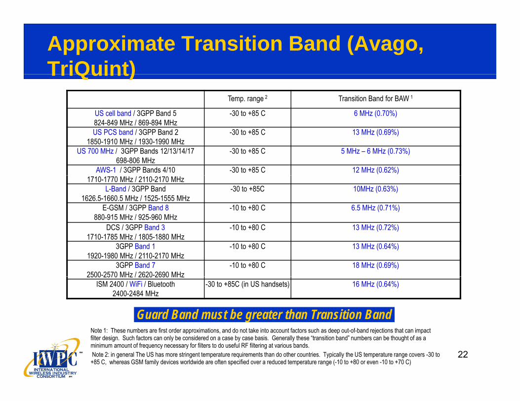
Approximate Transition Band (Avago, TriQuint)TriQuint)
Temp. range 2 Transition Band for BAW 1
US cell band / 3GPP Band 5824-849 MHz / 869-894 MHz
-30 to +85 C 6 MHz (0.70%)824 849 MHz / 869 894 MHzUS PCS band / 3GPP Band 2
1850-1910 MHz / 1930-1990 MHz-30 to +85 C 13 MHz (0.69%)
US 700 MHz / 3GPP Bands 12/13/14/17698-806 MHz
-30 to +85 C 5 MHz – 6 MHz (0.73%)
AWS-1 / 3GPP Bands 4/10 -30 to +85 C 12 MHz (0.62%)1710-1770 MHz / 2110-2170 MHz
L-Band / 3GPP Band 1626.5-1660.5 MHz / 1525-1555 MHz
-30 to +85C 10MHz (0.63%)
E-GSM / 3GPP Band 8880-915 MHz / 925-960 MHz
-10 to +80 C 6.5 MHz (0.71%)
DCS / 3GPP Band 3 10 to +80 C 13 MH (0 72%)DCS / 3GPP Band 31710-1785 MHz / 1805-1880 MHz
-10 to +80 C 13 MHz (0.72%)
3GPP Band 11920-1980 MHz / 2110-2170 MHz
-10 to +80 C 13 MHz (0.64%)
3GPP Band 72500-2570 MHz / 2620-2690 MHz
-10 to +80 C 18 MHz (0.69%)2500 2570 MHz / 2620 2690 MHz
ISM 2400 / WiFi / Bluetooth2400-2484 MHz
-30 to +85C (in US handsets) 16 MHz (0.64%)
Guard Band must be greater than Transition Band
22
Note 1: These numbers are first order approximations, and do not take into account factors such as deep out-of-band rejections that can impact filter design. Such factors can only be considered on a case by case basis. Generally these “transition band” numbers can be thought of as a minimum amount of frequency necessary for filters to do useful RF filtering at various bands.Note 2: in general The US has more stringent temperature requirements than do other countries. Typically the US temperature range covers -30 to +85 C, whereas GSM family devices worldwide are often specified over a reduced temperature range (-10 to +80 or even -10 to +70 C)

Approximate Transition Band (EPC-TDK)
Temp. range Transition Band for SAW / BAW
US cell band / 3GPP Band 5824-849 MHz / 869-894 MHz
-30 to +85 C 10 MHz (1,16%)824 849 MHz / 869 894 MHzUS PCS band / 3GPP Band 2
1850-1910 MHz / 1930-1990 MHz-30 to +85 C 20 MHz (1.04%)
US 700 MHz / 3GPP Bands 12/13/14/17698-806 MHz
-30 to +85 C 8 MHz (1.06%)
AWS-1 / 3GPP Bands 4/10 -30 to +85 C 20 MHz (1,03%)1710-1770 MHz / 2110-2170 MHz
L-Band / 3GPP Band 1626.5-1660.5 MHz / 1525-1555 MHz
-30 to +85C 17 MHz (1.07%)
E-GSM / 3GPP Band 8880-915 MHz / 925-960 MHz
-10 to +80 C 10 MHz (1.09%)
DCS / 3GPP Band 3 10 to +80 C 20 MH (1 11%)DCS / 3GPP Band 31710-1785 MHz / 1805-1880 MHz
-10 to +80 C 20 MHz (1.11%)
3GPP Band 11920-1980 MHz / 2110-2170 MHz
-10 to +80 C 21 MHz (1.03%)
3GPP Band 72500-2570 MHz / 2620-2690 MHz
-10 to +80 C 27 MHz (1.04%)2500 2570 MHz / 2620 2690 MHz
ISM 2400 / WiFi / Bluetooth2400-2484 MHz
-30 to +85C (in US handsets) 27 MHz (1.08%)
Note 1: Required guard band evaluated for CW specification according to LTE requirements (insertion loss < 4dB, attenuation approx. 50dB).
23
Note 2: Evaluation based on proofed filter designs providing sufficient out-of-band rejection levels.Note 3: Temperature range depends on band (US vs. EU/Japan) and customer (for PAiD modules up to +125°C).Note 4: Further design and process improvements needed to meet customer demands for lower insertion attenuation
(longer talk time).

Approximate Transition Band (MuRata)
Temp. range Transition Band for SAW
US cell band / 3GPP Band 5824-849 MHz / 869-894 MHz
-30 to +85 C 13 MHz (1.51%)824 849 MHz / 869 894 MHzUS PCS band / 3GPP Band 2
1850-1910 MHz / 1930-1990 MHz-30 to +85 C 17 MHz (0.89%)
US 700 MHz / 3GPP Bands 12/13/14/17698-806 MHz
-30 to +85 C 10MHz (1.32%)
AWS-1 / 3GPP Bands 4/10 -30 to +85 C 38MHz (2.12%)1710-1770 MHz / 2110-2170 MHz
L-Band / 3GPP Band 1626.5-1660.5 MHz / 1525-1555 MHz
-30 to +85C 17 MHz (1.07%)
E-GSM / 3GPP Band 8880-915 MHz / 925-960 MHz
-10 to +80 C 8.5 MHz (0.93%)
DCS / 3GPP Band 3 10 to +80 C 20 MH (1 11%)DCS / 3GPP Band 31710-1785 MHz / 1805-1880 MHz
-10 to +80 C 20 MHz (1.11%)
3GPP Band 11920-1980 MHz / 2110-2170 MHz
-10 to +80 C 60MHz (2.93%)
3GPP Band 72500-2570 MHz / 2620-2690 MHz
-10 to +80 C 27 MHz (1.04%)2500 2570 MHz / 2620 2690 MHz
ISM 2400 / WiFi / Bluetooth2400-2484 MHz
-30 to +85C (in US handsets) 27 MHz (1.08%)
NOTE: Bands 1 & 2 transition bands are based on Murata standard SAW duplexer specifications. The I.L. characteristics are:
2411/27/2012
The I.L. characteristics are: B1 DPX Tx (1920-1980MHz): 1.6dB max. at 25deg.C B2 DPX Tx (1850.48-1909.52MHz): 3.1dB max. at 25deg.C

Other Solutions
Filtering is not the only solution to potential interferers Filtering: Block the interferer
Other possible solutions include:Other possible solutions include: System Timing: Dodge the interferer
Receiver Linearity: Withstand the interferer Receiver Linearity: Withstand the interferer
Noise Reduction: Don’t create the interferer
Antenna techniques (diversity, MIMO): improve quality & reliability of link
Practical System Solutions may combine these methods.
25