Embed Size (px)
DESCRIPTION
http://www.techprof.nl/images/catalogi/PDF/aandrijftechniek/IWIS_productrange.pdf
Citation preview
Given by:
Member of:
Get in touch with us!Our competent team of employees in the officeand on the road is pleased to offer you extensive advice.
iwis antriebssystemeGmbH & Co. KGAlbert-Roßhaupter-Straße 5381369 München GERMANYTel. +49 89 76909-1600Fax +49 89 76909-1122Internet: www.iwis.comeMail: [email protected]
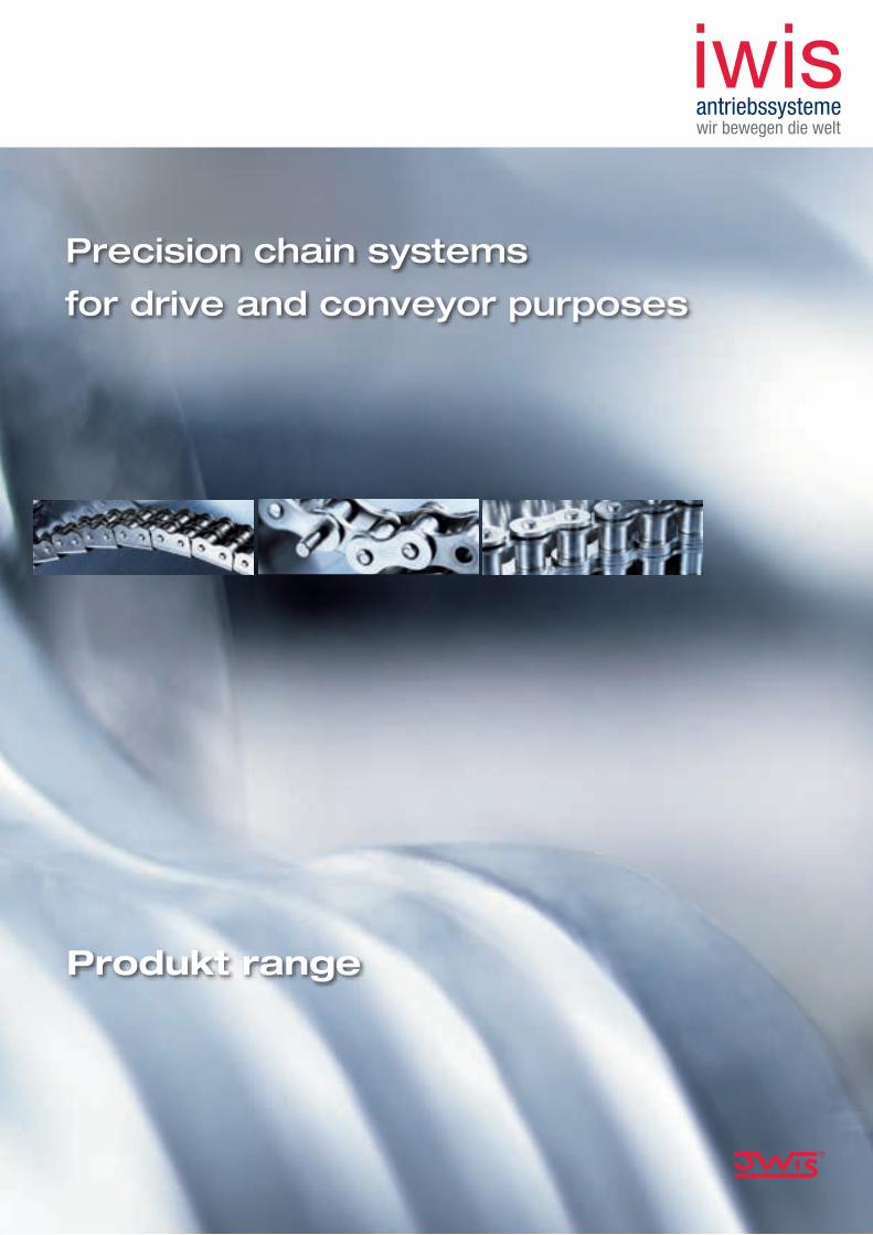
Produkt range
Precision chain systems
for drive and conveyor purposes
For a better orientation in our general catalogue you can use our content-navigator on the back side of the cover. Please turn this page and find the desired page faster.
Pre
cisi
on
chai
n sy
stem
s fo
r d
rive
and
co
nvey
or
pur
po
ses

Content-navigator
Our Company:
Product range:
Drive line products:
Chain guide:
14 Roller chains
20 Conveyor chains
32 MEGAlife chains
42 CR chains
46 Power and free conveyor chains
58 Special chains
70 Sprockets and plate wheels
74 Tools
86 Automatic Tensioners
1 iwis antriebssysteme
100 Perfect lubrication
103 Efficent chain maintenance
104 Chain guideline
106 Questionnaire for chain drives
108 Partners worldwide
Partners worldwide www.iwis.com
SpainPermarin S.A.Poligono Industrial Fuente del JarroC/Ciudad de Sevilla, 1046988 Paterna - ValenciaTel. +34-96-1368000Fax [email protected]
SpainIrati Business S.L.Aptdo.Correos Nr. 2108470 Sant CeloniTel. +34-93-8484048Fax [email protected]
SwitzerlandIWIS AG KettentechnikBahnweg 4 (Postfach 23)5504 OthmarsingenTel. +41-62 8898999Fax +41-62 [email protected]
SwedenBengtssons Maskin A.B.Raseborgsgatan 7 - 9P.O. Box 607216406 Kista (Stockholm)Tel. +46-8-7030270Fax +46-8-7514142info.transmission@bengtssons-maskin.sewww.bengtssons-maskin.se
PolandEnitra sp. zo.o. (GmbH)ul. 1 Maja 6258-300 WalbrzychTel. +48 748439124Fax +48 [email protected]
DenmarkRekord Teknik & Transmission A/SVallensbaekvej 462625 VallensbaekTel. +45-43660999Fax [email protected]
Braziliwis Ketten Correntes do Brasil Ltda.Rua Ella Muhlemann, 200Bairro Ressaca06850.000 Itapecericada Serra -, SPTel. 0055-11-46663927Fax [email protected]
BelgiumS.A. Vermeire Belting N.V.Rue de la Filature, 414800 EnsivalTel. +32-87-322360Fax [email protected]
ArgentinaCasa Mariscal S.A.I.C.Av. Juan B. Alberdi 2371424 Buenos AiresTel. +54-11-49010999Fax [email protected]
AustriaIng. Franz Henzinger GmbHIndustrievertretungIgnaz-Mayer-Str. 44020 LinzTel. +43-732-7745800Fax [email protected]
PortugalJuncor Acessorios Ind. e Agricolas, Lda.Rua Antonio Silva Manrinho, 664100 063 PortoTel. +351-22 619 7360Fax +351 33 619 [email protected]
USASKF USA Inc.1530 Valley Center Parkway Suite 180Bethlehem, PA 18017Tel. +1-610-86148 00Fax +1-610-86148 11Tollfree [email protected]
HungaryBearings Co. Ltd.Gergely u. 3-91105 BudapestTel. +361 2620508Fax +361 [email protected]
TurkeyDinamik Transmisyon ZincirTicaret Ve Sanayii A.S.Kürekciler Sokak No. 48 - 5080000 Karaköy - IstanbulTel. +90-212-2450498Fax +90-212-2435434
Czech RepublicUlmer s.r.o.Generála Vlachého 30574762 Mokré LazceTel. +420-553-757111Fax [email protected]
NorwayIndustri-Fokus A/SPostboks 441 Ökern0513 OsloTel. +47-22-724554Fax [email protected]
ItalyRIMA S.p.A.Via Brunetti 1020156 MilanoTel. +39-02-33404355Fax [email protected]
HollandSpruit Transmissies B.V.Ivoorstraat 41812 RE AlkmaarTel. +31-72-5412000Fax [email protected]
FranceSKF Equipments30-32 Avenue des Trois Peuples78180 Montigny - Le BretonneuxTel. +33-1-30126963Fax +33-1-3026909www.skfequipements.skf.fr
Franceiwis France10, rue du Luxembourg69630 MeyzieuTel. +33-4 78 40 86 68Fax +33-4 78 40 86 [email protected]
FinlandM F G Components OyPajatie 182600 TohmajärviTel. +358-207322020Fax [email protected]
Englandiwis-Flexon Ltd.Unit 8c Bloomfield ParkBloomfield Road, TiptonWest Midlands, DY4 9APTel. +44-1299-400080Fax [email protected]
EURoPE
NoRTH AND SoUTH AmERICA
ASIA
ChinaOn Gear Trading Co., Ltd.5/F CCT Telecom Building11 Wo Shing StreetFotan, Hong KongTel. +852-2690 3320Fax +852-2690 [email protected]
TaiwanChun Chiang Enterprises Co., Ltd.7F, 17, Lane-49, Sec. 1Anho RoadTaipeh 106Tel. +886-2-7818460Fax +886-2-7816078
Chinaiwis Drive System (Shanghai) Co. Ltd.Room #717, German Center88 Keyuan RoadZhangjiang, PudongShanghai 201203 R.O.C.Tel: +86-21-2898 63 88Fax +86-21-2898 63 [email protected]
HollandFlexon BeneluxSlotlaan 5NL-1871 BC SchoorlTel. +31-72-50949-81Fax +31-72-50949-97
AFRICA
EgyptGaicoGeneral Automotive & Ind. Co. Ltd.10,13 Al Farik Mohamed Ibrahim Str.Abbas Al Akkad Region No. 6Zamlek, Nasr City, CairoTel. +2-2-2736265Fax [email protected]
South AfricaBearing Man Ltd.P.O. Box 25191, Gateway 43216 Tetford Circle /Millennium Bridge Business Park4320 La Lucia RidgeTel. +27 31 5766269Fax +27 31 [email protected]
AustraliaCBC Consolidated Bearing CompanyThe Crescent2208 KingsgroveTel. +61 0295021833Fax +61 [email protected]
New ZealandSAECOBearings and Transmission36 Hastie Ave.Mangere, AucklandTel. +64 9 6347540Fax +64 9 [email protected]
AUSTRAlIA
USAFlexon USA, LLCNorth and South America3902 Hanna Circle, Suite FIndianapolis, IN 46241Tel: +1-317-821-3539Fax [email protected]
©Copyright iwis antriebssysteme GmbH & Co. KG, München, Germany 2007
The contents of this catalogue are the copyright of the publisher and may not be reproduced (even extracts) unless permission is granted. Every care has been taken to ensure the accuracy of the information contained in this catalogue but no liability can be accepted for any errors or omissions.
Printed: EN, 03/2007, 3000
1Our Company
Welcome
iwis2
3
1
4

The direct route to your order!
Welcome at
iwis antriebssysteme!
You can reach our Customer Service Team on weekdays from
8 am to 6 pm non-stop.
eMail: [email protected]
Internet: www.iwis.com
Or send your order by fax. For this purpose please use our enquiry
form at the end of this catalogue.
Our Customer Service Team will attend to your enquiries
and orders immediately.
For further information regarding our products please visit also
our company website:
Welcome www.iwis.com
� |
Telefon: +49 89 76909-1600
Fax: +49 89 76909-1122
1

Contents iwis product range
Our Company
1 Welcome
2 Contents
4 iwis antriebssysteme
6 A brand which stands for highest precision
8 People at iwis
10 Highlights, applications and customer benefits
12 Our service offers
14 Roller chains
16 acc.toDIN8187-1
18 acc.toDIN8188-1
18 Double-pitchtype(toDIN8181)
20 Conveyor chains
22 withstraightattachmentplates
24 withbentattachmentplates
29 withextendedbearingpins
30 multiplestrandconnectinglinks
31 withU-shapedattachments
32 MEGAlife maintenance free chains
36 MEGAlifeIrollerchains
37 Conveyorchainswithstraightattachmentplates
38 Conveyorchainswithbentattachmentplates
39 Conveyorchainswithextendedpins
38 MEGAlifeIIrollerchains
Product range1 2
1Our Company Contents
| �

Contents iwis product range
Chain guide
100 Perfect lubrication
103 Efficient chain maintenance
104 Chain guideline
106 Questionnaire for chain drives
108 Partners worldwide
70 Sprockets and plate wheels
74 Tools
86 Automatic Tensioners
Drive line productsProduct range 2 3
4
42 CR chains corrosion resistant chains
46 Power and free conveyor chains
48 Newpowerandfreeconveyorchains
50 Sidebowpowerandfreeconveyorchains
51 Classicpowerandfreeconveyorchains
52 MEGAlifeSFK&SFS
54 Accessories
58 Special chains
60 Platechains
61 Transferchains
63 Gripchains
64 Pallettransportingchains
65 Sidebowchains
66 Antibackbendchains
66 Hollowpinchains
67 Tubetransportchains
67 Cantransportchains
67 Leafchains
Contents www.iwis.com
� |
1

| �
iwis motorsystemeGmbH & Co. KG
iwis antriebssystemeGmbH & Co. KG
FLEXONGmbH
Subsidiary for the automotive sector, for example chain drives and mass balance drives as well
as oil pump drives and gear box chains
Subsidiary for the industrial sector, high precision chains and drive systems for a wide
range of applications
A distribution and service company within the chain
drive industry
München and Strakonice (CZ),as well as Tipton (UK) and
Othmarsingen (CH)
Wilnsdorf and Sontra (D),as well as Tipton (UK) and
Indianapolis (USA)
Company Headquarters, Parent of the independent subsidiary companies,managing organisation of the internationally functioning companies.
1Our Company iwis group
Joh. Winklhofer Beteiligungs GmbH & Co. KG
München and Landsberg (D)as well as Shanghai (CN),
São Paulo (BRA) and Seoul (KR)
� |
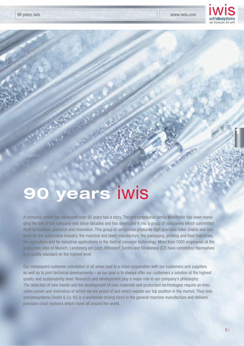
A company which has developed over 90 years has a story. The entrepreneurial family Winklhofer has been mana-ging the fate of the company iwis since decades and has developed it into a group of companies which committed itself to tradition, precision and innovation. This group of companies produces high precision roller chains and sys-tems for the automotive industry, the machine and plant manufacture, the packaging, printing and food industries, the agriculture and for industrial applications in the field of conveyor technology. More than �000 employees at the production sites of Munich, Landsberg am Lech, Wilnsdorf, Sontra and Strakonice (CZ) have committed themselves to a quality standard on the highest level.
Our consequent customer orientation in all areas lead to a close cooperation with our customers and suppliers as well as to joint technical developments – as our goal is to always offer our customers a solution at the highest quality and sustainability level. Research and development play a major role in our company’s philosophy: The detection of new trends and the development of new materials and production technologies require an inno-vative power and motivation of which we are proud of and which explain our top position in the market. Thus iwis antriebssysteme GmbH & Co. KG is a worldwide driving force in the general machine manufacture and delivers precision chain systems which move all around the world.
90 years
90 years iwis www.iwis.com
1

A brand which stands for highest precision.
Technical perfection of highest quality for a maximum customer benefit – that is our high standard. �00% exact replication of more than �0 million spare parts every single day – a quality benchmark which a single expressi-on stands for at iwis: Highest precision. We are proud of that fact and numerous certifications and awards in the quality sector shows us that we follow the right path!
1Our Company A brand which stands for highest precision
| 6

A brand which stands for highest precision www.iwis.com
� |
1

People – The strongest link in our chain.
What moves us:
People. The strongest link
in our chain.
Chains are the reason of our success. However,
the chain is just a product, made from high
quality materials and with innovative production
processes. In order to bring this product to life it
needs people. Our employees are the backbone
of our company and are the deciding factor when
it comes down to success. Their motivation is our
driving force.
Benefiting from our employees’ potential is based
on the understanding that employees stretch to
their maximum capabilities, are given responsibi-
lity and strive to further their creativity.
iwis gives its employees a lot of responsibility
and thus also the duty to achieve the best results
as far as their own performance is concerned.
Recognising the quality of our employees’ work
and their achievements have taken us to where
we are today.
1Our Company People at iwis
| 8

People – The strongest link in our chain.
People at iwis www.iwis.com
9 |
1

Highlights, applications and customer benefits
• Textile machines
• Machine tools
• Machines for processing plastics
• General engineering and systems construction
• Woodworking machinery
• Agricultural machinery
• Office equipment
• Building materials industry
• Construction machinery
• Printing presses
• Paper manufacturing and processing machines
• Copiers
• Ceramics and glass industry
1Our Company Highlights, applications and customer benefits
| �0

• Use of high quality quenched, tempered and case-hardened steels
• High precision fabrication via SPC (statistical process control)
• Quality assurance complying with ISO 9001
• Conveyor technology
• Chemical engineering and process technology
• Tube and can industry
• Packaging machines
• Medical technology
Highlights, applications and customer benefits www.iwis.com
Technical perfection
• Above average length of life
• Excellent wear resistance
• Restricted length tolerances down to 1/6 of the DIN tolerance
Highest possible quality
• Longer maintenance intervals
• Maintenance-friendly, easy and quick to dismantle
• Fewer down times
Benefits to the user
• Optimisation of quality features via special heat treatment
• Constant monitoring of the chains for dimensional accuracy and articulation
• Surface coatings
• Special lubricants
• Special materials (i.e. corrosion-proof)
• Significantly higher fracture- resistance than the norm
• High fatigue strength
• All iwis chains are pretensioned
• Extremely efficient initial lubrication
• Benefits of parallel and synchronous running
• Extremely precise positioning
• Extremely quiet running
• Safety reserves at load peaks
• Reduced stretching during running-in
�� |
1
1

Offering solutions for individual customer problems as well, is our speciality and part of our company’s
philosophy. By conducting feasibility studies hand in hand with our customers, producing components
and executing deformation and stress tests we are able to adjust existing products to individual customer
requirements or to develop new chain drives. By means of vibration and stress tests of the components
the physical properties of the chain are examined. We try the prototypes on test stands which expose the
chain drives to extreme conditions and pressure to ensure its durability and life time. Our customers can
and have to be sure that they receive a high quality product – that is our requirement.
Extreme flexibility
Each customer problem is a challenge for us. Either you need a special conveyor chain or perhaps an own chain
configuration, integrating chain wheels and guides in existing modules:
As a system manufacturer our specialists offer you individual solutions, which go far beyond the chain focus on
the entire application and answer your problem as a whole. Our research and development department stands for
creativity and innovation, as well as for a cooperation hand in hand with our customers. Do not hesitate to contact
us in case you have a special problem.
Troubleshooting
1Our Company Our service offers
| ��

You are important to us and therefore we are happy to support you
in word and deed. Let our competent specialists of our technical
service team and our committed external force advise you. We
would like to do calculations and chain designs for you and give you
advice as far as your choice of the right chain for your applications is
concerned. You can reach our Customer Service Team at any time on
weekdays from 8 am to 6 pm. And by the way: We are happy to ser-
vice you during the operating time of the chain as a reliable partner
in all matters that arise right around the iwis chain.
Service for our customers
The iwis group goes global. By supporting own affiliated companies in Great Britain and Switzerland
as well as sites in Brazil, China, France and the USA the iwis group operates internationally.
iwis products are being sold by distribution partners in more than �0 countries on all continents.
iwis has realised the chances of the globalisation at an early stage and has established a distribution structure
by a targeted positioning which guarantees a worldwide supply. Thus we do not only open up new markets but
our customers can appeal to a familiar and reliable local partner with regard to their business activities abroad.
iwis - your strong partner
outside Germany as well
Our service offers www.iwis.com
�� |
1

2Product Range [email protected] enquiries: +49 89 76909-1122
| ��
Fax-Anfragen unter: +49 89 76909-1122
are characterised by an above-average service life due to excellent wear resistance, high consistency, matchless precision and a considerably higher breaking strength and fatigue strength than required by DIN/ISO standard. All iwis chains are pre-stretched and are provided with a highly efficient initial lubrication.
iwis SL series chains (Super Longlife) have pins with an extremely hard surface. This special design shows outstanding characteristics: Highest wear resistance, a prolonged service life, high breaking and fatigue strength, low susceptibility to deficient operational lubrication, corrosion and frictional corrosion in the chain links.
Roller chains
| ��
Telephone enquiries: +49 89 76909-1600 www.iwis.com
�� |
2
Telefonische Beratung unter: +49 89 76909-1500
�� |
2

2Product Range [email protected] enquiries: +49 89 76909-1122
| �6
�) Also available with straight side plates �) Varying dimensions for cranked links �) Bush chain
Roller chainsaccording to DIN 8187-1, ISO 606: 2004 and iwis standard
Simplex
04 G 42 6 mm 6,00 3.200 3.000 0,07 0,12 2, 3, 7, 8 2,80 4,10 5,00 6,70 7,60 4,00 1,85
05 B-1 G 52 8 mm 8,00 6.000 5.000 0,11 0,18 2, 3, 7, 8 3,16 4,85 7,10 8,10 9,20 5,00 2,31
– G 53 H 1) 3) 8 mm 8,00 9.000 – 0,25 0,34 2, 8 4,76 7,90 7,60 11,70 – 5,00 3,15
– G 62 1/2” 1) 3/8” 9,525 11.000 – 0,22 0,34 2, 3, 7, 8 3,94 6,63 8,20 11,00 12,20 6,35 3,31
06 B-1 G 67 1) * 3/8” 9,525 10.500 9.000 0,28 0,41 2, 3, 6, 7, 8 5,72 8,53 8,20 12,90 14,10 6,35 3,31
– P 83 V 1/2” 12,70 15.500 – 0,29 0,44 2, 3, 6, 7, 8 4,88 7,97 10,20 13,20 14,10 7,75 3,68
– S 84 V 1/2” 12,70 18.000 – 0,38 0,58 2, 3, 6, 7, 8 6,40 9,65 12,00 15,00 16,00 7,75 3,97
08 B-1 L 85 SL* 1/2” 12,70 22.000 18.000 0,50 0,70 2, 3, 6, 7, 8 7,75 11,30 11,80 16,90 18,50 8,51 4,45
10 B-1 M 106 SL* 5/8” 15,875 27.000 22.400 0,67 0,95 2, 3, 6, 7, 8 9,65 13,28 14,40 19,50 20,90 10,16 5,08
12 B-1 M 127 SL* 3/4” 19,05 34.000 29.000 0,89 1,25 2, 3, 4, 6, 7, 8 11,75 15,62 16,40 22,70 23,60 12,07 5,72
16 B-1 M 1611* 1” 25,40 75.000 60.000 2,10 2,70 2, 3, 6, 7, 8 17,02 25,45 21,10 36,10 36,90 15,88 8,28
20 B-1 M 2012 1 1/4” 31,75 120.000 95.000 2,92 3,72 2, 4, 6, 8 19,56 29,01 25,40 40,50 46,30 19,05 10,19
24 B-1 M 2416 1 1/2” 38,10 211.000 160.000 5,50 7,05 2, 4, 6, 8 25,40 37,92 33,50 53,10 60,00 25,40 14,63
28 B-1 M 2819 1 3/4“ 44,45 250.000 200.000 7,35 8,96 2, 4, 6, 8 30,95 46,58 37,00 63,60 69,90 27,94 15,90
32 B-1 M 3219 2” 50,80 315.000 250.000 8,05 10,00 2, 4, 6, 8 30,95 45,57 42,30 65,10 70,10 29,21 17,81
DIN
ISO
no.
Pitc
hp
(”)
Pitc
hp
(mm
)
iwis
(N)a
ve.
Norm
(N
)min.
Bear
inga
rea
f(cm
2 )W
eight
per
mq
(kg/m
)
Chain
com
pone
ntsa
nd
conn
ectin
glin
ks
Nos.
b 1(m
m)m
in.
b 2(m
m)m
ax.
g(m
m)m
ax.
a 1(m
m)m
ax.2
)
a(m
m)m
ax.2
)
Rolle
rd1
(mm
)max
.Pi
nd 2
(mm
)m
ax.
BreakingloadFB Innerlink Outerlink
Ref.
no.iw
is
* easy break – chains with shouldered pins The suffix SL indicates chains with particulary wear-resistant pins.
It should be noted that if cranked links are fitted, the breaking strength of the chain may be reduced by approximately 20%.

Rol
ler
chai
ns
Telephone enquiries: +49 89 76909-1600 www.iwis.com
�� |
2
Roller chainsaccording to DIN 8187-1, ISO 606: 2004 and iwis standard
Duplex
05 B-2 D 52 8” 8,00 9.100 7.800 0,22 0,36 2, 3, 8 3,16 4,85 7,10 13,90 15,00 5,00 2,31 5,64
06 B-2 D 67 1) * 3/8” 9,525 20.000 16.900 0,56 0,78 2, 3, 6, 7, 8 5,72 8,53 8,20 23,40 24,60 6,35 3,31 10,24
08 B-2 D 85 SL* 1/2” 12,70 40.000 32.000 1,00 1,35 2, 3, 6, 7, 8 7,75 11,30 12,20 30,80 32,40 8,51 4,45 13,92
10 B-2 D 106 SL* 5/8” 15,875 56.000 44.500 1,34 1,85 2, 3, 6, 7, 8 9,65 13,28 14,40 36,00 37,50 10,16 5,08 16,59
12 B-2 D 127* 3/4” 19,05 68.000 57.800 1,78 2,50 2, 3, 6, 7, 8 11,75 15,62 16,40 42,10 43,00 12,07 5,72 19,46
16 B-2 D 1611* 1” 25,40 150.000 106.000 4,21 5,40 2, 3, 6, 7, 8 17,02 25,45 21,10 68,00 68,80 15,88 8,28 31,88
20 B-2 D 2012 1 1/4” 31,75 210.000 170.000 5,84 7,36 2, 4, 6, 8 19,56 29,01 25,40 79,70 82,90 19,05 10,19 36,45
24 B-2 D 2416 1 1/2” 38,10 370.000 280.000 11,00 13,85 2, 4, 6, 8 25,40 37,92 33,50 101,80 106,50 25,40 14,63 48,36
28 B-2 D 2819 1 3/4“ 44,45 500.000 360.000 14,70 18,80 2, 4, 6, 8 30,95 46,58 37,00 124,70 129,20 27,94 15,90 59,56
32 B-2 D 3219 2” 50,80 530.000 450.000 16,10 19,80 2, 4, 6, 8 30,95 45,57 42,30 126,00 128,30 29,21 17,81 58,55
Triplex
08 B-3 Tr 85* 1/2” 12,70 58.000 47.500 1,50 2,00 2, 3, 7, 8 7,75 11,30 12,20 44,70 46,30 8,51 4,45 13,92
10 B-3 Tr 106* 5/8” 15,875 80.000 66.700 2,02 2,80 2, 3, 7, 8 9,65 13,28 14,40 52,50 54,00 10,16 5,08 16,59
12 B-3 Tr 127* 3/4” 19,05 100.000 86.700 2,68 3,80 2, 3, 7, 8 11,75 15,62 16,40 61,50 62,50 12,07 5,72 19,46
16 B-3 Tr 1611* 1” 25,40 220.000 160.000 6,32 8,00 2, 3, 6, 7, 8 17,02 25,45 21,10 99,20 100,70 15,88 8,28 31,88
20 B-3 Tr 2012 1 1/4” 31,75 315.000 250.000 8,76 11,00 2, 4, 6, 8 19,56 29,01 25,40 116,10 119,40 19,05 10,19 36,45
24 B-3 Tr 2416 1 1/2” 38,10 560.000 425.000 16,50 20,31 2, 4, 6, 8 25,40 37,92 33,50 150,20 155,40 25,40 14,63 48,36
28 B-3 Tr 2819 1 3/4” 44,45 750.000 530.000 22,05 28,00 2, 4, 6, 8 30,95 46,58 37,00 184,60 188,90 27,94 15,90 59,56
32 B-3 Tr 3219 2” 50,80 795.000 670.000 24,15 29,60 2, 4, 6, 8 30,95 45,57 42,30 184,50 186,50 29,21 17,81 58,55
�) Straight side plate �) Varying dimensions for cranked links
DIN
ISO
no.
Pitc
hp
(“)
Pitc
hp
(mm
)iw
is(N
)ave
.
Norm
(N)m
in.
Bear
inga
rea
f(cm
2 )W
eight
per
mq
(kg/m
)
Chain
com
pone
ntsa
nd
conn
ectin
glin
ks
Nos.
b 1(m
m)m
in.b 2
(mm
)max
.g
(mm
)max
.
a 1(m
m)m
ax.2
)
a(m
m)m
ax.2
)Ro
llerd
1(m
m)m
ax.
Pin
d 2
(mm
)max
.e
(mm
)
BreakingloadFB Innerlink Outerlink
Nr. � Inner links Standard designation B
Nr. � Connecting link with spring clip Standard designation E
Nr. 6 Single cranked link with split pin fastening Standard designation L
Nr. � Double cranked links Standard designation C
Nr. 8 Outer link Standard designation A
Nr. � Connecting link with split pin fasting Standard designation S
ChAin ComponenTS AnD ConneCTing linkS
The suffix SL indicates chains with particulary wear-resistant pins.
It should be noted that if cranked links are fitted, the breaking strength of the chain may be reduced by approximately 20%.
Ref.
no.iw
is

2Product Range [email protected] enquiries: +49 89 76909-1122
| �8
Roller chainsaccording to DIN 8188-1, American standard, ISO 606: 2004
Simplex
08 A-1 L 85 A ANSI 40 1/2” 12,70 18.000 14.100 0,44 0,60 2, 3, 6, 7, 8 7,94 11,15 12,00 16,60 17,50 7,95 3,96 –
10 A-1 M 106 A ANSI 50 5/8” 15,875 29.000 22.200 0,70 1,00 2, 3, 6, 7, 8 9,53 13,84 14,40 20,40 21,70 10,16 5,08 –
12 A-1 M 128 A SL 1) ANSI 60 3/4” 19,05 42.000 31.800 1,06 1,47 2, 3, 4, 6, 7, 8 12,70 17,75 18,00 25,30 26,70 11,91 5,94 –
16 A-1 M 1610 A ANSI 80 1” 25,40 68.000 56.700 1,79 2,57 2, 3, 4, 6, 7, 8 15,88 22,60 22,80 32,10 34,00 15,88 7,92 –
Duplex
08 A-2 D 85 A ANSI 40-2 1/2” 12,70 36.000 28.200 0,88 1,19 2, 3, 4, 6, 7, 8 7,94 11,15 12,00 31,00 31,90 7,95 3,96 14,38
10 A-2 D 106 A ANSI 50-2 5/8” 15,875 56.000 44.400 1,40 1,92 2, 3, 6, 7, 8 9,53 13,84 14,40 38,60 39,90 10,16 5,08 18,11
12 A-2 D 128 A 1) ANSI 60-2 3/4” 19,05 84.000 63.600 2,12 2,90 2, 3, 4, 6, 7, 8 12,70 17,75 18,00 48,10 49,50 11,91 5,94 22,78
16 A-2 D 1610 A ANSI 80-2 1” 25,40 145.000 113.400 3,58 5,01 2, 3, 4, 6, 7, 8 15,88 22,60 22,80 61,40 63,30 15,88 7,92 29,29
Triplex
08 A-3 Tr 85 A ANSI 40-3 1/2” 12,70 50.000 42.300 1,32 1,78 2, 3, 6, 7, 8 7,94 11,15 12,00 45,40 46,30 7,95 3,96 14,38
10 A-3 Tr 106 A ANSI 50-3 5/8” 15,875 80.000 66.600 2,10 2,89 2, 3, 6, 7, 8 9,53 13,84 14,40 56,70 58,00 10,16 5,08 18,11
12 A-3 Tr 128 A ANSI 60-3 3/4” 19,05 125.000 95.400 3,18 4,28 2, 3, 4, 6, 7, 8 12,70 17,75 18,00 71,00 72,30 11,91 5,94 22,78
16 A-3 Tr 1610 A ANSI 80-3 1” 25,40 210.000 170.100 5,37 7,47 2, 3, 4, 6, 7, 8 15,88 22,60 22,80 90,70 92,70 15,88 7,92 29,29
Roller chains, double-pitch typeaccording to DIN 8181 and ISO 1275:1995
208 B LR 165 SL - 1” 25,40 22.000 18.000 0,50 0,52 2, 4, 6, 8 7,75 11,30 11,80 16,90 18,60 8,51 4,45 –
210 B LR 206 SL - 1 1/4” 31,75 28.000 22.400 0,67 0,63 2, 4, 6, 8 9,65 13,28 15,10 19,50 20,80 10,16 5,08 –
212 B LR 247 SL - 1 1/2” 38,10 34.000 29.000 0,89 0,85 2, 4, 6, 8 11,75 15,62 16,10 22,70 24,10 12,07 5,72 –
216 B LR 3211 - 2” 50,80 75.000 60.000 2,10 2,10 2, 4, 6, 8 17,02 25,45 20,60 36,10 38,10 15,88 8,28 –
�) Also available with straight side plates �) Varying dimensions for cranked links
ANSI
Ref.
no.
Pitc
hp
(mm
)iw
is(N
)ave
.
Norm
(N)m
in.Be
aring
are
af(
cm2 )
Weig
htp
erm
q(kg
/m)
Chain
com
pone
ntsa
nd
conn
ectin
glin
ks
Nos.
b 1(m
m)m
in.b 2
(mm
)max
.g
(mm
)max
.a 1
(mm
)max
.2)
a(m
m)m
ax.2
)Ro
ller
d 1(m
m)m
ax.
Pin d 2(m
m)m
ax.
BreakingloadFB Innerlink Outerlink
e(m
m)
Roller Chains, double-pitch type
It should be noted that if cranked links are fitted, the breaking strength of the chain may be reduced by approximately 20%.
The suffix SL indicates chains with particulary wear-resistant pins.
DIN
ISO
no.
Ref.
no.iw
is
Pitc
hp
(”)

Rol
ler
chai
ns
Telephone enquiries: +49 89 76909-1600 www.iwis.com
�9 |
2
High performance chainsQuality products with a world reputation
• Use of high-grade heat-treatable steels which are made exclusively for iwis to their material analysis, tolerance and surface quality.
• Each chain part is manufactured a million times daily to the same precision. This production is monitored by SPC (statistical process control).
• All chain parts are heat-treated, using spe-cial processes to optimize quality features.
high quAliTy iS BASeD on eACh inDiviDuAl pArT Being TeChniCAlly perFeCT
• Constant geometry and high surface qua-lity result from the use of modern produc-tion technologies.
• Chains are checked for dimensional accu-racy: length tolerance, freedom of articu-lation and assembly component integrity, inspection of the press-in seating of the pin outer links and bush-inner link inter-faces.
• The high standard of quality assurance conforms with the high requirements of ISO 9001: 2006.
• For special applications - Surface coatings - Special lubrications - Reduced length toleranced chains - Special materials
(e.g. corrosion resistant)
iwis shouldered pin (DIN 8187). SL serie chains have pins with still higher resistance to wear.
iwis bush – manufactured as a special, surface treated, seamless closed cylinder.
iwis roller – an absolutely cylindrical form guarantees ideal sliding-contact bearing properties.
iwis side plate – optimally dimensioned, shaped with precision, and heat-treated for toughness and hardness.

�� |
Telephone enquiries: +49 89 76909-1600 www.iwis.com
2
iwis conveyor chains can especially be matched with the demands of customer applications. iwis does not only supply the customer with a wide range of special straight attachments and bent attachment plates, but the Technical Service Team offers solutions for individual customer demands and designs custom-made products.
iwis conveyor chains offer the user the benefits of parallel and synchronous running, extre-mely precise positioning, quiet running and a significantly higher breaking resistance than the norm. Also available: conveyor chains with extended bearing pins, conveyor chains with U-shaped attachments and multiple strand connecting links.
Conveyor chains
�� |
2

2Product range [email protected] enquiries: +49 89 76909-1122
| ��
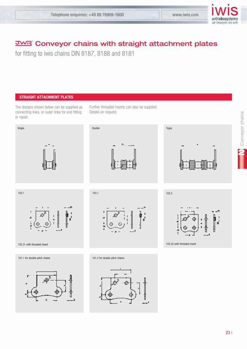
Conveyor chains with straight attachment platesfor fitting to iwis chains DIN 8187, 8188 and 8181
plate no. 102.1
- P 83 V 1/2” 12,7 13,0 19,0 4,2 8,1 – – 4,5 – 18,0 1,5 – –
- S 84 V 1/2” 12,7 13,0 19,0 4,2 9,8 – – 4,5 – 18,0 1,5 – –
08 B-1 L 85 SL 1) 1/2” 12,7 13,0 19,0 4,2 11,6 25,5 39,4 5,4 – 18,0 1,5 4 5,2
10 B-1 M 106 SL 1) 5/8” 15,875 16,3 24,3 5,2 13,6 30,1 46,6 6,8 – 24,0 1,6 5 5,3
12 B-1 M 127 SL 1) 3/4” 19,05 19,1 29,1 6,2 15,9 35,3 54,7 7,4 – 28,0 1,8 5 5,5
16 B-1 M 1611 1) 1” 25,4 24,6 36,6 8,2 25,9 57,8 89,7 10,4 – 36,2 3,0 6 8,2
08 A-1 ANSI 40 L 85 A 1) 1/2” 12,7 13,0 19,0 4,2 11,4 25,8 40,2 4,5 – 18,0 1,5 – –
10 A-1 ANSI 50 M 106 A 1) 5/8” 15,875 16,3 24,3 5,2 14,1 32,3 50,4 6,8 – 24,0 1,6 – –
12 A-1 ANSI 60 M 128 A SL 1) 3/4” 19,05 19,1 29,1 6,2 18,1 40,8 63,6 7,4 – 28,0 2,4 – –
16 A-1 ANSI 80 M 1610 A 1) 1” 25,4 24,6 36,6 8,2 23,0 52,2 81,5 10,4 – 36,2 3,0 – –
plate no. 103.1 and 103.2
- P 83 V 2) 1/2” 12,7 17,0 23,0 4,2 8,1 – – 4,5 12,7 23,6 1,5 – –
- S 84 V 1/2” 12,7 17,0 23,0 4,2 9,8 – – 4,5 12,7 23,6 1,5 – –
08 B-1 L 85 SL 1) 1/2” 12,7 17,0 23,0 4,2 11,6 25,5 39,4 5,4 12,7 23,6 1,5 4 5,2
10 B-1 M 106 SL 1) 5/8” 15,875 16,3 25,8 5,2 13,6 30,1 46,6 7,5 15,8 31,0 1,6 5 5,3
12 B-1 M 127 SL 1) 3/4” 19,05 18,3 29,0 6,2 15,9 35,3 54,7 9,0 19,0 37,2 1,8 5 5,5
16 B-1 M 1611 1) 1” 25,4 28,45 41,55 8,2 25,9 57,8 89,7 10,35 25,4 47,2 3,0 6 8,2
08 A-1 ANSI 40 L 85 A 1) 1/2” 12,7 17,0 23,0 4,2 11,4 25,8 40,2 4,5 12,7 23,6 1,5 – –
10 A-1 ANSI 50 M 106 A 1) 5/8” 15,875 16,3 25,8 5,2 14,1 32,3 50,4 7,5 15,8 31,0 1,6 – –
12 A-1 ANSI 60 M 128 A SL 1) 3/4” 19,05 18,3 29,0 6,2 18,1 40,8 63,6 9,0 19,0 37,2 2,4 – –
16 A-1 ANSI 80 M 1610 A 1) 1” 25,4 28,45 41,55 8,2 23,0 52,2 81,5 10,35 25,4 47,2 3,0 – –
plate no. 101.1 and 101.2
208 B LR 165 SL 1” 25,4 14,3 20,5 4,2 11,6 – – 6,5 14,0 24,2 1,5 – –
210 B LR 206 SL 1 1/4” 31,75 16,3 25,8 5,2 13,8 – – 7,5 18,0 30,2 1,6 – –
212 B LR 247 S 1 1/2” 38,1 19,2 29,5 6,2 15,9 – – 9,0 20,0 36,2 1,7 – –
216 B LR 3211 2” 50,8 28,5 40,6 8,2 25,9 – – 10,2 28,0 48,2 3,0 – –
�) Available for both double and triple strand chains �) Nominal pitch
Ref.
no.iw
is
p(”)
p(m
m)
a(m
m)
b(m
m)
d(m
m)
Sing
lestr
and
chain
s
e 1(m
m)
Doub
lestr
and
chain
s
e 2(m
m)
Tripl
estr
and
chain
s
e 3(m
m)
g(m
m)
i(mm
)
l(mm
)
s(m
m)
M(m
m)
m.m
ax(m
m)
Pitch2) Threadedinsert
DIN
ISO
no.
Con
veyo
rch
ains
�� |
Telephone enquiries: +49 89 76909-1600 www.iwis.com
2
TripleDoubleSingle
�0�.�
�0�.�� with threaded insert
�0�.� �0�.�
�0�.�� with threaded insert
�0�.� for double-pitch chains �0�.� for double-pitch chains
Conveyor chains with straight attachment platesfor fitting to iwis chains DIN 8187, 8188 and 8181
STrAighT ATTAChmenT plATeS
The designs shown below can be supplied as connecting links, or outer links for end fitting or repair.
Further threaded inserts can also be supplied. Details on request.

2Product range [email protected] enquiries: +49 89 76909-1122
| ��
Conveyor chains with bent attachment platesfor fitting to iwis chains DIN 8187, 8188 and 8181
Form 202.1
- P 83 V 1/2“ 12,7 8,0 4,2 24,1 36,1 – – – – 4,5 14,0 – 18,1 1,5 – –
- S 84 V 1/2“ 12,7 8,0 4,2 25,8 37,8 – – – – 4,5 14,0 – 18,1 1,5 – –
08 B-1 L 85 SL 1) 1/2“ 12,7 8,0 4,2 27,6 39,6 41,5 53,5 55,4 67,4 5,4 14,0 – 18,1 1,5 4 5,2
10 B-1 M 106 SL 1) 5/8“ 15,875 9,0 5,2 33,6 49,6 50,1 66,1 66,6 82,6 6,8 18,0 – 24,0 1,6 5 5,3
12 B-1 M 127 SL 1) 3/4“ 19,05 10,0 6,2 41,1 61,1 60,5 80,5 79,9 99,9 7,4 22,6 – 28,0 1,8 5 5,5
16 B-1 M 1611 1) 2) 1“ 25,4 16,0 8,2 53,9 77,9 85,8 109,8 117,7 141,7 10,4 26,0 – 36,2 3,0 6 8,2
08 A-1 ANSI 40 L 85 A 1) 1/2“ 12,7 8,0 4,2 27,4 39,4 41,8 53,8 56,2 68,2 4,5 14,0 – 18,1 1,5 – –
10 A-1 ANSI 50 M 106 A 1) 5/8“ 15,875 9,0 5,2 34,1 50,1 52,3 68,3 70,4 86,4 6,8 18,0 – 24,0 1,6 – –
12 A-1 ANSI 60 M 128 A SL 1) 3/4“ 19,05 13,0 6,2 38,9 58,9 61,6 81,6 84,4 104,4 7,4 20,4 – 28,0 2,4 – –
16 A-1 ANSI 80 M 1610 A 1) 2) 1“ 25,4 16,0 8,2 51,0 75,0 80,2 104,2 109,5 133,5 10,4 26,0 – 36,2 3,0 – –
Form 203.1 und 203.2
- P 83 V 2) 1/2“ 12,7 9,5 4,2 29,1 41,1 – – – – 4,5 16,5 12,7 23,6 1,5 – –
- S 84 V 2) 1/2“ 12,7 9,5 4,2 30,8 42,8 – – – – 4,5 16,5 12,7 23,6 1,5 – –
08 B-1 L 85 SL 1) 2) 1/2“ 12,7 9,5 4,2 32,6 44,6 46,5 58,5 60,4 72,4 5,4 16,5 12,7 23,6 1,5 4 5,2
10 B-1 M 106 SL 1) 2) 5/8“ 15,875 11,0 5,2 30,6 49,6 47,1 66,1 63,6 82,6 7,5 18,0 15,8 31,0 1,6 5 5,3
12 B-1 M 127 SL 1) 2) 3/4“ 19,05 12,0 6,2 35,5 56,9 54,9 76,3 74,3 95,7 9,0 20,5 19,0 37,2 1,8 5 5,5
16 B-1 M 1611 1) 2) 1“ 25,4 18,0 8,2 57,7 83,9 89,6 115,8 121,5 147,8 10,4 29,0 25,4 47,2 3,0 6 8,2
08 A-1 ANSI 40 L 85 A 1) 2) 1/2“ 12,7 9,5 4,2 32,4 44,4 46,8 58,8 61,2 73,2 4,5 16,5 12,7 23,6 1,5 – –
10 A-1 ANSI 50 M 106 A 1) 2) 5/8“ 15,875 11,0 5,2 31,1 50,1 49,3 68,3 67,3 86,4 7,5 18,0 15,8 31,0 1,6 – –
12 A-1 ANSI 60 M 128 A SL 1) 2) 3/4“ 19,05 13,0 6,2 37,3 58,7 60,0 81,4 82,8 104,2 9,0 20,3 19,0 37,2 2,4 – –
16 A-1 ANSI 80 M 1610 A 1) 2) 1“ 25,4 18,0 8,2 54,8 81,0 84,0 110,2 113,3 139,5 10,4 29,0 25,4 47,2 3,0 – –
Form 201.1 und 201.2
208 B LR 165 SL 2) 1“ 25,4 10,0 4,2 26,2 38,6 – – – – 6,5 13,5 14,0 24,2 1,5 – –
210 B LR 206 SL 2) 1 1/4“ 31,75 11,0 5,2 30,6 49,6 – – – – 7,5 18,0 18,0 30,2 1,6 – –
212 B LR 247 SL 2) 1 1/2“ 38,1 13,0 6,2 34,9 55,5 – – – – 9,0 19,8 20,0 36,2 1,7 – –
216 B LR 3211 2) 2“ 50,8 18,0 8,2 57,7 81,9 – – – – 10,2 28,0 28,0 48,2 3,0 – –
�) Available also for corresponding double and triple strand chains �) The bent attachment plates can also be fitted facing inwards with the top part
p(Z
oll)
Pitch
p(m
m)
c(m
m)
d(m
m)
e 1(m
m)
f 1(m
m)
e 2(m
m)
f 2(m
m)
e 3(m
m)
f 3(m
m)
g(m
m)
h(m
m)
i(mm
)
l(mm
)
s(m
m)
M(m
m)
mm
ax.
(mm
)
Singlechains Doublechains Triplechains Threadedinsert
Ref.
no.iw
is
DIN
ISO
no.

Con
veyo
rch
ains
�� |
Telephone enquiries: +49 89 76909-1600 www.iwis.com
2
Single Double Triple
�0�.�� with threaded insert
�0�.�
�0�.� for double-pitch chains �0�.� for double-pitch chains
�0�.�
�0�.�� with threaded insert
�0�.�
�0�.�� with threaded insert
BenT ATTAChmenT plATeS
The designs shown below can be supplied as connecting links, or outer links for end fitting or repair. When the attachment is fitted facing
inwards over the chain, threaded inserts cannot be used. Further threaded inserts can also be supplied. Details on request.
Conveyor chains with bent attachment platesfor fitting to iwis chains DIN 8187, 8188 and 8181
2Product range [email protected] enquiries: +49 89 76909-1122
| �6
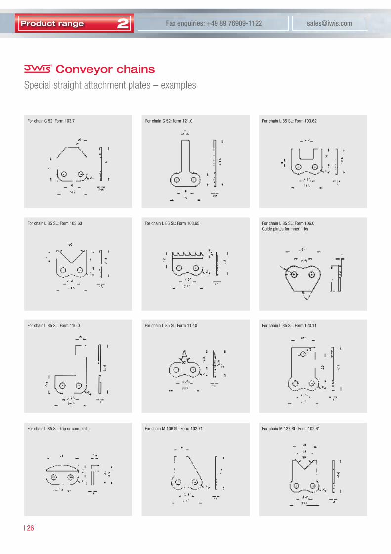
Conveyor chainsSpecial straight attachment plates – examples
For chain G ��: Form �0�.� For chain G ��: Form ���.0 For chain L 8� SL: Form �0�.6�
For chain L 8� SL: Form �0�.6� For chain L 8� SL: Form �0�.6� For chain L 8� SL: Form �06.0Guide plates for inner links
For chain L 8� SL: Form ��0.0 For chain L 8� SL: Form ���.0 For chain L 8� SL: Form ��0.��
For chain L 8� SL: Trip or cam plate For chain M �06 SL: Form �0�.�� For chain M ��� SL: Form �0�.6�

Con
veyo
rch
ains
�� |
Telephone enquiries: +49 89 76909-1600 www.iwis.com
2
For chain M ��� SL: Form ���.�� For chain M ��8 A SL: Form �0�.6� For chain M ��8 A SL: Form ��9.�
For chain M ��� SL: Form �0�.6� For chain L 8� SL: Form �0�.�� For chain M ��� A SL: Form �0�.6�
For chain M ��8 A SL: Form �0�.6� For chain L 8� SL: Form �0�.6� For chain L 8� SL: Form ���.0
For chain L 8� SL: Form ���.� For chain L 8� SL: Form ���.09 For chain L 8� SL: Form ���.0
Conveyor chainsSpecial straight attachment plates – examples

2Product range [email protected] enquiries: +49 89 76909-1122
| �8
Conveyor chainsSpecial bent attachment plates – examples
Similar attachment plate designs for other chain types are available on request, as are other attachment plate designs. For some special attachment plates minimum order quantities are required.
For chain L 8� SL: Form �0�.8 For chain L 8� SL: Form ��0.�� For chain M �06 SL: Form ��0.��
For chain M �06 SL: Form �0�.6 For chain M ��� SL: Form �0�.8 For chains M ��8 A SL/M ��8 A SB, Form ���.�
For chain M ��8 A SL: Form �0�.� For chain M ��8 A SL: Form �0�.8 For chains M �6�0 A und M �6�� SL: Form �0�.��
For chain M ��� SL: Form �0�.�� For chain M �06 SL: Form �0�.�� For chain L 8� SL: Form �0�.��

Con
veyo
rch
ains
�9 |
Telephone enquiries: +49 89 76909-1600 www.iwis.com
2
Conveyor chains extended bearing pinsfor fitting to iwis chains DIN 8187, 8188 and 8181
pin design A, B, C
05 B-1 G 52 – 8,0 3,16 5,0 2,31 17,5 10,0 27,5 20,0 10,5
06 B-1 G 67 3/8” 9,525 5,72 6,35 3,31 22,0 10,0 34,0 22,0 11,5
- P 83 V 1/2” 12,7 4,88 7,75 3,68 22,0 10,0 37,0 25,0 13,0
08 B-1 L 85 SL 1/2” 12,7 7,75 8,51 4,45 25,5 10,0 40,5 25,0 13,0
10 B-1 M 106 SL 5/8” 15,875 9,65 10,16 5,08 30,0 12,0 48,0 30,0 15,5
12 B-1 M 127 SL 3/4” 19,05 11,75 12,07 5,72 36,0 15,0 51,0 30,0 15,5
16 B-1 M 1611 1” 25,4 17,02 15,88 8,28 53,5 20,0 68,5 35,0 18,0
08 A-1 ANSI 40 L 85 A 1/2” 12,7 7,94 7,95 3,96 25,5 10,0 45,3 30,0 15,5
10 A-1 ANSI 50 M 106 A 5/8” 15,875 9,53 10,16 5,08 31,5 12,0 48,0 29,0 15,0
12 A-1 ANSI 60 M 128 A SL 3/4” 19,05 12,70 11,91 5,94 38,0 14,0 48,0 24,0 12,5
16 A-1 ANSI 80 M 1610 A 1” 25,4 15,88 15,88 7,92 49,5 19,0 61,3 31,0 16,0
208 B LR 165 SL 1” 25,4 7,75 8,51 4,45 25,5 10,0 40,5 25,0 13,0
210 B LR 206 SL 1 1/4” 31,75 9,65 10,16 5,08 30,0 12,0 48,0 30,0 15,5
212 B LR 247 SL 1 1/2” 38,1 11,75 12,07 5,72 36,0 15,0 51,0 30,0 15,5
216 B LR 3211 2” 50,8 17,02 15,88 8,28 53,5 20,0 68,5 35,0 18,0
�) For multiple strand chains on request. Other pin designs and lengths available on request.
A B C
Ref.
no.iw
is1)
p(”)
exTenDeD BeAring pinS
The designs shown below can be supplied as connecting links or outer links for end fitting or repair (C only as outer link).
p(m
m)
Pitch
inner
widt
hb 1
(mm
)
Rolle
rdiam
eter
d 1(m
m)
Exte
nded
bea
ring
pind
iamet
erd 2
(mm
)
L 1(m
m)
I 1(m
m)
L 2(m
m)
I 2(m
m)
I 3(m
m)
DesignApinlength DesignBandCpinlength
DIN
ISO
no.

2Product range [email protected] enquiries: +49 89 76909-1122
| �0
Multiple strand connecting linksfor attachment of components 1)
Double
05B-1 G 52 8 mm 7,94 3,16 5,0 2,31 14,9 – 4,0 –
06B-1 G 67 3/8 9,42 5,72 6,35 3,31 24,5 34,6 7,0 17,5
Double / Triple
08B-1 L 85 SL 1/2 12,58 7,75 8,51 4,45 32,3 46,2 11,3 25,2
10B-1 M 106 SL 5/8 15,76 9,65 10,16 5,08 37,4 53,9 13,3 29,9
12B-1 M 127 SL 3/4 18,95 11,75 12,07 5,72 42,9 62,4 15,6 35,1
16B-1 M 1611 1 25,3 17,02 15,88 8,28 68,7 100,6 25,5 57,4
08 A-1 ANSI 40 L 85 A 1/2 12,58 7,94 7,95 3,96 31,8 46,2 11,2 25,5
10 A-1 ANSI 50 M 106 A 5/8 15,76 9,53 10,16 5,08 39,8 57,9 13,8 32,0
12 A-1 ANSI 60 M 128 A SL 3/4 18,95 12,70 11,91 5,94 49,4 72,2 17,8 40,6
16 A-1 ANSI 80 M 1610 A 1 25,3 15,88 15,88 7,92 63,2 92,6 22,6 51,9
Multiple strand connecting links permit com-ponents to be fitted easily at specific locations on the chain.
�) Please note the exact pitch measure „p“ for the assembly of special components.
Mounted part
Single strand chain with double strand connecting link Single strand chain with double strand connecting link Single strand chain with triple strand connecting link
Mounted part Mounted part
exAmpleS
Chain
p(”
)
Multiple strand connecting links can be sup-plied with normal side plates or as connecting links with straight or bent attachment plates, mounted on one or both sides.
Note: The pitch of holes in the mounted part (component) differ from chain pitch.
PitchPi
tch
ofh
olesi
n
com
pone
nt(m
m)
Inside
widt
hb 1
(mm
)
Rolle
rdiam
eter
d 1(m
m)
Pin
diam
eter
d 2(m
m)
a 2(m
m)
a 3(m
m)
A 2(m
ax.m
m)
A 3(m
ax.m
m)
Outsidewidth Blockwidth
Ref.
no.iw
is
DIN
ISO
no.

Con
veyo
rch
ains
�� |
Telephone enquiries: +49 89 76909-1600 www.iwis.com
2
Conveyor chains with U-shaped attachmentsfor fitting to iwis roller chains DIN 8187 and 8188
u-shaped attachment 303.2 / 303.32 / 303.9
08B-1 L 85 SL 12,7 17,8 19,8 21,5 9,5 4,1 6,3 14,6 12,6 3,0 24,2 1,5 4 5,2
08B-2 D 85 SL 12,7 31,8 33,9 35,5 9,5 4,1 6,3 28,5 13,9 3,0 24,2 1,5 4 5,2
10B-1 M 106 SL 15,875 20,0 22,0 24,0 12,0 7,1 7,5 16,6 15,8 3,0 31,0 1,5 5 5,2
16 A-1 ANSI 80 M 1610 A 25,4 33,7 36,5 38,4 16,2 8,7 10,5 27,3 25,3 5,0 49,2 2,1 6 7,3
�) Alternative diameters: for L 8� SL: �,8 mm / for M �06 L: �,� mm
Chain width:When U-shaped attachments are fitted between the inner and outer plates, the chain width increases above the norm.a = pin length of connecting link
�”-double strand chain with special U-shaped attachment. Base chain: iwis M �6�0 A
No. �0�.9� for chain D 8� SL No. �0�.9� for chain L 8� SL
With D 8� SL threaded inserts are positioned transversely to the chain
Cover material: PerbunanHardness: 6� Shore / Temperature: -�0 up to +�00
Form �0�.� with standard attachment holes Form �0�.�� with threaded inserts Form �0�.9 with rubber cover
SpeCiAl DeSignS
p(m
m)
Pitch
A(m
m)
B(m
m)
a(m
m)
c(m
m)
d1(m
m)
g(m
m)
h(m
m)
i(mm
)
k(m
m)
l(mm
)
s(m
m)
M(m
m)
mm
ax.
(mm
)
Threadedinsert
Ref.
no.iw
is
DIN
ISO
no.

2Product range [email protected] enquiries: +49 89 76909-1122
| ��
MEGAlife maintenance free roller and conveyor chains can be applied in all areas where post installation lubrication is not at all or only partly possible. This is the case in clean and dry surroundings or in applications with difficult lubrica-tion passage. MEGAlife maintenance free chains are corrosion resistant due to nickel-plated parts and can be utilized in a temperature range from –�0°C up to +�60°C. The chains are supplied either dry or with special-purpose lubrication in line with the requirements of the applied application.
MEGAlife
| ��
Telephone enquiries: +49 89 76909-1600 www.iwis.com
�� |
2
�� |
2
2Product range [email protected] enquiries: +49 89 76909-1122
| ��
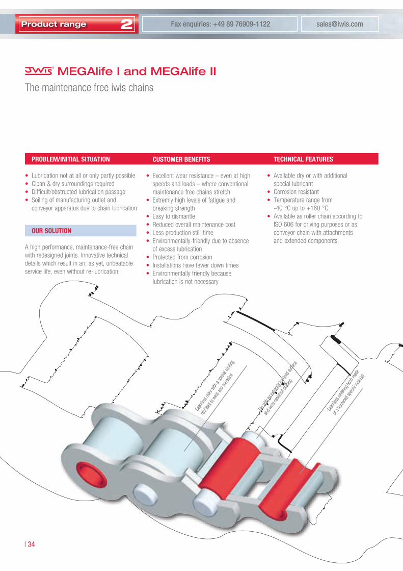
CuSTomer BeneFiTS
• Excellent wear resistance – even at high speeds and loads – where conventional maintenance free chains stretch
• Extremly high levels of fatigue and breaking strength
• Easy to dismantle• Reduced overall maintenance cost• Less production still-time• Environmentally-friendly due to absence
of excess lubrication• Protected from corrosion• Installations have fewer down times• Environmentally friendly because
lubrication is not necessary
TeChniCAl FeATureS
• Available dry or with additional special lubricant
• Corrosion resistant• Temperature range from
-40 °C up to +160 °C• Available as roller chain according to
ISO 606 for driving purposes or as conveyor chain with attachments and extended components.
MEGAlife I and MEGAlife IIThe maintenance free iwis chains
proBlem/iniTiAl SiTuATion
• Lubrication not at all or only partly possible• Clean & dry surroundings required• Difficult/obstructed lubrication passage• Soiling of manufacturing outlet and
conveyor apparatus due to chain lubrication
Seam
less r
oller w
ith a
specia
l coa
ting
resista
nt to
wear an
d corr
osion
Pin w
ith an
extre
mly hard
end s
urface
and w
ear-re
sistan
t coa
ting
Seam
less s
interi
ng bu
sh mad
e
of a h
arden
ed sp
ecial
materia
l
our SoluTion
A high performance, maintenance-free chain with redesigned joints. Innovative technical details which result in an, as yet, unbeatable service life, even without re-lubrication.

MEG
Alif
e ch
ains
Telephone enquiries: +49 89 76909-1600 www.iwis.com
�� |
2Li
fetim
e
Chain typeOperating hours
chai
n el
onga
tion
AreAS oF AppliCATion
• Packaging & Food Industry• Printing Industry• Conveyor-Equipment• Textile & Clothing Industry• Paper Manufacture &
Book Binding Industry• Electronic Industry &
Circuit Board Manufacture• Wood, Glass & Ceramic Industry• Medical technology
… and of course in all areas where re-lubri-cation is not at all or only partly possible.
highlighTS megAlife ii
• A distictive longer lifetime due to:• A considerably improved wear resistance as
a result of a special thermo-chemical treat-ment of the pins. Especially by fast running chain drives v > 3 m/s
highlighTS megAlife i
• Excellent wear resistance – even at high speeds and loads – where conventional maintenance free chains stretch
• Maintenance free under certain conditions• Extremly high levels of fatigue and
breaking strenght• Protected from corrosion• Easy to dismantle• Reduced overall maintenance cost• Less production still-time• Environmentally friendly because
lubrication is not necessary
com
pet
itive
mai
nten
ance
free
cha
ins
ME
GA
life
I
ME
GA
life
II
Standard chains
iwis standard chains
Maintenance free chains
MEGAlife
Trial without re-lubrication at high speeds.Graphic representation corresponds to iwis test results.

2Product range [email protected] enquiries: +49 89 76909-1122
| �6
Simplex
06 B-1 G 67 ML* 3/8” 9,525 5,72 11.000 9.000 0,28 0,41 8,53 8,20 12,90 16,70 6,35 3,31 - 50033917
08 B-1 L 85 ML 1/2” 12,70 7,75 22.000 18.000 0,50 0,70 11,30 12,20 16,90 18,50 8,51 4,45 - 50026256
10 B-1 M 106 ML 5/8” 15,875 9,65 25.000 22.400 0,67 0,95 13,28 14,40 19,50 20,90 10,16 5,08 - 50026257
12 B-1 M 127 ML 3/4” 19,05 11,75 30.000 29.000 0,89 1,25 15,62 16,40 22,70 23,60 12,07 5,72 - 50026258
16 B-1 M 1611 ML 1” 25,4 17,02 75.000 60.000 2,10 2,70 25,45 21,10 36,10 36,90 15,88 8,28 - 50028923
Duplex
06 B-2 D 67 ML 3/8” 9,525 5,72 19.000 16.900 0,56 0,78 8,53 8,20 23,40 24,60 6,35 3,31 10,24 50033832
08 B-2 D 85 ML 1/2” 12,70 7,75 40.000 32.000 1,00 1,35 11,30 12,20 30,80 32,40 8,51 4,45 13,92 50027439
10 B-2 D 106 ML 5/8” 15,875 9,65 50.000 44.500 1,34 1,85 13,28 14,40 36,00 37,50 10,16 5,08 16,59 50027509
12 B-2 D 127 ML 3/4” 19,05 11,75 60.000 57.800 1,78 2,50 15,62 16,40 42,10 43,00 12,07 5,72 19,46 50027457
16 B-2 D 1611 ML 1” 25,40 17,02 150.000 106.000 4,21 5,40 29,45 21,10 68,00 68,80 15,85 8,28 31,88 50033161
20 B-2 D 2012 ML 1 1/4” 31,75 19,56 210.000 170.000 5,84 7,36 29,01 25,40 79,70 82,90 19,05 10,19 36,45 50033771
Triplex
08 B-3 TR 85 ML 1/2” 12,70 7,75 58.000 47.500 1,50 2,00 11,30 12,20 44,70 46,30 8,51 4,45 13,92 50027510
10 B-3 TR 106 ML 5/8” 15,875 9,65 75.000 66.700 2,02 2,80 13,28 14,40 52,50 54,00 10,16 5,08 16,59 50027511
12 B-3 TR 127 ML 3/4” 19,05 11,75 90.000 86.700 2,68 3,80 15,62 16,40 61,50 62,50 12,07 5,72 19,46 50027512
16 B-3 TR 1611 ML 1” 25,40 17,02 220.000 160.000 6,32 8,00 25,45 21,10 99,20 100,70 15,88 8,28 31,88 50033628
Simplex/duplex - megAlife roller chains with straight side plates
10 B-1 M 106 ML-GL 5/8” 15,875 9,65 24.000 22.400 0,67 0,95 13,28 13,9 19,50 20,90 10,16 5,08 - 50035304
10 B-2 D 106 ML-GL 5/8” 15,875 9,65 47.500 44.500 1,34 1,85 13,28 13,9 36,00 37,50 10,16 5,08 16,59 50034083
12 B-2 D 127 ML-GL 3/4” 19,05 11,75 63.000 57.800 1,78 2,50 15,62 16,1 42,10 43,00 12,07 5,72 19,46 50034084
MEGAlife I roller chainsComplying with DIN 8187-1, ISO 606: 2004
ABp
C
D
g
BA d2
B Ad1
C
D
a
CC
DD
a 1 b 2
C
D
b 1
BA d2
B Ad1
B Ad1
BA d2
C
C
C
DD
D
a 1b 1
b 2
C
D
C
D
e a
C
C
C
DD
D
a 1 b 1b 2
C
D
C
D
ea
* also available in �0 m length (Art. �00���8�) �) Differing dimensions for cranked linksIf cranked links are fitted, it should be noted that the breaking strength of the chain my be reduced by approximately �0%.
DIN
ISO
no.
Pitc
hp
(”)
b 1(m
m)m
in.iw
is(N
)med
.
Weig
htp
erm
q(kg
/m)
b 2(m
m)m
in.
g(m
m)m
ax.
a 1(m
m)m
ax.1
)
a(m
m)m
ax.1
)
Rolle
rd 1
(mm
)max
.Pi
n d 2(m
m)m
ax.
e(m
m)
Artic
leNo
.
BreakingstrengthFB Innerlink Outerlink
Pitc
hp
(mm
)
Stan
dard
(N)m
in.
Brea
king
area
f(cm
2 )
Ref.
no.iw
is

MEG
Alif
e ch
ains
Telephone enquiries: +49 89 76909-1600 www.iwis.com
�� |
2
MEGAlife I conveyor chains with straight attachment platesbased on iwis roller chains complying with DIN 8187
Shape 102.1
08 B-1 L 85 ML 1) 1/2“ 12,7 13,0 19,0 4,2 11,6 25,5 39,4 5,4 – 18,0 1,5 4 5,2
10 B-1 M 106 ML 1) 5/8“ 15,875 16,3 24,3 5,2 13,6 30,1 46,6 6,8 – 24,0 1,6 5 5,3
12 B-1 M 127 ML 1) 3/4“ 19,05 19,1 29,1 6,2 15,9 35,3 54,7 7,4 – 28,0 1,8 5 5,5
16 B-1 M 1611 ML 1“ 25,4 24,6 36,6 8,2 25,9 57,8 89,7 10,4 – 36,2 3,0 6 8,2
Shape 103.1 and 103.2
08 B-1 L 85 ML 1) 1/2“ 12,7 17,0 23,0 4,2 11,6 25,5 39,4 5,4 12,7 23,6 1,5 4 5,2
10 B-1 M 106 ML 1) 5/8“ 15,875 16,3 25,8 5,2 13,6 30,1 46,6 7,5 15,8 31,0 1,6 5 5,3
12 B-1 M 127 ML 1) 3/4“ 19,05 18,3 29,0 6,2 15,9 35,3 54,7 9,0 19,0 37,2 1,8 5 5,5
16 B-1 M 1611 ML 1“ 25,4 28,45 41,55 8,2 25,9 57,8 89,7 10,35 25,4 47,2 3,0 6 8,2
�) also for the corresponding duplex and triplex chains �) Nominal pitch
Simplex chains Duplex chains Triplex chains
�0�.�
�0�.�� with threaded insert
�0�.�
�0�.�� with threaded insert
�0�.�
�0�.�� with threaded insert
B A B A B Ae1 e2 e3
STrAighT ATTAChmenTS
The types illustrated are also obtainable for connector and outer links for final assembly and repair.
Fitting attachments on one or both sides, on each outer link or at greater spacing is possible.
Other conveying chains and threaded inserts on request.
p(”)
p(m
m)
a(m
m)
b(m
m)
d(m
m)
Pitch2)
Sim
plexc
hains
e 1(m
m)
Duple
xcha
inse 2
(mm
)Tr
iplex
cha
inse 3
(mm
)g
(mm
)
i(mm
)
l(mm
)
s(m
m)
M(m
m)
mm
ax.
(mm
)
Threadedinsert
DIN
ISO
no.
Ref.
no.iw
is

2Product range [email protected] enquiries: +49 89 76909-1122
| �8
MEGAlife I conveyor chains with bent attachment platesbased on iwis roller chains complying with DIN 8187
�0�.� �0�.� �0�.�
Shape 202.1
08 B-1 L 85 ML 1) 1/2“ 12,7 8,0 4,2 27,6 39,6 41,5 53,5 55,4 67,4 5,4 14,0 - 18,1 1,5 4 5,2
10 B-1 M 106 ML 1) 5/8“ 15,875 9,0 5,2 33,6 49,6 50,1 66,1 66,6 82,6 6,8 18,0 - 24,0 1,6 5 5,3
12 B-1 M 127 ML 1) 3/4“ 19,05 10,0 6,2 41,1 61,1 60,5 80,5 79,9 99,9 7,4 22,6 - 28,0 1,8 5 5,5
16 B-1 M 1611 ML 1“ 25,4 16,0 8,2 53,9 77,9 85,8 109,8 117,7 141,7 10,4 26,0 - 36,2 3,0 6 8,2
Shape 203.1 and 203.2
08 B-1 L 85 ML 1) 2) 1/2“ 12,7 9,5 4,2 32,6 44,6 46,5 58,5 60,4 72,4 5,4 16,5 12,7 23,6 1,5 4 5,2
10 B-1 M 106 ML 1) 2) 5/8“ 15,875 11,0 5,2 30,6 49,6 47,1 66,1 63,6 82,6 7,5 18,0 15,8 31,0 1,6 5 5,3
12 B-1 M 127 ML 1) 2) 3/4“ 19,05 12,0 6,2 35,5 56,9 54,9 76,3 74,3 95,7 9,0 20,5 19,0 37,2 1,8 5 5,5
16 B-1 M 1611 ML 1“ 25,4 18,0 8,2 57,7 83,9 89,6 115,8 121,5 147,8 10,4 29,0 25,4 47,2 3,0 6 8,2
f1B A
B A
B Ae1
h
Simples chains
B A
B A
B A
f2
e2
h
Duplex chains
B A
B A
B A
f3
e3
h
Triplex chains
BenT ATTAChmenTS
The types illustrated are also obtainable for connector and outer link for final assembly and repair. Assembly of the bent attachments
�0�.�� with threaded insert �0�.�� with threaded insert �0�.�� with threaded insert
Conveyor chains D �6�� ML and TR �6�� ML on request �) Also for the corresponding duplex and triplex chains �) Assembly of the bent attachments also possible inward over the chain except when fitted on both sides to D 8� ML, D �06 ML and D ��� ML �) Nominal pitch
with threaded insert over the chain facing inwards is not possible. Fitting bent attach-ments on one or both sides on each outer
link or at greater spacing is possible.Other conveying chains and threaded inserts on request.
p(”)
p(m
m)
Pitch3)
c(m
m)
d(m
m)
e 1(m
m)
f 1(m
m)
e 2(m
m)
f 2(m
m)
e 3(m
m)
f 3(m
m)
g(m
m)
h(m
m)
i(mm
)
l(mm
)
s(m
m)
M(m
m)
mm
ax.
(mm
)
Threadedinsert
Simplexchains Duplexchains Triplexchains
DIN
ISO
no.
Ref.
no.iw
is

MEG
Alif
e ch
ains
Telephone enquiries: +49 89 76909-1600 www.iwis.com
�9 |
2
MEGAlife I conveyor chains with extended pinsbased on iwis roller chains complying with DIN 8187
pin type A, B, C
08 B-1 L 85 ML1) 1/2“ 12,7 7,75 8,51 4,45 25,5 10,0 40,5 25,0 13,0
10 B-1 M 106 ML1) 5/8“ 15,875 9,65 10,16 5,08 30,0 12,0 48,0 30,0 15,5
12 B-1 M 127 ML1) 3/4“ 19,05 11,75 12,07 5,72 36,0 15,0 51,0 30,0 15,5
16 B-1 M 1611 ML 1“ 25,4 17,02 15,88 8,28 53,8 20,0 68,5 35,0 18,0
�) For multiple chains on request �) Nominal pitch Other pin lengths and shapes on request
A
B A
B A
BA
BA
BA
d1
d2
b 1
l 1L 1
B
B A
B A
B
AB
A
BA
d1
d2
b 1
l 2L 2
C
B A
B A
B
AB
A
BA
d1
d2
b 1
l 3L 2
MEGAlife roller chains are also available in the following special versions:For example:
n MEGAlife transfer chains with high resistant plastic support brackets orn maintenance free power and free conveyor chains.
Contact us, our Sales Team will be pleased to advice you.
exTenDeD pinS
The types illustrated are also available as connecting links and outer links for final assembly and repair (C only as outer link).
SpeCiAl megAlife verSionS
p(”)
Pitch2)
p(m
m)
Inner
widt
hb 1
(mm
)
Rolld
iamet
erd 1
(mm
)
Pin
diam
eter
d 2(m
m)
L 1(m
m)
I 1(m
m)
L 2(m
m)
I 2(m
m)
I 3(m
m)
DesignA DesignBandC
DIN
ISO
no.
Ref.
no.iw
is1)

2Product range [email protected] enquiries: +49 89 76909-1122
| �0
MEGAlife II – Roller chainsComplying with DIN 8187-1, ISO 606: 2004
Simplex
06 B-1 G 67 ML-2 3/8” 9,525 11.000 9.000 0,28 0,41 5,72 8,53 8,20 12,90 14,10 6,35 3,31 - 50030791
08 B-1 L 85 ML-2 1/2” 12,70 22.000 18.000 0,50 0,70 7,75 11,30 12,20 16,90 18,50 8,51 4,45 - 50030461
10 B-1 M 106 ML-2 5/8” 15,875 27.500 22.400 0,67 0,95 9,65 13,28 14,40 19,50 20,90 10,16 5,08 - 50030462
12 B-1 M 127 ML-2 3/4” 19,05 34.000 29.000 0,89 1,25 11,75 15,62 16,40 22,70 23,60 12,07 5,72 - 50030463
16 B-1 M 1611 ML-2 1” 25,4 75.000 60.000 2,10 2,70 17,02 25,45 21,10 36,10 36,90 15,88 8,28 - 50030464
16 B-1 M 2012 ML-2 1” 25,4 120.000 95.000 5,84 7,36 19,56 29,10 26,60 77,00 79,70 19,05 10,17 36,45 50030465
Duplex
06 B-2 D 67 ML-2 3/8” 9,525 19.000 16.900 0,56 0,78 5,72 8,53 8,20 23,40 24,60 6,35 3,31 10,24 50031074
08 B-2 D 85 ML-2 1/2” 12,70 40.000 32.000 1,00 1,35 7,75 11,30 12,20 30,80 32,40 8,51 4,45 13,92 50030465
10 B-2 D 106 ML-2 5/8” 15,875 56.000 44.500 1,34 1,85 9,65 13,28 14,40 36,00 37,50 10,16 5,08 16,59 50030466
12 B-2 D 127 ML-2 3/4” 19,05 68.000 57.800 1,78 2,50 11,75 15,62 16,40 42,10 43,00 12,07 5,72 19,46 50030467
Triplex – ml-2 roller chains on request
Simplex – AnSi roller chains, complying with Din 8188-1, American standard, iSo 606: 2004
12 A-1 ANSI 60 M 128 AML-2 3/4“ 19,05 42.000 31.800 1,06 1,47 12,70 17,75 18,00 25,30 26,70 11,91 5,94 - 50031073
16 A-1ANSI 80 M 1610 AML-2 3/4” 19,05 68.000 56.700 1,79 2,57 15,88 22,40 22,80 32,00 33,90 15,88 7,94 - 50033770
ml-2 conveyor chains on request
�) Differing dimensions for cranked links. If cranked links are fitted, it should be noted that the breaking strength of the chain may be reduced by approximately �0%.
Nr. � Inner link Standard designation B
Nr. � Connecting link with spring clip Standard designation E
Nr. � Double cranked link Standard designation C
Nr. 8 Outer link Standard designation A
ABp
C
D
g
BA d2
B Ad1
C
D
a
CC
DD
a 1 b 2
C
D
b 1
BA d2
B Ad1
B Ad1
BA d2
C
C
C
DD
D
a 1b 1
b 2
C
D
C
D
e a
C
C
C
DD
D
a 1 b 1b 2
C
D
C
D
ea
Pitc
hp
(”)
Pitc
hp
(mm
)iw
is(N
)med
.St
anda
rd(N
)min.
Bear
inga
rea
f(cm
2 )W
eight
per
mq
(kg/m
)
b 1(m
m)m
in.b 2
(mm
)min.
g(m
m)m
ax.
a 1(m
m)m
ax.1
)
a(m
m)m
ax.1
)Ro
ller
d 1(m
m)m
ax.
Pin d 2(m
m)m
ax.
e(m
m)
Artic
leNo
.
BreakingstrengthFB
Innerlink Outerlink 5mVersions
inDiviDuAl ComponenTS AnD ConneCTing linkS
DIN
ISO
no.
Ref.
no.iw
is

MEG
Alif
e ch
ains
Telephone enquiries: +49 89 76909-1600 www.iwis.com
�� |
2
Nr. 8 Outer link Standard designation A
MEGAlife conveyor chainsExamples of special chain designs
megAlife conveyor chain with straight attachment plates megAlife conveyor chain with extendend pins
megAlife conveyor chain with bent attachment plates megAlife conveyor chain with special attachment plates

2Product range [email protected] enquiries: +49 89 76909-1122
| ��
iwis corrosion resistant chains consist of hardened, highly alloyed steels showing a good wear resistance and considerably higher fatigue and breaking strengths than for stainless chains. CR chains can be used in those applications where chains despite of extreme conditions need to remain flexible and stainless due to hygienic and visual reasons. A lubrication of CR chains is recommended.
CR Chains
| ��

Telephone enquiries: +49 89 76909-1600 www.iwis.com
�� |
2
�� |
2
2Product range [email protected] enquiries: +49 89 76909-1122
| ��
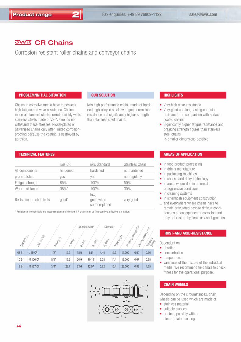
CR ChainsCorrosion resistant roller chains and conveyor chains
* Resistance to chemicals and wear-resistance of the iwis CR chains can be improved via effective lubrication.
proBlem/iniTiAl SiTuATion
Chains in corrosive media have to possess high fatigue and wear resistance. Chains made of standard steels corrode quickly whilst stainless steels made of V2-A steel do not withstand these stresses. Nickel-plated or galvanised chains only offer limited corrosion-proofing because the coating is destroyed by abrasion.
our SoluTion
iwis high performance chains made of harde-ned high-alloyed steels with good corrosionresistance and significantly higher strength than stainless steel chains.
highlighTS
• Very high wear-resistance• Very good and long-lasting corrosion
resistance - in comparison with surface-coated chains
• Significantly higher fatigue resistance and breaking strength figures than stainless steel chains smaller dimensions possible
AreAS oF AppliCATion
• In food product processing • In drinks manufacture• In packaging machines• In cheese and dairy technology• In areas where dominate moist
or aggressive conditions• In cleaning systems• In (chemical) equipment construction… and everywhere where chains have to
remain articulated despite difficult condi-tions as a consequence of corrosion and may not rust on hygienic or visual grounds.
TeChniCAl FeATureS
iwis CR iwis Standard Stainless Chain
All components hardened hardened not hardened
pre-stretched yes yes not regularly
Fatigue strength 85% 100% 50%
Wear resistance 95%* 100% 30%
low,Resistance to chemicals good* good when- very good surface-plated
ruST- AnD ACiD-reSiSTAnCe
Dependent on• duration• concentration• temperature• variations of the mixture of the individual
media. We recommend field trials to check fitness for the operational purpose.
ChAin wheelS
Depending on the circumstances, chain wheels can be used which are made of• stainless material• suitable plastics• or steel, possibly with an electro-plated coating.
08 B-1 L 85 CR 1/2” 16,9 18,5 8,51 4,45 12,2 16.000 0,50 0,70
10 B-1 M 106 CR 5/8” 19,5 20,9 10,16 5,08 14,4 18.000 0,67 0,95
12 B-1 M 127 CR 3/4” 22,7 23,6 12,07 5,72 16,4 22.000 0,89 1,25
Ref.
no.iw
is
DIN
ISO
no.
Pitc
hp
(”)
a 1(m
m)
a(m
m)
d 1(m
m)
d 2(m
m)
Plat
ehe
ight
Brea
king
stren
gth
FBBe
aring
are
af(
cm2 )
Weig
htq
(kh/m
)
DiameterOutsidewidth

CR
cha
ins
Telephone enquiries: +49 89 76909-1600 www.iwis.com
�� |
2
The mAjor pArAmeTerS CAuSing CorroSion
Influencing parametersTechnical outline: Which are the major factors causing corrosion?
• the medium in which the chain moves• the material the chain is made from• the construction of the component• the run time and way of application
• motion of medium• chemical condition• viscosity• pollution• pH-value (acidity)• temperature• pressure• concentration• solid deposit
meDium
• surface condition• other materials in environment• assembly
(welding and riveting)• design• protective measures• contact to medium
(partial or total dipping)
ConSTruCTion
• steel product• alloying additive• metallurgic condition
(heat treatment and mechanical treatment)
• pollution• composition
mATeriAl
• maintenance frequency• re-lubrication intervall• re-lubrication medium• aging of structure• tension development• change of inert layer?• temperature changes
Time inFluenCe
CorroSion FACTorS
There are four main factors causing corrosion:
noTe
All corrosion factors influence the corrosion resistance to the same extent. Please refer to our Technical Service Team for professional support.

2Product range [email protected] enquiries: +49 89 76909-1122
| �6
The new-generation iwis power and free conveyor chains L 88SF and M ��0SF combine an optimized load distribution with a more gentle and even transport of the conveyed goods. The synthetic chain guides are capable of carrying up to a double of the weight because the offset roller arrangement on which the chains run reduces the load on the guides by �0 %. iwis power and free conveyor chains allow easy positioning of the transported material at any point along the transport path and remove the need to start and stop the chain, thereby unsettling the conveyed material. The normal chain speed is 0.� to 0.� m/s. By fitting a simple acceleration rail, the conveying speed can be doubled (at locations in which material is not accumulated) without changing the chain speed. This is often used to separate goods.
Thanks to a special wax lubricant, the chains are low-maintenance. Applied only to the actual links during the assembly of the chains, the conveying rollers – and therefore the conveyed material – remain clean and have no contact with the lubricant. A special-pur-pose initial lubrication can be used for special-purpose applications. Conveying rollers made from hardened steel or antistatic plastic are available.
Power and free conveyor chains
| �6

Fax enquiries: +49 89 76909-1600 www.iwis.com
�� |
2
Power and free conveyor chains
�� |
2

2Product range [email protected] enquiries: +49 89 76909-1122
| �8
Power and free conveyor chains
our SoluTion
High performance power and free chains in accordance to the high iwis standard in a very wide range of designs.• L 88 SF and M 120 SF, the exclusive new
iwis generation of power and free conveyor chains. patented.
• Low-maintenance due to special wax lubrication (standard)
• Other initial lubrication for special applications on request
• Fully compatible with existing guides, deflector units and chain wheels
V
VF
Transport roller Light running rollers Chain guideRetarding area
Stop
V
VF
Acceleration rail
proBlem/iniTiAl SiTuATion
• Simple and reliable transport of a very wide range of workpieces and workpiece carriers
• Continuous conveying, accumulating, singling out and acceleration
highlighTS
• Gentle transportation and optimum support for the material being conveyed
• In accumulating operation, roller friction only (see figure below)
• The newly developed ”light running rollers” lead to a high reduction of drive power.
• Design patented by iwis. Please refer to diagram friction force
on page 52.
++ exCluSive ++
• All iwis 3/4” power and free conveyor chains are equipped with ”light running rollers”.
• Positioning the material transported with ease due to simple mounting points
• Chain no longer starts and stops jerkily• Twice the transport speed is possible due
to a simple acceleration rail (see figure below)
• Transport rollers made of either hardened steel or plastic (also antistatic)
• The outside of the chain is clean because only the articulated points are lubricated

Pow
er a
nd fr
ee c
onve
yor
chai
ns
Fax enquiries: +49 89 76909-1600 www.iwis.com
�9 |
2
Power and free conveyor chainsAdditional advantages
• Optimum load distribution – each pin bears load figure and
Power and free conveyor chains: new design
kg
Power and free conveyor chains: classic design
kg
Power and free conveyor chains: new design
Power and free conveyor chains: classic design
Dimensions - new power and free chains
L 88 SFK 12,70 27 9,2 14,50 18,70 16,00 1) 6 0,85
L 88 SFS 12,70 27 9,2 14,50 18,70 16,00 8 1,40
M 120 SFK 19,05 40 11,70 19,55 29,0 24,0 1) / 26,0 / 27,0 1) / 28,0 10 1,8
M 120 SFK 19,05 45 11,70 19,55 31,5 24,0 / 26,0 / 27,0 / 28,0 10 1,8
M 120 SFS 19,05 40 11,70 19,55 29,0 24,0 1) / 26,0 / 27,0 1) / 28,0 15 2,8
M 120 SFS 19,05 45 11,70 19,55 31,5 24,0 / 26,0 / 27,0 / 28,0 15 2,8
b b 4 e B
P
�) Supplied ex stockSFK - with plastic transport rollers SFS - with hardened steel transport rollers
ADDiTionAl ADvAnTAgeS oF The new power AnD Free Conveyor ChAinS l 88 SF AnD m 120 SF
• Better support and smoother running of the conveyed material due to the transport rollers having an offset arrangement figures and
Ref.
no.iw
is
Pitc
hp
(mm
)B
(mm
)
b(m
m)
b 4(m
m)
e(m
m)
Diam
eter
(mm
)
Load
ingc
apac
ity
perr
oller
(kg)
Weig
ht(k
g/m
)
TransportrollerChainwidth

2Product range [email protected] enquiries: +49 89 76909-1122
| �0
Power and free conveyor chainsSide bow power and free conveyor chains
b b 4 e B
P
contact surfaces
R min ��0
our SoluTion
contact lines
R min ��0
standard solution
our SoluTion
L 88 SF SB and M 120 SF-SB design – the solution for modular changes of direction in conveyor systems
highlighTS
• Extremely small minimum radius for curves 300 mm L 88 SF-SB 350 mm M 120 SF-SB
•
Optimum contact between bush and pin (bearing surface) in curve area (see illustration „our solution“ below)
L 88 SFS-SB 12,70 27 9,2 15,0 18,70 16,00 8 1,40
M 120 SFK-SB 19,05 40 11,70 20,10 29,0 24,0 / 26,0 / 27,0 / 28,0 10 1,8
M 120 SFS-SB 19,05 40 11,70 20,10 29,0 24,0 / 26,0 / 27,0 / 28,0 15 2,8
Ref.
no.iw
is
Pitc
hp
(mm
)
Transportroller
B(m
m)
b(m
m)
b 4(m
m)
e(m
m)
Chainwidth
Diam
eter
D(m
m)
Load
ingc
apac
ity
perr
oller
(kg)
Weig
ht(kg
)

Pow
er a
nd fr
ee c
onve
yor
chai
ns
Fax enquiries: +49 89 76909-1600 www.iwis.com
�� |
2
Power and free conveyor chainsDimensions - classic power and free conveyor chains (also available devoid of washers)
Design oS
M 127 SFK 19,05 40 27,5 11,75 15,62 19,55 11,0 24,0 26,0 28,0 10 12,07 5,72 2,3
M 127 SFS 19,05 40 27,5 11,75 15,62 19,55 11,0 24,0 26,0 28,0 – 12,07 5,72 3,1
Design m
M 127 SFK 19,05 40 27,5 11,75 15,62 19,55 11,0 24,0 26,0 28,0 10 12,07 5,72 2,3
M 127 SFK 19,05 43 29,0 11,75 15,62 19,55 11,0 24,0 26,0 1) 28,0 10 12,07 5,72 2,3
M 127 SFK 19,05 48 31,5 11,75 15,62 19,55 11,0 24,0 26,0 28,0 10 12,07 5,72 2,3
M 127 SFS 19,05 40 27,5 11,75 15,62 19,55 11,0 24,0 26,0 28,0 15 12,07 5,72 3,1
M 127 SFS 19,05 43 29,0 11,75 15,62 19,55 11,0 24,0 26,0 28,0 15 12,07 5,72 3,1
M 127 SFS 19,05 48 31,5 11,75 15,62 19,55 11,0 24,0 1) 26,0 28,0 15 12,07 5,72 3,1
M 1611 SFK 2) 25,4 65 44,9 17,02 25,45 32,0 16,5 38,5 – – 25 15,88 8,28 4,9
M 1611 SFS 2) 25,4 65 44,9 17,02 25,45 32,0 16,5 38,5 – – 30 15,88 8,28 7,2
Design lr
LR 165 SFK 2) 25,4 30,7 20,0 7,75 11,30 14,65 7,5 24,0 – – 6 8,52 4,45 1,3
LR 247 SFK 38,1 48 31,5 11,75 15,62 19,55 11,0 24,0 35 – 10 12,07 5,72 2,6
LR 247 SFS 38,1 48 31,5 11,75 15,62 19,55 11,0 24,0 35 – 10 12,07 5,72 2,6
LR 3211 SFK 2) 50,8 67,9 44,9 17,02 25,45 32,0 16,5 50,0 38,5 – 25 15,88 8,28 3,6
LR 3211 SFS 2) 50,8 67,9 44,9 17,02 25,45 32,0 16,5 50,0 38,5 – 30 15,88 8,28 7,6
�) Supplied ex stock �) Chains without light running rollersSFK - with plastic conveyor rollers SFS - with hardened steel conveyor rollers
Design M normal pitch Design LR double pitch
P
Db b4 e B
d1 d2
b 1
b 2
Design OS devoid of washers
Ref.
no.iw
is
Pitc
hp
(mm
)
Chain
widt
hB
(mm
)e
(mm
)
b 1(m
m)
b 2(m
m)
b 4(m
m)
Widt
hb
(mm
)
Diam
eter
Load
ingc
apac
ity
perr
oller
(kg)
Rolle
rd1(m
m)
Pin
d 2(m
m)
Weig
ht(kg
/m)
DiameterTransportroller
Connecting link
2Product range [email protected] enquiries: +49 89 76909-1122
| ��
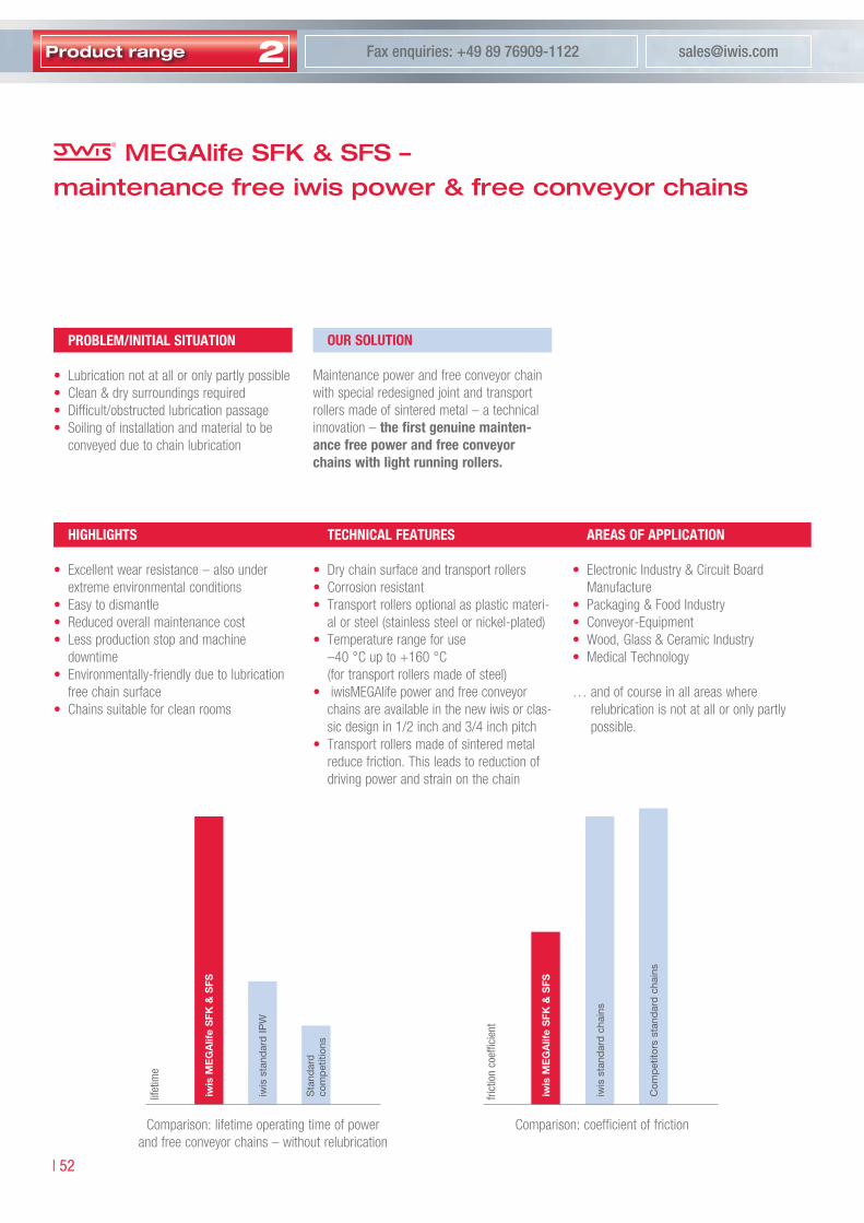
MEGAlife SFK & SFS –maintenance free iwis power & free conveyor chains
iwis
ME
GA
life
SFK
& S
FS
iwis
sta
ndar
dIP
W
Sta
ndar
dco
mp
etiti
ons
iwis
ME
GA
life
SFK
& S
FS
iwis
sta
ndar
dc
hain
s
Com
pet
itors
sta
ndar
dc
hain
s
frict
ion
coef
ficie
nt
proBlem/iniTiAl SiTuATion
• Lubrication not at all or only partly possible• Clean & dry surroundings required• Difficult/obstructed lubrication passage• Soiling of installation and material to be
conveyed due to chain lubrication
TeChniCAl FeATureS
• Dry chain surface and transport rollers• Corrosion resistant• Transport rollers optional as plastic materi-
al or steel (stainless steel or nickel-plated)• Temperature range for use
–40 °C up to +160 °C (for transport rollers made of steel)
• iwis MEGAlife power and free conveyor chains are available in the new iwis or clas-sic design in 1/2 inch and 3/4 inch pitch
• Transport rollers made of sintered metal reduce friction. This leads to reduction of driving power and strain on the chain
AreAS oF AppliCATion
• Electronic Industry & Circuit Board Manufacture
• Packaging & Food Industry• Conveyor-Equipment• Wood, Glass & Ceramic Industry• Medical Technology
… and of course in all areas where relubrication is not at all or only partly possible.
highlighTS
• Excellent wear resistance – also under extreme environmental conditions
• Easy to dismantle• Reduced overall maintenance cost• Less production stop and machine
downtime• Environmentally-friendly due to lubrication
free chain surface• Chains suitable for clean rooms
our SoluTion
Maintenance power and free conveyor chain with special redesigned joint and transportrollers made of sintered metal – a technical innovation – the first genuine mainten-ance free power and free conveyorchains with light running rollers.
lifet
ime
Comparison: lifetime operating time of power and free conveyor chains – without relubrication
Comparison: coefficient of friction

Pow
er a
nd fr
ee c
onve
yor
chai
ns
Fax enquiries: +49 89 76909-1600 www.iwis.com
�� |
2
L 88 SFK-ML 12,70 27 9,2 14,50 18,70 16,00 6 0,85
L 88 SFS-ML 12,70 27 9,2 14,50 18,70 16,00 8 1,40
M 120 SFK-ML 19,05 40 11,70 19,55 29,0 24,0 / 26,0 / 27,0 / 28,0 10 1,8
M 120 SFK-ML 19,05 45 11,70 19,55 31,5 24,0 / 26,0 / 27,0 / 28,0 10 1,8
M 120 SFS-ML 19,05 40 11,70 19,55 29,0 24,0 / 26,0 / 27,0 / 28,0 15 2,8
M 120 SFS-ML 19,05 45 11,70 19,55 31,5 24,0 / 26,0 / 27,0 / 28,0 15 2,8
b b 4 e B
P
Design oS
M 127 SFK-ML 19,05 40 27,5 11,75 15,62 19,55 11,0 24,0 26,0 28,0 10 – 12,07 5,72 2,3
M 127 SFS-ML 19,05 40 27,5 11,75 15,62 19,55 11,0 24,0 26,0 28,0 – 15 12,07 5,72 3,1
Design m
M 127 SFK-ML 19,05 40 27,5 11,75 15,62 19,55 11,0 24,0 26,0 28,0 10 – 12,07 5,72 2,3
M 127 SFK-ML 19,05 43 29,0 11,75 15,62 19,55 11,0 24,0 26,0 28,0 10 – 12,07 5,72 2,3
M 127 SFK-ML 19,05 48 31,5 11,75 15,62 19,55 11,0 24,0 26,0 28,0 10 – 12,07 5,72 2,3
M 127 SFS-ML 19,05 40 27,5 11,75 15,62 19,55 11,0 24,0 26,0 28,0 – 15 12,07 5,72 3,1
M 127 SFS-ML 19,05 43 29,0 11,75 15,62 19,55 11,0 24,0 26,0 28,0 – 15 12,07 5,72 3,1
M 127 SFS-ML 19,05 48 31,5 11,75 15,62 19,55 11,0 24,0 26,0 28,0 – 15 12,07 5,72 3,1
Dimensions - classic power and free conveyor chains
Design M normal pitch
SFK – with plastic conveyor rollers SFS – with hardened steel conveyor rollers
MEGAlife SFK & SFSDimensions - new power and free conveyor chains
P
Db b4 e B
d1 d2
b 1
b 2
Design OS devoid of washers
Ref.
no.iw
is
Pitc
hp
(mm
)
TransportRoller
B(m
m)
b(m
m)
b 4(m
m)
e(m
m)
Diam
eter
(mm
)
Load
ingc
apac
ity
perr
oller
(kg)
Weig
th(k
g/m
)
Chainwidth
Ref.
no.iw
is
Pitc
hp
(mm
)
Chain
ewi
dth
B(m
m)
e(m
m)
b 1(m
m)
b 2(m
m)m
ax.
b 4(m
m)m
ax.
Widt
hb
(mm
)
Diam
eter
Trag
fähigk
eitpr
oRo
lle(k
g)
Rolle
rd1(m
m)
Pin
d 2(m
m)
weigh
t(kg
/m)
TransportRoller Diameter
Connecting link

2Product range [email protected] enquiries: +49 89 76909-1122
| ��
Power and free conveyor chainsAccessories
Ref.no.iwis Pitchp(mm) B1(mm) X(mm) s(mm)
L 88 SF 12,7 4 15,5 10
M 120 SF-B40 19,05 8,3 20,7 15,0
M 127 SF-B40/B43 19,05 8,3 20,7 15,0
M 120 SF-B45 19,05 10,8 20,7 15,0
M 127 SF-B48 19,05 10,8 20,7 15,0
M 1611 SF 25,4 11,6 33,3 20,5
X
ds = d – �s d = p : (sin �80° : z) Recommended number of teeth minimum z = ��
The highly reduced friction force results in a substantial reduction of drive power for the complete unit.
ChAin wheelS
CompAriSon FriCTion ForCe ATTAChmenTS
Guide plates and filler pieces on request.
frict
ion
forc
e
chain type
chai
n w
ith
“lig
ht r
unni
ng r
olle
rs“
chai
nw
ithc
lass
icr
olle
rs
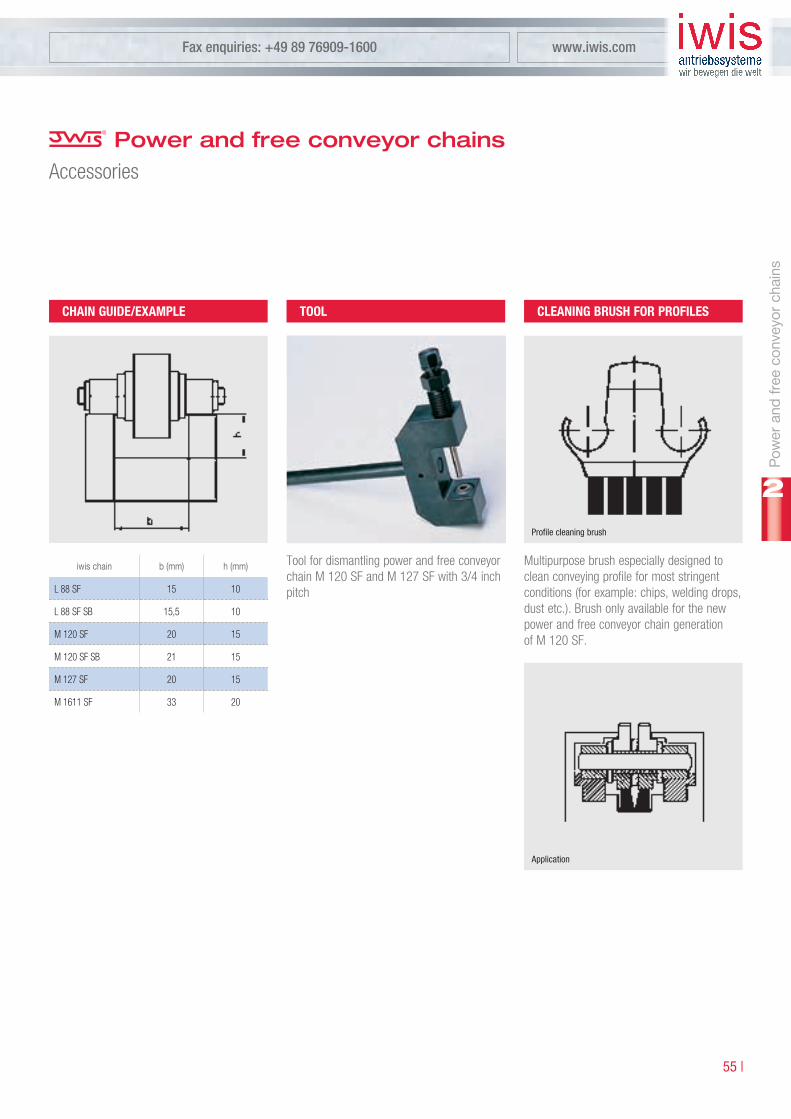
Pow
er a
nd fr
ee c
onve
yor
chai
ns
Fax enquiries: +49 89 76909-1600 www.iwis.com
�� |
2
iwischain b(mm) h(mm)
L 88 SF 15 10
L 88 SF SB 15,5 10
M 120 SF 20 15
M 120 SF SB 21 15
M 127 SF 20 15
M 1611 SF 33 20
Tool for dismantling power and free conveyor chain M 120 SF and M 127 SF with 3/4 inch pitch
Multipurpose brush especially designed to clean conveying profile for most stringent conditions (for example: chips, welding drops, dust etc.). Brush only available for the new power and free conveyor chain generation of M 120 SF.
Profile cleaning brush
Application
ChAin guiDe/exAmple Tool CleAning BruSh For proFileS
Power and free conveyor chainsAccessories

2Product range [email protected] enquiries: +49 89 76909-1122
| �6
As for every roller chain, the „bearing points“ of the power and free chain are also subject to natural wear. The correct tension, good guidance and effective relubrication are nee-ded to reduce this and therefore increase the service life of the chain.
A power and free conveyor chain works per-fectly at up to 2% extension caused by wear with the provison that it is constantly reten-sioned. Approximately 5% of the actual chain tensioning force occurring can be used asa guide value for pretensioning.
Power and free conveyor chains are given extremely effective initial lubrication in the works. The lubricant is used up in the course of time and effective and regular relubrication is necessary. During this process, care must be taken that the lubrication is undertaken at the correct points (= bearing points) and that the lubricant is able to creep.
Important criteria when selecting a power and free chain are:
• Loading on the transport rollers from the weight of the material being conveyed on them. The load-bearing strength per roller is stated in the tables. If the contact surface for the material being conveyed is uneven, it is necessary to estimate how many free rollers are actually load-bearing.
• Loading on the chain from tensile forces occurring in operation. The most important influencing dimensions are the weight of the material conveyed and the friction fac-tors.The following tensile forces occur in power and free chains:
• from friction resistance between roller and chain pin
• from friction resistance between transport rollers and chain bush when in accumulating operation
• from roller resistance when rolling the runners on to the chain guides and when rolling the conveyed materials on to the transport rollers.
... of power and free conveyor chains:
• In many areas of conveyor engineering• Where there are links in processing
and assembly lines• In warehouse engineering• In a wide range of material flow systems
… and everywhere where work-pieces, com-ponents for storage, pallets, containers, cra-tes etc. have to be conveyed, accumulated, accelerated and singled out in a simple way.
mAinTenAnCe guiDe For power AnD Free Conveyor ChAinS
inFormATion on The DeSign oF power AnD Free Conveyor ChAinS
AreA oF uSe...
Rough determination of the chain tensioning force F per chain strand:
F = [N]
µ = friction value 0.08-0.3 depending on: • material pairing
Steel/steel or plastic/steel • Condition of the friction surfaces:
dry or lubricated • Degree of contamination of the
friction surfaces
Q = Total weight conveyed [kg]n = Number of chain strands
The formula is valid for even distribution of the weight loading over the chain strands. If the conveyed material is not in full contact because of unevenness, an estimate has to be made as to what percentage of the length in contact is actually effective. The tensile strength per chain strand is correspondingly higher.
mAx. Conveyor lengTh
Depending on loading 25–30 m, parallel and exact guidance must be ensured.
µ · 9,81 · Q · 1,4n
Power and free conveyor chains

Pow
er a
nd fr
ee c
onve
yor
chai
ns
Fax enquiries: +49 89 76909-1600 www.iwis.com
�� |
2
Notes
Telephone enquiries: +49 89 76909-1600 www.iwis.com
�9 |
2
iwis offers an extensive program of special chains for various industrial applications and requirements. While the plate chain is being used wherever smooth and reliable conveying through very narrow bends is necessary, the transfer chains are utilized wherever gentle transportation is required. iwis grip chains are applied wherever plate and sheet type mate-rials are drawn in or off, transported or positioned. Additional iwis special conveyor chains: tube and can transport chains, pallet transporting chains, side bow chains, leaf chains anti back bend chains and hollow pin chains.
Special conveyor chains
�9 |
2

2Product range [email protected] enquiries: +49 89 76909-1122
| 60
Plate chains
AreAS oF AppliCATion
• Conveyor Technology• General Engineering• Packaging and Food Industry• Medical Technology and Pharmaceutical
industry• Linking machines and automation• Storage and buffer systems
…and everywhere where smooth and reliab-le conveying through very narrow bends is necessary.
highlighTS
• Plates pressed directly on to chain pins guarantee an absolutely flat transport track with no steps
• Optimum seal for the functioning areas of the chain
• Smooth contact area for workpieces due to engaging form of plates
• Extremely narrow radii of curvature are possible via specially designed plate shape
• Long conveying distances in most close-quartered space possible
• No risk of injury• Use of DIN chain wheels
proBlem/iniTiAl SiTuATion
Secure and smooth transportation and storage of workpieces and workpiece carriers using very narrow curved track.
our SoluTion
iwis high performance roller chain 3/4 x 7/16“ according to DIN 8187 with special plates pressed in precision in full contact (see sketch below).
12 B-1 M 127 Vers. 1 19,05 3,5 45 50 60 20
12 B-1 M 127 Vers. 2 19,05 3,5 59 80 150 30
16 B-1 M 1611 25,04 3,5 69,5 80 180 22
P(m
m)
s(m
m)
A(m
m)
B(m
m)
Rm
in.(m
m)
Ref.
no.iw
is
zmin.
DIN
ISO
No.

Sp
ecia
lcha
ins
Telephone enquiries: +49 89 76909-1600 www.iwis.com
6� |
2
08 B-1 L 85 TF 12,7 22.000 6250 0,82 19,8 15,2 8,0 12
10 B-1 M 106 TF 15,875 27.500 8000 1,18 24,8 17,5 9,5 26
12 B-1 M 127 TF 19,05 34.000 9750 1,59 29,8 19,8 11,0 43
Transfer chainsConveying, transporting, stop-start conveying of single parts, pallets…
proBlem/iniTiAl SiTuATion
Open transport chains:• Prone to interference from foreign bodies
and small parts• Often cause operational breakdowns• Increased risk of injury• Damage to material being conveyed• Adherence of dirt and dust
our SoluTion
The TF chains: iwis high performance roller chains with wear-resistant highly resistant plastic support brackets.Exclusive to iwis.
highlighTS
• Functional areas of the chain are com-pletely sealed, basic chain protected from penetration by foreign bodies
• Gentle transportation when free sensitive materials
• Precisely fitting cover prevents the risk of injury and operational breakdowns
• Chain is completely clean on the outside, therefore no dust is bonded to it.
• Initial lubrication with extremely high adhesion to the base chain, as standard
TeChniCAl FeATureS
• Supporting bracket: made of polyacetal resin
• Temperature range: 40°C to 100°C, up to 140°C for brief periods
• High wear resistance if the material being conveyed has a smooth surface
• Good chemical resistance • Shore hardness to DIN 53505: 85• Antistatic on request
AreA oF AppliCATion
• General engineering• Transport and storage technology• Packaging and food industry• Electronics and printed circuit board
industry• Electrical and household equipment• Medical technology and pharmaceutical
industry• Wood, glass and ceramics processing• Chemical and process technology• Printing and paper
…and everywhere where gentle transportation is required.
DIN
ISO
no.
Chain
Ref.
no.iw
is
max
.Bela
stung
pro
Kuns
tstof
f-bü
gel(N
)
Pitc
hp
(mm
)
Brea
king
stren
ght
iwis
F B(N
)Pe
rmiss
ible
we
ightl
oad
per
chain
stra
nd(N
)W
eight
(kg/m
)
Widt
hB
(mm
)
Heigh
tH(m
m)
h(m
m)
CarrierAttachment

2Product range [email protected] enquiries: +49 89 76909-1122
| 6�
B�
b
horizontal
h
H�
vertical
Connecting link: Same dimensions as chain
Transfer chainsConveying, transporting, stop-start conveying of single parts, pallets...
Connecting link
L 85 TF 20 7,5 3,1 15,4
M 106 TF 25 9,5 3,1 17,7
M 127 TF 30 11,3 2,9 20,0
SpeCiAl DeSign oF BASiC ChAin
• Nickel-plated• MEGAlife - maintenance-free• CR-corrosion resistant
only L 85 TF + M 106 TF
ChAin wheelS
• For TF-chains standard sprockets for chains according to DIN 8187 can be used
• By using chain wheels with number of teeth z >18, the chain is completly protected in the deflection zone.
verSionS inSTAlleD
ChAin guiDAnCe
ConneCTing link
The ends of the chain are connected with a pin block which has a separate plug-inplate pushed on to it. The two supporting brackets can be clipped on over the chain rivets by pushing down the chain in the right way. No locking spring is required. The rele-vant 2 supporting brackets are black in colour to make it easy to find the connecting link.
B 1Ref.no.iwis b h H 1

Sp
ecia
lcha
ins
Telephone enquiries: +49 89 76909-1600 www.iwis.com
6� |
2
TeChniCAl FeATureS
• Single or double chain 1/2 x 5/16 inch to DIN 8187-1/ ISO 606
• Gripper with 1 or 2 tips, special design on request
• Retaining force is dependent on material conveyed and spring design – differing number of coils and wire spring diameters obtainable
• The gripper opens by running against a control disc (e.g. chain wheel hub) which causes it to swivel out of the way to the outside
AreAS oF AppliCATion
• Packaging industry, especially foil packaging
• Electronic industry and manufacture of printed circuit boards
• Feeding in thin-walled sheet, plastics and other hard materials
… and everywhere where plate and sheet type materials are drawn in or off, transported or positioned, e.g. for punching, welding, filling, coating, cutting, stretching, shaping, sealing etc.
highlighTS
• Material to be transported is fed through in the best possible way because of the unique swivelling technique of the gripper
• Precise positioning of the material to be conveyed via reliable clamping
• Chain and clamping element with corrosion protection as standard
• Differing levels of spring force allow an extremely wide range of materials to be gripped gently
• Provided with initial lubrication, approved for use in the food industry, as standard
proBlem/iniTiAl SiTuATion
Reliable feeding, transporting and positioning of thin-walled materials with a large area.
our SoluTion
iwis high performance chains with wear- and corrosion-resistant clamping elementsPatent applied for.
Grip chainsGripping, retracting, transporting soft foils
Simple chain L 85 Grip 12,7 1,15
Double chain D 85 Grip 12,7 1,80
��,�
��,�
��,9
�9,9
y
�
��,�
�6,�
x8
�8
Dimensions x and y dependent on the spring used, on request
Ref.
no.iw
is
Pitc
hp
(mm
)
Weig
htq
(kg/m
)

2Product range [email protected] enquiries: +49 89 76909-1122
| 6�
Single strand chain M 128 AG 19,05 18,0 42.000 1,75
Double strand chain D 128 AG 19,05 18,0 84.000 3,50
Pallet transporting chains
Ref.
no.iw
is
Dimensions and figures not stated correspond to those for iwis chains M ��8 A SL or D ��8 A to DIN 8�88.
highlighTS
• Material to be transported can be posi-tioned throughout because of the straight side plates
• Roller chains with straight side plates for transporting a wide range of material
Pitc
hp
(mm
)
g(m
m)
Brea
king
stren
ghtF
B
iwis
mea
n(N
)
Weig
thq
(kg/m
)
Film TrAnSporT ChAin
• special design with button grip elementsDimensions x dependent on the spring used, on request
Simplex chain L 85 12,70 50035491
Simplex chain M 106 15,875 50034301Re
f.no
.iwis
Pitc
h
Orde
rNo.
Grip chainsGripping, retracting, transporting soft foils

Sp
ecia
lcha
ins
Telephone enquiries: +49 89 76909-1600 www.iwis.com
6� |
2
highlighTS
• Instead of being in contact with the line, the chain link is in overall contact through-out the curved area.
• Very narrow radii of curvature are possible because of symmetrical, tapered pins
• By using iwis straight and bent side plates suitable for universal use as conveyor chains
proBlem/iniTiAl SiTuATion
• Transporting and conveying on curved shape tracks
• Chains twisting when the shafts are at an angle to each other
• Change in the position of the material being transported e.g. from the horizontal to the vertical
our SoluTion
iwis high performance chains with specially designed chain link. Exclusive to iwis.
Side bow chainsTransporting, conveying, pulling on curved shape tracks
L 85 A-SB 12,7 16,8 17,8 425 10.000 600 1500 0,65 2, 4, 8
M 106 A-SB 15,875 21,0 22,3 500 18.000 900 2500 1,00 2, 4, 8
M 128 A-SB 19,05 26,3 27,7 750 26.000 1200 3700 1,50 2, 4, 8
Dimensions not stated correspond to those for iwis chains to DIN 8�88, American standard.
Ref.
no.iw
is
Pitc
hp
(mm
)
Max.permissiblechainpullpower
a 1(m
m)
a(m
m)
Mini
mum
radiu
s
R(m
m)
Brea
king
stren
ght
iwis
F B(N
)Co
ntinu
ous
(N)
Tran
sient
(N)
Weig
ht(kg
/m)
Conn
ectin
glin
ks
avail
able
Outerwidth

2Product range [email protected] enquiries: +49 89 76909-1122
| 66
M 128 A SL rückensteif 19,05 18,0 9 30 1,96
M 128 HB 19,05 18,0 25,5 6 36.500 1) 1,23
The principal dimensions correspond to iwis chain M ��8 A SL to DIN 8�88Smallest chain wheel: �0 teeth
Anti back bend chainsChain which is only flexible on one side for pushing lightweight loads and bridging short gaps without guides
Hollow pin chainSimple fixing of attachments and transverse struts
�) Breaking strength without pins inserted ��,�00 N
Ref.
no.iw
is
Pitc
hp
(mm
)
g(m
m)
h(m
m)
B(m
m)
Weig
ht(kg
/m)
Ref.
no.iw
is
g(m
m)
B(m
m)
D(m
m)
Brea
king
stren
gth
iwis
(N)
Weig
ht(kg
/m)
Pitc
hp
(mm
)
Special bush chain in accordance with roller chain 3/4 x 1/2 inch to DIN 8188-1 Hollow pins can be arranged at any desired interval.

Sp
ecia
lcha
ins
Telephone enquiries: +49 89 76909-1600 www.iwis.com
6� |
2
TeChniCAl FeATureS
• The bars are pinched on to the extended pins of the base chain using an adapter and secured by fins to prevent twisting
• The bar can be changed quickly and easily if a repair is needed by breading open the adapter with the iwis special tool (see illu-stration)
AreAS oF AppliCATion
• Everywhere where tubes and other thin-walled hollow bodies (cans) are transpor-ted, cleaned, painted, dried …
highlighTS
• Change the transport bars in the system without difficulty using the special iwis tool
• Not necessary to dismantle the chain• Adapter and bars made of highly alloyed,
corrosion-resistant steels with good elastic characteristics
• Long life in comparison to hollow pin chains thanks to the use of the iwis stan-dard roller chain
• Large standard of range of bar lengths• Different shapes for bar ends - nipples
made of aluminium or plastic are also available
• Freely selectable distance between the bars
• 3/4 inch chain also available in curved side design (M 128 ASB)
proBlem/iniTiAl SiTuATion
Gentle support and reliable transportation for thin-walled hollow bodies through several processing stations (cleaning, painting, drying...)
our SoluTion
iwis high performance chains – roller chains with rust-resistant, easy to change attach-ments. Exclusive to iwis.
Tube transport chains
08B-1 L 85 SL 12,7 300 8,0 22,0 4,0 8,0
10B-1 M 106 SL 15,875 300 8,0 22,0 4,0 8,0
12B-1 M 127 SL 19,05 300 8,0 22,0 4,0 8,0
12 A-1 ANSI 60 M 128 ASB 19,05 300 8,0 22,0 4,0 8,0
Please state the length L in any enquiry or order.
Ref.
no.iw
is
Pitc
hp
(mm
)
Lm
ax.(
mm
)
D 1(m
m)
m(m
m)
D 2(m
m)
D 3(m
m)
DIN
ISO
no.
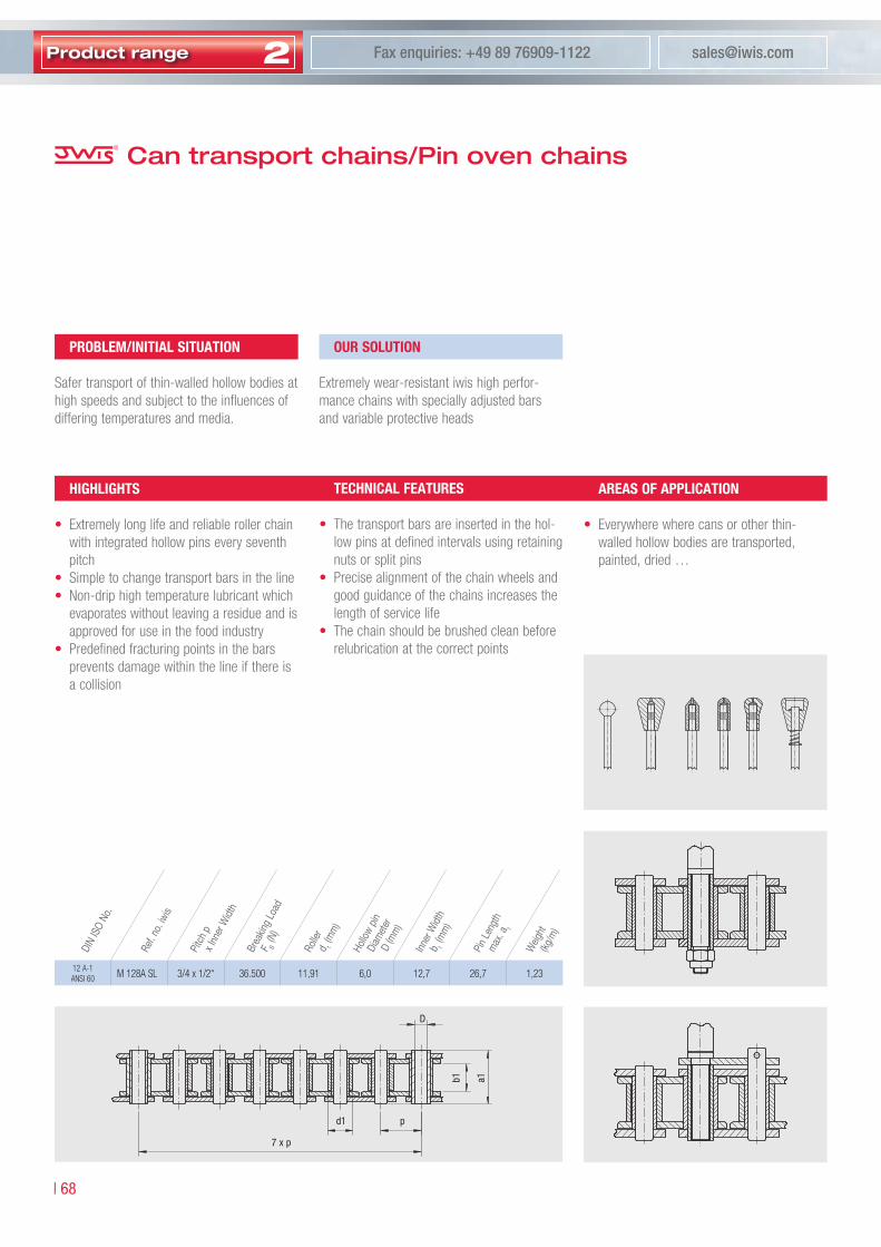
2Product range [email protected] enquiries: +49 89 76909-1122
| 68
D
d� p
� x p
b� a�
12 A-1 ANSI 60 M 128A SL 3/4 x 1/2“ 36.500 11,91 6,0 12,7 26,7 1,23
Can transport chains/Pin oven chains
proBlem/iniTiAl SiTuATion
Safer transport of thin-walled hollow bodies at high speeds and subject to the influences of differing temperatures and media.
our SoluTion
Extremely wear-resistant iwis high perfor-mance chains with specially adjusted bars and variable protective heads
TeChniCAl FeATureS
• The transport bars are inserted in the hol-low pins at defined intervals using retaining nuts or split pins
• Precise alignment of the chain wheels and good guidance of the chains increases the length of service life
• The chain should be brushed clean before relubrication at the correct points
AreAS oF AppliCATion
• Everywhere where cans or other thin-walled hollow bodies are transported, painted, dried …
highlighTS
• Extremely long life and reliable roller chain with integrated hollow pins every seventh pitch
• Simple to change transport bars in the line• Non-drip high temperature lubricant which
evaporates without leaving a residue and is approved for use in the food industry
• Predefined fracturing points in the bars prevents damage within the line if there is a collision
Ref.
no.iw
is
Weig
ht(kg
/m)
DIN
ISO
No.
Pitc
hp
xInn
erW
idth
Brea
king
Load
F B(N
)
Rolle
rd 1
(mm
)
Hollo
wpin
Di
amet
erD
(mm
)
Inner
Widt
hb 1
(mm
)
Pin
Leng
thm
ax.a
1

Sp
ecia
lcha
ins
Telephone enquiries: +49 89 76909-1600 www.iwis.com
69 |
2
leaf chains
FL 522 – 8,0 2 x 2 5.000 0,05 0,15 2,31 5,6 – 6,3 1,0 6,2 – 16,0 – 15,0 10,0 – –
FL 523 – 8,0 2 x 3 7.000 0,05 0,19 2,31 6,7 – 6,3 1,0 6,2 – 16,0 – 15,0 10,0 – –
FL 623 1) 3/8“ 9,525 2 x 3 10.000 0,08 0,32 3,31 8,3 – 8,1 1,2 6,2 – 16,0 – 15,0 10,0 – –
FL 623 b 1) 3/8“ 9,525 2 x 3 20.000 0,20 0,46 3,31 10,9 – 8,2 2,0 6,2 – – – – – – –
FL 823 b 1/2“ 12,70 2 x 3 28.000 0,18 0,65 4,45 12,4 – 10,8 2,0 8,2 – 18,0 – 20,0 11,0 – –
FL 834 a 1/2“ 12,70 3 x 4 21.000 0,17 0,42 3,68 13,1 – 9,1 1,5 8,2 – 18,0 – 20,0 11,0 – –
FL 834 b 1/2“ 12,70 3 x 4 42.000 0,27 0,91 4,45 16,5 – 10,8 2,0 8,2 – 18,0 – 20,0 11,0 – –
FL 845 a 1/2“ 12,70 4 x 5 34.000 0,24 0,67 3,68 16,9 25 9,1 1,6 8,2 12,2 18,0 25,0 20,0 11,0 30,0 15,0
FL 845 b 1/2“ 12,70 4 x 5 52.000 0,32 1,00 4,45 19,0 25 10,8 1,8 8,2 12,2 18,0 25,0 20,0 11,0 30,0 15,0
FL 866 a 1/2“ 12,70 6 x 6 44.000 0,36 0,88 3,68 21,7 28 9,1 1,6 8,2 12,2 18,0 25,0 20,0 11,0 30,0 15,0
FL 866 bd 1/2“ 12,70 3 x 3 2) 62.000 0,40 1,17 4,45 20,6 28 10,8 1,5 8,2 12,2 18,0 25,0 20,0 11,0 30,0 15,0
FL 1044 bd 5/8“ 15,875 2 x 2 2) 57.000 0,37 1,12 5,08 16,8 28 13,7 1,8 10,4 16,2 20,0 35,0 25,0 12,0 45,0 21,0
FL 1066 bd 5/8“ 15,875 3 x 3 2) 86.000 0,55 1,68 5,08 24,0 35 13,7 1,8 10,4 16,2 20,0 35,0 25,0 12,0 45,0 21,0
FL 1266 bd 3/4“ 19,05 3 x 3 2) 115.000 0,76 2,18 5,72 30,0 40 14,9 2,2 10,4 16,2 20,0 35,0 25,0 12,0 45,0 21,0
FL 1644 d 1“ 25,40 2 x 2 2) 157.000 1,00 2,92 8,28 28,0 40 20,8 3,0 12,2 18,2 25,0 40,0 30,0 15,0 50,0 24,0
FL 1666 d 1“ 25,40 3 x 3 2) 231.000 1,50 4,35 8,28 41,0 50 20,8 3,0 12,2 18,2 25,0 40,0 30,0 15,0 50,0 24,0
Leaf chains
�) Straight side plates �) double
End link design A
End link design B (from combination �x�)Example for the design of a deflection roller
Inner roller width: b = a
1 · 1,15
Minimum base diameter: d
f min = p · 5
Where possible, fit relatively large diameter
iwis leaf chains are manufactured from precision iwis chain parts to DIN 8187.
The chain selection will be deter-mined by the size and frequency of shock loading and the appropriate national lifting regulations.
Ref.
no.iw
is
p(“)
p(m
m)
Plat
eco
mbin
ation
Arra
ngem
ent
Bear
inga
rea
f(cm
2 )
Brea
king
load
F B
iwis
min
(N)
Weig
htq
(kg/
m)
Bear
ingp
india
met
er
d 2(m
m)
a 1(m
m)
a(m
m)
Plat
ehe
ightg
1(m
m)
Plat
eth
ickne
sss
(mm
)d 3
(mm
)
d 4(m
m)
g 2(m
m)
g 3(m
m)
u 1(m
m)
u 2(m
m)
u 3(m
m)
u 4(m
m)
EndlinkdimensionsOverallwidthPitch

Telephone enquiries: +49 89 76909-1600 www.iwis.com
�� |
3
The form of the Sprockets is determined by the following factors: type of chain, the number of teeth, the torque to be transmitted and the application. A distinction is drawn between sprockets and chain plate wheels for roller chains according to Norm (e.g. DIN 8�8�/8�88) and special versions. Sprockets with hub allow the transmission of a higher torque, whereas plate wheels may be used only for the transmission of small torques. For a detailed instruc-tion regarding design and construction of sprockets and plate wheels, please view of our iwis chain engineering hand book.
Sprockets
�� |
3
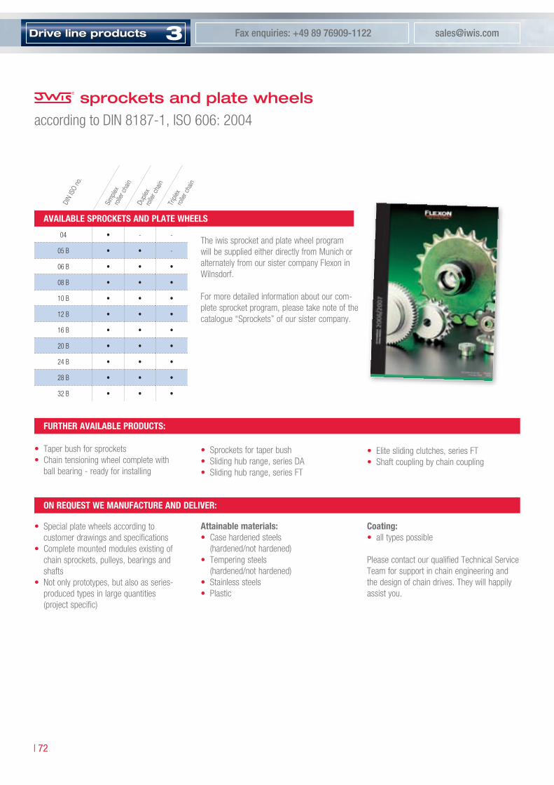
3Drive line products [email protected] enquiries: +49 89 76909-1122
| ��
• Special plate wheels according to customer drawings and specifications
• Complete mounted modules existing of chain sprockets, pulleys, bearings and shafts
• Not only prototypes, but also as series- produced types in large quantities (project specific)
sprockets and plate wheelsaccording to DIN 8187-1, ISO 606: 2004
The iwis sprocket and plate wheel program will be supplied either directly from Munich or alternately from our sister company Flexon in Wilnsdorf.
For more detailed information about our com-plete sprocket program, please take note of the catalogue “Sprockets” of our sister company.
on requeST we mAnuFACTure AnD Deliver:
Attainable materials:• Case hardened steels
(hardened/not hardened)• Tempering steels
(hardened/not hardened)• Stainless steels• Plastic
Coating:• all types possible
Please contact our qualified Technical Service Team for support in chain engineering and the design of chain drives. They will happily assist you.
04 • - -
05 B • • -
06 B • • •
08 B • • •
10 B • • •
12 B • • •
16 B • • •
20 B • • •
24 B • • •
28 B • • •
32 B • • •
DIN
ISO
no.
Sim
plex
rolle
rcha
in
Duple
xro
llerc
hain
Tripl
ex
rolle
rcha
in
AvAilABle SproCkeTS AnD plATe wheelS
FurTher AvAilABle proDuCTS:
• Taper bush for sprockets• Chain tensioning wheel complete with
ball bearing - ready for installing
• Sprockets for taper bush• Sliding hub range, series DA• Sliding hub range, series FT
• Elite sliding clutches, series FT• Shaft coupling by chain coupling
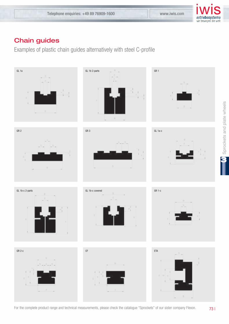
Sp
rock
ets
and
pla
tew
heel
s
Telephone enquiries: +49 89 76909-1600 www.iwis.com
�� |
3
GL �a GL �b �-parts GR �
Chain guidesExamples of plastic chain guides alternatively with steel C-profile
GR � GR � GL �a-c
GL �b-c �-parts GL �b-c covered GR �-c
GR �-c CF ETA
For the complete product range and technical measurements, please check the catalogue “Sprockets” of our sister company Flexon.
Telephone enquiries: +49 89 76909-1600 www.iwis.com
�� |
3
iwis tools facilitate the breaking and riveting of roller chains pursuant to DIN 8�8�/8�88 and the iwis norm and are useful for workshop use. The iwis tool product range also includes repairing tools for tube and can conveyor chains, power and free conveyor chains and plate chains.
Tools
�� |
3
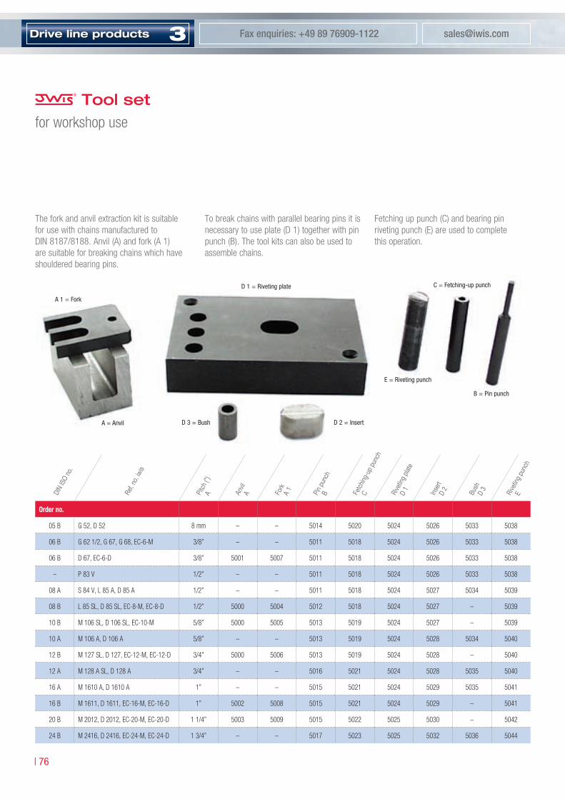
3Drive line products [email protected] enquiries: +49 89 76909-1122
| �6
Tool set for workshop use
The fork and anvil extraction kit is suitable for use with chains manufactured to DIN 8187/8188. Anvil (A) and fork (A 1) are suitable for breaking chains which have shouldered bearing pins.
To break chains with parallel bearing pins it is necessary to use plate (D 1) together with pin punch (B). The tool kits can also be used to assemble chains.
Fetching up punch (C) and bearing pin riveting punch (E) are used to complete this operation.
order no.
05 B G 52, D 52 8 mm – – 5014 5020 5024 5026 5033 5038
06 B G 62 1/2, G 67, G 68, EC-6-M 3/8” – – 5011 5018 5024 5026 5033 5038
06 B D 67, EC-6-D 3/8” 5001 5007 5011 5018 5024 5026 5033 5038
– P 83 V 1/2” – – 5011 5018 5024 5026 5033 5038
08 A S 84 V, L 85 A, D 85 A 1/2” – – 5011 5018 5024 5027 5034 5039
08 B L 85 SL, D 85 SL, EC-8-M, EC-8-D 1/2” 5000 5004 5012 5018 5024 5027 – 5039
10 B M 106 SL, D 106 SL, EC-10-M 5/8” 5000 5005 5013 5019 5024 5027 – 5039
10 A M 106 A, D 106 A 5/8” – – 5013 5019 5024 5028 5034 5040
12 B M 127 SL, D 127, EC-12-M, EC-12-D 3/4” 5000 5006 5013 5019 5024 5028 – 5040
12 A M 128 A SL, D 128 A 3/4” – – 5016 5021 5024 5028 5035 5040
16 A M 1610 A, D 1610 A 1” – – 5015 5021 5024 5029 5035 5041
16 B M 1611, D 1611, EC-16-M, EC-16-D 1” 5002 5008 5015 5021 5024 5029 – 5041
20 B M 2012, D 2012, EC-20-M, EC-20-D 1 1/4” 5003 5009 5015 5022 5025 5030 – 5042
24 B M 2416, D 2416, EC-24-M, EC-24-D 1 3/4” – – 5017 5023 5025 5032 5036 5044
Pitc
h(”)
ARef.
no.iw
is
DIN
ISO
no.
Anvil
A Fork
A1
Pin
punc
hB Fe
tchin
g-up
pun
ch
C Rive
ting
plate
D1
Inser
tD
2
Bush
D3
Rive
ting
punc
hE
A � = Fork
A = Anvil
C = Fetching-up punchD � = Riveting plate
D � = Bush D � = Insert
E = Riveting punch
B = Pin punch

Tool
s
Telephone enquiries: +49 89 76909-1600 www.iwis.com
�� |
3
The fork (A 1) is placed through the chain at the outer link which is to be removed. The fork is then supported by the anvil and the bearing pins are driven through the chain using punch (B) . Multiple strand chains can also be broken in this way, the fork should then be placed in the top strand of the chain.
The outer link to be broken has to be placed over the holes in the riveting plate (D). The bearing pins are hammered flush with the outer plate and then driven through the chain with pin punch (B) whose diameter must be smaller than that of the bearing pin . To assist when breaking large pitch chains it is recommended that the rivet head is initially ground away.
The procedure used is common to both shouldered and parallel bearing pin chains.The new riveting link connects the two inner links. This connecting link is supported by an insert in riveting plate (D) .
A new outer link plate is fitted using fetching-up punch (C) . With parallel bearing pin chain it is possible to over fit the outer link plate on the bearing pins. It is necessary to check that the joint remains free and easily moveble after fitting.
The newly fitted outer link then requires the bearing pin ends to be riveted. This is done with riveting punch (E) .
e
Chain link with shouldered pinChain with parallel bearing pin
BreAking (pArAllel BeAring pin) ASSemBly BreAking (ShoulDereD BeAring pin)
ApplicationsBreaking chains and chain assembly
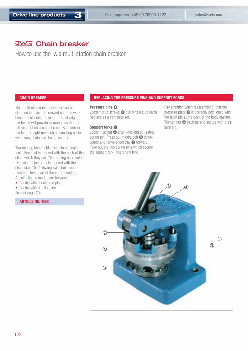
3Drive line products [email protected] enquiries: +49 89 76909-1122
| �8
Chain breaker How to use the iwis multi station chain breaker
pressure pins :Loosen grub screws pull pins out upwards. Replace as a complete set.
Support forks :Loosen top nut after knocking out safety spring pin. Press out middle bolt down-wards and remove tool tray forward. Take out the two spring pins which secure the support fork. Insert new fork.
Pay attention when reassembling, that the pressure plate is correctly positioned with the latch pin at the back of the body casting. Tighten nut back up and secure with pres-sure pin.
ChAin BreAker
This multi-station rivet extractor can be clamped in a vice or screwed onto the work-bench. Positioning it along the front edge of the bench will provide clearance so that the full range of chains can be cut. Supports to the left and right make chain handling easier when long chains are being inserted.
The rotating head holds five sets of ejector tools. Each set is marked with the pitch of the chain which they cut. The rotating head holds five sets of ejector tools marked with the chain size. The following iwis chains can thus be taken apart at the correct setting. A distinction is made here between:• Chains with shouldered pins• Chains with parallel pins(look at page 79)
e
replACing The preSSure pinS AnD SupporT ForkS
ArTiCle no. 4500

Tool
s
Telephone enquiries: +49 89 76909-1600 www.iwis.com
�9 |
3
For breaking chains with shouldered pins the chain is fitted into the appropriate fork according to pitch, and the complete outer link is pressed out when the lever is pulled. It is important that the chain is fully located in the fork.
DINISOno. Ref.no.iwis Pitch Adjustment
06 B - 2 D 67 3/8 x 7/32” 3/8”
06 B - 3 Tr 67 3/8 x 7/32” 3/8”
08 B - 1 L 85 SL 1/2 x 5/16” 1/2”
08 B - 2 D 85 SL 1/2 x 5/16” 1/2”
08 B - 3 Tr 85 1/2 x 5/16” 1/2”
10 B - 1 M 106 SL 5/8 x 3/8” 5/8”
10 B - 2 D 106 SL 5/8 x 3/8” 5/8”
10 B - 3 Tr 106 5/8 x 3/8” 5/8”
12 B - 1 M 127 SL 3/4 x 7/16” 3/4”
12 B - 2 D 127 3/4 x 7/16” 3/4”
12 B - 3 Tr 127 3/4 x 7/16” 3/4”
Chain link with shouldered pin
For breaking chains with parallel pins it is necessary to grind off the rivet heads on one side of the chain. Afterwards the outer link is pressed out as above.
If a grinding device is not available the rivets can be knocked out with a punch after the outer sideplate has been pressed off. Here the bushes must be well supported to prevent them coming off the inner plates when the
The iwis multi-station chain breaker can also be used to cut conveyor chains with straight or bent attachments plates of corresponding size. It is not suitable for 3/8 x 5/32” chains.
Chains with parallel bearing pins
DINISOno. ANSItype Ref.no.iwis Pitch Adjustment
06 B - 1 - G 67 3/8 x 7/32” 3/8”
08 A - 1 ANSI 40 L 85 A 1/2 x 5/16” 1/2”
08 A - 2 ANSI 40-2 D 85 A 1/2 x 5/16” 1/2”
08 A - 3 ANSI 40-3 Tr 85 A 1/2 x 5/16” 1/2”
10 A - 1 ANSI 50 M 106 A 5/8 x 3/8” 5/8”
10 A - 2 ANSI 50-2 D 106 A 5/8 x 3/8” 5/8”
10 A - 3 ANSI 50-3 Tr 106 A 5/8 x 3/8” 5/8”
12 A - 1 ANSI 60 M 128 A SL 3/4 x 1/2” 3/4”
12 A - 2 ANSI 60-2 D 128 A 3/4 x 1/2” 3/4”
12 A - 3 ANSI 60-3 Tr 128 A 3/4 x 1/2” 3/4”
A) ChAinS wiTh ShoulDereD pinS
B) ChAinS wiTh pArAllel pinS
pressure pins and support forks are being replaced. Although chains can be taken apart without pregrinding the riveted head the dan-ger of damage to the bush bore does exist.This could reduce chain life.
Chain breaker How to use the iwis multi-station chain breaker

3Drive line products [email protected] enquiries: +49 89 76909-1122
| 80
Reparing tool for tube and can conveyor chainsReplacement of conveyor pins
Chain Pitch D1 m
L 85 SL 12,7 8,0 22,0
M 106 SL 15,876 8,0 22,0
M 127 SL 19,05 8,0 22,0
M 128 ASL 19,05 10,0 22,0
M 128 A-SB 19,05 10,0 22,0
SpeCiAl Tool
The above represented iwis tool has been specially developed to repair tube and can conveyor chains. It allows easy replacement of conveyor pins on already installed chains, types L 85 SL, M 106 SL, M 127 SL, M 128 ASL and M 128 A-SB (changeable).
ArTiCle no. 40000421

Tool
s
Telephone enquiries: +49 89 76909-1600 www.iwis.com
8� |
3
How to employ itRemoval and fastening of pin adapter
The new adapter is set onto the extended pin. Seize it with the gripping jaws and clamp it with the tool. Thus repaired, the chain is operational again.
Insert the adapter into the jaws and break it by closing the tool. If necessary, repeat the action after 45° rotation. Once the adapter has been broken, remove the pin.
remove pin ADApTer Fixing oF A new Conveyor pin
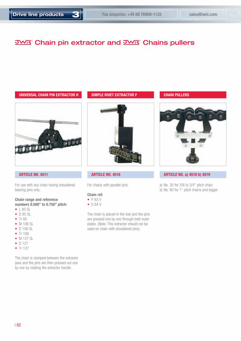
3Drive line products [email protected] enquiries: +49 89 76909-1122
| 8�
Chain pin extractor and Chains pullers
For use with any chain having shouldered bearing pins only.
Chain range and referencenumbers 0.500” to 0.750” pitch:• L 85 SL • D 85 SL • Tr 85• M 106 SL • D 106 SL • Tr 106• M 127 SL • D 127 • Tr 127
The chain is clamped between the extractor jaws and the pins are then pressed out one by one by rotating the extractor handle.
For chains with parallel pins.
Chain ref: • P 83 V • S 84 V
The chain is placed in the tool and the pins are pressed one by one through both outer plates. (Note: This extractor should not be used on chain with shouldered pins).
a) No. 35 for 3/8 to 3/4” pitch chainb) No. 80 for 1” pitch chains and bigger
univerSAl ChAin pin exTrACTor h
ArTiCle no. 4511 ArTiCle no. 4516 ArTiCle no. a) 4518 b) 4519
Simple riveT exTrACTor F ChAin pullerS
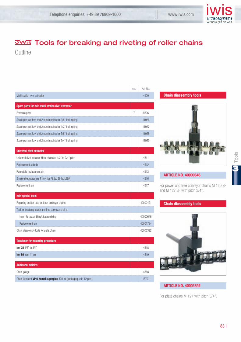
Tool
s
Telephone enquiries: +49 89 76909-1600 www.iwis.com
8� |
3
no. Art-No.
Multi-station rivet extractor 4500
Spare parts for iwis multi station rivet extractor
Pressure plate 7 9806
Spare-part-set fork and 2 punch points for 3/8” incl. spring 11926
Spare-part-set fork and 2 punch points for 1/2” incl. spring 11927
Spare-part-set fork and 2 punch points for 5/8” incl. spring 11928
Spare-part-set fork and 2 punch points for 3/4” incl. spring 11929
universal rivet extractor
Universal rivet extractor H for chains of 1/2” to 3/4” pitch 4511
Replacement spindle 4512
Reversible replacement pin 4513
Simple rivet extractors F no.4 for F82V, S84V, L85A 4516
Replacement pin 4517
iwis special tools
Repairing tool for tube and can conveyor chains 40000421
Tool for breaking power and free conveyor chains
Insert for assembling/disassembling 40000646
Replacement pin 40001734
Chain diassembly tools for plate chain 40003392
Tensioner for mounting procedure
no. 35 3/8” to 3/4” 4518
no. 80 from 1” on 4519
Additional articles
Chain gauge 4568
Chain lubricant vp 6 kombi superplus 400 ml (packaging unit: 12 pcs.) 15701
Tools for breaking and riveting of roller chainsOutline
For power and free conveyor chains M 120 SF and M 127 SF with pitch 3/4”.
Chain diassembly tools
ArTiCle no. 40000646
For plate chains M 127 with pitch 3/4”.
Chain diassembly tools
ArTiCle no. 40003392

3Drive line products [email protected] enquiries: +49 89 76909-1122
| 8�
DINISONo. No. Art-No.
Anvil A
08 B, 10 B, 12 B 2 5000
06 B 3 5001
16 B 4 5002
20 B 5 5003
Fork A1
08 B 2 5004
10 B 3 5005
12 B 4 5006
06 B 6 5007
16 B 8 5008
20 B 9 5009
- 10 5010
Pin punch B
06 B, 08 A 1 5011
08 B 2 5012
10 B 3 5013
05 B 4 5014
20 B, 16 A, 16 B 5 5015
12 A 6 5016
24 B 7 5017
Fetching up punch C
06 B, 08 B, 08 A 1 5018
10 B, 10 A, 12 B 2 5019
- 3 5020
16 B, 12 A, 16 A 4 5021
20 B 5 5022
24 B 6 5023
Reveting plate D1
05 B-16 B, 08 A-16 A 1 5024
20 B, 24 B 2 5025
DINISONo. No. Art-No.
Insert D2
05 B, 06 B 1 5026
08 A, 08 B, 16 B 2 5027
10 A, 12 A, 12 B 3 5028
16 A, 16 B 4 5029
20 B 5 5030
- 6 5031
24 B 8 5032
Bush D3
05 B, 06 B 1 5033
08 A, 10 A 2 5034
12 A, 16 A 3 5035
24 B 4 5036
- 5 5037
Riveting punch F
05 B, 06 B 1 5038
08 A, 08 B, 10 B 2 5039
10 A, 12 A, 12 B 3 5040
16 A, 16 B 4 5041
20 B 5 5042
- 6 5043
24 B 7 5044
ToolsOutline

Tool
s
Telephone enquiries: +49 89 76909-1600 www.iwis.com
8� |
3
Notes

Telephone enquiries: +49 89 76909-1600 www.iwis.com
8� |
3
Automatic chain tensioners compensate the chain elongation in the machines and conveyor systems and that way further the run time of the applied chain. iwis chain tensioners are made from high quality materials. Depending on the application various types are available.
Automatic tensioners
8� |
3
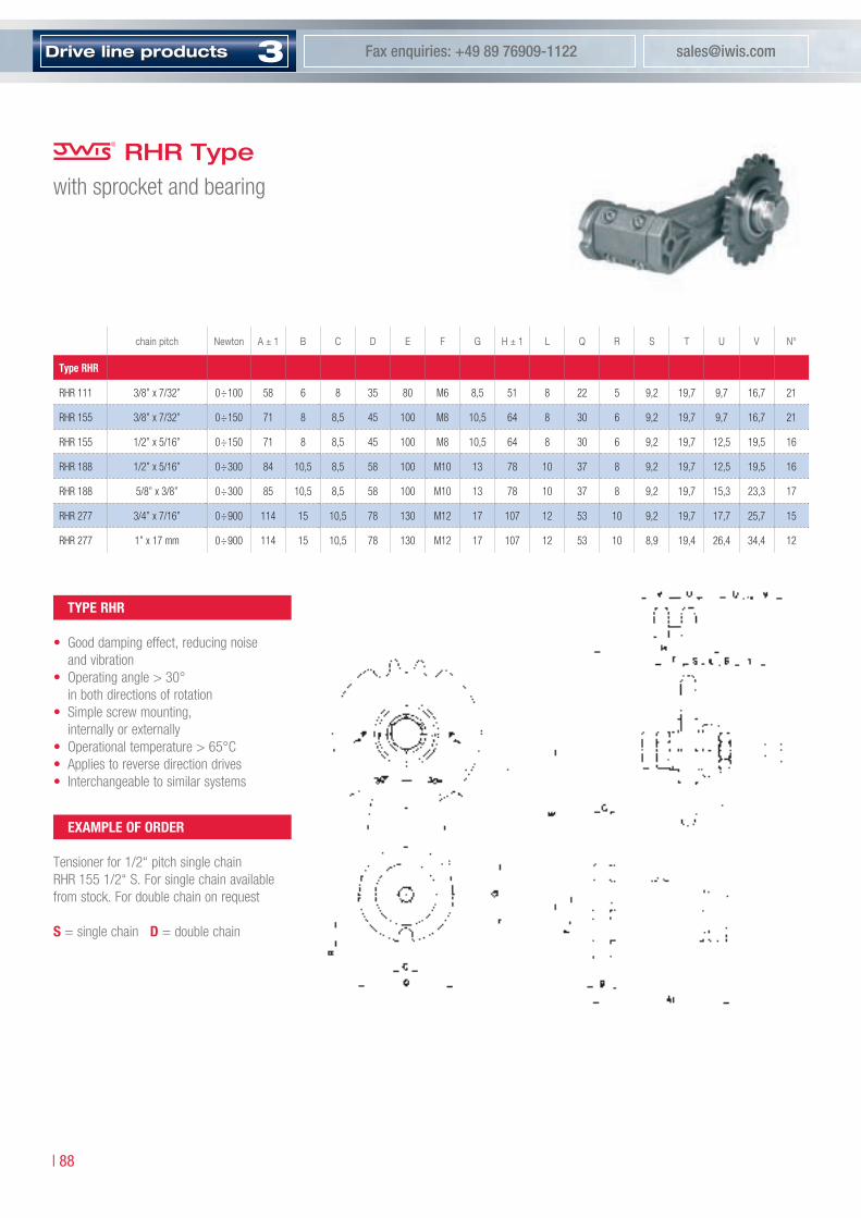
3Drive line products [email protected] enquiries: +49 89 76909-1122
| 88
RHR Typewith sprocket and bearing
chainpitch Newton A±1 B C D E F G H±1 L Q R S T U V N°
Type rhr
RHR 111 3/8” x 7/32” 0÷100 58 6 8 35 80 M6 8,5 51 8 22 5 9,2 19,7 9,7 16,7 21
RHR 155 3/8” x 7/32” 0÷150 71 8 8,5 45 100 M8 10,5 64 8 30 6 9,2 19,7 9,7 16,7 21
RHR 155 1/2” x 5/16” 0÷150 71 8 8,5 45 100 M8 10,5 64 8 30 6 9,2 19,7 12,5 19,5 16
RHR 188 1/2” x 5/16” 0÷300 84 10,5 8,5 58 100 M10 13 78 10 37 8 9,2 19,7 12,5 19,5 16
RHR 188 5/8” x 3/8” 0÷300 85 10,5 8,5 58 100 M10 13 78 10 37 8 9,2 19,7 15,3 23,3 17
RHR 277 3/4” x 7/16” 0÷900 114 15 10,5 78 130 M12 17 107 12 53 10 9,2 19,7 17,7 25,7 15
RHR 277 1” x 17 mm 0÷900 114 15 10,5 78 130 M12 17 107 12 53 10 8,9 19,4 26,4 34,4 12
Type rhr
• Good damping effect, reducing noise and vibration
• Operating angle > 30° in both directions of rotation
• Simple screw mounting, internally or externally
• Operational temperature > 65°C• Applies to reverse direction drives• Interchangeable to similar systems
exAmple oF orDer
Tensioner for 1/2“ pitch single chainRHR 155 1/2“ S. For single chain available from stock. For double chain on request
S = single chain D = double chain

Aut
omat
ict
ensi
oner
s
Telephone enquiries: +49 89 76909-1600 www.iwis.com
89 |
3
RHP Typewith low friction coefficent polythene head
chainpitch Newton A±1 B C D E F G H±1 L M N O R S T U V Z
Type rhp
RHP 111 3/8” x 7/32” 0÷100 57 6 8 35 80 M6 8,5 51 8 20 7 22 5 4 70 20 25 102
RHP 155 3/8” x 7/32” 0÷150 70 8 8,5 45 100 M8 10,5 64 8 20 7 30 6 4 70 20 25 122
RHP 155 1/2” x 5/16” 0÷150 70 8 8,5 45 100 M8 10,5 64 8 20 7 30 6 4 70 20 35 122
RHP 188 1/2” x 5/16” 0÷300 84 10,5 8,5 58 100 M10 13 78 10 20 7 37 8 4 70 20 35 122
RHP 188 5/8” x 3/8” 0÷300 85 10,5 8,5 58 100 M10 13 78 10 22 8 37 8 5 90 25 41,5 129
RHP 277 3/4” x 7/16” 0÷900 114 15 10,5 78 130 M12 17 107 12 22 8 53 10 5 90 30 49 159
RHP 277 1” x 17 mm 0÷900 114 15 10,5 78 130 M12 17 107 12 25 8 53 10 5 110 45 78 165
exAmple oF orDer
Tensioner for 1/2“ pitch single chain RHP 155 1/2“ S. For single chain available from stock. For double chain on request.
S = single chain D = double chain
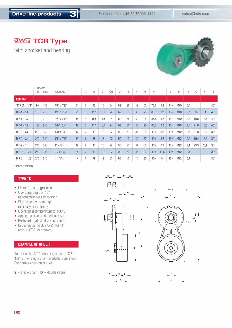
3Drive line products [email protected] enquiries: +49 89 76909-1122
| 90
TCR Typewith spocket and bearing
min. max. chainpitch N° A B C CH D E F G H I L M N O P ß
Type TCr
*TCR-05 – 3/8” 80 160 3/8” x 7/32” 21 5 15 15 24 63 35 23 23 75,5 9,2 119 M10 19,7 - - 45°
TCR-1 – 3/8” 100 210 3/8” x 7/32” 21 5 15,5 15,5 24 69 36 30 25 86,5 9,2 134 M10 19,7 18 11 45°
TCR-1 – 1/2” 100 210 1/2” x 5/16” 16 5 15,5 15,5 24 69 36 30 25 86,5 9,2 134 M10 19,7 16,5 12,5 45°
TCR-1 – 5/8” 120 240 5/8” x 3/8” 17 5 15,5 15,5 24 69 36 30 25 86,5 9,2 134 M10 19,7 21,8 15,3 45°
TCR-2 – 5/8” 200 350 5/8” x 3/8” 17 7 18 18 27 90 43 34 30 100 9,2 159 M12 19,7 21,8 15,3 30°
TCR-2 – 3/4” 200 350 3/4” x 7/16” 15 7 18 18 27 90 43 34 30 100 9,2 159 M12 19,7 19,4 17,7 30°
TCR-2 – 1” 240 380 1” x 17 mm 12 7 18 18 27 90 43 34 30 100 8,9 159 M12 19,4 23,9 26,4 30°
TCR-2 – 1 1/4” 240 380 1 1/4” x 3/4” 9 7 18 18 27 90 43 34 30 100 11,5 159 M12 19,4 - - 30°
TCR-2 – 1 1/2” 240 380 1 1/2” x 1” 9 7 18 18 27 90 43 34 30 100 14 159 M12 19,4 - - 30°
Newton
Type TC
• Linear force progression• Operating angle > 45°
in both directions of rotation• Simple screw mounting,
internally or externally• Operational temperature to 100°C• Applies to reverse direction drives• Resistant against oil and solvents• better fastening due to 2 (TCR-1)
resp. 3 (TCR-2) grooves
exAmple oF orDer
Tensioner for 1/2“ pitch single chain TCP 1 1/2“ S. For single chain available from stock. For double chain on request.
S = single chain D = double chain
* Plastic version

Aut
omat
ict
ensi
oner
s
Telephone enquiries: +49 89 76909-1600 www.iwis.com
9� |
3
TCP Typewith low friction coefficent polythene head
Tensioner for 1/2“ pitch single chain TCP 1 – 1/2“ S. For single chain available from stock. For double chain on request.
S = single chain D = double chain
min. max. chainpitch A B C CH D E F G H I L M N O P Q ß
Typ TCp
TCP-05 – 3/8” 80 160 3/8” x 7/32” 5 15 15 24 63 35 23 23 75,5 5,5 119 M10 70 20 22 45°
TCP-1 – 3/8” 100 210 3/8” x 7/32” 5 15,5 15,5 24 69 36 30 25 86,5 7 134 M10 70 20 20 22 45°
TCP-1 – 1/2” 100 210 1/2” x 5/16” 5 15,5 15,5 24 69 36 30 25 86,5 7 134 M10 70 20 20 22 45°
TCP-1 – 5/8” 120 240 5/8” x 3/8” 5 15,5 15,5 24 69 36 30 25 86,5 7 134 M10 90 22 25 29 45°
TCP-2 – 5/8” 200 350 5/8” x 3/8” 7 18 18 27 90 43 34 30 100 8 159 M12 90 22 25 29 30°
TCP-2 – 3/4” 200 350 3/4” x 7/16” 7 18 18 27 90 43 34 30 100 8 159 M12 90 22 30 29 30°
TCP-2 – 1” 240 380 1” x 17 mm 7 18 18 27 90 43 34 30 100 8 159 M12 110 25 45 35 30°
Newton
exAmple oF orDer
assembly instruction tensioner TC type page 97
noTe

3Drive line products [email protected] enquiries: +49 89 76909-1122
| 9�
TO SeriesAutomatic chain tensioners
* Plastic version
min. max. chainpitch A1 A2 A3 B C D E F G H I L M N O P R
Type To
TO-1 – 3/8” 130 250 3/8” x 7/32” 20 20 25 23 12,5 11 56,2 7 58 74 110 138 - - - 70 100
TO-1 – 1/2” 130 250 1/2” x 5/16” 20 20 25 23 12,5 11 56,2 7 58 74 110 138 - - - 70 100
TO-1 – 5/8” 130 250 5/8” x 3/8” 20 25 41,5 23 12,5 11 56,2 7 58 74 110 138 - - - 70 100
TO-2 – 5/8” 180 420 5/8” x 3/8” 22 25 41,5 28 15 12,5 70,5 9 70 87 133 169 - - - 90 120
TO-2 – 3/4” 180 420 3/4” x 7/16” 22 30 49 28 15 12,5 70,5 9 70 87 133 169 - - - 90 120
TO-3 – 1” 300 650 1” x 17 mm 25 45 78 33 17,5 14,5 82 9 86 104 160 202 21 35 70 110 140
TO-3 – 1 1/4” 300 650 1 1/4” x 3/4” 25 54 90 33 17,5 14,5 82 9 86 104 160 202 21 35 70 110 140
TO-3 – 1 1/2” 300 650 1 1/2” x 1” 25 71 119 33 17,5 14,5 82 9 86 104 160 202 21 35 70 110 140
TO-05 – 3/8” 95 190 3/8” x 7/32” 20 - - 25 12,5 9 60 10 53 75 120 149 22 48 1,5 70 100
TO-05-DP1 – 3/8” 95 190 3/8” x 7/32” 20 20 - 25 12,5 9 60 10 53 75 111 139 22 48 1,5 70 100
TO-05-DP1 – 1/2” 95 190 1/2” x 5/16” 20 20 - 25 12,5 9 60 10 53 75 111 139 22 48 1,5 70 100
TO-05-DP1 – 5/8” 95 190 5/8” x 3/8” 20 25 - 25 12,5 9 60 10 53 75 111 139 22 48 1,5 70 100
Newton
AuTomATiC ChAin TenSionerS
The automatic tensioners take up the chain slackening and keep the tension constant, without any operator attending the adjust-ment. The TO-AT-ET tighteners are designed to last and are made of top quality materials. The maximum operating temperature is 65°C (100°C for the ET model only).
Available on request:1. Studs and spring in stainless steel AISI
304 for the Food industry2. Special head shapes3. Version TO-05 and TO-05 DP1 with basic
body in plastic execution (DELRIN). Slight type with lower tensioning force – available on request.

Aut
omat
ict
ensi
oner
s
Telephone enquiries: +49 89 76909-1600 www.iwis.com
9� |
3
TA Series
min. max. chainpitch A1 A2 A3 B C D E F G H I L M N O P R
Type TA
TA-1 – 3/8” 130 250 3/8” x 7/32” 20 20 25 23 12,5 11 56,2 7 58 74 115 143 140 120
TA-1 – 1/2” 130 250 1/2” x 5/16” 20 20 35 23 12,5 11 56,2 7 58 74 115 143 140 120
TA-2 – 5/8” 180 420 5/8” x 3/8” 22 25 41,5 28 15 12,5 70,5 9 70 87 128 164 140 140
TA-2 – 3/4” 180 420 3/4” x 7/16” 22 30 49 28 15 12,5 70,5 9 70 87 128 164 140 140
TA-3 – 1” 300 650 1” x 17 mm 25 45 78 33 17,5 14,5 82 9 86 104 145 187 21 35 70 140 160
TA-3 – 1 1/4” 300 650 1 1/4” x 3/4” 25 54 90 33 17,5 14,5 82 9 86 104 145 187 21 35 70 140 160
TA-3 – 1 1/2” 300 650 1 1/2” x 1” 25 71 119 33 17,5 14,5 82 9 86 104 145 187 21 35 70 140 160
TA-3 – 1 3/4” 300 650 1 3/4” x 31 mm 29,5 - - 33 17,5 14,5 82 9 86 104 145 187 21 35 70 140 160
Tensioner for 1/2“ pitch double chain TA 1 – 1/2“ D
S = single chain D = double chain T = triple chain
Newton
exAmple oF orDer
TA SerieS
• Tensioning head made of low friction coefficient special wearproof plastic (dyna-mic friction coefficient 0.06 on dry steel)
• High tensile steel ground studs• Self-lubricating bearings for axial slide
N.B.: Our tensioners are supplied for chains complying to ISO standards.

3Drive line products [email protected] enquiries: +49 89 76909-1122
| 9�
ETR Serieswith sprocket and bearing
min. max. chainpitch Z A B C D E F G H I L M N O P Q R S
Type eTr
ETR1 – 3/8” 130 250 3/8” x 7/32” 21 20 23 12,5 11 56,2 7 58 74 99 127 - - - 11 19,7 9,2 18
ETR1 – 1/2” 130 250 1/2” x 5/16” 16 20 23 12,5 11 56,2 7 58 74 99 127 - - - 12,5 19,7 9,2 16,5
ETR2 – 5/8” 180 420 5/8” x 3/8” 17 25 28 15 12,5 70,5 9 70 87 127 163 - - - 15,3 19,7 9,2 21,8
ETR2 – 3/4” 180 420 3/4” x 7/16” 15 25 28 15 12,5 70,5 9 70 87 127 163 - - - 17,7 19,7 9,2 19,4
ETR3 – 1” 300 650 1” x 17 mm 12 30 33 17,5 14,5 82 9 86 104 151 193 21 35 70 26,4 19,4 8,9 26,4
ETR3 – 1 1/4” 300 650 1 1/4” x 3/4“ 9 30 33 17,5 14,5 82 9 86 104 151 193 - - - 29,7 19,4 11,5 37,5
Newton
eTr SerieS
• Maintenance free• Tensioning force changeable (option)• Resistant against oil and solvents• Simply mounting and adjustment• Applies to reverse direction drives

Aut
omat
ict
ensi
oner
s
Telephone enquiries: +49 89 76909-1600 www.iwis.com
9� |
3
TF SeriesPlastic tightening head
chainpitch A B C D E F G H I L N R A1 A2 A3
Type TF
TF 1 3/8” 69 35 138 10 73 10,5 40 10 15 30 15 15 20 20
TF 1 1/2” 69 35 138 10 73 10,5 40 10 15 30 15 15,25 20 20,5
TF 2 5/8” 89 45 164 12 85 12,5 50 12 18 36 18 19,5 22 25
TF 2 3/4” 89 45 164 12 85 12,5 50 12 18 36 18 21,75 22 29,5
TF 3 1” 109 55 173 13 82 12,5 60 14 20 40 20 30,5 25 46
TF 3 1 1/4” 109 55 173 13 82 12,5 60 14 20 40 20 - 25 -
TF 3 1 1/2” 109 55 173 13 82 12,5 60 14 20 40 20 - 25 -
Tensioner for 1/2“ pitch double chain TF 1 – 1/2“ D
S = single chain D = double chain T = triple chain
exAmple oF orDer
TF Type
• Wear resistant tensioning head in low friction (µ = 0.06) plastic
• Simple mounting and adjustment• Operational temperature to 65°C
Our tensioners are supplied for chains complying to ISO standards.
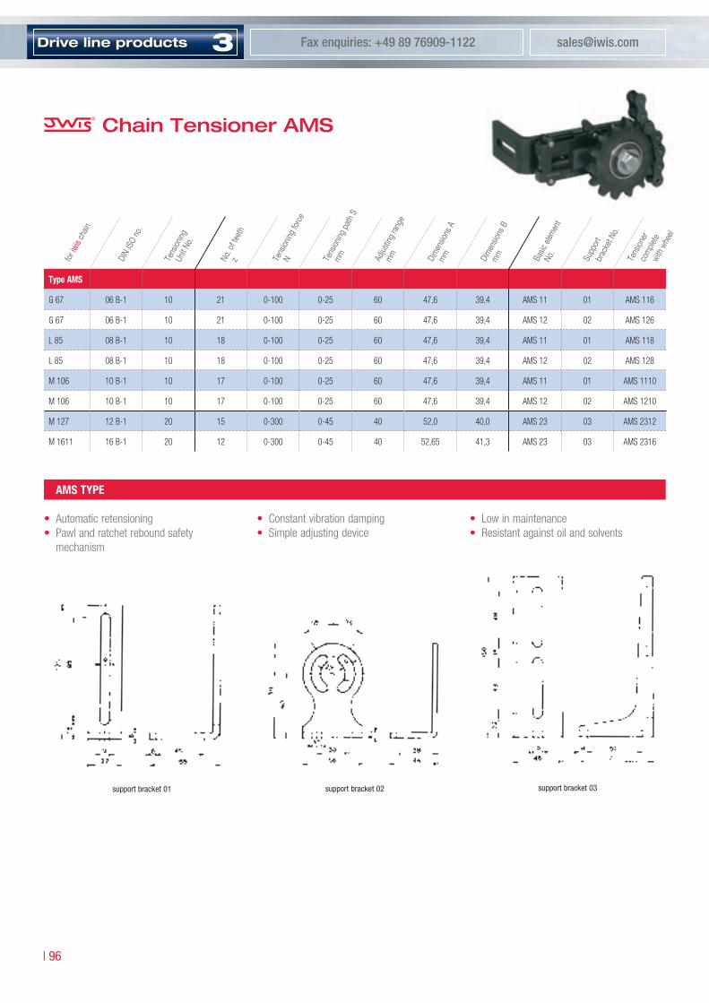
3Drive line products [email protected] enquiries: +49 89 76909-1122
| 96
Chain Tensioner AMS
Type AmS
G 67 06 B-1 10 21 0-100 0-25 60 47,6 39,4 AMS 11 01 AMS 116
G 67 06 B-1 10 21 0-100 0-25 60 47,6 39,4 AMS 12 02 AMS 126
L 85 08 B-1 10 18 0-100 0-25 60 47,6 39,4 AMS 11 01 AMS 118
L 85 08 B-1 10 18 0-100 0-25 60 47,6 39,4 AMS 12 02 AMS 128
M 106 10 B-1 10 17 0-100 0-25 60 47,6 39,4 AMS 11 01 AMS 1110
M 106 10 B-1 10 17 0-100 0-25 60 47,6 39,4 AMS 12 02 AMS 1210
M 127 12 B-1 20 15 0-300 0-45 40 52,0 40,0 AMS 23 03 AMS 2312
M 1611 16 B-1 20 12 0-300 0-45 40 52,65 41,3 AMS 23 03 AMS 2316
support bracket 0� support bracket 0�
AmS Type
• Automatic retensioning• Pawl and ratchet rebound safety mechanism
support bracket 0�
fori
wisc
hain
DIN
ISO
no.
Tens
ioning
Unit
No.
No.o
ftee
thz Te
nsion
ingfo
rce
N Tens
ioning
pat
hS
mm Adjus
ting
rang
em
m Dim
ensio
nsA
mm Dim
ensio
nsB
mm Basic
elem
ent
No.
Supp
ort
brac
ketN
o.
Tens
ioner
co
mple
te
with
whe
el
• Constant vibration damping• Simple adjusting device
• Low in maintenance• Resistant against oil and solvents

Aut
omat
ict
ensi
oner
s
Telephone enquiries: +49 89 76909-1600 www.iwis.com
9� |
3
AmS 10 AmS 20
Base Tensioner
BaseTensioner
Chain Tensioner AMS
TC TypeTensioner assembly TC Type
CorreCT ASSemBly wrong ASSemBly AlTernATive A AlTernATive B
Telephone enquiries: +49 89 76909-1600 www.iwis.com
99 |
4
Regular maintenance and lubrication are preconditions for low wear and long service life of the chain drive. The maintenance and lubrication frequency, as well as the rela-ted re-lubrication, are determined by the operating conditions of the application. The iwis chain guide outlines the choice of possible chain lubrications and recommended re-lubricants. All initial lubricants are developed especially for iwis and their compositi-on is tailored to be the best possible for the product chain. Please contact our Technical Service Team for more information regarding the maintenance and handling of chains. We will happily advise you!
Chain guide
99 |
4
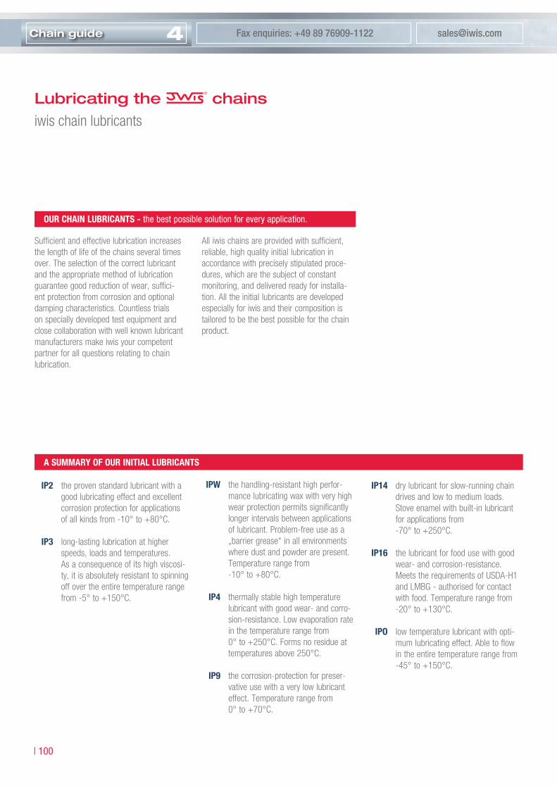
4Chain guide [email protected] enquiries: +49 89 76909-1122
| �00
Lubricating the chainsiwis chain lubricants
Sufficient and effective lubrication increases the length of life of the chains several times over. The selection of the correct lubricant and the appropriate method of lubrication guarantee good reduction of wear, suffici-ent protection from corrosion and optional damping characteristics. Countless trials on specially developed test equipment and close collaboration with well known lubricant manufacturers make iwis your competent partner for all questions relating to chain lubrication.
All iwis chains are provided with sufficient, reliable, high quality initial lubrication in accordance with precisely stipulated proce- dures, which are the subject of constant monitoring, and delivered ready for installa-tion. All the initial lubricants are developed especially for iwis and their composition is tailored to be the best possible for the chain product.
ip2 the proven standard lubricant with a good lubricating effect and excellent corrosion protection for applications of all kinds from -10° to +80°C.
ip3 long-lasting lubrication at higher speeds, loads and temperatures. As a consequence of its high viscosi-ty, it is absolutely resistant to spinning off over the entire temperature range from -5° to +150°C.
ip14 dry lubricant for slow-running chain drives and low to medium loads. Stove enamel with built-in lubricant for applications from -70° to +250°C.
ip16 the lubricant for food use with good wear- and corrosion-resistance. Meets the requirements of USDA-H1 and LMBG - authorised for contact with food. Temperature range from -20° to +130°C.
ipo low temperature lubricant with opti-mum lubricating effect. Able to flow in the entire temperature range from -45° to +150°C.
ipw the handling-resistant high perfor-mance lubricating wax with very high wear protection permits significantly longer intervals between applications of lubricant. Problem-free use as a „barrier grease“ in all environments where dust and powder are present. Temperature range from -10° to +80°C.
ip4 thermally stable high temperature lubricant with good wear- and corro-sion-resistance. Low evaporation rate in the temperature range from 0° to +250°C. Forms no residue at temperatures above 250°C.
ip9 the corrosion-protection for preser-vative use with a very low lubricant effect. Temperature range from 0° to +70°C.
A SummAry oF our iniTiAl luBriCAnTS
our ChAin luBriCAnTS - the best possible solution for every application.

Cha
ing
uid
e
Telephone enquiries: +49 89 76909-1600 www.iwis.com
�0� |
4
operating timeChai
n el
onga
tion
in %
admissible chain elongation
ip9 iwis VP6-Kombi superplus (spray) All conventional chain oils
ip14 iwis VP6-Kombi superplus (spray) Chain oils containing a proportion of solid lubricant such as graphite, MOS2
ip16 chain oils approved for food use, e.g. Klüberoil UH 1-series
ipo low temperature chain oils from various manufacturers
ip2 iwis VP6 Kombi superplus (spray) All standard commercial chain oils
ip3 iwis VP6 Kombi superplus (spray) High performance chain oils from various manufacturers, e.g. STRUCTOVIS HD-series from Klüber Lubrication
ipw iwis VP6-Kombi superplus (spray) High performance chain oils from various manufacturers, e.g. STRUCTOVIS HD-series from Klüber Lubrication
ip4 iwis VP6-Kombi superplus (spray) High temperature chain oils from various manufacturers, for temperatu-res above 250°C with proportions of solid lubricant
Designation initial lubricantRecommendation re-lubricant
Re-lubrication of the chainsRe-lubricants
reCommenDeD re-luBriCAnTS For our iniTiAl luBriCAnTS
Dry running:Chain without initial and top-uplubrication
re-luBriCATion
The life of a chain is dependent to a decisive extent on correct and adequate topping up of the lubricant. As a consequence of the oscil-lating movements of the chain link, the initial lubricant is used up in the course of time depending on the operating conditions.If the lubricant is topped up regularly, the chain is mainly within the range of fluid and mixed friction. An absence of lubricant or badly selected re-lubricants cause dry friction, which leads to the formation of fretting corro-sion and increased wear on the chain.
The selection of the lubricant and the correct lubrication technique is decisive for effective top-up lubrication.
Initial lubrication without top-up
Top-up interval too long:occasional dry-running
Incorrect top-up Optimum re-lubrication
re-luBriCAnTS
should possess the following characteristics - depending on the application:
• Adhesiveness• Compatibility with initial lubricant• Corrosion protection• Load-bearing capacity of lubricant film• Ability to creep• Lubrication of emergency running• High viscosity and simultaneous
ability to flow• High temperature stability• Water-repellent• Resistance to media etc.
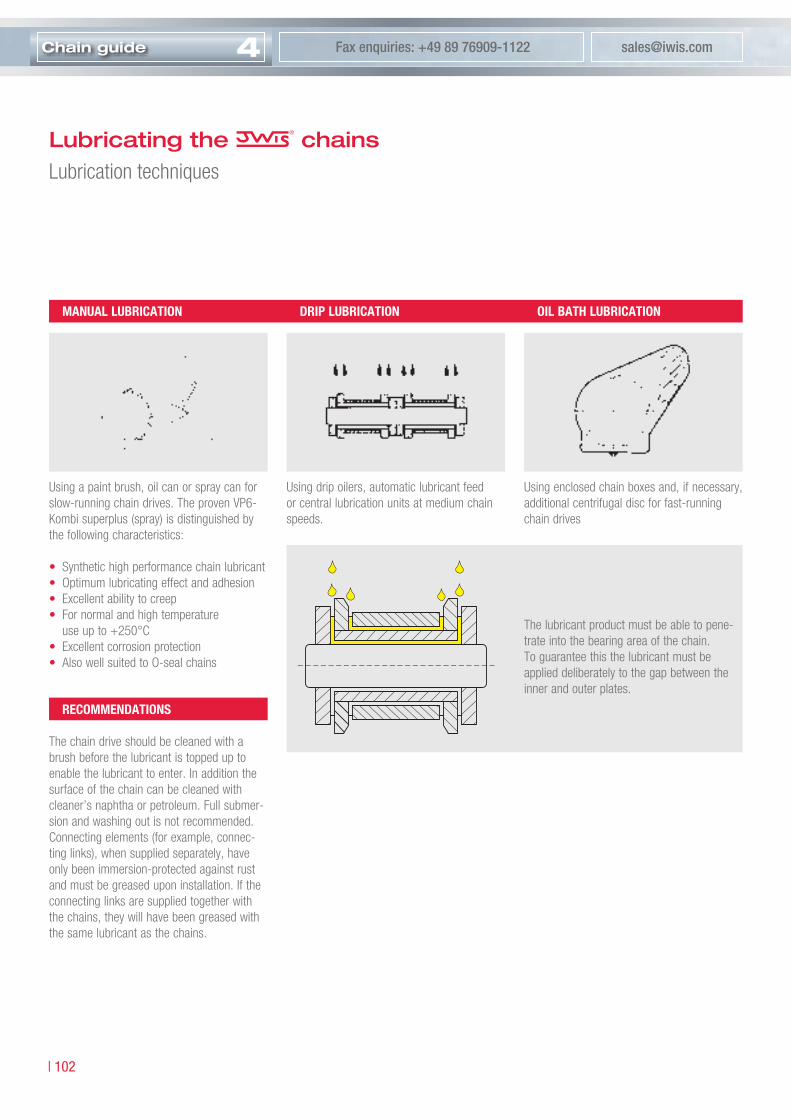
4Chain guide [email protected] enquiries: +49 89 76909-1122
| �0�
mAnuAl luBriCATion
Using a paint brush, oil can or spray can for slow-running chain drives. The proven VP6-Kombi superplus (spray) is distinguished by the following characteristics:
• Synthetic high performance chain lubricant• Optimum lubricating effect and adhesion• Excellent ability to creep• For normal and high temperature
use up to +250°C• Excellent corrosion protection• Also well suited to O-seal chains
Drip luBriCATion
Using drip oilers, automatic lubricant feed or central lubrication units at medium chain speeds.
oil BATh luBriCATion
Using enclosed chain boxes and, if necessary, additional centrifugal disc for fast-running chain drives
reCommenDATionS
The chain drive should be cleaned with a brush before the lubricant is topped up to enable the lubricant to enter. In addition the surface of the chain can be cleaned with cleaner’s naphtha or petroleum. Full submer-sion and washing out is not recommended.Connecting elements (for example, connec-ting links), when supplied separately, have only been immersion-protected against rust and must be greased upon installation. If the connecting links are supplied together with the chains, they will have been greased with the same lubricant as the chains.
The lubricant product must be able to pene-trate into the bearing area of the chain.To guarantee this the lubricant must be applied deliberately to the gap between the inner and outer plates.
Lubricating the chainsLubrication techniques

Cha
ing
uid
e
Telephone enquiries: +49 89 76909-1600 www.iwis.com
�0� |
4
Efficient chain maintenance
Regular maintenance and lubrication are pre-conditions for low wear and long service life of the chain drive. Maintenance and lubricati-on frequency, as well as the related re-lubri-cation, ist determined by operating conditions (tensile forces, temperature, contamination, aggressive media).
mAinTenAnCe
During regular visual inspections special attention should be paid to stretching due to wear, tension, lubrication condition, and evidence of wear due to tracking errors.
Checking the maximum permissible stretching due to wear:
The length of a chain is defined by the pitch p and the number of links X. In the course of time stretching due to wear occurs, and usually this can be measured without remo-ving the chain. The difference from precise measurement with a specified measurement load is slight if measurements are conducted over the highest possible number of chain links, approximately 20 to 40.
The chain should be replaced at:• max. 3 % for simple drives• max. 2 % for high-performance drives• max. 1 % for special applications
(synchronous operation, positioning)
Controlled retensioning of the chains has a very positive effect on the chain life. Extreme retensioning should be avoided just as much as excessive slack. A guideline figure would be a tension load of approx. 5 % of the actual chain pulling force. In the case of chains running in parallel both strands must be tensioned equally, at best by a common shaft for both sprockets. If no automatic chain ten-sioning device is available, the chain must be adjusted by hand by altering the distance bet-ween the sprocket shafts. A further possibility with long drives is to shorten the chain by removing individual links, provided that wear is relatively light. Various tools are available for dismantling and reassembling the chain. These tools are available for parallel pin and shouldered pin chains.
Before re-lubrication the chains and sprok-kets should be cleaned to remove obstinate contamination and to permit the lubricant to penetrate via the back of the plates. The sur-face of the chain can also be cleaned using an appropriate solvent. Complete immersion and washing is not recommendet as the
cleaning agent does not evaporate completely from within the chain and thus the penetrati-on of the fresh lubricant is obstructed.
During visual inspection attention should be paid to evidence of chain linkplate marking and wear due to tracking errors. These are caused by misaligned sprockets or guides or by chains which are not in parallel.
Guide for alignment deviations per 100 mm axle separation:• 0.1 mm with fast-running drives
and close axle spacing;• 0.2 mm with slow-running drives.
The sprockets should be constantly inspected and if necessary replaced. We do not recom-mend that new chains are used with worn sprockets.
meASuremenT oF STreTChing Due To weAr
Pitch p · number of links C
Measured length Lm
Stretching due
to wear ∆ L

4Chain guide [email protected] enquiries: +49 89 76909-1122
| �0�
yes
no
Standard application
Parallel running
Damp / corrosive environment
Dusty environment
Free of grease environment
High loads
High temperature environment
Hygienic environment
Std. roller and conveyor chainsSL chains 1)
CR corrosion resistant chains 1)
MEGAlife maintenance free chains 1)
Nickel-plated chains 1)
Std. roller and conveyor chainsSL chainsCR corrosion resistant chainsMEGAlife maintenance free chainsNickel-plated chains
reduced DIN length tolerances
chain guidelineWhich application demands which chain type?
yes
no
Nickel-plated chains with initial lubrication
CR corrosion resistant chains with initial lubrication
MEGAlife maintenance free chains with initial lubrication
Chains with IPW-lubrication
MEGAlife maintenance free chains
SL chainsNickel-plated chains
MEGAlife maintenance free chains 2)
SL chains 3)
CR corrosion resistant chains 3)
MEGAlife maintenance free chains 3)
Nickel-plated chains 3)
SL chains 4)
CR corrosion resistant chains 4)
Nickel-plated chains 4)
Chains with special lubrication 4)
CR corrosion resistant chainsNickel-plated chains
MEGAlife maintenance free chainsNickel-plated chains
SL roller and conveyor chains
High loads?
Medium loads / corrosive
Lubrication allowed?
yes
no
yes
no
yes
no
yes
noLubrication allowed?
yes
no 80°C
yes
nocorrosive surrounding?
�) a
pplic
atio
n lim
ited
�) w
ith s
tand
ard
lubr
icat
ion
or IP
W �)
IP u
p to
��0
°C a
nd IP
� up
to �
�0°C
�) w
ith re
duce
d to
lera
nces
MEGAlife IChain velocity 3 m/s
yes
no MEGAlife II
Cha
ing
uid
e
Telephone enquiries: +49 89 76909-1600 www.iwis.com
�0� |
4
chain guidelineImportant information and notes
The following guidelines support you in choosing the right chain. However, please note that each application is individual. The result should in no case serve as a basis for your order. Therefore please refer to our professional employees who are happy to submit an individual order to you. We do not assume any guarantee or liability.
• SL chains Page 14 and 20
• Nickel-plated chains Page 14
• MEGAlife maintenance free chains Page 32
• CR corrosion resistant chains Page 42
ChAin FABriCATion lengThS
• 5 m• 10 m• 10 Fuß
Adjusted lengths can either be supplied open or closed. Special lengths (e.g. on coils) are available on request and depending on chain type.
priCe SupplemenTS:
Price supplements will be calculated for:• adjusted lengths• special lubrications• reduced tolerances• short lengths• special coatings• nickel-plated chains and single partsPrices on enquiry.
CuSTom-mADe ChAinS
Special chains made according to customer drawings are possible. Prices on enquiry. Minimum order quantity is 50 m.
our Conveyor ChAinS
If a parallel run is necessary, iwis can manufacture and supply chain strands with precisely harmonised lengths, bundled together and marked accordingly. This is in particular important for chains with opposite cam or angle side plates.
Chaindimensions Innerlink/Outerlink/Connectinglink CotteredLink
6 mm – 3/4“ 20 ea 10 ea
1“ – 1 1/4“ 10 ea 10 ea
Duplex – Triplex 5 ea 5 ea
Parts over 1 1/4“ 1 ea 1 ea
minimum orDer quAnTiTieS For ConneCTorS AnD CrAnkeD linkS
imporTAnT DeTAil For more inFormATion To
ChAin engineering progrAm
iwis provides you with a special PC-Software serving as support for the specification of the individual chain drive design or rather the preselection of the appropriate chain. Please ask our Customer Service Team!
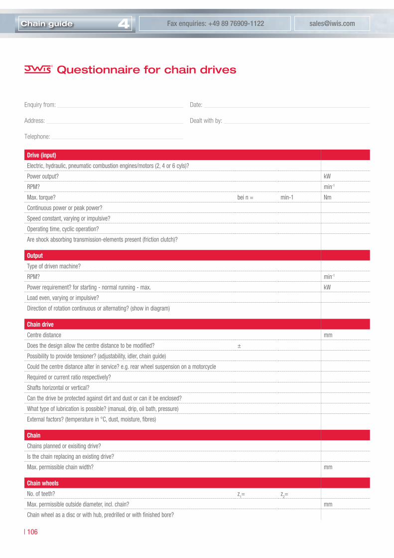
4Chain guide [email protected] enquiries: +49 89 76909-1122
| �06
Questionnaire for chain drives
Drive (input)
Electric, hydraulic, pneumatic combustion engines/motors (�, � or 6 cyls)?
Power output? kW
RPM? min-�
Max. torque? bei n = min-� Nm
Continuous power or peak power?
Speed constant, varying or impulsive?
Operating time, cyclic operation?
Are shock absorbing transmission-elements present (friction clutch)?
output
Type of driven machine?
RPM? min-�
Power requirement? for starting - normal running - max. kW
Load even, varying or impulsive?
Direction of rotation continuous or alternating? (show in diagram)
Chain drive
Centre distance mm
Does the design allow the centre distance to be modified? ±
Possibility to provide tensioner? (adjustability, idler, chain guide)
Could the centre distance alter in service? e.g. rear wheel suspension on a motorcycle
Required or current ratio respectively?
Shafts horizontal or vertical?
Can the drive be protected against dirt and dust or can it be enclosed?
What type of lubrication is possible? (manual, drip, oil bath, pressure)
External factors? (temperature in °C, dust, moisture, fibres)
Chain
Chains planned or exisiting drive?
Is the chain replacing an existing drive?
Max. permissible chain width? mm
Chain wheels
No. of teeth? z�= z�=
Max. permissible outside diameter, incl. chain? mm
Chain wheel as a disc or with hub, predrilled or with finished bore?
Enquiry from: Date:
Address: Dealt with by:
Telephone:

Cha
ing
uid
e
Telephone enquiries: +49 89 76909-1600 www.iwis.com
�0� |
4Example used:Drive running in clockwise direction, in inclined arrangement, speed reducing ration
The relevant dimensions with permissible tolerances should be entered in the diagram below.
Questionnaire for chain drives

partners worldwide
| �08

Content-navigator
Our Company:
Product range:
Drive line products:
Chain guide:
14 Roller chains
20 Conveyor chains
32 MEGAlife chains
42 CR chains
46 Power and free conveyor chains
58 Special chains
70 Sprockets and plate wheels
74 Tools
86 Automatic Tensioners
1 iwis antriebssysteme
100 Perfect lubrication
103 Efficent chain maintenance
104 Chain guideline
106 Questionnaire for chain drives
108 Partners worldwide
Partners worldwide www.iwis.com
SpainPermarin S.A.Poligono Industrial Fuente del JarroC/Ciudad de Sevilla, 1046988 Paterna - ValenciaTel. +34-96-1368000Fax [email protected]
SpainIrati Business S.L.Aptdo.Correos Nr. 2108470 Sant CeloniTel. +34-93-8484048Fax [email protected]
SwitzerlandIWIS AG KettentechnikBahnweg 4 (Postfach 23)5504 OthmarsingenTel. +41-62 8898999Fax +41-62 [email protected]
SwedenBengtssons Maskin A.B.Raseborgsgatan 7 - 9P.O. Box 607216406 Kista (Stockholm)Tel. +46-8-7030270Fax +46-8-7514142info.transmission@bengtssons-maskin.sewww.bengtssons-maskin.se
PolandEnitra sp. zo.o. (GmbH)ul. 1 Maja 6258-300 WalbrzychTel. +48 748439124Fax +48 [email protected]
DenmarkRekord Teknik & Transmission A/SVallensbaekvej 462625 VallensbaekTel. +45-43660999Fax [email protected]
Braziliwis Ketten Correntes do Brasil Ltda.Rua Ella Muhlemann, 200Bairro Ressaca06850.000 Itapecericada Serra -, SPTel. 0055-11-46663927Fax [email protected]
BelgiumS.A. Vermeire Belting N.V.Rue de la Filature, 414800 EnsivalTel. +32-87-322360Fax [email protected]
ArgentinaCasa Mariscal S.A.I.C.Av. Juan B. Alberdi 2371424 Buenos AiresTel. +54-11-49010999Fax [email protected]
AustriaIng. Franz Henzinger GmbHIndustrievertretungIgnaz-Mayer-Str. 44020 LinzTel. +43-732-7745800Fax [email protected]
PortugalJuncor Acessorios Ind. e Agricolas, Lda.Rua Antonio Silva Manrinho, 664100 063 PortoTel. +351-22 619 7360Fax +351 33 619 [email protected]
USASKF USA Inc.1530 Valley Center Parkway Suite 180Bethlehem, PA 18017Tel. +1-610-86148 00Fax +1-610-86148 11Tollfree [email protected]
HungaryBearings Co. Ltd.Gergely u. 3-91105 BudapestTel. +361 2620508Fax +361 [email protected]
TurkeyDinamik Transmisyon ZincirTicaret Ve Sanayii A.S.Kürekciler Sokak No. 48 - 5080000 Karaköy - IstanbulTel. +90-212-2450498Fax +90-212-2435434
Czech RepublicUlmer s.r.o.Generála Vlachého 30574762 Mokré LazceTel. +420-553-757111Fax [email protected]
NorwayIndustri-Fokus A/SPostboks 441 Ökern0513 OsloTel. +47-22-724554Fax [email protected]
ItalyRIMA S.p.A.Via Brunetti 1020156 MilanoTel. +39-02-33404355Fax [email protected]
HollandSpruit Transmissies B.V.Ivoorstraat 41812 RE AlkmaarTel. +31-72-5412000Fax [email protected]
FranceSKF Equipments30-32 Avenue des Trois Peuples78180 Montigny - Le BretonneuxTel. +33-1-30126963Fax +33-1-3026909www.skfequipements.skf.fr
Franceiwis France10, rue du Luxembourg69630 MeyzieuTel. +33-4 78 40 86 68Fax +33-4 78 40 86 [email protected]
FinlandM F G Components OyPajatie 182600 TohmajärviTel. +358-207322020Fax [email protected]
Englandiwis-Flexon Ltd.Unit 8c Bloomfield ParkBloomfield Road, TiptonWest Midlands, DY4 9APTel. +44-1299-400080Fax [email protected]
EURoPE
NoRTH AND SoUTH AmERICA
ASIA
ChinaOn Gear Trading Co., Ltd.5/F CCT Telecom Building11 Wo Shing StreetFotan, Hong KongTel. +852-2690 3320Fax +852-2690 [email protected]
TaiwanChun Chiang Enterprises Co., Ltd.7F, 17, Lane-49, Sec. 1Anho RoadTaipeh 106Tel. +886-2-7818460Fax +886-2-7816078
Chinaiwis Drive System (Shanghai) Co. Ltd.Room #717, German Center88 Keyuan RoadZhangjiang, PudongShanghai 201203 R.O.C.Tel: +86-21-2898 63 88Fax +86-21-2898 63 [email protected]
HollandFlexon BeneluxSlotlaan 5NL-1871 BC SchoorlTel. +31-72-50949-81Fax +31-72-50949-97
AFRICA
EgyptGaicoGeneral Automotive & Ind. Co. Ltd.10,13 Al Farik Mohamed Ibrahim Str.Abbas Al Akkad Region No. 6Zamlek, Nasr City, CairoTel. +2-2-2736265Fax [email protected]
South AfricaBearing Man Ltd.P.O. Box 25191, Gateway 43216 Tetford Circle /Millennium Bridge Business Park4320 La Lucia RidgeTel. +27 31 5766269Fax +27 31 [email protected]
AustraliaCBC Consolidated Bearing CompanyThe Crescent2208 KingsgroveTel. +61 0295021833Fax +61 [email protected]
New ZealandSAECOBearings and Transmission36 Hastie Ave.Mangere, AucklandTel. +64 9 6347540Fax +64 9 [email protected]
AUSTRAlIA
USAFlexon USA, LLCNorth and South America3902 Hanna Circle, Suite FIndianapolis, IN 46241Tel: +1-317-821-3539Fax [email protected]
©Copyright iwis antriebssysteme GmbH & Co. KG, München, Germany 2007
The contents of this catalogue are the copyright of the publisher and may not be reproduced (even extracts) unless permission is granted. Every care has been taken to ensure the accuracy of the information contained in this catalogue but no liability can be accepted for any errors or omissions.
Printed: EN, 03/2007, 3000
1Our Company
Welcome
iwis2
3
1
4
Given by:
Member of:
Get in touch with us!Our competent team of employees in the officeand on the road is pleased to offer you extensive advice.
iwis antriebssystemeGmbH & Co. KGAlbert-Roßhaupter-Straße 5381369 München GERMANYTel. +49 89 76909-1600Fax +49 89 76909-1122Internet: www.iwis.comeMail: [email protected]
Produkt range
Precision chain systems
for drive and conveyor purposes
For a better orientation in our general catalogue you can use our content-navigator on the back side of the cover. Please turn this page and find the desired page faster.
Pre
cisi
on
chai
n sy
stem
s fo
r d
rive
and
co
nvey
or
pur
po
ses