Embed Size (px)
Citation preview

IWAKIHI-TECHNO
PUMPS
IX-C

PVDFhead
Capacity: 0.2 - 150 L/h Capacity: 0.08 - 60 L/h
IX-C150TCFJ-TB-E IX-C150TCR-TB-E IX-C060TCFJ-TB-E IX-C060TCR-TB-E
1
A new generation of advanced metering pump technology!

C150 C060Capacity: 0.2 - 150 L/h Capacity: 0.08 - 60 L/h
SUShead
IX-C150S6FJ-TB-E IX-C150S6R-TB-E IX-C060S6FJ-TB-E IX-C060S6R-TB-E
2
IWAKI HI-TECHNO PUMPS IX
Highly precise control offers a solution for every chemical dosing application.Iwaki’s IX Series are digitally controlled direct-drive diaphragm pumps. Years of experience in high-end motor technology result in extremely accurate and energy efficient metering pumps with high resolution.The IX Series meet today’s demand for automated chemical delivery in industries from water treatment to chemical process.
A new generation of advanced metering pump technology!
Energy savings Degassing ability
70% 1MPaHigh accuracy
±1%Turn down ratio Max. viscosity
750:1 1000 mPa•sUPTO

Precise chemical dosing operation and energy savingsAdvanced mechanism assists eco-friendliness
3

Diaphragmrupture detector
Drain
Diaphragm
Precise chemical dosing operation and energy savingsAdvanced mechanism assists eco-friendliness
Maximum suction lift:
2mWith an open discharge line and dry valve condition.
Degassing ability:
C060: 1.0 MPa, C150: 0.4 MPaWith a standard tubing layout.
Lowpulsation
IX series General-purpose motormetering pump
T
3T 2T
T
T 2T
T
T
Constantinjection
Flowrate
100%
Flowrate50%
Discharge
Suction
Discharge
Suction
Spring back designAssist spring design
Reduced70%
Total load isalmost equal
Motor load - Assist spring+ Sliding resistance
200W
Dischargecycle
Suctioncycle
Dischargecycle
Suctioncycle
60W
Motor load + Spring load+ Sliding resistance
Suction load+ Sliding resistance
Motor load + Spring load+ Sliding resistance
C150 Capacity 0.2 - 150L/h
C060 Capacity 0.08 - 60L/h
4
IWAKI HI-TECHNO PUMPS IX
Viscous liquid transferStandard IX series is capable of pumping
liquid viscosities of up to 1000mP•a.
Contact us for higher viscosity applica-
tions.
Compliant to world standardsOne of the IX features is multi-voltage
operation (100-240VAC) compatible
worldwide. Compliant to UL, CE stan-
dards.
IP65Drive and control units are sealed sepa-
rately to an IP65 enclosure.
Safety designStandard to all models is a diaphragm
rupture detector, protecting users and the
environment. Also, a detector for abnormal
operation protects the pipework in case of
an accidental high discharge pressure
caused by clogging or improper operation.
A drain hole also ensures safe operation
even when the diaphragm is damaged.
A wide turn down ratioA control motor adjusts the discharge
and suction speeds to meet a wide
turndown ratio of 750:1.
Energy savings and Eco-friendlyWith the use of helical gears and spring
assistance, power consumption is re-
duced by 70% compared to the standard
spring back design.
Precise chemical dosingoperationThe valve design maintains precise
dosing at any flow rate whilst the motor
regulates discharge and suction speeds
to achieve high accuracy (+/-1%) all with a
cost effective design from a mechanically
driven diaphragm pump.
Efficient pump head design is incorporated with high compressionFast priming without air locks is achieved
with a high compression ratio due to a
fixed (maximum) stroke length.
Constant injection with low impactFlow control via discharge speed adjust-
ment (with a fixed suction speed) assures
constant injection at any flow rate. This
system also reduces impact (inertia force)
and load to the discharge line.
IX-C150TCR-TB-E IX-C060TCR-TB-E

5
Easy operation on aVariety of applications

6
IWAKI HI-TECHNO PUMPS IX
Automatic controlThe IX can run in analogue, pulse, batch or interval batch modes.
Interval batch operationTimed operation is possible with
simple
pump programming via the keypad
and is initiated with a pulse signal.
Analogue operationThe pump operates in response to an
input, (4-20mA) from a controller.
Pulse operationWhen combined with a flow meter or
contact head water meter, the IX pump
gives a paced dose rate in proportion
to the main flow rate.
User friendly designThe controller position can be selected
from 6 mounting positions for operator
convenience. Also, a character LCD with
LED backlight and optimized keypad
positions assist easy operation.
CalibrationThe pump is calibrated prior to shipment,
however we recommend recalibration
when installed in your system due to pipe
layout and liquid properties.
Operation historyController memory logs the total power
connection time, operating time, number
of strokes and number of power-up
events.
Maintenance modeThis operation makes it possible to move
the diaphragm forward with partial pump
stroke operation facilitating diaphragm
replacement.
Cavitation preventionWhen pumping viscous liquids, suction
stroke speed can be varied to avoid
developing cavitation.
(Programmable suction speed: 75%, 50%
or 25% of the normal speed)
DegassingKeypad operation or the contact signal
(AUX) runs the pump at maximum spm in
any mode for degassing.
Top backTB type
Top rightTR type
Right faceRF type
Top frontTF type
Left faceLF type
Top leftTL type
6 patternsControllerlocation
Capacity
Time
Pulse signal
Main ow Flowmeter
Current signal (4-20 mA)
PH controller
Specications of pump
• The max. discharge capacity is obtained in operation with clear water at ambient temperature and the max. discharge pressure. It gets higher as the pressure gets lower. • Operating temperature range: 0-50 ˚C (Indoor use only) • Operating humidity range: 0-90%RH (Non condensing in the controller) • Contact us for other plumbing connections• For the IX-C150S6, a target flow rate may not be met when it is set to 1.0 L/h or below. For the IX-C060S6, a target flow rate may not be met when it is set to 0.4 L/h or below.
Note 1: For the IX-C150S6, accuracy is not guaranteed at flows below 1.0 L/h. For the IX-C060S6, accuracy is not guaranteed at flows below 0.4 L/h.Note 2: No viscosity change, Non freezing, No slurry.
Pump identication
Drive unitC
Pump size060: 60 L/h150: 150 L/h Wet-end material
TC, TE, S6Please refer to above figure.
ConnectionR: Thread (R)N: Thread (NPT)FD: Flange (DIN)FJ: Flange (JIS)FA: Flange (ANSI)
Controller locationTB: Top backTF: Top frontTR: Top rightTL: Top leftRF: Right faceLF: Left face
Model cord control numberNo code: 060 1: 150
Special arrangement codeNo code: Standard models S: Customized models
Type of power cordE: EuropeJ: JapanU: USA (115 V)U2: USA (230 V)
IX - C 150 TC R - TB E-
Model Maximumpressure
MPa
Capacity
L/h Thread Flange kg
0.08 - 60
0.2 - 150
1.0
0.4
Powerconsumption
W
62
62
Currentdraw
A
0.8
0.8
Connection Mass
IX-C060(TC/TE)
IX-C060S6 Note1
IX-C150(TC/TE)
IX-C150S6 Note1
R: R1/2
N: 1/2NPT
R: R3/4
N: 3/4NPT
FJ: JIS10K 15A
FD: DIN PN10 DN15
FA: ANSI 150Lb 1/2”
FJ: JIS10K 20A
FD: DIN PN10 DN20
FA: ANSI 150Lb 3/4”
9
11
12
9
11
13
Maximumviscosity
mPa•s
1000
1000
Liquidtemperature
range
˚C Note 2
0 - 50
0 - 50
0 - 80
0 - 80
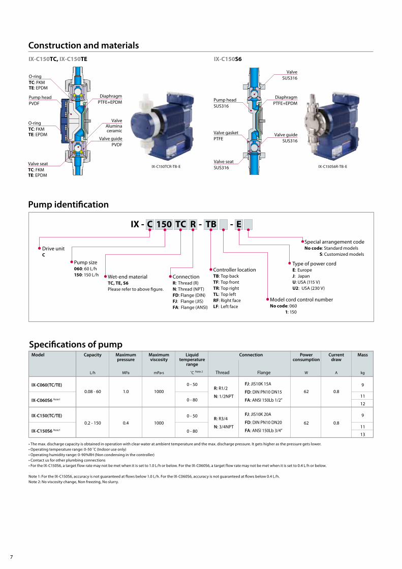
Construction and materials
Pump headPVDF
Pump headSUS316
Valve gasketPTFE
O-ringTC: FKMTE: EPDM
IX-C150TC, IX-C150TE IX-C150S6
DiaphragmPTFE+EPDM
DiaphragmPTFE+EPDM
ValveAluminaceramic
ValveSUS316
Valve guidePVDF
Valve guideSUS316
Valve seatTC: FKMTE: EPDM
Valve seatSUS316
O-ringTC: FKMTE: EPDM
IX-C150TCR-TB-E IX-C150S6R-TB-E
7

Specication of controllerMonitors
Operation Keypads
Operation mode
Control function
Input Note 2
Output
Safety function
Power voltage
LCD
LED
MAN (Manual)
EXT
STOP
PRIME
Interlock
AUX
STOP / Pre-STOP / AUX / Interlock
Analogue
Pulse
Alarm 1 Note 4
Alarm 2 Note 4
Power supply
Diaphragm rupture detection
Overpressure detection
Analogue control
Pulse control
Batch control
Interval batch control
16×2 backlight LCD
Operation / Stop / Alarm
START / STOP MENU ESC Enter
C060: 0.08 mL/h - 60 L/h, C150: 200 mL/h - 150 L/h
4 - 20, 0 - 20, 20 - 4, 20 - 0 mA
C060: 0.00625 mL/PLS - 120 mL/PLS, C150: 0.01560 mL/PLS - 300 mL/PLS
C060: 6.25 mL/PLS - 120 L/PLS, C150: 15.6 mL/PLS - 300 L/PLS Note 1
Capacity C060: 6.25 mL - 120 L, C150: 15.6 mL - 300 L Note 1
Time 0-9 day, 0-23 H, 1-59 min
Operation stop at contact input
Operation stop at contact input
Operation with max. spm at contact input
No-voltage contact or open collector
Probus Note 3Communication protocol: Probus-DP
International standard: Compliant to EN50170 (IEC61158)
0-20 mA DC (Internal resistance is 200 Ω .)
No-voltage contact or open collector (MAX pulse frequency is 100 Hz.)
No-voltage contact (Mechanical relay) 250VAC 3A (Resistive load)
Selectable: STOP, Pre-stop, Interlock, Leak Detection and Motor Overload.
No-voltage contact (PhotoMOS relay) 24VAC/DC 0.1A
Selectable: STOP, Pre-STOP, Interlock, Leak Detection and Motor Overload.
12VDC 30mA or below
The pump will be stopped when the diaphragm is raptured.
The pump will be stopped when the pump load has risen too high.
100-240VAC 50/60Hz
Up Down
MAX spm operation by pressing the Up and Down keys
Left Light
Note 1: The IX discharges a programmed ow volume per pulse in batch control. Default setting is 6.25 mL(C060) or 15.6 mL(C150). Note the volume per pulse varies during programming. The setting can also change after calibration and should be veried.
Note 2: Purchase an optional external control signal cable for analogue signal input, pulse signal input and an interlock signal input. Purchase an optional STOP signal cable for STOP signal input, PreSTOP input and AUX signal input.
Note 3: Contact us for use of the IX with Probus control.Note 4: Purchase an optional output signal cable for signal output.• An earth leakage breaker with a rated current of 5A / current sensitivity of 30mA is recommended.
8
IWAKI HI-TECHNO PUMPS IX
Optional accessories
DIN 5-pin connector cableExternal control signal cable (5m)(External control signal input) Selection No. IX0018
Profibus converter Profibus communication
DIN 4-pin connector cableSTOP signal and AUX signal cable (5m)(STOP signal input)Selection No. IX0019
DIN 4-pin connector cable Output signal cable (5m)(Signal output)Selection No. IX0020
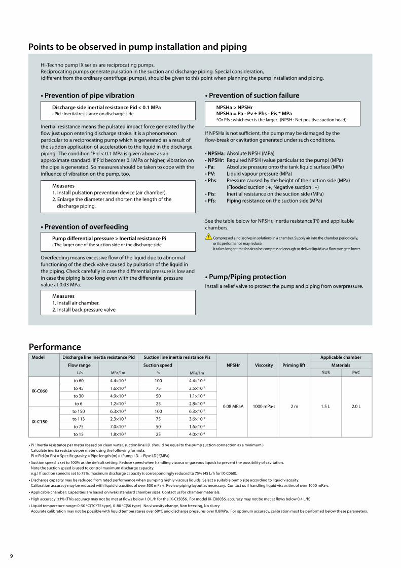
• Pi : Inertia resistance per meter (based on clean water, suction line I.D. should be equal to the pump suction connection as a minimum.) Calculate inertia resistance per meter using the following formula.Pi = Pid (or Pis) × Specific gravity × Pipe length (m) × (Pump I.D. ÷ Pipe I.D.)2(MPa)
• Suction speed is set to 100% as the default setting. Reduce speed when handling viscous or gaseous liquids to prevent the possibility of cavitation.Note the suction speed is used to control maximum discharge capacity.e.g.) If suction speed is set to 75%, maximum discharge capacity is correspondingly reduced to 75% (45 L/h for IX-C060).
• Discharge capacity may be reduced from rated performance when pumping highly viscous liquids. Select a suitable pump size according to liquid viscosity.Calibration accuracy may be reduced with liquid viscosities of over 500 mPa•s. Review piping layout as necessary. Contact us if handling liquid viscosities of over 1000 mPa•s.
• Applicable chamber: Capacities are based on Iwaki standard chamber sizes. Contact us for chamber materials.
• High accuracy: ±1% (This accuracy may not be met at flows below 1.0 L/h for the IX-C150S6. For model IX-C060S6, accuracy may not be met at flows below 0.4 L/h)
• Liquid temperature range: 0-50 ºC(TC/TE type), 0-80 ºC(S6 type) No viscosity change, Non freezing, No slurryAccurate calibration may not be possible with liquid temperatures over 60ºC and discharge pressures over 0.8MPa. For optimum accuracy, calibration must be performed below these parameters.
Suction speed
%
NPSHr Viscosity Priming lift Flow range
Discharge line inertia resistance Pid Suction line inertia resistance Pis Applicable chamber
L/h MPa/1m
Materials
SUS PVC
Model
MPa/1m
IX-C060
IX-C150
to 60
to 45
to 30
to 6
to 150
to 113
to 75
to 15
4.4×10⁻³
1.6×10⁻³
4.9×10⁻⁴
1.2×10⁻⁵
6.3×10⁻³
2.3×10⁻³
7.0×10⁻⁴
1.8×10⁻⁵
100
75
50
25
100
75
50
25
4.4×10⁻³
2.5×10⁻³
1.1×10⁻³
2.8×10⁻⁴
0.08 MPaA 1000 mPa•s 2 m 1.5 L 2.0 L6.3×10-3
3.6×10⁻³
1.6×10⁻³
4.0×10⁻⁴
Performance
Points to be observed in pump installation and piping
• Prevention of pipe vibration
• Prevention of overfeedingPump dierential pressure > Inertial resistance Pi• The larger one of the suction side or the discharge side
Measures1. Install pulsation prevention device (air chamber).2. Enlarge the diameter and shorten the length of the
discharge piping.
Discharge side inertial resistance Pid < 0.1 MPa• Pid : Inertial resistance on discharge side
Hi-Techno pump IX series are reciprocating pumps.Reciprocating pumps generate pulsation in the suction and discharge piping. Special consideration, (different from the ordinary centrifugal pumps), should be given to this point when planning the pump installation and piping.
Inertial resistance means the pulsated impact force generated by the flow just upon entering discharge stroke. It is a phenomenon particular to a reciprocating pump which is generated as a result of the sudden application of acceleration to the liquid in the discharge piping. The condition "Pid < 0.1 MPa is given above as an approximate standard. If Pid becomes 0.1MPa or higher, vibration on the pipe is generated. So measures should be taken to cope with the influence of vibration on the pump, too.
• Prevention of suction failureNPSHa > NPSHrNPSHa = Pa - Pv ± Phs - Pis * MPa*Or Pfs : whichever is the larger. (NPSH : Net positive suction head)
If NPSHa is not sufficient, the pump may be damaged by the flow-break or cavitation generated under such conditions.
• NPSHa: Absolute NPSH (MPa)• NPSHr: Required NPSH (value particular to the pump) (MPa)• Pa: Absolute pressure onto the tank liquid surface (MPa)• PV: Liquid vapour pressure (MPa)• Phs: Pressure caused by the height of the suction side (MPa) (Flooded suction : +, Negative suction : –)• Pis: Inertial resistance on the suction side (MPa)• Pfs: Piping resistance on the suction side (MPa)
Overfeeding means excessive flow of the liquid due to abnormal functioning of the check valve caused by pulsation of the liquid in the piping. Check carefully in case the differential pressure is low and in case the piping is too long even with the differential pressure value at 0.03 MPa.
See the table below for NPSHr, inertia resistance(Pi) and applicable chambers.
Measures1. Install air chamber.2. Install back pressure valve
Compressed air dissolves in solutions in a chamber. Supply air into the chamber periodically, or its performance may reduce.It takes longer time for air to be compressed enough to deliver liquid as a flow rate gets lower.
• Pump/Piping protectionInstall a relief valve to protect the pump and piping from overpressure.
9

Max. capacityL/min (L/h)
Setting pressureMPa
ConnectionJIS10K Flange
Masskg
Model Wet-end materials
RV-7TV-15
RV-7TE-15
RV-7TV-25PVDF PTFE 7.5 (450) 0.3 - 0.8 5
RV-7TE-25
15A
25A
FKM
EPDM
FKM
EPDM
RV-2S6-15
RV-2S6B-15
RV-7S6-25
2.0 (120)
7.5 (450)
3.5
6
SUS316PTFE
SCS14
RV-7S6B-25
0.3 - 0.8
0.8 - 1.5
0.3 - 0.8
0.8 - 1.5
15A
15A (JIS16K)
25A
25A (JIS16K)
RV-3P-15
RV-3P-20 PVC PTFE 3.0 (180) 0.3 - 1.0
RV-3P-25
0.6
0.9
15A
20A
25A
CapacityL/min (L/h)
Setting pressureMPa
ConnectionJIS10K Flange
Masskg
Model Wet-end materials
BV-7TV-15
BV-7TE-15
BV-7TV-25PVDF PTFE 0.2 - 7.0 (12 - 420) 0.05 - 0.8 5
BV-7TE-25
15A
25A
FKM
EPDM
FKM
EPDM
BV-2S6-15
BV-7S6-25
BV-3NV-15
SUS316PTFE 0.05 - 0.8
SCS14
3.5
6
0.02 - 2.0 (1.2 - 120)
0.2 - 7.5 (12 - 450)
BV-3NV-20
15A
25A
15A
20A
BV-3NV-25
BV-3NE-15PVC 0.03 - 3.0 (1.8 - 180) 0.1 - 0.3
BV-3NE-20
FKM
EPDM
25A
15A
20A
BV-3NE-25 25A
0.6
0.9
0.6
0.9
CapacityL
Max. pressureMPa
ConnectionJIS10K Flange
Masskg
Model Wet-end materials
A-1S6-15
A-1S6-20 SUS316
A-1S6-25
15A
20A 5
25A
A-2VVPVC
1.5
2
0.9
0.5 2.515 - 25A sharedA-2VE
FKM O rings (A-2VV) and EPDM O rings (A-2VE) are not wet end materials.
Contact us for use at smaller ow rates than the above.
Relief valve Model RV
Back pressure valve Model BV
Air chamber Model AThe air chamber reduces ow pulsation to prevent piping vibration and overfeeding. An air chamber designed for slurry transfer is also available.Contact us for detail.
Reciprocating pumps keep running even in closed-discharge operation, resulting in piping breakage and motor failure by overpressure without a relief valve. Always install the relief valve to prevent overpressure in a discharge line.
Install a back pressure valve when discharge-line pressure is less than 0.03 MPa or less than than suction-line pressure. Pump check valves may otherwise not operate correctly and overfeeding may result. Dierential pressure between discharge and suction lines must be 0.03 MPa or more and also greater than the inertia resistance (Pid or Pis, whichever greater). Dierential pressure (0.03 MPa or more) > Inertia resistance (Pid or Pis, whichever is greater)
3
2
1
3
1 2
Air vent
IX series
Drain
Tank
Air chamber
Pressure gauge
Relief valve Back pressure valveDischarge piping
Suction piping
10
IWAKI HI-TECHNO PUMPS IX
Optional accessories / example of piping
PVC typeSUS type

( )Country codes
Actual pumps may dier from the photos. Specications and dimensions are subject to change without prior notice. For further details please contact us.
TEL: (49)2154 9254 0TEL: (49)2154 9254 50TEL: (31)74 2420011TEL: (39)0444 371115TEL: (34)93 37 70 198TEL: (32)13 67 02 00TEL: (45)48 24 2345TEL: (358)9 2745810TEL: (33)1 69 63 33 70TEL: (47)23 38 49 00TEL: (46)8 511 72900TEL: (44)1743 231363
FAX: 2154 9254 48FAX: 2154 9254 55FAX: (49)2154 925448FAX: 0444 335350FAX: 93 47 40 991FAX: 13 67 20 30FAX: 48 24 2346FAX: 9 2742715FAX: 1 64 49 92 73FAX: 23 38 49 01FAX: 8 511 72922FAX: 1743 366507
: IWAKI Europe GmbH: IWAKI Europe GmbH: IWAKI Europe GmbH (Netherlands Branch): IWAKI Europe GmbH (Italy Branch): IWAKI Europe GmbH (Spain Branch): IWAKI Belgium N.V.: IWAKI Nordic A/S : IWAKI Suomi Oy: IWAKI France S.A.: IWAKI Norge AS: IWAKI Sverige AB: IWAKI Pumps (UK) Ltd.
European oceGermanyHollandItalySpainBelgiumDenmarkFinlandFranceNorwaySwedenU.K.
Caution for safety use: Before use of pump, read instruction manual carefully to use the product correctly.
The posting and copying from this catalogue without permission is not accepted rmly.
IWAKI has global net work.Please nd your distributor location at
w w w.iwak ipumps. jp
Our products and/or parts of products fall in the category of goods contained in control list of international regime for export control. Please be reminded that export license could be required when products are exported due to export control regulations of countries.Legal attention related to export.
6-6 Kanda-Sudacho 2-chome Chiyoda-ku Tokyo 101-8558 JapanTEL : (81)3 3254 2935 FAX : 3 3252 8892
TEL: (1)508 429 1440TEL: (54)11 4745 4116TEL: (65)6316 2028TEL: (62)21 6906606TEL: (60)3 7803 8807TEL: (61)2 9899 2411TEL: (852)2607 1168TEL: (86)20 84350603TEL: (86)21 6272 7502TEL: (82)2 2630 4800TEL: (886)2 8227 6900TEL: (66)2 322 2471 TEL: (84)613 933456
FAX: 508 429 1386
FAX: 6316 3221FAX: 21 6906612FAX: 3 7803 4800FAX: 2 9899 2421FAX: 2607 1000FAX: 20 84359181FAX: 21 6272 6929FAX: 2 2630 4801FAX: 2 8227 6818FAX: 2 322 2477FAX: 613 933399
: IWAKI America Inc.: IWAKI America Inc. (Argentina Branch): IWAKI Singapore Pte Ltd.: IWAKI Singapore (Indonesia Branch): IWAKIm Sdn. Bhd.: IWAKI Pumps Australia Pty Ltd.: IWAKI Pumps Co., Ltd.: GFTZ IWAKI Engineering & Trading Co., Ltd.: IWAKI Pumps (Shanghai) Co., Ltd.: IWAKI Korea Co.,Ltd.: IWAKI Pumps Taiwan Co., Ltd.: IWAKI (Thailand) Co.,Ltd.: IWAKI Pumps Vietnam Co., Ltd.
U.S.A.ArgentinaSingaporeIndonesiaMalaysiaAustraliaHong KongChina
KoreaTaiwanThailandVietnam
CAT-W 0031-05 2015.03.PDF
Dimensions in mm
IX-C150TC, IX-C150TE
IX-C150S6
IX-C150TC, IX-C150TE
IX-C060S6
IX-C060TC, IX-060TE
(115)
(20)
(ø6)
(ø7.
5)
142156
199
1135 135
102
11
294
126
9
(45)
(47)(386)
(365)
142156
199
294
(421
)
(45)
(365)
Drain hole
Option
1950Power cord length
317
(34)
(365)
(359)(359)
287
(48)
335
(24) 199
(421
)
(365)199
(421
)
142156
142156
(365)199
(421
)
142156
270
(57)
(365)
335
(25)
325
(30)
(365)
240
(72)
Output terminal
The terminal forexternal control signal
The terminal forSTOP signal
Fieldbus terminal
AUX terminal
Power cord
IWAKI HI-TECHNO PUMPS IX


![[Suction Pump] Servicemanual Master Senator Eng](https://img.dokumen.tips/doc/110x75/577c856a1a28abe054bd0e4d/suction-pump-servicemanual-master-senator-eng.jpg)