Embed Size (px)
Citation preview

I n t e r n a t i o n a l T e l e c o m m u n i c a t i o n U n i o n
ITU-T G.873.1 TELECOMMUNICATION STANDARDIZATION SECTOR OF ITU
(10/2017)
SERIES G: TRANSMISSION SYSTEMS AND MEDIA, DIGITAL SYSTEMS AND NETWORKS
Digital networks – Optical transport networks
Optical transport network: Linear protection
Recommendation ITU-T G.873.1

ITU-T G-SERIES RECOMMENDATIONS
TRANSMISSION SYSTEMS AND MEDIA, DIGITAL SYSTEMS AND NETWORKS
INTERNATIONAL TELEPHONE CONNECTIONS AND CIRCUITS G.100–G.199
GENERAL CHARACTERISTICS COMMON TO ALL ANALOGUE CARRIER-TRANSMISSION SYSTEMS
G.200–G.299
INDIVIDUAL CHARACTERISTICS OF INTERNATIONAL CARRIER TELEPHONE SYSTEMS ON METALLIC LINES
G.300–G.399
GENERAL CHARACTERISTICS OF INTERNATIONAL CARRIER TELEPHONE SYSTEMS ON RADIO-RELAY OR SATELLITE LINKS AND INTERCONNECTION WITH METALLIC LINES
G.400–G.449
COORDINATION OF RADIOTELEPHONY AND LINE TELEPHONY G.450–G.499
TRANSMISSION MEDIA AND OPTICAL SYSTEMS CHARACTERISTICS G.600–G.699
DIGITAL TERMINAL EQUIPMENTS G.700–G.799
DIGITAL NETWORKS G.800–G.899
General aspects G.800–G.809
Design objectives for digital networks G.810–G.819
Synchronization, quality and availability targets G.820–G.829
Network capabilities and functions G.830–G.839
SDH network characteristics G.840–G.849
Management of transport network G.850–G.859
SDH radio and satellite systems integration G.860–G.869
Optical transport networks G.870–G.879
DIGITAL SECTIONS AND DIGITAL LINE SYSTEM G.900–G.999
MULTIMEDIA QUALITY OF SERVICE AND PERFORMANCE – GENERIC AND USER-RELATED ASPECTS
G.1000–G.1999
TRANSMISSION MEDIA CHARACTERISTICS G.6000–G.6999
DATA OVER TRANSPORT – GENERIC ASPECTS G.7000–G.7999
PACKET OVER TRANSPORT ASPECTS G.8000–G.8999
ACCESS NETWORKS G.9000–G.9999
For further details, please refer to the list of ITU-T Recommendations.

Rec. ITU-T G.873.1 (10/2017) i
Recommendation ITU-T G.873.1
Optical transport network: Linear protection
Summary
Recommendation ITU-T G.873.1 defines the automatic protection switching (APS) protocol and
protection switching operation for the linear protection schemes for the optical transport network at
the optical data unit k (ODUk) level. Protection schemes considered in this Recommendation are:
– ODUk subnetwork connection protection with inherent monitoring (1+1, 1:n);
– ODUk subnetwork connection protection with non-intrusive monitoring (1+1);
– ODUk subnetwork connection protection with sublayer monitoring (1+1, 1:n).
– ODUk compound link subnetwork connection group protection with inherent monitoring
(1+1, 1:1).
In addition, client-related protection architectures are described.
History
Edition Recommendation Approval Study Group Unique ID*
1.0 ITU-T G.873.1 2003-03-29 15 11.1002/1000/6306
2.0 ITU-T G.873.1 2006-03-29 15 11.1002/1000/8762
3.0 ITU-T G.873.1 2011-07-22 15 11.1002/1000/11120
3.1 ITU-T G.873.1 (2011) Amd. 1 2012-10-29 15 11.1002/1000/11790
4.0 ITU-T G.873.1 2014-05-14 15 11.1002/1000/12181
4.1 ITU-T G.873.1 (2014) Amd. 1 2014-12-05 15 11.1002/1000/12368
5.0 ITU-T G.873.1 2017-10-07 15 11.1002/1000/13302
* To access the Recommendation, type the URL http://handle.itu.int/ in the address field of your web
browser, followed by the Recommendation's unique ID. For example, http://handle.itu.int/11.1002/1000/
11830-en.

ii Rec. ITU-T G.873.1 (10/2017)
FOREWORD
The International Telecommunication Union (ITU) is the United Nations specialized agency in the field of
telecommunications, information and communication technologies (ICTs). The ITU Telecommunication
Standardization Sector (ITU-T) is a permanent organ of ITU. ITU-T is responsible for studying technical,
operating and tariff questions and issuing Recommendations on them with a view to standardizing
telecommunications on a worldwide basis.
The World Telecommunication Standardization Assembly (WTSA), which meets every four years,
establishes the topics for study by the ITU-T study groups which, in turn, produce Recommendations on
these topics.
The approval of ITU-T Recommendations is covered by the procedure laid down in WTSA Resolution 1.
In some areas of information technology which fall within ITU-T's purview, the necessary standards are
prepared on a collaborative basis with ISO and IEC.
NOTE
In this Recommendation, the expression "Administration" is used for conciseness to indicate both a
telecommunication administration and a recognized operating agency.
Compliance with this Recommendation is voluntary. However, the Recommendation may contain certain
mandatory provisions (to ensure, e.g., interoperability or applicability) and compliance with the
Recommendation is achieved when all of these mandatory provisions are met. The words "shall" or some
other obligatory language such as "must" and the negative equivalents are used to express requirements. The
use of such words does not suggest that compliance with the Recommendation is required of any party.
INTELLECTUAL PROPERTY RIGHTS
ITU draws attention to the possibility that the practice or implementation of this Recommendation may
involve the use of a claimed Intellectual Property Right. ITU takes no position concerning the evidence,
validity or applicability of claimed Intellectual Property Rights, whether asserted by ITU members or others
outside of the Recommendation development process.
As of the date of approval of this Recommendation, ITU had not received notice of intellectual property,
protected by patents, which may be required to implement this Recommendation. However, implementers
are cautioned that this may not represent the latest information and are therefore strongly urged to consult the
TSB patent database at http://www.itu.int/ITU-T/ipr/.
ITU 2017
All rights reserved. No part of this publication may be reproduced, by any means whatsoever, without the
prior written permission of ITU.

Rec. ITU-T G.873.1 (10/2017) iii
Table of Contents
Page
1 Scope ...................................................................................................................................... 1
2 References .............................................................................................................................. 1
3 Definitions ............................................................................................................................. 1
3.1 Terms defined elsewhere ......................................................................................... 1
3.2 Terms defined in this Recommendation .................................................................. 2
4 Abbreviations and acronyms ................................................................................................. 2
5 Conventions ........................................................................................................................... 3
6 Protection characteristics ....................................................................................................... 4
6.1 Monitoring methods and conditions ........................................................................ 4
6.2 Protection switching performance ........................................................................... 6
7 Protection group commands .................................................................................................. 6
7.1 End-to-end commands and states ............................................................................ 6
7.2 Local commands ...................................................................................................... 7
8 Protection architectures ......................................................................................................... 8
8.1 Unidirectional and bidirectional switching ............................................................. 8
8.2 Need for an APS/PCC channel ................................................................................ 9
8.3 Revertive and non-revertive switching .................................................................... 9
8.4 Provisioning mismatches ......................................................................................... 9
8.5 Overview of protection architectures for OTN linear protection ............................ 10
9 APS protocol .......................................................................................................................... 11
9.1 APS channel format ................................................................................................. 11
9.2 Transmission and acceptance of APS protocol ....................................................... 12
9.3 Request type ............................................................................................................ 13
9.4 Protection types ....................................................................................................... 14
9.5 Requested signal ...................................................................................................... 14
9.6 Bridged signal .......................................................................................................... 15
9.7 Control of bridge ..................................................................................................... 15
9.8 Control of selector ................................................................................................... 15
9.9 Signal Fail of the protection entity .......................................................................... 15
9.10 Equal priority requests ............................................................................................. 15
9.11 Command acceptance and retention ........................................................................ 16
9.12 Hold-off timer .......................................................................................................... 16
9.13 Exercise operation ................................................................................................... 16
9.14 APS channel alarming ............................................................................................. 17
iv Rec. ITU-T G.873.1 (10/2017)
Page
9.15 SF persistency timer ................................................................................................ 17
Appendix I – Examples of operation ................................................................................................ 18
I.1 1+1 unidirectional switching ................................................................................... 18
I.2 1+1 bidirectional switching ..................................................................................... 18
I.3 1:n bidirectional switching ...................................................................................... 19
I.4 Exercise command operation .................................................................................. 20
Appendix II – ODUk client protection ............................................................................................. 23
II.1 Overview over protection architectures of OTN linear client protection ................ 23
II.2 Model of client SNC/Nc protection architecture of OTN linear client
protection ................................................................................................................. 23
II.3 Model of client SNC/I protection architectures of OTN linear client
protection ................................................................................................................. 24
Appendix III – Media layer protection ............................................................................................. 27
III.1 Overview of media layer protection ........................................................................ 27
III.2 Media layer protection types ................................................................................... 27
Bibliography...................................................................................................................................... 32

Rec. ITU-T G.873.1 (10/2017) 1
Recommendation ITU-T G.873.1
Optical transport network: Linear protection
1 Scope
This Recommendation defines the automatic protection switching (APS) protocol and protection
switching operation for the linear protection schemes for the optical transport network (OTN) at the
optical data unit k (ODUk) level. These schemes are based on the generic linear protection
specifications in [ITU-T G.808.1]. Linear protection schemes considered in this Recommendation
are:
– ODUk subnetwork connection protection with inherent monitoring (1+1, 1:n);
– ODUk subnetwork connection protection with non-intrusive monitoring (1+1);
– ODUk subnetwork connection protection with sublayer monitoring (1+1, 1:n);
– ODUk compound link subnetwork connection group protection with inherent monitoring
(1+1, 1:1).
In addition, client-related protection architectures are described.
2 References
The following ITU-T Recommendations and other references contain provisions which, through
reference in this text, constitute provisions of this Recommendation. At the time of publication, the
editions indicated were valid. All Recommendations and other references are subject to revision;
users of this Recommendation are therefore encouraged to investigate the possibility of applying the
most recent edition of the Recommendations and other references listed below. A list of the
currently valid ITU-T Recommendations is regularly published. The reference to a document within
this Recommendation does not give it, as a stand-alone document, the status of a Recommendation.
[ITU-T G.709] Recommendation ITU-T G.709/Y.1331 (2016), Interfaces for the optical
transport network.
[ITU-T G.798] Recommendation ITU-T G.798 (2017), Characteristics of optical transport
network hierarchy equipment functional blocks.
[ITU-T G.798.1] Recommendation ITU-T G.798.1 (2013), Types and characteristics of optical
transport network equipment.
[ITU-T G.806] Recommendation ITU-T G.806 (2012), Characteristics of transport
equipment – Description methodology and generic functionality.
[ITU-T G.808] Recommendation ITU-T G.808 (2016), Terms and definitions for network
protection and restoration.
[ITU-T G.808.1] Recommendation ITU-T G.808.1 (2014), Generic protection switching –
Linear trail and subnetwork protection.
3 Definitions
3.1 Terms defined elsewhere
This Recommendation uses the following terms defined elsewhere:
Terms defined in [ITU-T G.808]:
– APS channel;

2 Rec. ITU-T G.873.1 (10/2017)
– extra traffic signal;
– head-end;
– normal traffic signal;
– null signal;
– protection communication channel;
– protection group;
– signal;
– tail-end.
3.2 Terms defined in this Recommendation
None.
4 Abbreviations and acronyms
This Recommendation uses the following abbreviations and acronyms:
AIS Alarm Indication Signal
APS Automatic Protection Switching
CBR Constant Bit Rate signal
CL_SNCG/I Compound Link Subnetwork Connection Group protection with Inherent
monitoring
CSF Client Signal Fail
DNR Do Not Revert
ETC3 Ethernet Coding 1000BASE-X
EXER Exercise
FDI Forward Defect Indication
FS Forced Switch
HO Higher Order
LCK Locked defect
LO Lower Order
LoP Lockout for Protection
MFAS Multiframe Alignment Signal
MS Manual Switch
NIM Non-Intrusive Monitor
NR No Request
OCI Open Connection Indication
ODU[i]j_A ODUkP to ODU[i]j Adaptation function
ODU[i]j_A_SK ODUkP to ODU[i]j Adaptation Sink function
ODUj-21_A ODUj payload type 21 Adaptation function
ODUk Optical Data Unit k
ODUk_A Optical Data Unit Adaptation of rate K

Rec. ITU-T G.873.1 (10/2017) 3
ODUk_A_Sk ODUk Adaptation Sink function
ODUk[i]j ODUj[/i] Optical Data Unit of level j or i (i is optional; i < j)
ODUkP Optical Data Unit of level k, Path
ODUkT Optical Data Unit of level k, Tandem connection sub-layer
OPU Optical Payload Unit
OTN Optical Transport Network
OTUk Optical Transport Unit k
OTUkV Functionally standardized Optical Transport Unit k
OTUk[V] OTUk or OTUkV
PCC Protection Communication Channel
PMOH Path Monitoring Overhead
RR Reverse Request
SD Signal Degrade
SDH Synchronous Digital Hierarchy
SF Signal Fail
SMOH Section Monitoring Overhead
SNC Subnetwork Connection
SNC/I Subnetwork Connection with Inherent monitoring
SNC/Nc Subnetwork Connection with Non-intrusive monitoring of Client signal fail
SNC/Ne Subnetwork Connection with Non-intrusive end-to-end monitoring
SNC/Ns Subnetwork Connection with Non-intrusive Sublayer monitoring
SNC/S Subnetwork Connection with Sub-layer monitoring
SSD Server Signal Degraded
SSF Server Signal Fail
TCM Tandem Connection Monitoring
TCMOH Tandem Connection Monitoring Overhead
TSD Trail Signal Degraded
TSF Trail Signal Fail
TTI Trail Trace Identifier
WTR Wait-to-Restore
5 Conventions
None.

4 Rec. ITU-T G.873.1 (10/2017)
6 Protection characteristics
6.1 Monitoring methods and conditions
Protection switching will occur based on the detection of certain defects on the transport entities
(working and protection) within the protected domain. How these defects are detected is the subject
of the equipment Recommendations (e.g., [ITU-T G.806] and [ITU-T G.798]). For the purpose of
the protection switching controller, an entity within the protected domain has a condition of
no defect = OK, degraded (signal degrade = SD), or failed (signal fail = SF).
The customary monitoring methods are specified in clauses 11.2 and 11.3 of [ITU-T G.808.1] and
in clause 14.1 of [ITU-T G.798] and are supported in the OTN as follows:
Inherent – Protection switching is triggered by defects detected at the ODUk link connection
(e.g., server layer trail and server/ODUk adaptation function). The trail termination sink of an
(OTUk[V] or ODUkP) server layer provides the test signal fail (TSF)- and test signal degraded
(TSD)-based SF and SD protection switching criteria via the OTUk[V]/ODUk_A,
ODUkP/ODU[i]j_A, or ODUkP/ODUj-21_A functions (as SSF and SSD). No defect detection is
performed on the ODUk or ODU[i]j or ODUj signals themselves. It can be used for individual and
for compound link group protection (CL_SNCG/I).
NOTE 1 – In contrast to SDH SNC/I, ODUk SNC/I can stretch only a single link connection, as the FDI/AIS
defect resulting from further upstream server layer defects is not detected in the server/ODUk adaptation
function. The limitation to a single server layer trail for SNC/I protection is given by the use of signal
degrade (SD) as protection switching criteria. SD is only available from the OTUk[V] or HO ODUk trail that
is locally terminated and not from further upstream OTUk[V] or HO ODUk trails. Furthermore, FDI/AIS,
which provides information about defects in upstream OTUk[V] or HO ODUk trails, is not detected in the
OTUk[V]/ODUk_A_Sk or ODUkP/ODU[i]j_A_Sk. For details of the atomic functions for TSF TSD
forwarding for the subnetwork connection (SNC) protection on LO ODU refer to [ITU-T G.798].
Figure 6-1 shows an OTUk or OTUkV monitored ODUk SNC/I protection configuration.
Figure 6-1 – OTUk or OTUkV monitored ODUk SNC/I protection configuration
Figure 6-2 shows a server ODUk monitored ODU[i]j/ODUj SNC/I protection configuration.

Rec. ITU-T G.873.1 (10/2017) 5
Figure 6-2 – Server ODUk monitored ODU[i]j/ODUj SNC/I protection configuration
Non-intrusive – Protection switching is triggered by a non-intrusive monitor of the ODUkP trail or
ODUkT sub-layer trail at the tail-end of the protection group.
NOTE 2 – For a SNC/N protection the criteria according to [ITU-T G.798] are taken. This ensures that
ODUk-AIS as well a Locked or open connection indication (OCI) condition is contributing to switch criteria
of an ODU SNC/N protection. For details refer to clause 14.2 of [ITU-T G.798].
Figure 6-3 shows an ODUkP non-intrusively monitored ODUk SNC/Ne configuration and
an ODUkT monitored ODUk SNC/Ns protection configuration.
Figure 6-3 – ODUkP non-intrusively monitored ODUk SNC/Ne and
ODUkT monitored ODUk SNC/Ns protection configurations

6 Rec. ITU-T G.873.1 (10/2017)
Sublayer – Protection switching is triggered by defects detected at the ODUkT sublayer trail
(TCM). An ODUkT sublayer trail is established for each working and protection entity. Protection
switching is therefore triggered only on defects of the protected domain. Figure 6-4 shows an
ODUkT monitored SNC/S protection configuration.
Figure 6-4 – ODUkT monitored SNC/S protection configuration
The protection switching controller does not care which monitoring method is used, as long as it
can be given (OK, SD, SF) information for the transport entities within the protected domain. Some
monitors or network layers may not have an SD detection method. Where this is the case, there is
no need to use a different APS protocol – it would simply happen that an SD would not be issued
from equipment that cannot detect it. Where an APS protocol is used, the implementation should
not preclude that the far end declares an SD over the APS channel, even if the monitor at the near-
end cannot detect SD.
NOTE 3 – In accordance with [ITU-T G.709], for sublayer monitoring, nesting and cascading are the default
operational configurations. Overlapping is an additional configuration for testing purposes only. Overlapped
monitored connections must be operated in a non-intrusive mode and not used for protection. Maintenance
signals ODUk-AIS and ODUk-LCK must not be generated for overlapped monitored connections. For the
case where one of the endpoints in an overlapping monitored connection is located inside a SNC protected
domain while the other endpoint is located outside the protected domain, the SNC protection should be
forced to working when the endpoint of the overlapping monitored connection is located on the working
connection and forced to protection when the endpoint is located on the protection connection.
6.2 Protection switching performance
The transfer time Tt, as defined in clause 13 of [ITU-T G.808.1], shall not exceed 50 ms for a
protection span length that does not exceed 1200 km.
7 Protection group commands
7.1 End-to-end commands and states
This clause describes commands that apply to the protection group as a whole. When an APS is
present, these commands are signalled to the far end of the connection. In bidirectional switching,
these commands affect the bridge and selector at both ends.

Rec. ITU-T G.873.1 (10/2017) 7
Lockout of protection – This command prevents a working signal from being selected from the
protection entity. This effectively disables the protection group. An extra traffic signal, if present on
the protection entity, is dropped.
Force switch normal traffic signal #n to protection – Forces normal traffic signal #n to be selected
from the protection entity after the required bridge is present.
Force switch null signal – For 1:n architectures, it switches the null signal to the protection entity,
unless an equal or higher priority switch command is in effect. A normal traffic signal present on
the protection entity is transferred to and selected from its working entity. For 1+1 architectures, it
selects the normal traffic signal from the working entity.
Force switch extra traffic signal – It switches the extra traffic signal to the protection entity, unless
an equal or higher priority switch command is in effect. A normal traffic signal present on the
protection entity is transferred to and selected from its working entity.
Manual switch normal traffic signal #n to protection – In the absence of a failure of a working or
protection entity, forces a normal traffic signal #n to be selected from the protection entity after the
required bridge is present.
Manual switch null signal – For 1:n architectures, it switches the null signal to the protection entity,
unless a fault condition exists on other entities or an equal or higher priority switch command is in
effect. A normal traffic signal present on the protection entity is transferred to and selected from its
working entity. For 1+1 architectures, it selects the normal traffic signal from the working entity.
Manual switch extra traffic signal – It switches extra traffic signal to the protection entity, unless a
fault condition exists on other entities or an equal or higher priority switch command is in effect. A
normal traffic signal present on the protection entity is transferred to and selected from its working
entity.
Wait-to-restore normal traffic signal #n – In revertive operation, after the clearing of an SF or SD
on a working entity #n, maintains a normal traffic signal #n as selected from the protection entity
until a Wait-to-Restore timer expires. If the timer expires prior to any other event or command, the
state will be changed to no request (NR). This is used to prevent frequent operation of the selector
in the case of intermittent failures.
Exercise signal #n – Exercise of the APS protocol. The signal is chosen so as not to modify the
selector.
Do not revert normal traffic signal #n – In non-revertive operation, this is used to maintain a normal
traffic signal selected from the protection entity.
No request – All normal traffic signals are selected from their corresponding working transport
entities. The protection entity carries either the null signal, extra traffic, or a bridge of the single
normal traffic signal in a 1+1 protection group.
Clear – Clears the active near-end Lockout of Protection, Forced Switch, Manual Switch,
WTR state, or Exercise command.
7.2 Local commands
These commands apply only to the near-end of the protection group. When an APS is present, they
have not been signalled to the far end via the APS channel.
Freeze – Freezes the state of the protection group. Until the freeze is cleared, additional near-end
commands are rejected. Condition changes and received APS bytes are ignored. When the Freeze
command is cleared, the state of the protection group is recomputed based on the condition and
received APS bytes.

8 Rec. ITU-T G.873.1 (10/2017)
Clear freeze
Lockout normal traffic signal #n from protection – Prevents normal traffic signal #n from being
selected from the protection entity. Commands for normal traffic signal #n will be rejected. SF or
SD will be ignored for normal traffic signal #n. In bidirectional 1:n switching, remote bridge
requests for normal traffic signal #n will still be honoured to prevent protocol failures. As a result, a
normal traffic signal must be locked out from protection at both ends to prevent it being selected
from the protection entity as a result of a command or failure at either end. Multiple of these
commands may coexist for different normal traffic signals.
Clear lockout normal traffic signal #n from protection
8 Protection architectures
In a linear protection architecture, protection switching occurs at the two distinct endpoints of
a protected trail or protected subnetwork connection. Between these endpoints, there will be both
"working" and "protection" entities.
For a given direction of transmission, the "head-end" of the protected signal is capable of
performing a bridge function, which will place a copy of a normal traffic signal onto a protection
entity when required. The "tail-end" will perform a selector function, where it is capable of
selecting a normal traffic signal either from its usual working entity, or from a protection entity.
In the case of bidirectional transmission, where both directions of transmission are protected, both
ends of the protected signal will normally provide both bridge and selector functions.
The following architectures are possible:
1+1 – In a 1+1 architecture, a single normal traffic signal is protected by a single protection entity.
The bridge at the head-end is permanent. Switching occurs entirely at the tail-end.
1:n – In a 1:n architecture, 1 or more normal traffic signal(s) are protected by a single protection
entity. The bridge at the head-end is not established until a protection switch is required. In the case
where n > 1, it cannot be known which of the normal traffic signals should be bridged onto the
protection entity, until a defect is detected on one of the protected signals. 1:n architectures are
capable of carrying an extra (low priority, pre-emptable) traffic signal on the protection entity when
it is not being used to protect any normal traffic signal. A 1:n architecture can be used even for
n = 1 (1:1). This might be chosen over the simpler 1+1 architecture (which requires no head-end
actions of the protection algorithm) since 1:1 is capable of carrying extra traffic, where 1+1 is not.
m:n – In this architecture, m protection entities are used to protect n working entities. This is for
further study.
With the assumption of a larger APS channel, the coding for the entity number "n" will use a full
byte rather than the few bits in synchronous digital hierarchy (SDH). Two of the 256 values are
reserved: 0 is used to indicate a null signal or the protection entity and 0xFF (255) is used to
indicate extra traffic.
The architecture at each end of the connection must match.
8.1 Unidirectional and bidirectional switching
In the case of bidirectional transmission, it is possible to choose either unidirectional or
bidirectional switching. With unidirectional switching, the selectors at each end are fully
independent. With bidirectional switching, an attempt is made to coordinate the two ends so that
both have the same bridge and selector settings, even for a unidirectional failure. Bidirectional
switching always requires an APS and/or protection communication channel (PCC) to coordinate
the two endpoints. Unidirectional switching can protect two unidirectional failures in opposite
directions on different entities.

Rec. ITU-T G.873.1 (10/2017) 9
8.2 Need for an APS/PCC channel
The only switching type that does not require an APS and/or PCC channel is 1+1 unidirectional
switching. With a permanent bridge at the head-end and no need to coordinate selector positions at
the two ends, the tail-end selector can be operated entirely according to defects and commands
received at the tail-end.
Bidirectional switching always requires an APS channel. 1:n unidirectional switching requires an
APS channel to coordinate the head-end bridge with the tail-end selector.
8.3 Revertive and non-revertive switching
In revertive operation, traffic is restored to the working entities after a switch reason has cleared. In
the case of clearing a command (e.g., Forced Switch), this happens immediately. In the case of
clearing of a defect, this generally happens after the expiry of a "Wait-to-Restore" timer, which is
used to avoid chattering of selectors in the case of intermittent defects.
In non-revertive operation, normal traffic is allowed to remain on the protection entity even after
a switch reason has cleared. This is generally accomplished by replacing the previous switch
request with a "do not revert (DNR)" request, which is low priority.
1+1 protection is often provisioned as non-revertive, as the protection is fully dedicated in any case
and this avoids a second "glitch" to the traffic. There may, however, be reasons to provision this to
be revertive (e.g., so that the traffic uses the "short" direction around a ring except during failure
conditions. Certain operator policies also dictate revertive operation even for 1+1).
Usually, 1:n protection is revertive. Certainly in the case where an extra traffic signal is carried on
the protection entity, the operation would always be revertive so that the pre-empted extra traffic
signal can be restored. It is certainly possible to define the protocol in a way that would permit
non-revertive operation for 1:n protection, but the expectation is that it is better to revert and glitch
the traffic when the working entity is repaired than when some other entity in the group fails that
requires use of the protection entity to carry a different normal traffic signal.
In general, the choice of revertive/non-revertive will be the same at both ends of the protection
group. However, a mismatch of this parameter does not prevent interworking – it just would be
peculiar for one side to go to wait-to-restore (WTR) for clearing of switches initiated from that side,
while the other goes to DNR for its switches. See also clause 8.4.
8.4 Provisioning mismatches
With all of the options for provisioning of protection groups, there are opportunities for mismatches
between the provisioning at the two ends. These provisioning mismatches take one of several
forms:
– Mismatches where proper operation is not possible.
– Mismatches where one or both sides can adapt their operation to provide a degree of
interworking in spite of the mismatch.
– Mismatches that do not prevent interworking. An example is the revertive/non-revertive
mismatch discussed in clause 9.4.
Not all provisioning mismatches can be conveyed and detected by information passed through the
APS channel. With a potential for up to 254 working entities in a 1:n protection group, there are
simply too many combinations of valid entity numbers to easily provide full visibility of all the
configuration options. What is desirable, however, is to provide visibility for the middle category,
where the sides can adapt their operation to interwork in spite of the mismatch. For example, an
equipment provisioned for bidirectional switching could fall back to unidirectional switching to
allow interworking. An equipment provisioned for 1+1 switching with an APS channel could fall
back to operate in 1+1 unidirectional switching without an APS channel. The user could still be

10 Rec. ITU-T G.873.1 (10/2017)
informed of the provisioning mismatch, but a level of protection could still be provided by the
equipment.
NOTE – To prevent APS protocol mismatch in provisioning of interfaces in respect to configuration of linear
and other protection mechanisms, proper trail trace identifier (TTI) management should be used to detect
such situation.
8.5 Overview of protection architectures for OTN linear protection
Table 8-1 provides an overview of the linear OTN protection types which are supported by the
specifications in this Recommendation. It provides information of the possible supported protection
architectures versus the related supporting switching types, APS channel used, related server layers
and protected entities. It should be noted that the compound link group protection as specified in
[ITU-T G.808.1] includes support for unprotected service. This [ITU-T G.808.1] specification
needs to be considered for the compound link group protection classes.
Table 8-1 – Overview of linear OTN protection architectures and related monitoring
Protection
architecture
Swit-
ching
type
Protection
subclass
and
monitoring
ODU entities
for
protection
switching,
individual/
group
APS
channel
used and
MFAS in
bits 6-8
Server
layer of
protected
entity
Protection
switched
entity
Trigger
criteria
used
1+1 Unidir SNC/I Individual No One HO
ODUk or
one OTUk
ODUkP or
ODUkT
ODU
SSF/SSD
1+1 Bidir SNC/I Individual 111 One OTUk
or one HO
ODUk
ODUkP or
ODUkT
ODU
SSF/SSD
1:n Bidir SNC/I Individual 111 One OTUk
or one HO
ODUk
ODUkP or
ODUkT
ODU
SSF/SSD
1+1 Unidir SNC/Ne Individual No One or
more HO
ODUk
and/or
OTUk
ODUkP ODU
TSF/TSD
1+1 Bidir SNC/Ne Individual 000 One or
more HO
ODUk
and/or
OTUk
ODUkP ODU
TSF/TSD
1+1 Unidir SNC/Ns Individual4 No One or
more HO
ODUk
and/or
OTUk
ODUkT ODU
TSF/TSD
1+1 Bidir SNC/Ns Individual4 001-110 One or
more HO
ODUk
and/or
OTUk
ODUkT ODU
TSF/TSD
1+1 Unidir SNC/S Individual4 No One or
more HO
ODUk
ODUkT or
ODUkP
ODUkT
SSF/SSD

Rec. ITU-T G.873.1 (10/2017) 11
Table 8-1 – Overview of linear OTN protection architectures and related monitoring
Protection
architecture
Swit-
ching
type
Protection
subclass
and
monitoring
ODU entities
for
protection
switching,
individual/
group
APS
channel
used and
MFAS in
bits 6-8
Server
layer of
protected
entity
Protection
switched
entity
Trigger
criteria
used
and/or
OTUk
1+1 Bidir SNC/S Individual4 001-110 One or
more HO
ODUk
and/or
OTUk
ODUkT or
ODUkP
ODUkT
SSF/SSD
1:n Bidir SNC/S Individual4 001-110 One or
more HO
ODUk
and/or
OTUk
ODUkT or
ODUkP
ODUkT
SSF/SSD
1+1 Unidir CL-SNCG/I Group No One HO
ODUk
LO ODU HO
ODUkP
SSF/SSD
1+1 Bidir CL-SNCG/I Group HO 000 One HO
ODUk
LO ODU HO
ODUkP
SSF/SSD
1:1 Bidir CL-SNCG/I Group HO 000 One HO
ODUk
LO ODU HO
ODUkP
SSF/SSD
NOTE 1 – Bidir SNC/N, is supported but care should be taken in case of nested protection schemes as an APS
channel may be used by more than one protection scheme and/or protection scheme instance. It is recommended to
use 1+1 bidir SNC/S instead.
NOTE 2 – CL-SNCG/I can assign all Normal signal to the Na subgroup and leave the Nb subgroup empty.
NOTE 3 – The equipment models and required processes of the various architectures are given in the related
subclauses of clause 14.1 of [ITU-T G.798].
NOTE 4 – The SNC/S architecture may be implemented when there is HO/LO muxing with "emulation" of line
switching by switching all contained LO ODU connections. Examples are given in [ITU-T G.798.1].
9 APS protocol
9.1 APS channel format
An APS channel is carried over the first three bytes of the APS/PCC field of the ODUk overhead.
The fourth byte of the APS/PCC field is reserved. Eight independent APS channels are available to
support protection at the ODUkP, the six ODUkT (TCM) levels and one level of ODUk SNC/I
protection as defined in clause 15.8.2.4 of [ITU-T G.709].
The format of the four APS bytes themselves within each frame is defined in Figure 9-1. The field
values for the APS channels are defined in Table 9-1.

12 Rec. ITU-T G.873.1 (10/2017)
1 2 3 4
1 2 3 4 5 6 7 8 1 2 3 4 5 6 7 8 1 2 3 4 5 6 7 8 1 2 3 4 5 6 7 8
Request/
state
Protection
type
Requested Signal Bridged Signal Reserved
A B D R
Figure 9-1 – APS channel format
Table 9-1 – Field values for APS channels
Field Value Description
Request/State
1111 Lockout of protection (LoP)
1110 Forced switch (FS)
1100 Signal fail (SF)
1010 Signal degrade (SD)
1000 Manual switch (MS)
0110 Wait-to-restore (WTR)
0100 Exercise (EXER)
0010 Reverse request (RR)
0001 Do not revert (DNR)
0000 No request (NR)
Others Reserved for future international standardization
Protection
Type
A 0 No APS channel
1 APS channel
B 0 1+1 (permanent bridge)
1 1:n (no permanent bridge)
D 0 Unidirectional switching
1 Bidirectional switching
R 0 Non-revertive operation
1 Revertive operation
Requested Signal
0 Null signal
1-254 Normal traffic Signal 1-254
255 Extra traffic signal
Bridged Signal
0 Null signal
1-254 Normal traffic Signal 1-254
255 Extra traffic signal
9.2 Transmission and acceptance of APS protocol
The APS/PCC protocol is transmitted via the protection entity. Although it may also be transmitted
identically on working entities, receivers should not assume so and should have the capability to
ignore this information on the working entities.
For each of the eight levels, an independent acceptance process shall be performed. As the APS
protocol is carried via the first three of the four APS/PCC bytes, only these three bytes are taken

Rec. ITU-T G.873.1 (10/2017) 13
into account for the acceptance process. A new APS protocol value shall be accepted if an identical
value is received in these three bytes of a given level three times consecutively.
NOTE 1 – If no errors occur, acceptance is reached after 2360 μs (ODU0), 1175 μs (ODU1), 298 μs
(ODU2), 72 μs (ODU3), 28 μs (ODU4), 2936832/ODUflex-bitrate μs (ODUflex).
NOTE 2 – Since the fourth byte of the APS message is 'reserved', it has not to be taken into account for the
acceptance process of APS bytes.
9.3 Request type
The request types that may be reflected in the APS bytes are the "standard" types traditionally
supported by protection switching for SONET and SDH. These requests reflect the highest priority
condition, command, or state (see Tables 9-2 and 9-3). In the case of unidirectional switching, this
is the highest priority value determined from the near-end only. In bidirectional switching, the sent
Request/State shall indicate:
a) a reverse request if;
I. the remote request is of higher priority,
II. or if the requests are of the same level (and are higher priority than a no request / do not
revert) and the sent Request/State already indicates reverse request, or if
III. the requests are of the same level (and are higher priority than a no request / do not
revert) and the sent Request/State byte does not indicate reverse request and the remote
request indicates a lower entity ID;
b) the local request in all other cases.
Table 9-2 – Request/state priorities with APS protocol
Request/state Priority
Lockout for Protection (LoP) 1 (highest)
Signal Fail (SF) – protection 2 (see clause 9.9)
Forced Switch (FS) 3
Signal Fail (SF) – working 4
Signal Degrade (SD) 5
Manual Switch (MS) 6
Wait-to-Restore (WTR) 7
Exercise (EXER) 8
Reverse Request (RR) 9
Do Not Revert (DNR) 10
No Request (NR) 11 (lowest)

14 Rec. ITU-T G.873.1 (10/2017)
Table 9-3 – Request/state priorities without APS protocol
Request/state Priority
Lockout for Protection (LoP) 1 (highest)
Forced Switch (FS) 2
Signal Fail (SF) 3
Signal Degrade (SD) 4
Manual Switch (MS) 5
Wait-to-Restore (WTR) 6
Do Not Revert (DNR) 7
No Request (NR) 8 (lowest)
9.4 Protection types
The valid protection types are:
000x 1+1 unidirectional, no APS
100x 1+1 unidirectional w/APS
101x 1+1 bidirectional w/APS
110x 1:n unidirectional w/APS
111x 1:n bidirectional w/APS
The values are chosen such that the default value (all zeros) matches the only type of protection that
can operate without APS (1+1 unidirectional).
Note that 010x, 001x and 011x are invalid since 1:n and bidirectional require APS.
If the "B" bit mismatches, the selector is released since 1:n and 1+1 are incompatible. This will
result in an alarm. Refer to clauses 6.2.7.1.1 and 14.1.1.1 of [ITU-T G.798].
Provided the "B" bit matches:
If the "A" bit mismatches, the side expecting APS will fall back to 1+1 unidirectional switching
without APS.
NOTE 1 – In the case where a node does not support the APS channel, an all-0's pattern will be present in the
APS/PCC field as specified in clause 15 of [ITU-T G.709].
If the "D" bit mismatches, the bidirectional side will fall back to unidirectional switching.
If the "R" bit mismatches, one side will clear switches to "WTR" and the other will clear to "DNR".
The two sides will interwork and the traffic is protected.
NOTE 2 – Each side signals always its maximum capabilities in the protection type field even if it falls back
to operate with less capabilities (i.e., a side which supports bidirectional switching falls back to operate as
unidirectional switch in case of interworking with a side that supports unidirectional switching only, but still
signals "1" in the "D" bit).
9.5 Requested signal
This indicates the signal that the near-end requests to be carried over the protection entity. For NR,
this is either the Null Signal (0) or Extra Traffic (255). For LoP, this can only be the Null Signal (0).
For Exercise, this can be the Null Signal (0) or the Extra Traffic Signal (255) when Exercise
replaces NR, or the number of a normal traffic signal in the case where Exercise replaces DNR. For
SF or SD, this will be the number of a normal traffic signal, or the Null Signal (0) to indicate that

Rec. ITU-T G.873.1 (10/2017) 15
protection is failed or degraded. For all other requests, this will be the number of the normal traffic
signal requested to be carried over the protection entity.
9.6 Bridged signal
This indicates the signal that is bridged onto the protection entity. For 1+1 protection, this should
always indicate Normal traffic Signal 1, accurately reflecting the permanent bridge. This allows a
1-phase rather than a 2 or 3-phase switch in the case of 1+1 architecture. For 1:n protection, this
will indicate what is actually bridged to the protection entity (either the Null Signal (0), Extra
Traffic (255), or the number of a normal traffic signal). This will generally be the bridge requested
by the far end.
If for the 1:N bidirectional architecture for the protection transport entity a local SF condition is
present the bridge is released.
If for a 1:N unidirectional architecture, the protection transport entity is found in a local SF
condition, the bridge is frozen.
9.7 Control of bridge
In 1+1 architectures, the normal traffic signal is permanently bridged to protection. The normal
traffic signal number "1" will always be indicated in the bridged signal field of the APS channel.
In 1:n architectures, the bridge will be set to the one indicated by the "Requested Signal" field of the
incoming APS channel. Once the bridge has been established, this will be indicated in the "Bridged
Signal" field of the outgoing APS channel.
9.8 Control of selector
In 1+1 unidirectional architectures (with or without APS), the selector is set entirely according to
the highest priority local request. This is a single-phase switch.
In 1+1 bidirectional architectures, the normal traffic signal will be selected from the protection
entity when the outgoing "Requested Signal" and the incoming "Bridged Signal" both indicate
Normal traffic Signal "1" (The incoming "Bridged Signal" should always indicate "1" in this
architecture). The far end does not switch until the APS bytes indicating that a bidirectional switch
is initiated by the near-end arrives. This is also a single-phase switch.
In 1:n uni- or bidirectional architectures, a normal traffic signal "n" or extra traffic signal 255 will
be selected from the protection entity when the same number "n" (or 255) appears in both the
outgoing "Requested Signal" and the incoming "Bridged Signal" fields. This generally results in a
three-phase switch.
9.9 Signal Fail of the protection entity
Signal Fail on the protection entity is higher priority than any defect that would cause a normal
transport signal to be selected from the protection entity. For the case an APS signal is in use, a SF
on the protection entity (over which the APS signal is routed) has priority over Forced Switch.
A Lockout command has higher priority than SF. During failure conditions, lockout status shall be
kept active.
9.10 Equal priority requests
In general, once a switch has been completed due to a request, it will not be overridden by another
request of the same priority (first come, first served behaviour). When equal priority requests occur
simultaneously, the conflict is resolved in favour of the request with the lowest entity number. In
bidirectional switching, a request received over the APS channel with a lower entity number will
always override an identical priority local request with a higher entity number. Equal priority

16 Rec. ITU-T G.873.1 (10/2017)
requests for the same entity number from both sides of a bidirectional protection group are both
considered valid, and equivalent to a received "RR" from a near-end processing standpoint.
9.11 Command acceptance and retention
The commands CLEAR, LoP, FS, MS and EXER are accepted or rejected in the context of previous
commands, the condition of the working and protection entities in the protection group and
(in bidirectional switching only) the received APS bytes.
The CLEAR command is only valid if a near-end LoP, FS, MS, or EXER command is in effect or if
a WTR state is present at the near-end and rejected otherwise. This command will remove the near-
end command or WTR state, allowing the next lower priority condition or (in bidirectional
switching) APS request to be asserted.
Other commands are rejected unless they are higher priority than the previously existing command,
condition, or (in bidirectional switching) APS request. If a new command is accepted, any previous,
lower priority command that is overridden is forgotten. If a higher priority command overrides a
lower priority condition or (in bidirectional switching) APS request, that other request will be
reasserted if it still exists at the time the command is cleared.
If a command is overridden by a condition or (in bidirectional switching) APS request, that
command is forgotten.
9.12 Hold-off timer
In order to coordinate timing of protection switches at multiple layers or across cascaded protection
domains, a hold-off timer may be required. The purpose is to allow either a server layer protection
switch to have a chance to fix the problem before switching at a client layer, or to allow an
upstream protection domain to switch before a downstream domain (e.g., to allow an upstream ring
to switch before the downstream ring in a dual node interconnect configuration so that the switch
occurs in the same ring as the failure).
Each protection group should have a provisionable hold-off timer. The suggested range and values
are 0, 20 ms and 100 ms to 10 seconds in steps of 100 ms (accuracy of ±5 ms as per
[ITU-T G.808.1]).
The operation of the hold-off timer uses the "peek twice" method specified in SDH standards.
Specifically, when a new defect or more severe defect occurs (new SD or SF, or SD becoming SF),
this event will not be reported immediately to protection switching if the provisioned hold-off timer
value is non-zero. Instead, the hold-off timer will be started. When the hold-off timer expires, it will
be checked whether a defect still exists on the trail that started the timer. If it does, that defect will
be reported to protection switching. The defect need not be the same one that started the timer.
9.13 Exercise operation
Exercise is a command to test if the APS channel is operating correctly. It is lower priority than any
"real" switch request. It is only valid in bidirectional switching, since this is the only place where
you can get a meaningful test by looking for a response.
Exercise command shall issue the command with the same requested and bridged entity numbers of
the NR or DNR request that it replaces. The valid response will be an RR with the corresponding
requested and bridged entity numbers. To allow the RR to be detected, the standard response to
DNR should be DNR rather than RR. When the exercise command is cleared, it will be replaced
with NR if the requested entity number is 0 or 255 and DNR for any normal traffic signal
number 1 to 254.
NOTE – Exercise operation for OTN has been defined differently from exercise operation defined for SDH.

Rec. ITU-T G.873.1 (10/2017) 17
9.14 APS channel alarming
"Failure of Protocol" situations for groups requiring APS are as follows:
– Fully incompatible provisioning (the "B" bit mismatch), described in clause 9.4.
– Lack of response to a bridge request for > 1 s as defined for dFOP-NR in clause 6.2.7.1.2
[ITU-T G.798] for the following protection types.
– For 1+1 bidirectional, mismatch in sent "Requested Entity" and received "Requested
Entity".
– For 1:n unidirectional, mismatch in sent "Requested Entity" and received "Bridged Entity".
– For 1:n bidirectional, mismatch in sent "Requested Entity" and received "Bridged Entity" as
well as in sent "Requested Entity" and received "Requested Entity".
If an unknown request or a request for an invalid entity number is received, it will be ignored. It
will be up to the far end to alarm the non-response from the near-end.
If for a 1:N unidirectional architecture a SF request for the Null Signal is received via the APS
channel, a mismatch in sent "Requested Entity" and received "Bridged Entity" shall not result in a
"Failure of Protocol".
9.15 SF persistency timer
SF persistency timers can be used to coordinate timing of protection switches across cascaded
ODUk SNC/S protection domains. This timer prevents a downstream ODUk SNC/S protection
domain to switch either due to the protection switches of any upstream protection domain(s) in
cascaded configuration, or due to a signal fail condition at the unprotected ingress port.
Per transport entity an active status of Signal Fail (e.g., SF = ODUkT_AI_TSF) shall only be
reported to the protection control process (or to a sub-sequent hold-off timer process) if this status
has been found permanently present at input of the related persistency filter for the duration of a
verification interval. The duration of verification interval should be no more than 10 ms.
NOTE – The SF persistency time is considered to be part of the T2 time as described in [ITU-T G.808.1],
which should be understood as "SF persistency and hold-off time, T2".

18 Rec. ITU-T G.873.1 (10/2017)
Appendix I
Examples of operation
(This appendix does not form an integral part of this Recommendation.)
I.1 1+1 unidirectional switching
APS may or may not be present. Even if APS is not present, the bridge is assumed to be permanent,
so switches are performed immediately according to the local request. The APS bytes, if present,
are informational only and do not control the operation of the protection group. If they are present,
an item of equipment may allow a query for the far end state.
This example shows overlapping SF and SD requests from opposite sides. For illustration, the
example in Figure I.1 shows mismatched provisioning with side A being non-revertive and side B
being revertive.
G.873.1(11)_FI-1
NR 0, 1
SF 1, 1
SD 1, 1
DNR 1, 1
WTR 1, 1
NR 0, 1
Signal deg. 1Switch
Clear SD 1Set timer
Timer expirySwitch back
Normal traffic signal #1 bridged/selected
Null channel selected
Clear SF 1
Signal fail 1Switch
Sele
cto
r
Bri
dge
Sele
cto
r
Bri
dge
A B
Figure I.1 – Example APS message flow for 1+1 unidirectional switching
I.2 1+1 bidirectional switching
The example in Figure I.2 illustrates a 1+1, bidirectional, non-revertive switch. Because the
permanent bridge is indicated in the APS bytes from the start, the switch can be a single-phase
instead of two or three-phase.

Rec. ITU-T G.873.1 (10/2017) 19
G.873.1(11)_FI-2
NR 0, 1
SF 1, 1
RR 1, 1
DNR 1, 1
DNR 1, 1
Switch
Replya)
Normal traffic signal #1 bridged/selected
Null channel selected
Clear SF 1
Signal fail 1Switch
Sele
cto
r
Bri
dge
Sele
cto
r
Bri
dge
a) Historically, DNR was acknowledged with RR. Here, answering DNR with DNR makes no fundamental difference in the
states of the two sides and it allows for a meaningful exercise implementation.
Figure I.2 – Example APS message flow for 1+1 bidirectional switching
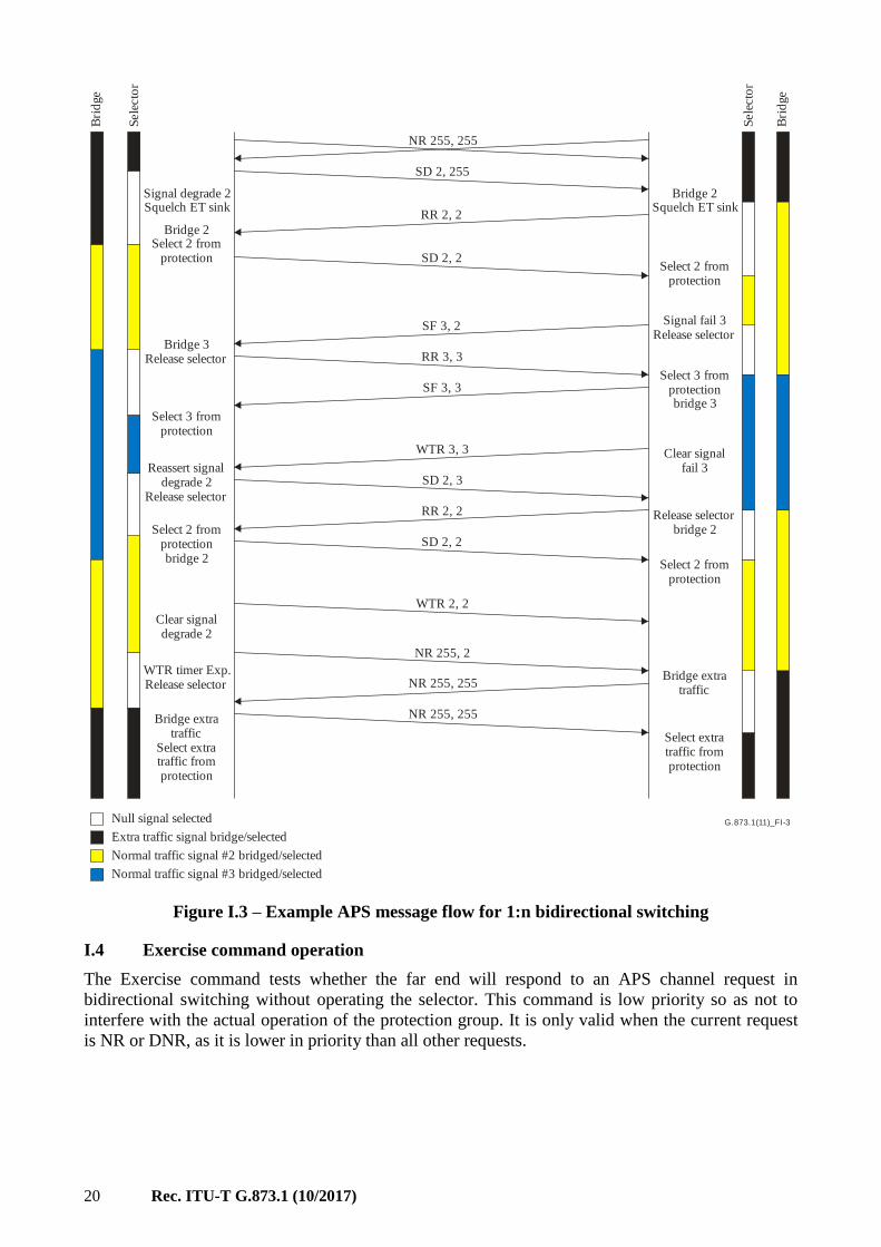
I.3 1:n bidirectional switching
Figure I.3 shows an example of 1:n bidirectional switching with extra traffic. What is illustrated is
the case where an SD on working #2 is pre-empted by an SF on working #3.
20 Rec. ITU-T G.873.1 (10/2017)
G.873.1(11)_FI-3
NR 255, 255
SD 2, 255
RR 2, 2
SD 2, 2
SF 3, 2
RR 3, 3
WTR 3, 3
SD 2, 3
Bridge 2Squelch ET sink
Signal fail 3Release selector
Select 3 fromprotectionbridge 3
Normal traffic signal #2 bridged/selected
Null signal selected
Bridge 3Release selector
Signal degrade 2Squelch ET sink
Sele
cto
r
Bri
dge
Sele
cto
r
Bri
dge
SF 3, 3
RR 2, 2
SD 2, 2
WTR 2, 2
NR 255, 2
NR 255, 255
NR 255, 255
Select 2 fromprotection
Clear signalfail 3
Release selectorbridge 2
Select 2 fromprotection
Bridge extratraffic
Select extratraffic fromprotection
Bridge 2Select 2 from
protection
Select 3 fromprotection
Select 2 fromprotectionbridge 2
Reassert signaldegrade 2
Release selector
Clear signaldegrade 2
WTR timer Exp.Release selector
Bridge extratraffic
Select extratraffic fromprotection
Extra traffic signal bridge/selected
Normal traffic signal #3 bridged/selected
Figure I.3 – Example APS message flow for 1:n bidirectional switching
I.4 Exercise command operation
The Exercise command tests whether the far end will respond to an APS channel request in
bidirectional switching without operating the selector. This command is low priority so as not to
interfere with the actual operation of the protection group. It is only valid when the current request
is NR or DNR, as it is lower in priority than all other requests.

Rec. ITU-T G.873.1 (10/2017) 21
Figures I.4, I.5, I.6 and I.7 give examples of operation of the Exercise command. In all cases,
neither the requested nor the bridged entity numbers are changed for the Exercise command. A
successful response is receiving an "RR" with the same entity number. Note that having DNR
answered with DNR provides a way to test that the Exercise command receives the appropriate RR
response.
G.873.1(11)_FI-4
NR 0, 1
EX 0, 1
RR 0, 1
NR 0, 1
NR 0, 1
ReplyExercice
command
ReplyClear exercice
command
Figure I.4 – Example of Exercise command from 1+1 NR state
G.873.1(11)_FI-5
DNR 1, 1
EX 1, 1
RR 1, 1
DNR 1, 1
DNR 1, 1
ReplyExercice
command
ReplyClear exercice
command
Figure I.5 – Example of Exercise command from 1+1 DNR state

22 Rec. ITU-T G.873.1 (10/2017)
G.873.1(11)_FI-6
NR 0, 0
EX 0, 0
RR 0, 0
NR 0, 0
NR 0, 0
ReplyExercice
command
ReplyClear exercice
command
Figure I.6 – Example of Exercise command from 1:n NR state
without extra traffic
G.873.1(11)_FI-7
NR 255, 255
EX 255, 255
RR 255, 255
NR 255, 255
NR 255, 255
ReplyExercice
command
ReplyClear exercice
command
Figure I.7 – Example of Exercise command from 1:n NR state
with extra traffic

Rec. ITU-T G.873.1 (10/2017) 23
Appendix II
ODUk client protection
(This appendix does not form an integral part of this Recommendation.)
II.1 Overview over protection architectures of OTN linear client protection
Table II.1 provides an overview of the linear OTN client protection types which are supported by
the description in this appendix.
Table II.1 – Overview of linear OTN client protection architectures and related monitoring
Protection
architec-
ture
Switching
type
Protection
subclass
and
monitoring
ODU entities
for
protection
switching,
individual/
group
APS
channel
used and
MFAS in
bits 6-8
Server
layer of
protected
entity
Protection
switched
entity
Trigger
criteria
used
1+1 Unidir SNC/Nc Individual No One or
more HO
ODUk
and/or
OTUk
LO LO ODU
TSF/TSD + LO
OPU-CSF
1+1 Unidir SNC/I Individual No One LO
ODUk
Client Client_CI_CSF
Client_CI_SSD
1+1 Bidir SNC/I Individual LO 000 One LO
ODUk
Client Client_CI_CSF
Client_CI_SSD
1:1 Bidir SNC/I Individual LO 000 One LO
ODUk
Client Client_CI_CSF
Client_CI_SSD
II.2 Model of client SNC/Nc protection architecture of OTN linear client protection
Figure II.1 provides the model overview of the client SNC/Nc scheme as listed in Table II.1. The
protection uses the ODU connection function and the CI_SSF CI_CSF information of the ODU
NIM OTN as input to the protection. This is a special version of the 1+1 ODUk SNC/N protection
method in which the status of the incoming client signal as encoded in the client signal fail (CSF)
indication of the optical payload unit (OPU) is used as an additional signal fail condition.
Monitoring method
Non-intrusive with client fail – Protection switching is triggered by a non-intrusive monitor of the
ODUkP trail and OPUk-CSF at the tail-end of the protection group.
NOTE – This monitoring type is also intended to support protection switching in dual-root 1+1 p2mp,
unidirectional switched SNC/Nc protected ODUk connections, which are deployed in content distribution
applications.
Protection architecture
Dual-root 1+1 – In a dual-root 1+1 architecture, two unidirectional client signals with the same
content, typically applied at different locations to the OTN, are protected. One of the client signals
is carried in a working ODUk connection and the other client signal is carried in a protection ODUk
connection. Switching occurs entirely at the tail-end by monitoring the ODUk and OPUk.

24 Rec. ITU-T G.873.1 (10/2017)
G.873.1(11)_FII-1
Normal (protected)ODUk CP
ODUk
SF SFSD SD
OD
Uk
P/C
lien
t
OD
Uk
P/C
lien
t
OD
Uk
P
OD
Uk
P
SSF SSF
WorkingODUk CP
ProtectionODUk CP
ODUkT/ODUkOTUk[V]/ODUkODUkP/ODU[j]j
ODUkT/ODUkOTUk[V]/ODUkODUkP/ODU[j]j
Figure II.1 SNC/Nc protection atomic functions
Figure II.1 gives the atomic functions involved in SNC/Nc protection. The working and protection
ODU_CI coming from either an OTUk[V]/ODUk_A or ODUkT/ODUk_A or ODUkP/ODUj_A
function are monitored by a ODUkP and ODUkP/Client non-intrusive monitor, which provide the
SF and SD protection switching criteria. The protection may rely on a particular ODUk/Client
adaptation source function which is capable to activate OPUk-CSF under failure of the client signal,
as for example a ODU0P/ETC3_A_So function which could be capable to activate OPU0-CSF
under failure of the 1GE content stream.
II.3 Model of client SNC/I protection architectures of OTN linear client protection
Figure II.2 provides the model overview of the client SNC/I schemes as listed in Table II.1. The
protection uses the client connection function external to the OTN and the OPU-CSF transport of
the OTN as input to the protection.
SNC/I client protection requires that the client signal be split between two different ports in the
client-to-network direction. Each port maps the client into an ODUk and the two ODUk are carried
across the OTN as if they were unrelated, unprotected signals. At the far end, the two ODUks are
each terminated and the client signals are recovered. One or the other client signal is transmitted,
based on monitoring of the ODUk overhead (including OPU-CSF). Two different selection
mechanisms are possible, as shown in Figure II.2. Option (a) uses a Y-cable and a control process
that monitors the ODUkP trail termination functions to determine which one provides the better
signal and controls the client termination function (srv_TT) such that only one of the two
transmitters is active. Option (b) uses an external optical switch with a selector that is controlled by
the ODUkP trail termination functions. The client's APS information is transported over the ODUk
PM APS channel. Access to this channel is provided via an extended version of the ODUkP/CBR
adaptation functions specified in [ITU-T G.798]. The extension contains support for ODUk PM
APS insertion and extraction processes as illustrated in Figures II.3 and II.4.

Rec. ITU-T G.873.1 (10/2017) 25
G.873.1(11)_FII-2
OTUk/ODUkODUkT/ODUkODUkP/ODUj
OTUk/ODUkODUkT/ODUkODUkP/ODUj
OTUk/ODUkODUkT/ODUkODUkP/ODUj
OTUk/ODUkODUkT/ODUkODUkP/ODUj
ODU ODU
ODUk ODUk
ODUk/client ODUk/client
srv/client srv/clientsrv/client srv/client
srv srvsrv srv
ODUk/client ODUk/client
ODUk ODUk
Controlprocess
Controlprocess
Y- cableOptical switch
a) Y-cable implementation b) optical switch implementation
Figure II.2 – OTN client SNC/I protection models
G.873.1(14)_FII.3
CSF
PT
PMAPS
AI_D AI_CK AI_FS AI_MFS
ODUkP_AP
ODUk OH is set to all-ZEROs,except PM STAT = 001
RES
CI_APS
CI_CSF
Figure II.3 – Supporting ODUk PM APS access in ODUkP/CBR
adaptation source functions

26 Rec. ITU-T G.873.1 (10/2017)
G.873.1(14)_FII.4
Extract PMAPS
Extract CSF
AI_D AI_CK AI_FS AI_TSFAI_MFS
ODUkP_AP
Extract PT
MI_
AcP
T
PT process
dPLMdCSF
CI_
AP
S
Figure II.4 – Supporting ODUk PM APS access in ODUkP/CBR
adaptation sink functions

Rec. ITU-T G.873.1 (10/2017) 27
Appendix III
Media layer protection
(This appendix does not form an integral part of this Recommendation.)
III.1 Overview of media layer protection
Protection of the media layer can be provided for as OTS maintenance entity, OMS maintenance
entity, OTSi or directly on the fibre through the use of a media element that includes an optical
switch and the use of trail protection for the non-associated overhead (if present). The location of
the optical switch within the media element and which elements of non-associated overhead are
protected determines which type of protection is provided by a particular implementation.
This appendix describes the corresponding media layer protection schemes.
III.2 Media layer protection types
The OTS and OMS media link has been defined in clause 8.4 of [b-ITU-T G.872] and the context is
shown in Figure III.1 as an example of a network with OTS and OMS OSME.
Figure III.1 – Network with OTS and OMS optical signal maintenance entities (OSME)
OTS OSME protection
A protected OTS OSME can be provided between two nodes. In this case there is a separate OSC
channel for the working and protection links and there may optionally be redundant amplifiers.
Trail protection is used for the OTS-O sublayer. The optical switch and OTS-O trail protection are
coordinated such that they switch together. This is shown in Figure III.2.

28 Rec. ITU-T G.873.1 (10/2017)
Figure III.2 – OTS OSME protection
OMS OSME protection
A protected OMS maintenance entity can be provided between two nodes. In this case there is a
separate OSC channel for the working and protect links, the media element has separate amplifiers
for each link and there is a separate OTS-O overhead for each link. Trail protection is used for the
OMS-O sublayer. The optical switch and OMS-O trail protection are coordinated such that they
switch together. This is shown in Figure III.3.

Rec. ITU-T G.873.1 (10/2017) 29
Figure III.3 – OMS OSME protection
Individual OTSi(G) protection
An optical switch (or set of such switches) can be used to protect an individual OTSi (or the set that
comprise an OTSiG) prior to optical multiplexing. In this case there are separate OMS-O trails for
each of the links and the OTSiG-O is protected. In the interest of maintaining continuity with the
old model (which describes OCh SNC protection in substantial detail in [ITU-T G.798]), individual
OTSi protection can be modelled as OCh or OTSi SNC protection, with the understanding that both
an "optical connection" (i.e., appropriate media channels) and an overhead connection need to be
configured and switched. This is shown in Figure III.4.

30 Rec. ITU-T G.873.1 (10/2017)
Figure III.4 – OCh or OTSi SNC protection
Media protection below the OSC filter
In this case there is no overhead part of the protection since the OSC has not yet been terminated.
Figure III.5 shows media protection below the OSC filter.

Rec. ITU-T G.873.1 (10/2017) 31
Figure III.5 – Media protection below the OSC filter

32 Rec. ITU-T G.873.1 (10/2017)
Bibliography
[b-ITU-T G.805] Recommendation ITU-T G.805 (2000), Generic functional architecture of
transport networks.
[b-ITU-T G.841] Recommendation ITU-T G.841 (1998), Types and characteristics of SDH
network protection architectures.
[b-ITU-T G.872] Recommendation ITU-T G.872 (2017), Architecture of optical transport
networks.


Printed in Switzerland Geneva, 2017
SERIES OF ITU-T RECOMMENDATIONS
Series A Organization of the work of ITU-T
Series D Tariff and accounting principles and international telecommunication/ICT economic and
policy issues
Series E Overall network operation, telephone service, service operation and human factors
Series F Non-telephone telecommunication services
Series G Transmission systems and media, digital systems and networks
Series H Audiovisual and multimedia systems
Series I Integrated services digital network
Series J Cable networks and transmission of television, sound programme and other multimedia
signals
Series K Protection against interference
Series L Environment and ICTs, climate change, e-waste, energy efficiency; construction, installation
and protection of cables and other elements of outside plant
Series M Telecommunication management, including TMN and network maintenance
Series N Maintenance: international sound programme and television transmission circuits
Series O Specifications of measuring equipment
Series P Telephone transmission quality, telephone installations, local line networks
Series Q Switching and signalling, and associated measurements and tests
Series R Telegraph transmission
Series S Telegraph services terminal equipment
Series T Terminals for telematic services
Series U Telegraph switching
Series V Data communication over the telephone network
Series X Data networks, open system communications and security
Series Y Global information infrastructure, Internet protocol aspects, next-generation networks,
Internet of Things and smart cities
Series Z Languages and general software aspects for telecommunication systems