Embed Size (px)
Citation preview

I n t e r n a t i o n a l T e l e c o m m u n i c a t i o n U n i o n
ITU-T G.100.1 TELECOMMUNICATION STANDARDIZATION SECTOR OF ITU
(06/2015)
SERIES G: TRANSMISSION SYSTEMS AND MEDIA, DIGITAL SYSTEMS AND NETWORKS
International telephone connections and circuits – Transmission planning and the E-model
The use of the decibel and of relative levels in speechband telecommunications
Recommendation ITU-T G.100.1

ITU-T G-SERIES RECOMMENDATIONS
TRANSMISSION SYSTEMS AND MEDIA, DIGITAL SYSTEMS AND NETWORKS
INTERNATIONAL TELEPHONE CONNECTIONS AND CIRCUITS G.100–G.199
Transmission planning and the E-model G.100–G.109
General Recommendations on the transmission quality for an entire international telephone connection
G.110–G.119
General characteristics of national systems forming part of international connections G.120–G.129
General characteristics of the 4-wire chain formed by the international circuits and national extension circuits
G.130–G.139
General characteristics of the 4-wire chain of international circuits; international transit G.140–G.149
General characteristics of international telephone circuits and national extension circuits G.150–G.159
Apparatus associated with long-distance telephone circuits G.160–G.169
Transmission plan aspects of special circuits and connections using the international telephone connection network
G.170–G.179
Protection and restoration of transmission systems G.180–G.189
Software tools for transmission systems G.190–G.199
GENERAL CHARACTERISTICS COMMON TO ALL ANALOGUE CARRIER-TRANSMISSION SYSTEMS
G.200–G.299
INDIVIDUAL CHARACTERISTICS OF INTERNATIONAL CARRIER TELEPHONE SYSTEMS ON METALLIC LINES
G.300–G.399
GENERAL CHARACTERISTICS OF INTERNATIONAL CARRIER TELEPHONE SYSTEMS ON RADIO-RELAY OR SATELLITE LINKS AND INTERCONNECTION WITH METALLIC LINES
G.400–G.449
COORDINATION OF RADIOTELEPHONY AND LINE TELEPHONY G.450–G.499
TRANSMISSION MEDIA AND OPTICAL SYSTEMS CHARACTERISTICS G.600–G.699
DIGITAL TERMINAL EQUIPMENTS G.700–G.799
DIGITAL NETWORKS G.800–G.899
DIGITAL SECTIONS AND DIGITAL LINE SYSTEM G.900–G.999
MULTIMEDIA QUALITY OF SERVICE AND PERFORMANCE – GENERIC AND USER-RELATED ASPECTS
G.1000–G.1999
TRANSMISSION MEDIA CHARACTERISTICS G.6000–G.6999
DATA OVER TRANSPORT – GENERIC ASPECTS G.7000–G.7999
PACKET OVER TRANSPORT ASPECTS G.8000–G.8999
ACCESS NETWORKS G.9000–G.9999
For further details, please refer to the list of ITU-T Recommendations.

Rec. ITU-T G.100.1 (06/2015) i
Recommendation ITU-T G.100.1
The use of the decibel and of relative levels
in speechband telecommunications
Summary
Recommendation ITU-T G.100.1 provides the definition for different logarithmic power level
measurement units in current use in telecommunication systems. This Recommendation also provides
the relationship amongst those units and usage examples. The text herein is a merger of information
that has been previously dispersed over several publications and supersedes the contents of:
Recommendation ITU-T B.12, Annex A of Recommendation ITU-T G.100, Annex A of
Recommendation ITU-T G.101, Annex B of Recommendation ITU-T Q.551, and clause 3.8 of
Recommendation ITU-T G.101.
History
Edition Recommendation Approval Study Group Unique ID*
1.0 ITU-T G.100.1 2001-11-29 12 11.1002/1000/5596
2.0 ITU-T G.100.1 2015-06-29 12 11.1002/1000/12504
____________________
* To access the Recommendation, type the URL http://handle.itu.int/ in the address field of your web
browser, followed by the Recommendation's unique ID. For example, http://handle.itu.int/11.1002/1000/11
830-en.

ii Rec. ITU-T G.100.1 (06/2015)
FOREWORD
The International Telecommunication Union (ITU) is the United Nations specialized agency in the field of
telecommunications, information and communication technologies (ICTs). The ITU Telecommunication
Standardization Sector (ITU-T) is a permanent organ of ITU. ITU-T is responsible for studying technical,
operating and tariff questions and issuing Recommendations on them with a view to standardizing
telecommunications on a worldwide basis.
The World Telecommunication Standardization Assembly (WTSA), which meets every four years, establishes
the topics for study by the ITU-T study groups which, in turn, produce Recommendations on these topics.
The approval of ITU-T Recommendations is covered by the procedure laid down in WTSA Resolution 1.
In some areas of information technology which fall within ITU-T's purview, the necessary standards are
prepared on a collaborative basis with ISO and IEC.
NOTE
In this Recommendation, the expression "Administration" is used for conciseness to indicate both a
telecommunication administration and a recognized operating agency.
Compliance with this Recommendation is voluntary. However, the Recommendation may contain certain
mandatory provisions (to ensure, e.g., interoperability or applicability) and compliance with the
Recommendation is achieved when all of these mandatory provisions are met. The words "shall" or some other
obligatory language such as "must" and the negative equivalents are used to express requirements. The use of
such words does not suggest that compliance with the Recommendation is required of any party.
INTELLECTUAL PROPERTY RIGHTS
ITU draws attention to the possibility that the practice or implementation of this Recommendation may involve
the use of a claimed Intellectual Property Right. ITU takes no position concerning the evidence, validity or
applicability of claimed Intellectual Property Rights, whether asserted by ITU members or others outside of
the Recommendation development process.
As of the date of approval of this Recommendation, ITU had not received notice of intellectual property,
protected by patents, which may be required to implement this Recommendation. However, implementers are
cautioned that this may not represent the latest information and are therefore strongly urged to consult the TSB
patent database at http://www.itu.int/ITU-T/ipr/.
ITU 2015
All rights reserved. No part of this publication may be reproduced, by any means whatsoever, without the prior
written permission of ITU.

Rec. ITU-T G.100.1 (06/2015) iii
Table of Contents
Page
1 Scope ............................................................................................................................. 1
2 References ..................................................................................................................... 1
3 Definitions .................................................................................................................... 2
3.1 Terms defined elsewhere ................................................................................ 2
3.2 Terms defined in this Recommendation ......................................................... 2
4 Abbreviations and acronyms ........................................................................................ 2
5 Conventions .................................................................................................................. 2
6 Fundamentals about dB ................................................................................................ 2
6.1 Loss and gain .................................................................................................. 3
6.2 The letter "p" in "dBmp" and "dBm0p" ......................................................... 5
6.3 Correction factors ........................................................................................... 5
6.4 Signal-to-noise ratio ....................................................................................... 7
6.5 Sound pressure level ....................................................................................... 7
7 The use of a reference signal ........................................................................................ 7
8 Relationships between the units "dBm","dBr" and "dBm0" ........................................ 9
8.1 General ........................................................................................................... 9
8.2 The unit "dB" .................................................................................................. 10
8.3 The unit "dBm" ............................................................................................... 10
8.4 The unit "dBr" ................................................................................................ 11
8.5 The unit "dBm0" ............................................................................................. 12
8.6 The relationship between dBm, dBr and dBm0 ............................................. 13
8.7 The unit "dBov" .............................................................................................. 13
8.8 Relationship between overload (dBov) and maximum levels (dBm0) .......... 14
9 The concept of "relative levels" .................................................................................... 15
9.1 General principles ........................................................................................... 15
9.2 Circuits and connections ................................................................................. 16
9.3 The speech signal and the dynamic range of the voice channel ..................... 17
9.4 Relative level designations for a digital path ................................................. 20
9.5 Relative levels in equipment design, specification and testing ...................... 21
9.6 Relative levels in transmission planning and maintenance ............................ 24
Appendix I – The neper ........................................................................................................... 27
I.1 Introduction .................................................................................................... 27
I.2 Definition of the neper .................................................................................... 27
I.3 Use of the decibel and of the neper ................................................................ 27
Bibliography............................................................................................................................. 28

Rec. ITU-T G.100.1 (06/2015) 1
Recommendation ITU-T G.100.1
The use of the decibel and of relative levels
in speechband telecommunications
1 Scope
In transmission engineering, most often it would be rather impractical to characterize the magnitude
of signals directly by a numerical value in volts or watts. Instead, a logarithmic measure is used,
expressed in "dB", to characterize the signal magnitude in relation to some chosen reference value.
Designations commonly used are "power level difference", "voltage level difference", etc., all
expressed in "dB". A level difference from a standard situation is described simply as "level". Loss
and gain are also measured in "dB".
The term "relative levels" has been a very useful term in transmission planning for the last 40 years
and is expected to be so in the future. However, the public switched telephone networks have changed
considerably in these years. Especially with the introduction of digital exchanges which causes some
uncertainty concerning the application of relative levels and necessitates some changes in the
traditional way of applying relative levels. In this Recommendation, relative levels and associated
terms are explained and examples are shown to clarify these concepts.
Guidance on the use of decibels in the field of sound transmission and radio frequencies can be found
in [ITU-R V.574-4].
Notations for expressing the reference of a level can be found in Part 5 of [IEC 60027-3].
2 References
The following ITU-T Recommendations and other references contain provisions which, through
reference in this text, constitute provisions of this Recommendation. At the time of publication, the
editions indicated were valid. All Recommendations and other references are subject to revision;
users of this Recommendation are therefore encouraged to investigate the possibility of applying the
most recent edition of the Recommendations and other references listed below. A list of the currently
valid ITU-T Recommendations is regularly published. The reference to a document within this
Recommendation does not give it, as a stand-alone document, the status of a Recommendation.
[ITU-T G.111] Recommendation ITU-T G.111 (1993), Loudness ratings (LRs) in an
international connection.
[ITU-T G.121] Recommendation ITU-T G.121 (1993), Loudness ratings (LRs) of national
systems.
[ITU-T G.223] Recommendation ITU-T G.223 (1988), Assumptions for the calculation of
noise on hypothetical reference circuits for telephony.
[ITU-T G.711] Recommendation ITU-T G.711 (1988), Pulse code modulation (PCM) of voice
frequencies.
[ITU-T G.712] Recommendation ITU-T G.712 (2001), Transmission performance
characteristics of pulse code modulation channels.
[ITU-T G.722] Recommendation ITU-T G.722 (2012), 7 kHz audio-coding within 64 kbit/s.
[ITU-T O.41] Recommendation ITU-T O.41 (1994), Psophometer for use on telephone-type
circuits.
[ITU-T P.56] Recommendation ITU-T P.56 (2011), Objective measurement of active speech
level.

2 Rec. ITU-T G.100.1 (06/2015)
[ITU-T P.79] Recommendation ITU-T P.79 (2007), Calculation of loudness ratings for
telephone sets.
[ITU-R V.574-4] Recommendation ITU-R V.574-4 (2000), Use of the decibel and the neper in
telecommunications.
[IEC 60027-3] IEC 60027-3:2002, Letter symbols to be used in electrical technology – Part 3:
Logarithmic and related quantities, and their units.
[IEC 60651] IEC 60651:1979, Sound level meters.
3 Definitions
3.1 Terms defined elsewhere
None.
3.2 Terms defined in this Recommendation
None.
4 Abbreviations and acronyms
This Recommendation uses the following abbreviations and acronyms:
CLR Circuit Loudness Rating
DRS Digital Reference Sequence
FDM Frequency Division Multiplexing
LR Loudness Rating
MNRU Modulated Noise Reference Unit
PBX Private Branch exchange
PCM Pulse Code Modulation
RLR Receive Loudness Rating
RMS Root Mean Square
SPL Sound Pressure Level
SLR Send Loudness Rating
TRP Transmission Reference Point
5 Conventions
None.
6 Fundamentals about dB
The bel (symbol B) expresses the ratio of two powers by the decimal logarithm of this ratio. This unit
is not often used, having been replaced by the decibel (symbol dB), which is one-tenth of a bel.
The decibel may be used to express the ratio of two field quantities, such as voltage, current, sound
pressure, electric field, charge velocity or density, the square of which in linear systems is
proportional to power. To obtain the same numerical value as a power ratio, the logarithm of the field
quantity ratio is multiplied by the factor 20, assuming that the impedances are equal.

Rec. ITU-T G.100.1 (06/2015) 3
The relationship between a current or voltage ratio and that of the corresponding power ratio is
impedance dependent. Use of the decibel when the impedances are not equal is not appropriate unless
adequate information is given concerning the impedances involved.
The "dB" is a very practical unit which can be used in many different applications.
Comparing two signal powers P1 mVA and P2 mVA, P1 is said to be at an L dB higher (power) level
than P2, where
dB log 10 L2
1
P
P (6-1)
Comparing two voltages, V1 volts and V2 volts, V1 is said to be at an L dB higher (voltage) level than
V2, where
dB log 20 L2
1
V
V (6-2)
Note that "power" depends on the square of "voltage", hence the coefficient 10 in equation (6-1) and
the coefficient 20 in equation (6-2).
Equation (6-2) is also used for quantities other than volts, for instance, currents, acoustic pressure,
etc. Note that the term (V1/V2) must be a dimensionless quantity. This is automatically fulfilled when
V1 and V2 represent two amplitudes of the same kind. Otherwise, V1 and V2 must each be referred to
specific reference values of the proper dimension. (For instance, the send sensitivity of a telephone
set is described as the relationship between the input pressure in Pascal and the output voltage in
volts, expressed as "dB rel. 1V/Pa".)
6.1 Loss and gain
The unit dB is also used to characterize loss or gain (of power or voltage) in a system.
Figure 1 shows how a voltage loss may be defined and calculated. The voltage loss is equal to the
voltage level difference between port a) and port b).
Figure 1 – Example of voltage loss from port a) to port b)
A special case is the return loss Ar which gives a measure of the mismatch between two impedances
Z1 and Z2. (Ar can be described as the voltage loss between the incident and the reflected signal at the
point of mismatch.) The expression for Ar is:
dB log2021
21
ZZ
ZZAr
(6-3)
For passive, reciprocal two-ports (like analogue, passive filters) it has been found practical to base
the loss concept on the power level difference between the so-called apparent powers at the input and
the output of the two-port. (It can be shown that for such types of circuits this definition of loss results
in the same loss for both directions of transmission.)
Figure 2 depicts the configuration.

4 Rec. ITU-T G.100.1 (06/2015)
Figure 2 – Example for apparent power loss calculation
Note that the signal generator in Figure 2 produces a single-frequency tone.
The reference apparent power P1 from the generator is defined to be obtained when the load is equal
to the generator impedance Z1. With the designation P2 for the output apparent power we get:
1
2
1Z
EP
2
2
2Z
VP (6-4)
Thus, the (apparent power) loss is:
dB log20dB log102
1
2
1
V
E
Z
Z
P
PA (6-5)
However, in telephone networks the transmission chain consists of cascaded units which contain
amplifiers and 4-wire loops which are non-reciprocal and therefore the loss concept in equation (6-5)
needs some modification in order to remain practical.
As long as the impedances Z1 and Z2 are real and constant with frequency, equation (6-5) is still used
as a definition of loss. "Apparent power" (expressed in mVA) is in this case equal to "active power"
(expressed in mW).
When one or both of the impedances are complex and varying with frequency, the transfer of
"apparent power" at different frequencies is not an adequate measure of circuit performance. One of
the reasons why is that the active components in the chain react on input voltage, not on apparent
power.
Therefore, a circuit in accordance with Figure 2 is defined as having a flat frequency response when
constant log20 V
E (6-6)
irrespective of how the (given) impedances Z1 and Z2 vary with frequency.
To retain the coupling to the power concept, the nominal loss A0 is defined as the apparent power loss
at a reference frequency F0 1020 Hz as follows:
dB log2001
02
0
00
FZ
FZ
FV
FEA (6-7)
Thus, the frequency-dependent loss of a circuit in accordance with Figure 2 is defined as:
dB log2001
02
FZ
FZ
fV
fEfA (6-8)
The losses of cascaded units can be added to get the total overall loss of the chain provided the
impedance mismatching at the interconnection points is reasonably small.
NOTE 1 – These loss definitions also apply for electro-acoustic parameters, such as telephone set sensitivities.
In this case, however, for the send characteristics the input voltage in volts is divided by the output sound

Rec. ITU-T G.100.1 (06/2015) 5
pressure in Pascal and vice versa for the receive characteristics. (Corrections are to be applied if the nominal
impedance is not 600 ohms.)
NOTE 2 – The concept of apparent power at a frequency different from the reference frequency of 1020 Hz is
irrelevant.
NOTE 3 – The receive characteristic of a telephone set is usually rather flat with frequency within the
transmitted speech band. The send characteristic often has a pronounced pre-emphasis at the high end of the
frequency band.
6.2 The letter "p" in "dBmp" and "dBm0p"
The additional small letter "p" is derived from the French word "ponderé" for "weighted" and means
that the considered value is a noise level, measured by a psophometer with a special noise weighting
filter included as described in [ITU-T O.41].
6.3 Correction factors
Depending on the type of test instruments, auxiliary equipment and test objects, sometimes correction
factors need to be used, to either adjust the correct test signal level, or to obtain the correct test result.
This mainly occurs in conjunction with capacitive complex impedances.
In practice, test instruments may be used with input/output impedances of only 600 resistive and
consequently send levels or displayed results referred to 1 mW. To provide the correct termination of
test objects with complex impedances, auxiliary devices called "impedance converters" are used. The
principle of such an impedance converter is shown in Figure 3 in the application for sending and in
Figure 4 for receiving.
Figure 3 – Impedance converter in the sending path
Figure 4 – Impedance converter in the receive path

6 Rec. ITU-T G.100.1 (06/2015)
An advantageous design is to obtain a power transfer ratio of 1 at the reference frequency of 1020 Hz,
if terminated with the respective nominal impedances at input and output. In this case the voltage
gain "s" of the inserted amplifier is:
dB log106in
out
Z
Zs (6-9)
This formula is valid for the send and receive parts of an impedance converter. It should be noted,
that if Zout or Zin is a complex impedance, the modulus at the reference frequency of 1020 Hz has to
be used.
For impedance converters in the application with different complex impedances the gain "s" is
normally only adjusted to 6 dB (power transfer ratio 1 only, if Zin = Zout) and correction values are
used as shown in clauses 6.3.1 and 6.3.2.
6.3.1 Sending a test signal
In this application (see Figure 3) Zin is exactly matched to the impedance Zi of the signal generator
(e.g., 600 ) and Zout is the nominal value of the interface impedance ZPBX of the private branch
exchange (PBX) under test.
To obtain the required test level LT in dBm0 at the IMP, the necessary send level LS in dBm of the
signal generator can be calculated as follows:
in
outiTS
Z
ZLLL log10dBr dBm0 dBm (6-10)
Example 1: For an interface of the PBX under test with an input relative level Li = –5 dBr and a
nominal impedance ZPBX = 842 (modulus at 1020 Hz for a 3-element complex impedance with
270 + 750 // 150 nF) a test level of LT = –10 dBm0 shall be provided. What is the necessary send
level LS in dBm at a signal generator with 600 impedance? Applying equation (6-10) the following
result for LS is obtained:
600
842log10dBr 5dBm0 10 SL
dBm 53.13SL
6.3.2 Receiving a test signal
For receiving (see Figure 4), Zout is exactly matched to the instrument impedance Zi and Zin provides
the nominal termination of the IUT with the impedance ZPBX.
To obtain the correct (received) test level LT in dBm0 at the IMP, the displayed receive level LR
in dBm at the signal receiver needs to be corrected, using the following formula:
in
outoRT
Z
ZLLL log10dBrdBmdBm0 (6-11)
Example 2: Assuming the same impedances for the test instrument (600 ) and the PBX under test
(842 ) as in example 1, but with an output relative level of Lo = –7 dBr, what is the correct received
test level LT if the signal receiver readout is LR = –50 dBm? Applying equation (6-11) the following
result for LT is obtained:
842
600log10dBr 7dBm 50 TL
dBm0 47.44TL

Rec. ITU-T G.100.1 (06/2015) 7
6.4 Signal-to-noise ratio
The signal-to-noise ratio can be either the ratio of the signal power (PS) to the noise power (PN), or
the ratio of the signal voltage (US) to the noise voltage (UN) measured at a given point with specified
conditions. It is expressed in decibels:
dB log20or dB log10
N
S
N
S
U
UR
P
PR (6-12)
The ratio of the wanted signal to the unwanted signal is expressed in the same way.
6.5 Sound pressure level
The sound pressure level (SPL) is the logarithm, generally expressed in decibels, of the ratio of sound
pressure and a reference pressure, often 20 Pa but typically referenced to 1 Pa in telephonometry.
Usually the sound pressure when referenced to 20 µPa is called dBSPL.
Example:
15 dB(20 µPa) or 15 dBSPL
As acoustic power is linked to the square of sound pressure, this means:
20 log (p / 20 µPa) =15 dB(20 Pa)
In the ratio (p/20 µPa) or (p/1 Pa), it is evident that both sound pressures must be expressed in the
same units.
Often the sound pressure level is weighted in order to take into account the human ear sensitivity in
frequency. For the absolute acoustic pressure level, dBSPL(A) (or dBSPL(B), dBSPL(C)) refers to the
weighted acoustic pressure level with respect to 20 µPa, mentioning the weighting curve used (curves
A, B or C, see [IEC 60651]). The same weighting can also be applied when referring the sound
pressure to 1 Pa (e.g., dBPa(A)).
7 The use of a reference signal
The concept of a "reference signal" sent through the network is very useful to visualize the signal
transmission in general.
In the analogue parts of the network, the defined reference signal is a tone of the frequency 1020 Hz,
the reference frequency F0. Its magnitude is determined in such a way that it would have an apparent
power value of 1 mVA at a certain level reference point. (Note that instead of mVA, the ITU-T has
traditionally used the designation "mW".)
A level reference point may exist physically or only fictitiously. How it is located within an item of
equipment or a circuit is discussed in clause 9.
In general a level reference point in the analogue part of the network has a complex nominal
impedance Zn whose modulus |Zn| varies with frequency. Thus, in this reference point, the voltage of
the reference signal is:
V 001.0 00 FZFV n (7-1)
Ω 0FZn
NOTE – In earlier systems, the nominal impedance at an analogue level reference point was always resistive
and constant with frequency. However, the modern trend is to use complex impedances in the 2-wire parts of
the network.
The reference signal is said to have an absolute level of 0 dBm at the level reference point. (Note that
actual test signals most often are specified at levels 10 dB lower than this reference signal.)

8 Rec. ITU-T G.100.1 (06/2015)
In a digital path the reference signal corresponds to a special case of the pulse code modulation (PCM)
digital reference sequence, namely the digital reference sequence (DRS), with the frequency of 1020
Hz.
The unit dBm is also used to characterize the absolute level of a tone of a frequency which is different
from the reference frequency F0. If the absolute level of the signal is stated to be L dBm at a point of
nominal impedance Zn, the voltage is defined as:
V 10001.0 20L0 FZfV n (7-2)
Note especially that the modulus of the nominal impedance in equation (7-2) is always to be taken at
the reference frequency F0. (This is in accordance with the principle previously mentioned in
clause 6.)
How shall the magnitude of complex signals be evaluated properly (i.e., signals having a broad
spectrum instead of a single tone)?
First the case of the signal working on a resistive constant impedance will be discussed. For frequency
division multiplexing (FDM) systems, the performance is affected by the total power injected in the
channels. As the FDM voice-band channel input impedances are designed to be resistive R, the
power is determined simply by a voltage-square-average, divided by the input resistance R:
mW d001.0
12
1
2
12
fR
fV
FFP
F
F
(7-3)
where:
V(f) = spectral voltage/ Hz
R in ohms
F1, F2 in Hz, the band-limits of the signal.
The result can thus be expressed as an absolute level in dBm, i.e., in this case dB relative to an active
power of 1 mW.
dBm log10 PL (7-4)
When the dBm-value of a voice signal acting on a constant-resistance load is calculated in this way,
a fairly accurate predication can be made of many parameters, such as for instance, peak voltages and
their statistical distribution with time.
In modern voiceband equipment, such as digital exchanges, however, the signals pass interfaces with
complex nominal impedances. The transfer is made on a voltage basis as mentioned previously and
the active elements are sensitive to voltage, not power. The proper signal magnitude evaluation thus
must also be based on voltage. To retain the principles applied for the FDM case, the signal
"magnitude measure" is taken to be a voltage-square-average, but divided by the modulus of the
nominal complex impedance Zn(F0) at the reference frequency F0.
mVA d
001.0
12
10
2
12
fFZ
fV
FFP
F
F n
(7-5)
The corresponding level is given by equation (7-4).
Note that P in equation (7-5) also has the dimension of mVA or, as traditionally used in ITU-T, of
mW. Therefore, the magnitude of a complex signal sometimes is stated in mW or pW on the basis of
equation (7-5). This is quite useful for noise signals, because the pWs of uncorrelated signals can be
Rec. ITU-T G.100.1 (06/2015) 9
added to get the total pW. (Note, however, that this power concept has nothing to do with apparent
power.)
The magnitude of normal voice signals can be measured by means of special instruments. Formerly
it was the practice to use the so-called VU meter. Now, instruments in accordance with [ITU-T P.56]
are preferred, (both these types are based on voltage-square evaluation). From the instrument
readings, such properties as long- and short-time power, peak values, etc., may be determined.
When an electric signal is transformed into acoustic pressure by the telephone receiver, the human
hearing characteristics must be taken into account in order to determine the proper signal magnitude
the listener perceives. For noise signals, this is done by adding a psophometric weighting W( f ) dB,
which is specified in [ITU-T O.41]. (Note that the weighting includes the response of a "typical"
telephone receiver, pressed hard against the listener's ear, i.e., the receiver's frequency response is
quite flat within the speech band up to about 3.4 kHz, where band-limiting begins.)
The corresponding psophometric power is:
mVA d10
001.0
1 10
0
2
12
2
1
fFZ
fV
FFP fW
F
F n
(7-6)
Here, F1 16.66 Hz, F2 6000 Hz
The absolute psophometric level is designated dBmp:
dBmp log10 pp PL (7-7)
An instrument performing a psophometric weighting, including a certain time constant, is termed
"psophometer", the performance of which is specified in [ITU-T O.41].
In transmission planning it is important to know the electro-acoustic losses voice signals are subjected
to when passing through the network. These losses are termed "loudness ratings" and are also
measured in dB. Note, however, that it is not appropriate to determine loudness ratings as a difference
in readings of speech levels (volumes), using a VU-meter, a P.56-instrument or a psophometer. The
reason is that for loudness rating the signal weighting is different from the one used for speech level
evaluation. For loudness ratings the weighting depends on the voice signal level and is made over an
approximately logarithmic frequency scale (see [ITU-T P.79]).
For voice signals at normal levels the signal weighting is done approximately as a dB average. Send
loudness rating (SLR) and receive loudness rating (RLR) are measured using instruments specified
in the P-series Recommendations. The circuit loudness rating (CLR), i.e., the loudness loss a typical
circuit element like a subscriber cable introduces, is best determined by computation. Note that the
nominal loss A0 as defined by equation (6-7) turns out to be a good measure of CLR.
For weaker, voice-derived signals, the signal weighting is different. For listener's echoes it is done as
a voltage average, for talker's echoes and crosstalk as a voltage-square average. (For brevity, in this
context voltage-square additions are sometimes called power addition.)
Further information is found in Annex A of [ITU-T G.111] and in the P-series Recommendations.
8 Relationships between the units "dBm","dBr" and "dBm0"
8.1 General
Transmission values for loss, gain and levels are expressed in decibels (dB) as a general principle.
The basic unit "dB" is often extended with additional letters in order to distinguish between its use in
different applications. The aim of this clause is to give a short description of the most common forms
as used for transmission measurements at speech-band frequencies as well as an introductory

10 Rec. ITU-T G.100.1 (06/2015)
explanation of certain transmission planning applications. See clause 9 for a more complete
discussion.
8.2 The unit "dB"
This basic unit is mainly used for losses, gains, return losses, etc., i.e., as a logarithmic ratio between
two values which can be voltages, currents, powers, acoustic pressures, etc. If the ratio is X for
voltages, currents or pressures, the dB expression is 20 log (X). If the ratio is Y for powers, the dB
expression is 10 log (Y).
8.3 The unit "dBm"
This unit with an additional "m" is used as a logarithmic measure of the "magnitude" P of an actual
signal. The "dBm value" of a signal is called its "absolute power level" or "absolute level".
The signal magnitude P used for signal characterization in speech-band applications has the
dimension of power, expressed in mW or mVA, and has by definition the form:
mVAor mW )(
1000
0
2
fZ
VP
(8-1)
where:
V: the root mean square (rms) value in volts of the voltage across the test impedance
Z which in the general case is complex and frequency dependent;
Z (f0): the value of the test impedance in ohms at the (sinusoidal) reference frequency
f0 = 1020 Hz.
The choice of this definition is based on three conventions:
1) firstly, it is practical to characterize the signal magnitude by a unit that has the dimension of
power because this has been the practice for the special case of resistive terminations;
2) secondly, electronic circuits are designed to react on voltages, i.e., the open-circuit output
voltage of, for instance, an amplifier depends only upon the voltage across its input terminals,
irrespective of the input and output impedances of the amplifier. Thus, the "power" absorbed
by the input impedance of the amplifier has no influence on how the signal is amplified.
Hence the use of a constant impedance value in the denominator instead of a frequency-
dependent impedance;
3) thirdly, for a sinusoidal signal with the reference frequency (1020 Hz) the numeric value of
P shall be equal to the apparent power absorbed by Z, when this is complex, which is the
same as the active power when Z is resistive.
Note that P is equal to the active power absorbed by the test impedance Z only when the latter is
purely resistive and constant with frequency, for instance when Z = 600 . Then P is measured in
mW, otherwise P is measured in mVA. However, when Z is complex, the value of P does not
represent the apparent power absorbed by the test impedance at other frequencies than the reference
frequency of 1020 Hz.
The definition for the so-called absolute power level L is:
dBm log100P
PL (8-2)
where:
P: the power in mW to be stated;
P0: the reference value which is P0 = 1 mW.

Rec. ITU-T G.100.1 (06/2015) 11
Likewise, in the speech band the loss between two analogue points 1 and 2 is defined to be:
dB log20dB log1001
02
2
1
2
1
fZ
fZ
fV
fV
fP
fPfA (8-3)
Sometimes the unit "dBm" is used in conjunction with a voltage level, referred to a voltage of 0.775 V.
The use of "dBm" in this application is only correct if the test impedance is 600 resistive since
0.775 V across 600 results in the reference active power of 1 mW. This fact is important to
remember if capacitive complex interfaces or test impedances are used.
8.4 The unit "dBr"
This unit is used to characterize "relative levels", i.e., to express the level relations for signals between
points in a signal path, with the convention that one of the points is designated as a level reference
point with the relative level 0 dBr.
More specifically, a sinusoidal reference signal of 1020 Hz in the speech band is thought to pass the
signal path under consideration with such an amplitude that its absolute level is 0 dBm at the 0 dBr
point. The relative level in dBr at any other point in this signal path is then equal to the level (in dBm)
that the reference signal has at that point. (Note that relative level designations should be used for
both transmission directions.)
If the level reference point is digital, normally the reference signal is thought of as being decoded by
an ideal decoder at which output terminal a power of 1 mW is produced, termination 600 resistive
(see clause 8).
The relative level concept is very practical for the transmission aspects of telecommunications in
several ways. It is a method for matching the power handling capacity of the transmission equipment
in a connection to the levels of the actual signals in the network. Loss and gain in the network can be
specified by means of relative levels. In addition, relative levels can be used to characterize
parameters of certain components of the equipment.
Note however that the application rules for relative levels depend on the context in which they are
used.
It is immediately apparent that the differences of the relative levels between two points, which have
the same level reference point, correspond to the loss or gain between those two points (at the
reference frequency).
Moreover, relative levels are used to characterize the "power" handling capabilities of components
(such as codecs) and equipment on the one hand and the expected levels of actual signals in the
network on the other hand. This is discussed in more detail in the following clauses.
The "signal path under consideration", for which a specific 0 dBr reference point is designated, can
encompass:
a) a single component, such as an encoder or decoder;
b) an item of equipment, such as a half-channel of a digital exchange;
c) a circuit in the sense of the ITU-T definition, i.e., the fixed connection between two
exchanges.
In the first two cases, the "power handling capability" is the guiding principle for the allocation of a
level reference point. For the third case, the "expected absolute levels of actual signals" determines
the choice of the level reference point.
The aim is to match the component performance to the requirement for the equipment performance
which in turn should be matched to the actual range of signal levels. However, it is not always possible
to achieve this exactly. For this and other reasons, the allocation of the 0 dBr reference point in the

12 Rec. ITU-T G.100.1 (06/2015)
signal path may be chosen differently in the three cases above, i.e., when the component is considered
alone, when it is considered as part of the equipment, and when the equipment is a part of the circuit.
This means that the relative level designation for a certain point sometimes may differ in these three
cases, a fact which should be remembered when discussing relative levels.
NOTE – It would be easy to surmise that there is only one level reference point in the network to which all
relative levels are referred. However, this is not the case. As a matter of fact, in a complete connection, several
different level reference points can be designated. These may also be different from those chosen when the
parts of the transmission links are considered separately in the context of parameters for equipment or
components. Thus, when stating the relative level at a point, it should be made quite clear in which context
this relative level applies.
A more detailed discussion of the various applications of relative levels is given in clause 9.
Note that a so-called "level jump" may be introduced at the interconnection point between two
(ITU-T) circuits. Thus, the loss or gain between two points belonging to two different circuits is not
always equal to the difference in their (circuit) relative levels. Such an example is the case of the input
and output relative levels of a digital exchange having no digital loss or gain pads. When the exchange
is considered as an equipment, the difference between the (equipment) input and output relative levels
gives the loss through the exchange because the two half-channels have the same level reference
point. When the exchange is considered as a part of a connection, the two half-channels belong to
two different (ITU-T) circuits which are interconnected "in the middle of" the switching matrix. The
(circuit) input and output relative levels for the exchange, which are stated in the transmission plan
for the connection, can differ from the specified (equipment) relative levels. This is because the
(circuit) relative levels refer to two separate level reference points, each determined by estimation of
expected signal levels in the two circuits (in general, however, the differences are not very large).
For the purpose of equipment parameter specification and transmission measurement, which is of
interest here, the "power handling capability" is the governing factor for the choice of the 0 dBr level
reference point. In this context, the digital 64 kbit/s PCM bit stream is considered as having a relative
level of 0 dBr, provided that there are no digital loss or gain pads in its path. Ideal encoders and
decoders connected to the bit stream are defined as having 0 dBr relative levels at their analogue ports
when their clipping level for a sinusoidal signal lies at +3.14 dBm (A-law). The relative level for real
encoders and decoders connected to the bit stream is determined by means of the actual clipping
levels in relation to the clipping levels of the ideal codecs.
When a digital loss or gain pad is included in the digital bit stream, a choice has to be made on which
side of the pad the bit stream is to be assigned to 0 dBr. In the context of equipment specification and
transmission measurement, it has been found most practical to apply a convention that a digital bit
stream should never be assigned a higher relative level than 0 dBr. This means that:
a) a digital pad with L dB loss has the relative levels of 0 dBr at the input and –L dBr at the
output;
b) a digital pad with G dB gain has the relative levels of –G dBr at the input and 0 dBr at the
output.
Note that in the context of transmission planning, a digital bit stream sometimes may be assigned a
relative level which is different from 0 dBr even if there is no digital pad in the digital path
(see clause 9.4).
Clause 9.5.3 lists another couple of possible choices of the 0 dBr point in digital exchanges.
8.5 The unit "dBm0"
When using an additional "m" and "0" (zero) with the basic "dB", the level under consideration is
expressed as the absolute level (dBm) of the same signal that would be measured at the relevant 0 dBr
level reference point.
Rec. ITU-T G.100.1 (06/2015) 13
This term is used in conjunction with transmission measurements to specify test levels and test results;
the term also facilitates the comparison of the power levels of different signals by referring them to a
common reference point, i.e., the 0 dBr reference point. Networks are often designed to carry different
types of signals (speech, modem, fax, etc.) at different levels, expressed in dBm0.
8.6 The relationship between dBm, dBr and dBm0
The relationship between relative levels at interfaces, which have the same level reference point and
the resulting transmission loss or gain "L", is given by the formula:
oi LLL (8-4)
where Li and Lo are the relative input and output levels at the interfaces.
The relationship between the terms dBm, dBr and dBm0 can be expressed by the following formula:
dBm = dBm0 + dBr (8-5)
dBmp = dBm0p + dBr (for weighted noise) (8-6)
or:
dBm0 = dBm – dBr (general) (8-7)
dBm0p = dBmp – dBr (for weighted noise) (8-8)
Example 1: The test level for an interface with an input relative level of Li = –2 dBr, is required to be
–10 dBm0. To what absolute power level in dBm should the signal generator be adjusted?
dBm = dBm0 + dBr
= –10 + (–2) = –12 dBm
Example 2: The dial-tone level at an interface with an output relative level of Lo = –7 dBr was
measured with –19 dBm. Does this value meet the requirement given with –15 dBm0 for this type
of interface?
dBm0 = dBm – dBr
= –19 – (–7) = –12 dBm0
The result shows that the dial-tone level is outside the limit.
NOTE – Some modern test instruments also provide an automatic adjustment of the correct absolute test level,
as the necessary correction of received levels and display the results in "dBm0". In those cases the above given
calculation can be avoided; however, an additional adjustment (besides the test level itself) is required, to adapt
the test instrument to the relative input and output levels of the test object.
8.7 The unit "dBov"
In the process of specifying speech coders and other signal processing devices, it is customary to
express the codec input level specification in terms of dBs relative to the overload point of the digital
system. This is a more convenient way to represent levels relative to the maximum power that can be
stored in fixed- or floating-point format of a specific digital processing device.
In a generic notation, the overload point within the digital domain can be defined by the (normalized)
amplitude value xover = 1.0. The level specification for speech codecs is relative to this overload point
in the digital domain. It should be noted that this overload point does not depend on the quantization
method used and remains identical, regardless of whether the quantization is done e.g., with 32, 16,
13 or 8 bits. How this overload point relates to the analogue world depends on the conversion method
between the analogue and digital domains and it is beyond the scope of this Recommendation.
The power of a sampled signal x(n) with a length of N samples can be defined by:

14 Rec. ITU-T G.100.1 (06/2015)
1
0
21N
n
nxN
P
For a digital system which has an overload point xover, the maximum signal power will be P0 = 1.0.
In this case, the power level for a digital signal in decibels relative to the overload point (dBov, where
the characters "ov" arbitrarily mean digital overload signal level) is defined by:
010log10
P
PLov [dBov]
The level of the maximum signal power P0 is thus 0 dBov, which is chosen to be the reference level.
A signal with such a power level could be:
a) a sequence of maximum positive numbers (+xover);
b) a sequence of maximum negative numbers (–xover); or
c) a rectangular function exercising only the positive or negative maximum numbers (±xover).
The level of a tone with a digital amplitude (peak value) of xover is therefore L= –3.01 dBov.
8.8 Relationship between overload (dBov) and maximum levels (dBm0)
While levels in digital speech transmission networks are expressed usually in terms of the power
(expressed e.g., in dBm0), the level specification for digital processing devices such as speech coders
is specified in terms of dBov values. Hence, it is useful to relate these two level units. The conversion
between both representations can be generically expressed as:
y(dBm0) = z(dBov) + C
There are three specific cases of interest: [ITU-T G.711] for A-law, [ITU-T G.711] for µ-law and
[ITU-T G.722]. It should be noted that irrespective of the case, the level Tmax of a maximum level
tone would always be –3.01 dBov. For the ITU-T G.711 encoding rule, an encoded sequence is
provided to define the 0 dBm0 level (see Table 5 of [ITU-T G.711] for A-law and Table 6 of [ITU-T
G.711] for µ-law). The result is that a pure tone that exercises the maximum level has a power Tmax
of 3.14 dBm0 for A-law and of 3.17 dBm0 for µ-law. Therefore, C above becomes 6.15 dB for A-
law and 6.18 dB for µ-law. For the ITU-T G.722 wideband coding algorithm, the overload point of
the A/D and D/A converters is defined as +9 dBm0. Therefore, in that case, C becomes 12.01 dB.
The following relationships summarize the relationships described above:
ΛA (dBm0) = Lov (dBov) + 6.15 dB (A-law)
Λµ (dBm0) = Lov (dBov) + 6.18 dB (µ-law)
ΛG.722 (dBm0) = Lov (dBov) + 12.01 dB (ITU-T G.722)
8.8.1 Impact of interworking between codecs having unequal codec overload points
If a signal of −20 dBm0 entering a codec with +3 and +9 dBm0 codecs respectively is considered,
the following situations occur if no additional level alignment/correction is used:
Table 1 – Example of level issues that will occur if no proper level
alignment/correction is used
Encode Decode
Input level Overload point Digital level Overload point Output level Effective gain
−20 dBm0 +3 dBm0 −26 dBov +3 dBm0 −20 dBm0 0 dB
−20 dBm0 +3 dBm0 −26 dBov +9 dBm0 −14 dBm0 +6 dB

Rec. ITU-T G.100.1 (06/2015) 15
Table 1 – Example of level issues that will occur if no proper level
alignment/correction is used
Encode Decode
−20 dBm0 +9 dBm0 −32 dBov +3 dBm0 −26 dBm0 −6 dB
−20 dBm0 +9 dBm0 −32 dBov +9 dBm0 −20 dBm0 0 dB
This shows that, if no proper level alignment/correction is introduced between the codecs, there is a
6 dB electrical level shift incurred when interworking between codecs having different overload
points. As a practical matter, it seems that the only "odd man out" codec is ITU-T G.722, which has
a defined overload point of +9 dBm0 (although it is not clear if this is always implemented as
+9 dBm0). Although not stated explicitly in their specifications, all other codecs in the ITU-T G.71X
and ITU-T G.72X series, including wideband, super-wideband and full-band seem to have been
designed for an overload point of +3 dBm0.
8.8.2 Implications for end-to-end acoustic levels
When interworking between terminals using different codecs, transcoding is needed. If properly
implemented, the transcoding will align the levels so that the level of a nominal signal in dBm0 is
maintained from one terminal to the other. If such level alignment is not implemented, the electrical
level shifts noted above will translate directly into acoustic level shifts when interworking between
terminals using codecs with different overload points. This is independent of any perceptual acoustic
level shift due to differences in audio bandwidth between codecs.
9 The concept of "relative levels"
9.1 General principles
As mentioned in clause 8, the concept of "relative level" is applied in many areas.
In transmission planning, relative levels are used to characterize "probable signal power levels"
occurring in the circuits of the network.
In transmission maintenance, relative levels are used to describe loss or gain between points as well
as defining levels of test signals.
For the specification and design of equipment, relative levels are used to describe the power handling
capabilities when the equipment is employed in a transmission chain.
In testing of equipment and components, relative levels are used to characterize signal parameters.
In the ideal case, the power handling capabilities of components and equipment would be accurately
matched to the actual signal powers they encounter when used in the network. In practice, this is not
always achievable or even desirable. For instance, in equipment design, the relative level designations
for testing components do not always correspond exactly to the specified relative levels for the
equipment considered as a unit.
The relative level at a point is defined as the composite gain between a hypothetical transmission
reference point (0 dBr point) and the point (or as the composite loss from the point to the transmission
reference point) at the reference frequency of 1020 Hz. As a rule, the transmission reference point is
not accessible, but is a purely hypothetical point used to define the concept of relative level. When
specifying and measuring transmission systems, exchanges, PBXs, etc., the term "level reference
point" is often used instead of transmission reference point.
In real life, the relative levels of different points in a circuit will be determined based on the fixed
relative levels at the input and output of transmission systems or digital exchanges. The power

16 Rec. ITU-T G.100.1 (06/2015)
handling capacity of these systems is defined and the difficult task is to find the input relative level
of the circuits that will ensure that the best possible loading of the transmission systems and exchanges
are obtained.
The levels into the circuit will be determined by the SLR of the telephone sets used, the subscriber
line and the loss in the circuits between the local exchange and the input of the circuit.
Traditionally, in transmission planning, each circuit has its own specific transmission reference point
and the relative levels within a circuit are restricted only to that circuit and have no meaning outside
that circuit. The loss between different points in a circuit may, as a rule, be found as the difference
between the relative levels at the points. To find the loss between points in different circuits, it is
necessary to know the transmission plan. (In networks where the circuits have no loss, e.g., digital
networks, it is possible to have the same dBr level at the output of a circuit as the dBr level at the
input of the interconnected circuit. In these special cases, the loss between different points in different
circuits may be found directly as the difference in relative level. This means, however, that the
transmission plan is known.)
The concept of relative levels is used for different applications, such as:
a) transmission planning;
b) setting up, lining up and maintenance of circuits;
c) specifying and measuring equipment, e.g., transmission systems, digital exchanges and
PBXs.
These different applications all use the same basic concept of dBr, as defined and described in this
Recommendation. However, the different applications make use of the dBr in different ways, which
in some cases may cause misunderstandings.
In transmission planning, the different points in the circuit are given dBr levels to give the optimum
performance of the circuit when the input levels and the performance of the different equipment being
part of the circuit is taken into consideration. In some cases (especially for digital exchanges), this
means that a point may have a different dBr level when seen as part of the circuit, from what it has
been assigned in specifications and test procedures. However, this should not cause problems if it is
realized that this is merely because the different dBr levels are used for different applications.
However, the distinctions between the different applications of "relative levels" have not always been
clearly stated, even in ITU-T Recommendations, which at times have caused confusion.
Often it is clear what a relative level value refers to. However, there is a risk of misunderstanding. It
is a wise precaution to make a direct statement, such as:
a) (test) relative level;
b) (equipment) relative level;
c) (circuit) relative level.
As an example of a misunderstanding, the relative levels given in a transmission plan have sometimes
erroneously been taken to exactly correspond to test levels of equipment.
In the following clauses, examples are given of "good engineering practices" with regard to relative
level applications. The rules should be considered as having a certain amount of flexibility. Most
difficulties seem to have occurred in conjunction with digital transmission. Therefore, digital cases
are given special attention.
9.2 Circuits and connections
The term "circuit" denotes the direct transmission path between two exchanges, including the
associated terminating equipment in the exchanges. In transmission planning the circuit loss includes
the exchange loss.

Rec. ITU-T G.100.1 (06/2015) 17
In analogue exchanges this means that "half" the exchange loss at each end of the circuit is included
in the circuit loss. Therefore, the input of the circuit is in "the middle of" one exchange and the output
of the circuit is "in the middle of" the other exchange. The input and output points of a circuit between
analogue exchanges are not accessible points, but hypothetical points used for transmission planning.
In digital exchanges the input of the circuit will usually be a digital bit stream, e.g., at the exchange
test points and the loss in the different terminating equipment, hybrids, etc., are considered to be part
of the circuit.
Circuits are linked together in the exchanges, forming connections. A connection is a chain of circuits
interconnected by switching points, between different points in the switched network. A complete
connection is a connection between two equipment terminals connected to the switched network.
The loss of a connection is the sum of the losses of the circuits making up the connection.
(Since the loss of the exchanges is included in the circuits, the switching points have no loss. There
is no loss associated with the interconnecting point between two circuits; all loss is within the
circuits.)
In some cases, mainly in private networks, the definition of "circuit" is not applicable. Exchanges
within a private network are normally interconnected via leased lines, specified at the interfaces of
the transmission systems.
9.3 The speech signal and the dynamic range of the voice channel
During normal, active speech periods, the variation in level between different speakers has a standard
deviation of about 3 dB as recorded with a fixed distance from mouth to microphone. However, when
speakers are using actual telephone handsets, held according to individual preferences, the standard
deviation is increased by up to 5 dB.
The performance of FDM carrier equipment is governed by the total channel load. This means that
the mean channel load capacity is of importance. According to [ITU-T G.223], this should be
−15 dBm0, with speech pauses included and consideration taken of some extraneous signals. This
translates into −11 dBm0 for the actual speech periods.
For PCM systems, the individual channel performance should be matched to the dynamic range of
the speech signals. Therefore, it is of interest to study the instantaneous amplitude distribution of
speech signals.
It is practical to relate the absolute amplitude V of speech signals to the rms value of the speech signal
(Veff) during active speech periods. Investigations have shown that the statistical distribution can be
simulated by the function:
KXLKXL
KXP
e1 (9-1)
where: effV
VX
constantL
1 LLK
function) Gamma (the de
0
1
tt tx
The value for L is about 0.5 for handsets with modern linear microphones (for older carbon-type
microphones L is about 0.2).

18 Rec. ITU-T G.100.1 (06/2015)
The equation as shown above is to be interpreted as follows:
The probability to find a value in the interval X dX/2 is P(X) dX.
From the above equation the cumulative statistical distribution F(X) can be computed. This is
depicted in Figure 5 with N = 20 log (V/Veff) as abscissa and L = 0.2,...,0.6. For comparison, a similar
curve is drawn for the envelope of band-limited white noise signals.
Figure 5 – Statistical distribution of speech signals
It is apparent from Figure 5 that speech signals are more "peaky" than white noise. However, for
those peak values that are only exceeded 1 per cent of the time, the difference is only about 2 dB for
the most common value L = 0.5. The 1 per cent probability value corresponds to N = 12 dB. Subjective
tests indicate that this is an acceptable lower limit for speech clipping. Measured absolute peak values
of speech lie at about 18 dB above the rms value, but those peaks occur very infrequently.
The dynamic range of 64 kbit/s PCM codecs can be described in many ways. One method is to look
at the limits for the signal-to-total distortion ratio as depicted in Figure I.5 of [ITU-T G.712] which
is reproduced here in Figure 6. This curve applies for white noise as an input signal (method 1).

Rec. ITU-T G.100.1 (06/2015) 19
Figure 6 – Signal-to-total distortion ratio as a function of input level (method 1)
It can be seen from Figure 6 that the signal-to-total distortion ratio curve is flat from −27 dBm0 to
−6 dBm0 white noise input signal. The upper limit corresponds to the level when peak clipping begins
to take effect. However, the decrease in signal-to-total distortion ratio is quite moderate for
−3 dBm0 input level.
The peak clipping level for sinusoidal signals is +3 dBm0, i.e., the absolute peak limit level is 6 dBm0.
Thus, in the range when the peak clipping begins to take effect for white noise, the margin between
the peak limit and the rms value of the noise lies between:
6 dB + 3 dB = 9 dB
and
6 dB + 6 dB =12 dB
Using speech signals, these values should be increased by 2 dB, giving a desirable margin in the range
of 11 dB to 14 dB. This corresponds well with the subjectively established value of 12 dB.
What actual speech levels can be expected in the network compared to the nominal speech level?
According to recent investigations, a "reference talker" (i.e., talking a with −4.7 dBPa mean speech
sound pressure at the MRP) during active speech at a 0 dBr point, produces a signal level of:
N = −11 – SLR [dBm0] (9-2)
where SLR is referred to the 0 dBr point.
With equation (9-2) the margin C can be computed at the average speech level against "just
noticeable" speech clipping, i.e., at 12 dB higher than the rms value. Also, using the standard
deviation of 5 dB for speech levels, the percentage Pc of talkers who talk so loudly that they are
subjected to clipping can be estimated. Thus:
For the nominal SLR = 7 dB: C = 12 dB, Pc = 0.8 %;
For the minimum SLR = 2 dB: C = 7 dB, Pc = 8 %.
It appears that SLR > 2 gives a reasonable protection against objectionable speech clipping.
NOTE – Actual speech levels in networks are currently being studied in the ITU-T.

20 Rec. ITU-T G.100.1 (06/2015)
Thus, for normal connections, there are no problems in the matching between the dynamic ranges of
the speech signal and the codecs. Moreover, it appears that reasonable margins exist in the 64 kbit/s
PCM channel so that the nominal speech level can be increased by 2 or 3 dB or decreased by 6 dB
from its normal value of –11 dBm0 without objectionable results. (This is confirmed by some early
subjective tests performed with the help of the modulated noise reference unit (MNRU) method.)
Examples of such level shifts occur when digital loss or gain is used or when so-called level jumps
have to be introduced between (ITU-T) circuits (see clauses 9.5 and 9.6). Formally, this can be
handled by assigning relative levels differing from 0 dBr to the digital bit stream. This is discussed
in clauses 9.4 to 9.6.
9.4 Relative level designations for a digital path
Most often, the digital path is assigned to the relative level 0 dBr. The absolute level of a signal in a
64 kbit/s PCM path then is determined by ideal encoders and decoders as shown in Figure 7.
Figure 7 – Interpretation of absolute signal level in a digital path
with relative level 0 dBr
The analogue 0 dBm0 reference signal, corresponding to N = 0 in Figure 7, has its counterpart in the
standard digital reference sequence (DRS).
In some exceptional cases, it is practical to assign a relative level L dBr, differing from 0 dBr, to the
digital path. The analogue 0 dBm0 reference signal then corresponds to a different DRS which shall
be termed DRS (L dBr) for clarity. The injection and detection of this is depicted in Figure 8.
Figure 8 – Interpretation of a 0 dBm0 reference sequence DRS(L dBr) for a digital path with
relative level L dBr
Figure 9 shows level measurement of an actual signal on a digital path with the relative level L.

Rec. ITU-T G.100.1 (06/2015) 21
Figure 9 – Level measurements on a digital path with L dBr
9.5 Relative levels in equipment design, specification and testing
9.5.1 Analogue equipment
Large-capacity FDM (carrier) systems are designed to allow, in an up-modulated band, a long-term
average of −15 dBm0 per channel, taking into account signalling, carrier leaks and speech pauses.
This corresponds to −11 dBm0 actual speech during active periods. (FDM systems with fewer than
240 channels should be designed for a higher average power per channel. For instance, a 12-channel
FDM system should be able to handle −7.5 dBm0 per channel.)
Voiceband analogue equipment is in general designed with regard to relative levels so that noise and
clipping do not present any problems (this implies for instance that the clipping level is higher than
3 dBm0).
9.5.2 Codecs and digital pads
For 64 kbit/s encoders and decoders regarded as components of equipment, the digital path is taken
to represent the 0 dBr level reference point (see Figure 10).
Figure 10 – 0 dBr level reference points for codecs
The performance specification of codecs, as described in [ITU-T G.712], is based on this convention
and the parameters are specified with respect to 0 dBm0 values.
In general, when speech path impairments are considered, analogue pads, loss or gain, are preferred
for level and loss adjustments. However, digital pads often allow more flexibility, especially as they
can easily be controlled by software.
Experience has shown that digital pads are robust components that do not require such extensive
testing as codecs do. Therefore, it has not been necessary to introduce dBm0 values in their speci-
fications.
When codecs and digital pads are combined in equipment, any performance testing of the equipment
should be done with the pads disabled, except during pure loss or gain measurements.
9.5.3 Relative level of a point in a digital link
The relative level to be associated with a point in a digital path carrying a digital bit stream generated
by a coder lined-up in accordance with the principles mentioned above is determined by the value of
the digital loss or gain between the output of the coder and the point considered. If there is no such
loss or gain, the relative level at the point considered is, by convention, said to be 0 dBr.

22 Rec. ITU-T G.100.1 (06/2015)
For the application of digital loss or digital gain in telephone circuits, it is possible to discern the four
basic cases pointed out in Figure 12. In the cases shown it is understood that the points denoted with
0 dBr (in bold print) are defined by the network transmission plan. All the other relative levels in the
digital path before or behind the digital pad/amplifier are derived from the aforementioned
assumption.
Figure 11 – Set-up for determination of the relative level at the input and output analogue
points of a "real" codec using the digital reference sequence
Figure 12 – Relative values in a digital path
Taking the theoretical assumption that a real signal in part A of the transmission path utilizes the
complete dynamic range of the PCM process according to [ITU-T G.711], then in part B of the
transmission path:
– the dynamic range will be reduced by x dB in case 1 as well as in case 2;
– clipping effects will appear for signals with levels down to x dB below the overload limit of
part A in case 3 as well as in case 4.
When measuring transmission parameters (e.g., total distortion, variation of gain with input level),
which usually are measured over a wide range of input levels, the input level applied to part A of the
transmission path must be restricted in order to avoid improper levels at part B of the transmission
path.
Rec. ITU-T G.100.1 (06/2015) 23
9.5.4 Digital exchanges
A digital exchange is built up of half-channels interconnected by a switching matrix.
The power handling properties, which are to be used as a basis for the transmission planning of
networks, are described by the relative level designations of the exchange ports. (However, these
values are not necessarily the same as used in performance testing or in the transmission plan.)
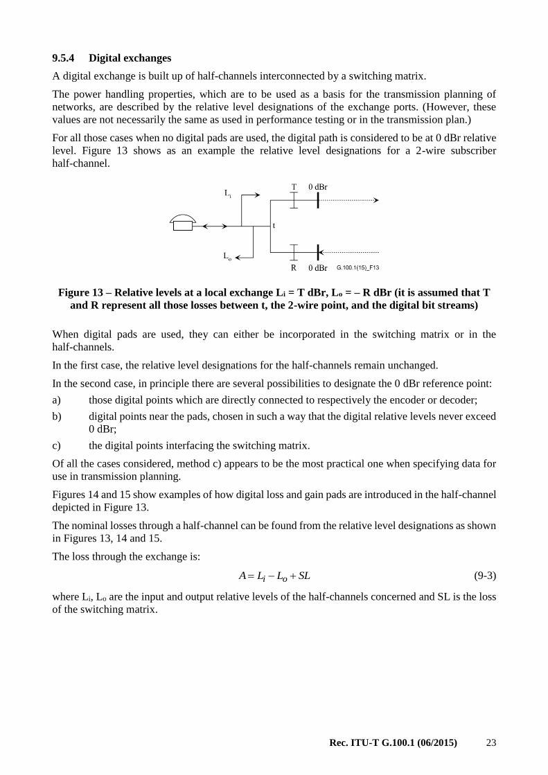
For all those cases when no digital pads are used, the digital path is considered to be at 0 dBr relative
level. Figure 13 shows as an example the relative level designations for a 2-wire subscriber
half-channel.
Figure 13 – Relative levels at a local exchange Li = T dBr, Lo = – R dBr (it is assumed that T
and R represent all those losses between t, the 2-wire point, and the digital bit streams)
When digital pads are used, they can either be incorporated in the switching matrix or in the
half-channels.
In the first case, the relative level designations for the half-channels remain unchanged.
In the second case, in principle there are several possibilities to designate the 0 dBr reference point:
a) those digital points which are directly connected to respectively the encoder or decoder;
b) digital points near the pads, chosen in such a way that the digital relative levels never exceed
0 dBr;
c) the digital points interfacing the switching matrix.
Of all the cases considered, method c) appears to be the most practical one when specifying data for
use in transmission planning.
Figures 14 and 15 show examples of how digital loss and gain pads are introduced in the half-channel
depicted in Figure 13.
The nominal losses through a half-channel can be found from the relative level designations as shown
in Figures 13, 14 and 15.
The loss through the exchange is:
SLLLA oi (9-3)
where Li, Lo are the input and output relative levels of the half-channels concerned and SL is the loss
of the switching matrix.

24 Rec. ITU-T G.100.1 (06/2015)
Figure 14 – Relative levels at a local exchange. Digital loss in the half-channel
Figure 15 – Relative levels at a local exchange. Digital gain in the half-channel
9.6 Relative levels in transmission planning and maintenance
In transmission planning procedures the overall transmission path is divided into sections in ITU-T
vocabulary termed "circuits", each having its own 0 dBr transmission reference point (TRP). Most
often circuits connect switching centres. Sometimes the subscriber line connected to a local exchange
is also termed "circuit". Thus, a circuit is constituted by all permanently interconnected equipment.
In this way maintenance personnel have clearly defined segments with fixed transmission parameters
to supervise.
The physical limits of a circuit are sometimes expressed as being situated at "the middle of the
exchanges". In this case the exchange terminating equipment is included in the circuit ending in the
exchange test point. This practice is common in the public networks and dates back to the times when
most exchanges were analogue.
However, the transmission planner has other options to subdivide the connection into circuits,
provided he clearly defines the interface. Thus, if the digital switching matrix is designed to introduce
loss, the two half-channels 0 dBr points may be considered as ending of circuits with the switching
matrix as a mini-circuit in between.
Exceptionally, the "transmission interface" between the two different maintenance organizations does
not lie at an exchange. This may be the case when a public and a private network are interconnected.
To divide the responsibilities clearly, the public and private links may be designated as belonging to
two different circuits.
One main problem in transmission planning is to obtain a reasonable matching between expected
signal levels and the power handling capabilities of the equipment used in each circuit. Sometimes
also the relative levels at circuit interconnection points cannot be matched to each other so that "level
jumps" have to be introduced.
The circuits are interconnected in the exchanges. In the analogue telephone network, where the
circuits have to have loss to maintain the stability, this often means that the output of one circuit

Rec. ITU-T G.100.1 (06/2015) 25
having a level of A dBr is connected to the input of another circuit having a different level B dBr.
This level difference is often called a "level jump". The "level jump" is the difference in level, i.e.,
B – A dB. The switching points have no loss, the "level jump" only shows that one goes from one set
of dBrs particular to one circuit, to another set of dBrs particular for the other circuit. The loss will
always be present within the circuits themselves.
However, at a speech level of –11 dBm, at a 0 dBr point, pauses excluded, expected as an average for
a large number of subscribers, field measurements of actual speech levels in TRPs show a very large
spread. For this reason, some conventions based on general experience are resorted to instead.
For normal telephony terminals and subscriber lines, the interconnection to the local exchange can be
taken as an "anchor point" to establish a 0 dBr point (see Figure 13). The speech levels are influenced
by the telephony terminal sensitivities. Nevertheless, from Annex C of
[ITU-T G.121] it can be seen that many Administrations found the optimum values to be Li = 0 dBr,
Lo = –6 dBr or –7 dBr.
Regarding how the equipment is incorporated in the network, in most cases it will be possible to
obtain an exact correspondence between the "equipment" and the "circuit" relative levels. Exceptions
sometimes have to be allowed, for instance when for stability reasons extra loss is included in a 4-wire
loop. Another reason might be a lack of suitable level controls in certain equipment (some echo
canceller designs may also need an extra margin against clipping).
An example of additional loss in an analogue 4-wire loop is shown in Figure 16 where an analogue
circuit section is interposed between digital circuit sections. To ensure that the risk of instability and
"hollowness" of a connection will be insignificant, the ITU-T recommends that a 0.5 dB loss is
inserted in analogue or mixed digital/analogue circuits. Thus, in the transmission plan for this circuit,
part of the digital bit stream will be associated with −0.5 dBr.
Figure 16 – Example of (circuit) relative levels
when an analogue link is interposed in a digital chain
Two adjacent circuits each have their own TRPs to which their respective relative levels are referred.
Ideally, at the interface between the circuits, the two relative levels should be the same.
Occasionally, the send relative level is set 0.5 dB lower than the receive level in order to guarantee
stability, namely when analogue 4-wire transmission is used. For instance, two local exchanges are
interconnected via a primary or transit centre with 4-wire analogue switching and transmission. The
net loss in the transit path should be 0.5 dB for stability reasons. The relative levels at the local
exchanges are determined by the properties of the telephony terminals as mentioned before.
Therefore, the 0.5 dB net transmission loss corresponds to a "level-jump" of 0.5 dB at the transit
exchange. A similar example of an international transit connection is given in Figure 17.

26 Rec. ITU-T G.100.1 (06/2015)
Figure 17 – Example showing a (simplified) representation of a transit connection
in an international exchange
Occasionally, the transmission planner may find it convenient to assign a "level-jump" at an interface
between a public and a private circuit, which is not associated with switching (such a level-jump
minimizes the dynamic range and should be as small as possible).
Note that, in general, the total loss of a connection made up of several circuits should be determined
by adding the losses of the individual circuits and not by taking differences in relative levels between
the input and the output of the connection ports (the latter method is only valid when all the consistent
circuits are digital and are not using digital signal processing).
With regard to digital parameters in a complete connection, the transmission planner should also
consider the sum of qdus, the total amount of digital loss or gain introduced and the sum of all level-
jumps.

Rec. ITU-T G.100.1 (06/2015) 27
Appendix I
The neper
(This appendix does not form an integral part of this Recommendation.)
I.1 Introduction
The usage of the neper in telecommunications is no longer recommended by the ITU-T. However,
for reasons of traceability and for the sake of completeness this appendix provides the necessary
information.
I.2 Definition of the neper
The "neper" (symbol Np) expresses the ratio of two field quantities such as voltage or current, the
square of which is proportional to power by the natural logarithm of this ratio. The value of a power
ratio in nepers is one half of the natural logarithm of the power ratio. The values in nepers of the ratio
of two field quantities and of the corresponding powers are equal only if the impedances are equal.
One neper corresponds to the value of e of a field quantity ratio and to the value e2 of a power quantity
ratio.
Sub-multiples such as the decineper (dNp) are also used.
In some disciplines, nepers may be used to express the logarithm of a power ratio without the factor ½.
An example is optical depth or attenuation in radiometry. Such usage is deprecated in
telecommunications in order to avoid ambiguity. Under this definition, the neper would in fact be
equal to 4.34 dB, instead of 8.68 dB as is traditionally the case.
I.3 Use of the decibel and of the neper
As mentioned above, the ITU-T has discontinued to recommend the use of the neper in
telecommunications.
However, for theoretical or scientific calculations, where ratios are expressed in terms of naperian
logarithms, the neper will always be used, implicitly or explicitly.
As a result of some calculations on complex quantities, a real part in nepers and an imaginary part in
radians are obtained. Factors may be applied for converting to decibels or degrees.
The conversion values between the neper and the decibel are as follows:
1 Np = (20 log e) dB 8.686 dB
1 dB = (0.05 ln 10) Np 0.1151 Np

28 Rec. ITU-T G.100.1 (06/2015)
Bibliography
[b-ITU-T B.12] Recommendation ITU-T B.12 (1998), Use of the decibel and the neper in
telecommunications.
[b-ITU-T G.101] Recommendation ITU-T G.101 (2003), The transmission plan.
[b-ITU-T P.10/G.100] Recommendation ITU-T P.10/G.100 (2006), Vocabulary for performance
and quality of service.
[b-ITU-T Q.551] Recommendation ITU-T Q.551 (2002), Transmission characteristics of
digital exchanges.


Printed in Switzerland Geneva, 2015
SERIES OF ITU-T RECOMMENDATIONS
Series A Organization of the work of ITU-T
Series D General tariff principles
Series E Overall network operation, telephone service, service operation and human factors
Series F Non-telephone telecommunication services
Series G Transmission systems and media, digital systems and networks
Series H Audiovisual and multimedia systems
Series I Integrated services digital network
Series J Cable networks and transmission of television, sound programme and other multimedia
signals
Series K Protection against interference
Series L Environment and ICTs, climate change, e-waste, energy efficiency; construction, installation
and protection of cables and other elements of outside plant
Series M Telecommunication management, including TMN and network maintenance
Series N Maintenance: international sound programme and television transmission circuits
Series O Specifications of measuring equipment
Series P Terminals and subjective and objective assessment methods
Series Q Switching and signalling
Series R Telegraph transmission
Series S Telegraph services terminal equipment
Series T Terminals for telematic services
Series U Telegraph switching
Series V Data communication over the telephone network
Series X Data networks, open system communications and security
Series Y Global information infrastructure, Internet protocol aspects and next-generation networks
Series Z Languages and general software aspects for telecommunication systems