Embed Size (px)
Citation preview

Technical Manual No. IOT1000P Effective 8/31/2018
REV LEVEL B
ITT Engineered Valves, LLC
33 CENTERVILLE ROAD LANCASTER, PA 17603-2064
TEL: (717) 509-2200 FAX: (717) 509-2336
www.engvalves.com
INSTALLATION, OPERATION AND MAINTENANCE INSTRUCTIONS
MODEL T1005, T1006, T1007 & T1008
SKOTCH TRIFECTA OIL VALVE SYSTEMS
WARNING
Valves and valve actuators supplied by ITT Engineered Valves, LLC are designed and manufactured using good workmanship and materials, and they meet the applicable industry standards. These valves are available with components of various materials, and they should be used only in services recommended herein or by a company valve engineer. Misapplication of the product may result in injuries or property damage. A selection of valve components of the proper material consistent with the particular performance requirement, is important for proper application.
Examples of the misapplication or misuse of a valve or valve actuator includes use in an application that exceeds the pressure/temperature rating, or failure to maintain the equipment as recommended.

Technical Manual No. IOT1000P Effective 8/31/2018
REV LEVEL B
Record of Revisions
Revision Description Date
- First Issue 09/10/99
A Added reference information for T1007 (Fail in Last Position Fire, Fail Closed Purge)
03/23/04
B Revised Model T1007 to Fail-Closed Non-FM, Model T1008 as FLFC and manual.
08/31/18

Technical Manual No. IOT1000P Effective 8/31/2018
REV LEVEL B
TABLE OF CONTENTS
SECTION PAGE
I. Description .................................................................................... 4
II. Operation ....................................................................................... 5
III. Installation ..................................................................................... 7
IV. Maintenance & Disassembly Instructions ..................................... 10
V. Leak Testing .................................................................................. 18
VI. Proof of Closure Switch Testing ................................................... 19
VII. Miscellaneous Instructions for Special Options ............................ 22
VIII. Spare Parts Ordering Information ................................................. 22
IX. Reference Information ................................................................... 22
DRAWINGS
03-001 Valve Assembly - Model T1000 Systems
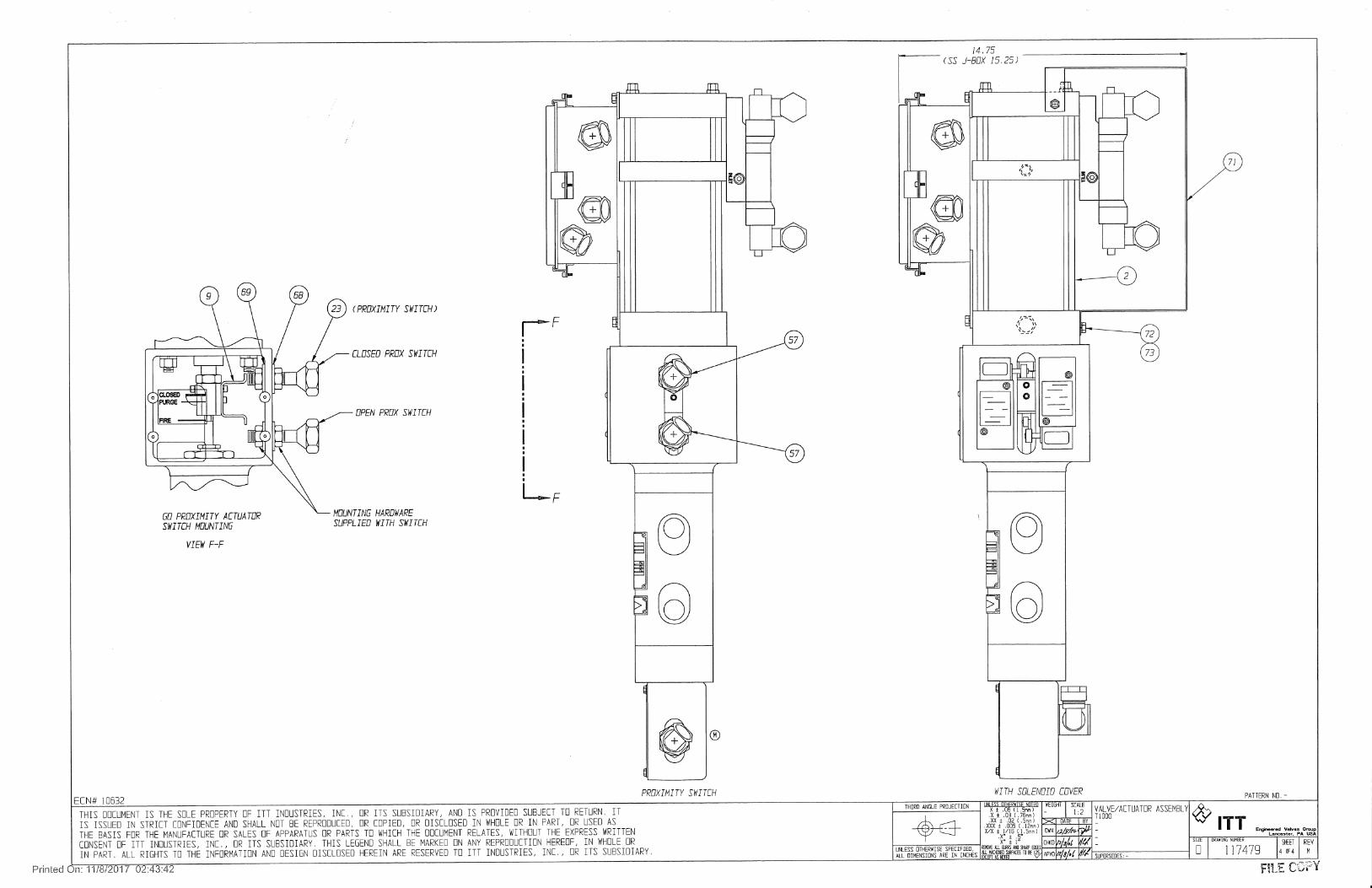
117479 Valve and Actuator Assembly - Model T1000 Systems
117485 Pneumatic Schematic - Fail in Last Position
117486 Pneumatic Schematic - Fail Closed
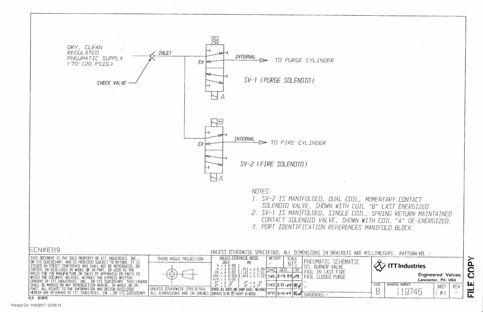
119746 Pneumatic Schematic Oil Valve Fail in Last Fire Fail Closed Purge
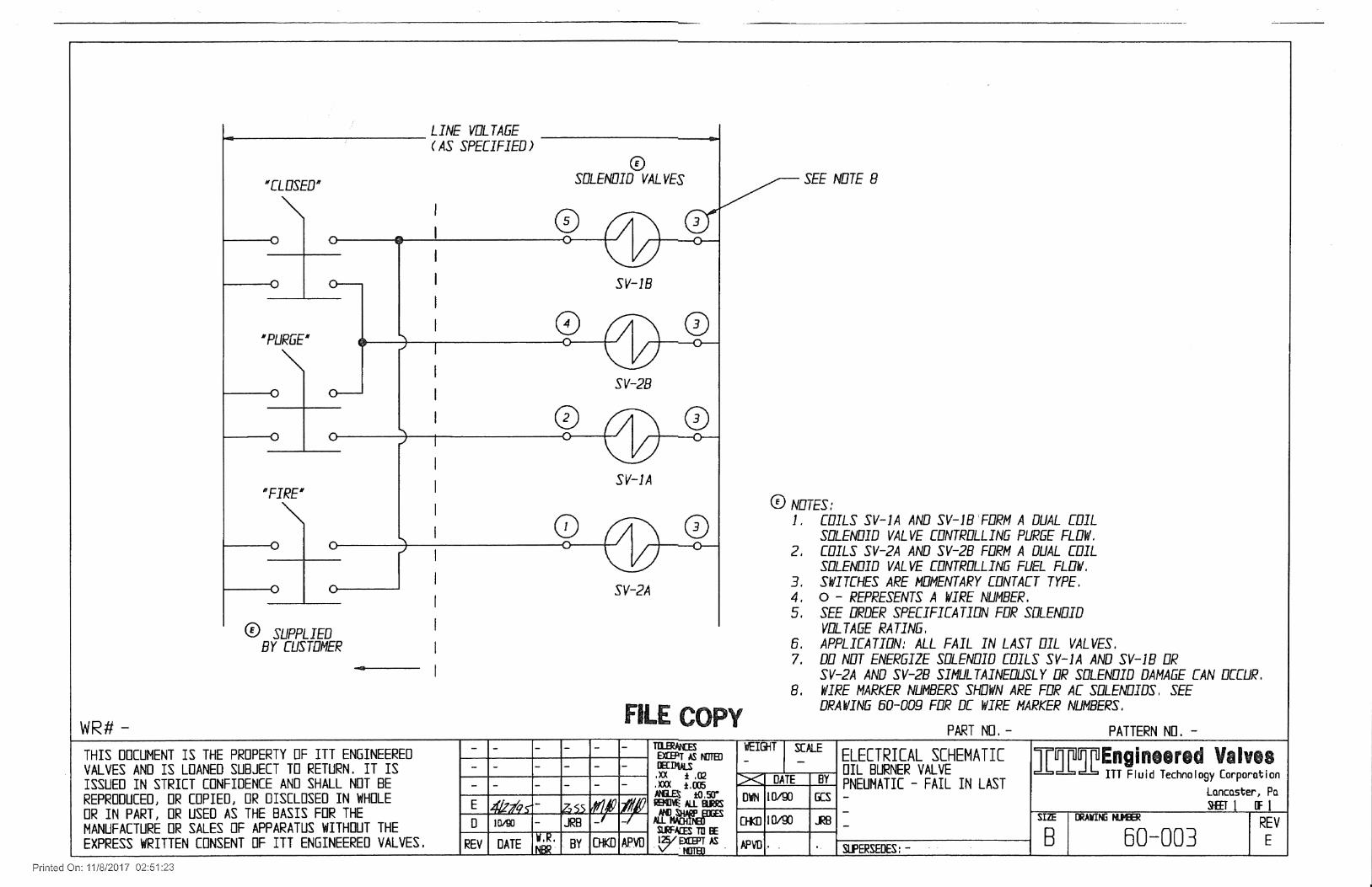
60-003 Electrical Schematic - Fail in Last Position
60-004 Electrical Schematic - Fail in Closed Position
119747 Electric Schematic Oil Valve Fail in Last Fire, Fail Closed Purge
60-008 Wiring Diagram - AC Solenoids
60-009 Wiring Diagram - DC Solenoids
116762 Wiring Diagram - GO Switches

ITT Engineered Valves, LLC Page 4 of 22
Technical Manual No. IOT1000P Effective 8/31/2018
REV LEVEL B
I. DESCRIPTION
The Model T1005, T1006, T1007 and T1008 Oil Valves are an integral valve system with all components housed within a single valve body. It is typically used on all oil-fired burners and igniters where steam or air atomization is required. The Skotch Trifecta's unique two-stem three-seat design enables it to perform all key functions, including fuel sequencing, atomization and purging of downstream piping by providing three distinct valve positions.
1. Closed - Both oil and atomizing/purge media off 2. Fire - Both atomizing and oil flowing while purge is off 3. Purge - Both atomizing and purge media flowing while oil flow is off
The Model T1005 valve system, which is the Fail-in-Last Position model, utilizes a pair of dual coil momentary contact pilot solenoids for pneumatic operation and requires compressed air and electric power to open and close. The system fails in the last position on loss of pneumatic or electric power. It will not hold this position indefinitely if air is lost. The Model T1008 valve system is similar to the T1005 above with the Fire mode being Fail-in-Last Position, however, the Purge mode is Fail Closed. Due to the Fire failure mode, Model T1005, and T1008 valve systems can never be Factory Mutual (FM) approved. The Model T1006 and T1007 valve systems, which are the Fail Closed model, utilizes a pair of single coil maintain contact spring return pilot solenoids for pneumatic operation and requires compressed air and electric power to open. The system closes on a loss of pneumatic or electric power. Model T1006 valves incorporating specific options may be Factory Mutual approved for Fuel Oil Safety Shutoff Valves per FM Approval Standard Class 7400. Valves meeting the requirements of FM are tagged as such. Model T1007 valves are not Factory Mutual listed with valve configuration. A single Skotch oil valve is typically installed in place of a multiple valve arrangement. Consult order specification for detailed specifications of equipment supplied on each project.

ITT Engineered Valves, LLC Page 5 of 22
Technical Manual No. IOT1000P Effective 8/31/2018
REV LEVEL B
II. OPERATION
Refer to Purchase Order Specification or solenoid valve assembly nameplate to determine proper line voltage. Operation is in accordance with reference drawings. Check specific order options and wiring diagrams (60-008 for AC voltage or 60-009 for DC voltage) for electrical terminals supplied inside the junction box.
A. Closed: Oil Flow Off, Purge and Atomizing Media Flow Off
In this position the atomizing valve plug is held against the atomizing seat by the actuator return spring, blocking flow of the atomizing media. The oil valve plug is held in the oil seat by the oil valve return spring, blocking oil flow. The oil valve proof of closure (POC) switch is made. The valve closed limit switch is actuated and the valve open limit switch is deactuated. Model T1005: Energizing both the fire and purge exhaust solenoids coils moves
the system to the closed position. Model T1006 & T1007: De-energizing both the fire and purge solenoids
moves the system to the closed position. Model T1008: Energizing the fire exhaust solenoid coil, and de-energizing the
purge solenoid moves the system to the closed position.
B. Fire: Atomizing Media and Oil Flowing, Purge Off
Pressurizing the Actuator’s Fire cylinder causes the atomizing stem to move downward towards the oil stem. As the atomizing stem contacts the oil stem, it forces the oil plug out of its seat ring initiating oil flow while simultaneously seating in the purge seat. Prior to any oil flowing, the oil valve POC switch changes contact states. The valve open and close limit switches change states from the valve closed position (Valve open actuated & valve closed deactuated). Model T1005, T1008: Energizing the fire solenoid coil moves the system to the
Fire position. Model T1006, T1007: Energizing the fire solenoid causes the valve to go to the
Fire position.

ITT Engineered Valves, LLC Page 6 of 22
Technical Manual No. IOT1000P Effective 8/31/2018
REV LEVEL B
Operational Note: While in the Fire position there is an operational advantage in leaving the Purge solenoid energized while in Fire. In this scenario both actuator cylinders will be pressurized. Doing so will prevent the valve from traveling back to the Closed position causing a momentary loss in Purge pressure. This will help in ensuring the burner flame stays lit as the oil valve closes and the slug of oil remaining in the down stream piping of the valve is evacuated by the purge media. Maintaining a constant pressure on this slug of oil will ensure it is burned completely. If the Purge cylinders were not energized with the Fire cylinders the atomizing valve would close and then open back up for Purge. This will cause a momentary drop in atomizing pressure causing the flame to suck back or possibly extinguish before the remaining slug of oil is evacuated.
C. Purge: Atomizing and Purge Media Flowing, Oil Off
Energizing only the purge solenoid moves the atomizing stem to the purge position. In this position the atomizing plug is positioned between, but not in contact with the atomizing and purge seats. Accordingly, the atomizing stem is not in contact with the oil plug, therefore the oil valve remains in the closed position. The atomizing media flows from the atomizing inlet to both, the atomizing and oil outlets, purging or clearing any oil which, remains in the downstream oil piping. There is no oil flow in the purge position and the oil valve POC switch is made. Both the valve open and valve closed limit switches are deactuated.
D. Notes
Some installations may require tip warm up prior to light-off. This can be accomplished by commanding the valve to "Purge" for a period of time before commanding to "Fire". Atomizing steam then passes down both atomizing and fuel lines, warming up the tip in preparation for ignition. Due to the stacked tandem cylinder design of the actuator, when both "Fire" and "Purge" solenoids are energized, the "Fire" command will override and the assembly will shift to the full open or "Fire" position. The Fire Solenoid must be de-energized for the valve to move to the purge position.

ITT Engineered Valves, LLC Page 7 of 22
Technical Manual No. IOT1000P Effective 8/31/2018
REV LEVEL B
Assemblies may include a speed control (black in color) which is located between the Fire solenoid body (red anodize) and the manifold adapter (gold anodize). This is used to slow opening time of the assembly when moving to the "Fire" position. It has no impact on closing time. Factory setting prior to shipment is full open. Speed adjustments are made using a small flat blade screwdriver. The adjustment screw is located on the top end surface of the plate.
Model T1005: Solenoid operated pilot valves are momentary contact type. As such, upon loss of pneumatic supply pressure or electrical power, the system will hold last position for some period of time.
Model T1006 & T1007: Solenoid operated pilot valves are maintained contact spring return type. As such, upon loss of pneumatic supply pressure or electrical power, the system will fail in the closed position.
Model T1008: Fire solenoid operated pilot valves are momentary contact type. As such, upon loss of pneumatic supply pressure or electrical power, the system will hold last position for some period of time. Purge solenoid operated pilot valves are maintained contact spring return type. As such, upon loss of pneumatic supply pressure or electrical power, the system will fail in the closed position.
III. INSTALLATION
WARNING
Prior to installation and/or start-up, inlet piping should be verified as being free of dirt, grit, welding slag, or other particulate contamination.
Failure to do so may result in damage to valve internals.
A. Unpacking
Do not remove protective plugs from valve and solenoid until ready to install. If plastic protective caps are missing, verify no debris or foreign objects are inside valve.
Transporting - Use proper hoisting procedures to avoid damage to valve. Do not lift by conduit, switches, etc.
Purge all air lines prior to connecting solenoids.

ITT Engineered Valves, LLC Page 8 of 22
Technical Manual No. IOT1000P Effective 8/31/2018
REV LEVEL B
B. Valve Installation
The oil valve installation should be in accordance with standard practices for end connection selected. Valves with weld end connections are supplied with end connections of sufficient length to prevent thermal damage to valve internals. As a safety precaution, methods to thermally block the transfer of heat to the valve body should be employed during welding. The end connections should not be modified to a shorter length. The weight of the valve must be properly supported to prevent excessive piping stresses. The valve may be installed in any position, but the actuator should be supported when the valve is installed horizontally. Adequate clearance should be provided for valve maintenance and repair.
CAUTION
Valve must be installed in proper flow direction, per valve flow tag. Improper installation will result in fuel
contamination of atomizing piping, and improper valve operation.
CAUTION
Ensure piping upstream of fuel inlet DOES NOT include a check valve since this will cause hydraulic locking of the oil
valve in the closed position.

ITT Engineered Valves, LLC Page 9 of 22
Technical Manual No. IOT1000P Effective 8/31/2018
REV LEVEL B
C. Pneumatic/Electrical Hook Up
Electrical power and clean dry air are required to operate the T1000 oil valve system. Wiring should be in accordance with referenced drawings and all applicable codes. All wiring connections are on the main terminal board located inside the Junction Box. Supply air is to be connected to Solenoid Assembly manifold block (See Drawings 117485 & 117486). Pneumatic supply air should be clean, dry and between 70 to 120 PSIG (482.3 - 826.8 KPa) at all times. It is important for proper valve performance that this pressure is available at the valve at all times. Historically, many field problems can be associated with inadequate pneumatic supply requirements or contamination.
Warning
Make certain electrical supply is isolated and tagged out before proceeding with electrical connections.
Note: Some assemblies may include a preset filter regulator installed in supply piping.
Use suitable thread sealing compound for pneumatic connection. Do not use PTFE tape.
The exhaust side of the solenoid should not be restricted, as this will slow down the closing rate of the valve.
ITT Engineered Valves, LLC Page 10 of 22
Technical Manual No. IOT1000P Effective 8/31/2018
REV LEVEL B
D. Start-Up
When valve is placed in service, stroke the main stem and oil stem two or three times (Fire cycles) and then check for packing leaks. If leakage is present, tighten adjusting nut 1/8 turn, stroke valve several times to ensure proper setting of packing and recheck. Repeat until leakage is stopped. This should occur before nut is completely tight. If leakage is present when nut is completely tight, packing must be replaced and the stem inspected for wear. Refer to instructions in Section V.
CAUTION
DO NOT OVER-TIGHTEN PACKING. Over-tightened packing may cause excessive stem friction, inhibiting stem
movement.
IV. MAINTENANCE AND DISASSEMBLY INSTRUCTIONS
A. Maintenance
The Skotch Trifecta Valve Systems requires periodic maintenance and adjustments in order to function properly. The following is a list of items which, must be inspected on a regular basis.
1. Testing Oil Valve Seal
Periodic leak testing should be performed per all applicable codes to verify proper operation of oil valve seal. See Section V for leak testing procedures.
2. POC Verification
Periodic testing should be performed per all applicable codes to verify proper operation of the oil valve POC switch. See Section VI for POC switch setting procedures.

ITT Engineered Valves, LLC Page 11 of 22
Technical Manual No. IOT1000P Effective 8/31/2018
REV LEVEL B
3. Packing Inspection
Both the oil valve and the atomizing packing should be inspected regularly for leakage. If any leakage is noted the packing should be adjusted until the leakage has stopped. See Section III.D for instructions.
4. Pneumatic System Leaks
The pneumatic system (fittings, solenoid, actuator, etc.) should be inspected regularly for leakage or other damage. Any leakage or damage must be repaired or replaced immediately.
5. Body to End Flange Joint Inspection
Body end flange joints should be inspected regularly for leakage. Any leakage should be repaired immediately. See following Section for instructions.
CAUTION
Failure to repair atomizing end flange joint on steam atomized systems may result in steam cutting of valve body, end flange assembly or both. This may result in
serious damage to the valve.
B. Disassembly
All T1000 series Skotch Trifecta Valve Systems may be disassembled without removal from piping. It is recommended the work area be as clean as possible. Ensure all manual isolation valves are closed and tagged out, all electrical circuits are de-energized and isolate the pneumatic supply. BE SAFE!

ITT Engineered Valves, LLC Page 12 of 22
Technical Manual No. IOT1000P Effective 8/31/2018
REV LEVEL B
The following instructions describe how to fully disassemble the valve system. Individual corrective tasks may not require complete disassembly. The user should judge what steps are appropriate for each task.
Special tools are needed to remove the valve seats. The following tools are available:
ITT P/N: 44425, T1000/T2000 seat ring tool. This tool will remove all three seats (atomizing, purge and oil) from the oil valve body and is needed when servicing the atomizing side of the valve.
NOTE: Customers that do not feel comfortable with rebuilding and testing Skotch valves can have them rebuilt by the factory. Call the number located on the front cover or (800) 366-1111 and ask to speak to Skotch, Customer Service for quotation and instructions.
1. Actuator Removal
Note: Pneumatic supply pressure is required for actuator removal.
CAUTION
Valve system MUST be stroked to purge position prior to decoupling stem connector for actuator
removal. Failure to do so may result in damage to upper seat ring and/or main stem subassembly.
Commence actuator removal by removing the Junction Box and Solenoid Manifold Adapter Block from the actuator. Allow components to hang by the conduit. Remove the screws securing the Yoke Lens to the Yoke. Loosen Set Screw in the Stem Connector. Loosen Stem Connector Jam Nut. Stroke system to "Purge" in accordance with operating instructions (Paragraph II.C). Unscrew Stem Connector from Actuator Output Shaft. After 6-7 turns, stroke system to "Closed" (Paragraph II.A) and continue to unscrew Stem Connector. Remove the four hex nuts holding the Actuator to the Yoke. Lift Actuator off of valve, being careful not to hit Valve Stem. The Yoke Box can be removed by removing the Yoke Lock Nut from the valve End Flange.
2. Atomizing/Purge Valve Disassembly

ITT Engineered Valves, LLC Page 13 of 22
Technical Manual No. IOT1000P Effective 8/31/2018
REV LEVEL B
After completing Paragraph IV.B.1, unscrew Socket Head Cap Screws (Item 6) which retain End Flange (Item 2) to Body (Item 1). Remove End Flange and Body Gasket (Item 7). Be sure to thoroughly clean mating gasket surface, but do not damage it. Insert Seat Ring Wrench (P/N: 44425) into lugs on Upper Seat Ring (Item 9). Unscrew and remove Seat Ring (Item 9), Seat Ring Gasket (Item 21), and Main Stem (Item 8). Insert other end of wrench into holes in Purge Seat Ring (Item 10) and remove.
3. Oil Valve Disassembly
Remove Hex Nuts (Item 29) holding Limit Switch Box (Item 13) to End Flange (Item 39). Note: These two nuts must be removed uniformly. Remove Limit Switch Box (Item 13) and Oil Valve Return Spring (Item 19). Loosen Set Screw (Item 18) and unscrew Spring Seat (Item 17) from Oil Stem (Item 12). Remove the Socket Head Cap Screws (Item 6) securing End Flange (Item 39) to Body (Item 1), then remove End Flange (Item 39), Oil Stem (Item 12) and Body Gasket (Item 7). Insert Seat Ring Wrench in lugs of Oil Seat Ring (Item 11), and remove Oil Seat Ring and Seat Ring Gasket (Item 21).
CAUTION
To properly unload the Oil Valve Return Spring, make certain the nuts (Item 29) unthread from the studs. A hex
wrench can be used to keep the studs from rotating.

ITT Engineered Valves, LLC Page 14 of 22
Technical Manual No. IOT1000P Effective 8/31/2018
REV LEVEL B
4. Packing Removal
After removing end flanges in Paragraphs IV.B.2 and IV.B.3 above, unscrew Packing Nut (Item 3) and remove Packing (Item 4) and Packing Spring (Item 5).
5. Actuator Disassembly
The actuator should not be disassembled or repaired. Consult factory.
6. Inspection
After disassembly, inspect all sealing and bearing surfaces on valve and actuator parts for physical damage including nicks, scratches or corrosion. Be sure all gasket surfaces are thoroughly cleaned and free of old gasket material. Replace any damaged soft goods such as piston seals, o-rings and rod wipers. Replace packing. Inspect atomizing, oil and purge seat ring and the oil and atomizing stem/plugs. If any visual damage is apparent, replace part.
C. Reassembly
1. Actuator Assembly to Yoke
Mount yoke to cylinder assembly with four hex nuts and lock washers. Replace switches, solenoid manifold, and junction box. Remake switch and solenoid wiring to terminal blocks per wiring diagram.

ITT Engineered Valves, LLC Page 15 of 22
Technical Manual No. IOT1000P Effective 8/31/2018
REV LEVEL B
2. Packing/End Flange Reassembly
Place Packing Spring (Item 5) in stuffing box. Lubricate each individual packing component (Item 4) with KRYTOX lubricant from DuPont. Individually install the components into the End Flange. The assembly order is male ring first, then chevrons, then female ring. Screw packing nut (Item 3) into end flange (Item 2 or 39) and snug up by hand. Do not tighten at this time. Take special precaution not to damage the packing when sliding over the stem threads. Some means of protecting the packing from damage during installation should be employed.
WARNING
Assure packing is installed in the correct orientation. See Drawing 03-001 for proper orientation. Failure to do so will cause the valve to leak severely from packing gland.
3. Oil Valve Reassembly
Lubricate the Oil Seat Ring (Item 11) soft seal sealing surface located on the inside diameter with Magnalube-G from the Carleton-Stuart Corporation. Clean the body oil seat threads and gasket area. Apply Grafoil GTS sealant to both the Body (Item 1) and Oil Valve Seat Ring threads (Item 11), place the Seat Ring Gasket (Item 21) on the Oil Valve Seat Ring (Item 11) and thread into Body (Item 1). Torque to 130 Ft-Lbs (176.3 Nm). Lubricate the oil stem plug with Magnalube-G and the shaft with antiseize lubricant. Carefully slide the oil stem (Item 12) into the End Flange (Item 39), making sure not to damage the Packing (Item 4). Slide the Body Gasket (Item 7) over the End Flange subassembly (Item 39). Lubricate the 4 end flange Screws (Item 6) with antiseize compound and fasten the End Flange assembly (Item 39) onto the Valve Body (Item 1), ensuring the limit switch box Studs (Item 14) are properly oriented (In line with piping). Torque the end flange Screws (Item 6) in two uniform increments. Torque screws initially in a crisscross pattern to 40 Ft-Lbs (54.2 Nm), repeat using 65-70 Ft-Lbs (88.1 - 94.9 Nm) and recheck. Push the Oil Stem (Item 12) up into the Valve Body (Item 1) until it seats in the Oil Valve Seat Ring (Item 11). This may require that the Oil Stem (Item 12) be lightly struck with a mallet until it is fully seated. Screw Spring Seat (Item 17) onto the Valve Stem (Item 12). Hold the Limit Switch Box (Item 13) in place, while adjusting the spring seat position to 2.05" (52.1 mm). This is measured from the inside surface of the Switch Box (Item 13) on which the spring rest to the spring seating surface on the Spring

ITT Engineered Valves, LLC Page 16 of 22
Technical Manual No. IOT1000P Effective 8/31/2018
REV LEVEL B
Seat (Item 17). Tighten the Set Screw (Item 18) so the spring seat is secure. Remove the Limit Switch Box (Item 13). Place Oil Valve Return Spring (Item 19) into the Spring Seat (Item 17) and mount the Limit Switch Box (Item 13) using the 2 mounting Nuts (Item 29) with Lock Washers (Item 28). Tighten these fasteners in a uniform manner, so the box is not cocked during assembly. Item 29 should be torqued to approximately 125 In-Lbs (14.1 Nm). Mount the Oil Valve POC Switch (Item 20) to the Limit Switch Box (Item 13) using Washer (Item 23), Lock Washer (Item 24) and Screw (Item 22). Verify the Spring Seat (Item 17) dimension is set correctly. The Oil Valve POC Switch must be set per section VI.
4. Atomizing/Purge Valve Reassembly
Clean the thread/surface area in the Body (Item 1) of both the Purge Seat (Item 10) and Seat Ring (Item 9). Apply Grafoil GTS sealant to both the Purge Seat (Item 10) and Body (Item 1) threads, and screw into the Valve Body (Item 1). Torque to 100 Ft-Lbs (135.6 Nm). Insert the Main Stem (Item 8) into the Valve Body (Item 1). Place the Seat Ring Gasket (Item 21) over the Seat Ring (Item 9), apply Grafoil GTS sealant to both the Seat Ring (Item 9) threads and body threads and screw into Valve Body (Item 1). Torque to 130 Ft-Lbs (176.3 Nm). Place Body Gasket (Item 7) on End Flange (Item 2). Carefully slide End Flange (Item 2) and Body Gasket (Item 7) over the Main Stem (Item 8) making sure not to damage the Packing (Item 4). Lubricate the 4 end flange Screws (Item 6) with antiseize compound and fasten the End Flange assembly (Item 2) onto the Valve Body (Item 1). Torque the end flange Screws (Item 6) in two uniform increments. Torque screws initially in a crisscross pattern to 40 Ft-Lbs (54.2 Nm), repeat using 65-70 Ft-Lbs (88.1 - 94.9 Nm) and recheck. Screw the stem connector onto the Main Stem (Item 8) and tighten set screws.

ITT Engineered Valves, LLC Page 17 of 22
Technical Manual No. IOT1000P Effective 8/31/2018
REV LEVEL B
5. Actuator Reinstallation
Carefully place actuator onto valve. Screw yoke lock nut onto valve end flange (Item 2) hand tight. Slide valve stem up and thread stem connector onto actuator shaft. Rotate slowly until resistance is felt. Securely tighten yoke lock nut. Make pneumatic and electrical connections to assembly and stroke valve to "Purge" (Paragraph II.C). Rotate connector onto shaft one additional turn plus enough to line up switch trip bracket mounting holes. Tighten the jam nut, and fasten set screw located in the stem connector. Close valve (Paragraph II.A) and install switch trip bracket and indicator onto stem connector. The valve is now ready for testing.
6. Test
Conduct the following tests to assure system performance is satisfactory after rebuild.
a) Valve Stroke
Verify no oil stem movement occurs when the valve strokes from the Closed to Purge position. If the oil stem moves, thread stem connector onto actuator shaft an additional turn while the valve is in Purge and retest. Continue until no movement occurs.
b) Auxiliary Open/Close Switches
Using an electrical testing device verify the Valve Closed limit switch is actuated only when the valve is in the Closed position and the Valve Open limit switch is actuated only when the valve is in the Fire position. Ensure neither switch is actuated when in Purge. Limit switches are adjusted by repositioning the switch roller levers.
c) Oil Valve Proof of Closure
The oil valve Proof of Closure switch must be adjusted in accordance to Section VI.

ITT Engineered Valves, LLC Page 18 of 22
Technical Manual No. IOT1000P Effective 8/31/2018
REV LEVEL B
V. Leak Testing After assembly, the Skotch Trifecta Valve should be leak tested to verify proper operation as follows:
A. Atomizing Seat
1. Place the valve in the Closed position. 2. The fuel inlet and outlet ports must be plugged so that test media cannot
escape for these ports. 3. Pressurize the atomizing inlet to 50 PSIG (344.7 KPa) air while
monitoring the leakage rate from the atomizing outlet. The leakage rate should not exceed ANSI Class IV limits or 1254 cc/min.
4. If leakage is excessive, stroke the valve 10 to 20 times to allow the metal
seat to wear in with the metal plug and retest the valve. If valve leakage is still excessive, the main stem and seat should be replaced and the valve retested.
Note: If the actuator was removed anytime prior to testing, the actuator/valve
coupling nut should be checked for proper installation. The atomizing stem closure force is due to the return spring located inside the actuator. If the coupling nut is not adjusted correctly it is possible for the actuator to reach its home position without the atomizing plug contacting the seat. If this occurs atomizing seat leakage will take place regardless of the plug and seat condition. The atomizing seat and plug should limit the actuator travel in the Closed position.
B. Purge Seat
1. Stroke the valve to the Fire position using a control pressure between 70
and 120 PSIG (482.6 - 827.4 KPa). 2. The atomizing outlet and fuel inlet should be plugged to keep the test
media from escaping from these ports.
ITT Engineered Valves, LLC Page 19 of 22
Technical Manual No. IOT1000P Effective 8/31/2018
REV LEVEL B
3. Pressurize the atomizing inlet to 50 PSIG (344.7 KPa) air while monitoring the fuel outlet port for leakage. The allowable leakage rate per ANSI Class IV is 439 cc/min.
4. If leakage is excessive, stroke the valve 10 to 20 times to allow the metal
seat to wear in with the metal plug and retest the valve. If valve leakage is still excessive, the main stem and purge seat should be replaced and the valve retested.
C. Oil Seat
1. The valve should be in fully closed position. 2. The atomizing inlet and outlet should be plugged. 3. Pressurize the fuel inlet port to 50 PSIG (344.7 KPa) air while measuring
the leakage rate from the fuel outlet. The allowable leakage rate is one bubble per minute or Class VI.
4. If leakage is excessive, stroke the valve 10 to 20 times to allow the soft
seal in the oil seat to wear in with the metal plug and retest the valve. If valve leakage is still excessive the oil seat and/or stem should be replaced and the valve retested.
VI. PROOF OF CLOSURE (POC) SWITCH TESTING The POC switches should be tested after the valve has been leak tested. The intent of the Proof of Closure (POC) switch is to prove the valve is in the closed position. To accomplish this, the oil valve is designed with valve seal over-travel. That is, the seal will stop the flow of oil and continue to move in the valve seat bore until the metal seat is made. During this portion of valve stroke the oil valve is effectively sealed, the POC switch contacts must change state. That is, the POC Switch changes state before oil flows regardless of whether the valve moves from the Closed position to Fire or Fire to Closed (Purge).
A. Limit Switches
1. Ensure the valve is in the closed position.
2. Wire the switch to a test device. 3. Loosen switch and push it towards the end flange (up - orientation
ITT Engineered Valves, LLC Page 20 of 22
Technical Manual No. IOT1000P Effective 8/31/2018
REV LEVEL B
assumes the valve actuator is on top) to edge of slot or until switch boot hits the edge of the hole. This will typically move the switch roller actuator past the tripping device.
4. Move the switch away from the end flange (down) until it trips. Try and
keep the switch level. 5. Mark the limit switch box 0.14" (3.6 mm) from the switch surface
opposite the end flange (bottom surface), for the entire length of the switch. This can be accomplished by placing a 0.14" (3.6 mm) thick metal plate on the switch and marking along the edge. Caution with how close the mark is to the plate. If the marking device is always 0.03" (0.8 mm) higher, the plate should then be 0.11" (2.8 mm), so the end result is always 0.14" (3.6 mm).
6. Move switch to the line and tighten the two screws to prevent movement. 7. Plug the atomizing inlet and outlet pipes. 8. With the oil valve fully closed, pressurize the oil inlet to 10 to 20 PSIG
(68.9 - 137.9 KPa). While monitoring the outlet for leakage, slowly open the valve. The normally open contacts of the switch should change state before flow commences (> 24 in3/Hr or 400 cc/Hr). If it does not, loosen the screws, securing the switch and move the switch downward 0.015" (0.4 mm). Tighten retaining screws and repeat test.
9. Pressurize the oil valve inlet between 10 and 20 PSIG (68.9 - 137.9 KPa)
while monitoring the outlet for leakage. Stroke the valve to open position. Slowly close the valve while monitoring the normally open switch contacts. Flow should cease (< 24 in3/Hr or 400 cc/Hr) before contacts change state. If it does not, loosen the screws, securing the switch and move the switch upward 0.015" (0.4 mm). Tighten retaining screws and repeat test. If any adjustments are made during this step, step 8 must be repeated.
10. Switches are properly set when both conditions in Step 8 and 9 are
satisfied.

ITT Engineered Valves, LLC Page 21 of 22
Technical Manual No. IOT1000P Effective 8/31/2018
REV LEVEL B
B. GO Switches
1. Ensure the valve is in the closed position.
2. Wire the switch to a test device.
3. Loosen switch and push it towards the end flange (up - orientationassumes the valve actuator is on top) to top of slot of POC box. This willtypically move the switch past the target device.
4. Move the switch away from the end flange (down) until it trips. Try andkeep the switch level. Continue to slide the switch for additional 1/32”.Tighten switch to POC box and ensuring the distance between the end ofswitch and target is per manufacturer’s recommendations.
5. Plug the atomizing inlet and outlet pipes.
6. With the oil valve fully closed, pressurize the oil inlet to 10 to 20 PSIG(68.9 - 137.9 KPa). While monitoring the outlet for leakage, slowly openthe valve. The normally open contacts of the switch should change statebefore flow commences (> 24 in3/Hr or 400 cc/Hr). If it does not, loosenthe screws, securing the switch and move the switch downward 0.015"(0.4 mm). Tighten retaining screws and repeat test.
7. Pressurize the oil valve inlet between 10 and 20 PSIG (68.9 - 137.9 KPa)while monitoring the outlet for leakage. Stroke the valve to open position.Slowly close the valve while monitoring the normally open switchcontacts. Flow should cease (< 24 in3/Hr or 400 cc/Hr) before contactschange state. If it does not, loosen the screws, securing the switch andmove the switch upward 0.015" (0.4 mm). Tighten retaining screws andrepeat test. If any adjustments are made during this step, step 6 must berepeated.
8. Switches are properly set when both conditions in Step 6 and 7 aresatisfied.

ITT Engineered Valves, LLC Page 22 of 22
Technical Manual No. IOT1000P Effective 8/31/2018
REV LEVEL B
VII. MISCELLANEOUS INSTRUCTIONS FOR SPECIAL OPTIONS
Due to customer requirements, some T1000 Systems incorporate special options. Anyspecial procedures not covered in the above material can be found in the ReferenceSection of this manual as addenda.
VIII. SPARE PARTS ORDERING INFORMATION
Orders for T1000 Systems Spare Parts should be placed with
ITT Engineered Valves, LLC 33 Centerville Road Lancaster, PA 17603-2064
Phone: 717-509-2200 Fax: 800-348-9000
Please be advised that spare parts should be ordered directly from ITT Engineered Valves, as such materials are specially designed for Skotch Trifecta Valve Systems. Other replacement parts, although they may be similar in function, will void the FM rating. To maintain FM Approval, FM also requires technicians servicing/repairing the Skotch Trifecta Valve Systems to be trained by ITT Engineered Valves.
IX. REFERENCE INFORMATION
The following pages contain drawings and reference information alluded to in abovesections.