Embed Size (px)
Citation preview
17/10/2012 ITSO-C153
Page | 1
Government of India Civil Aviation Department
Directorate General of Civil Aviation Aircraft Engineering Directorate
New Delhi
Indian Technical Standard Order
Subject: INTEGRATED MODULAR AVIONICS HARDWARE ELEMENTS
1. PURPOSE: This Indian Technical Standard Order (ITSO) prescribes the minimum performance standards (MPS) criteria that an Integrated Modular Avionics (IMA) hardware element must meet to be identified with the applicable ITSO markings. 2. APPLICABILITY:
a. This ITSO is effective for new applications submitted after the effective date of this ITSO. The standards of this ITSO apply to the following hardware elements:
(1) Hardware modules, and
(2) Cabinets or racks that host hardware modules.
b. The hardware elements manufactured to comply with this ITSO may be used to support functional TSOs/ITSOs (such as, a Global Positioning System, TSO-C129a) or systems approved under CAR 21 and Code of Federal Regulations (14 CFR) parts 23, 25, 27, 29, 33 or 35 (for example, a braking system approved as part of a type certificate). Functional TSO/ITSO authorizations and aircraft-level approvals are not covered by this ITSO.
c. Appendix 3 provides a summary of the terminology applicable to hardware elements. 3. REQUIREMENTS: Hardware elements identified and manufactured on or after the effective date of this ITSO must meet the MPS for hardware elements. Appendix 1 of this ITSO provides the criteria for developing these MPS.
a. Functionality: This ITSO applies to equipment intended to meet MPS developed to the criteria of Appendix 1. This ITSO does not specify the aircraft functions that the system is intended to perform. It does, however, provide environmental qualification testing requirements for hardware that supports the generic capability to receive, process, and output
ITSO-C153 Effective Date: 17th October 2012
17/10/2012 ITSO-C153
Page | 2
data. Elements that the Directorate General of Civil Aviation (DGCA) authorizes under this ITSO may also meet the functional requirements of other TSOs/ITSOs when loaded with the appropriate software applications. The combination of hardware and software would then be granted additional functional ITSO authorizations by the DGCA for all applicable TSOs/ITSOs. Functions performed by the equipment or systems without ITSO authorization must be evaluated and approved by the DGCA as part of the aircraft installation.
b. Functional Limitations:
(1) Equipment used to generate radio frequency signals for intentional transmitters is not covered by this ITSO.
(2) Software functionality under this ITSO is limited to software that enables electronic
part marking and/or future loading of functional software. c. Failure Condition Classification: The failure condition classification(s) will depend
on the implemented functions and their intended use in a specific aircraft environment. This classification is beyond the scope of this ITSO and must be determined by the safety assessment conducted as part of the installation approval. The manufacturer must state the hardware design assurance and software levels to which each hardware element was developed. Any assumptions about the aircraft installation, interfacing software and hardware, or operation required to maintain the hardware design assurance and software levels should also be stated and included in the installation limitations or instructions.
d. Functional Qualification: The manufacturer must define MPS for each hardware
element. The functional qualification configuration must be specified in the MPS developed as per Appendix1, Section 5.The required performance of each hardware element must comply with the manufacturer’s MPS developed as per the Appendix 1 criteria.
Note: If software that enables software loading and/or electronic part marking capability
is being approved under this ITSO, then that software functionality must be validated by the DGCA during installation approval of the IMA system.
e. Environmental Qualification: The manufacturer must test the equipment as per the conditions specified in section 6 of Appendix 1. This section refers to RTCA/DO-160G, Environment Conditions and Test Procedures for Airborne Equipment, dated December 08, 2010.
f. Software Design Assurance: Hardware elements may include software to enable
software loading and/or electronic part marking. The DGCA will approve only this kind of software under this ITSO. If such software is included, it must be developed in accordance with RTCA/DO-178B, Software Considerations in Airborne Systems and Equipment Certification, dated December 1, 1992 to the software level determined by the hardware element manufacturer.
g. Hardware Design Assurance: If the hardware element contains electronic devices
whose functions cannot be feasibly evaluated by test and/or analysis, the electronic devices must comply with RTCA/DO-254, Design Assurance Guidance for Airborne Electronic Hardware, dated April 19, 2000, to the design assurance level determined by the hardware element manufacturer.
17/10/2012 ITSO-C153
Page | 3
h. Configuration Management: Manufacturers must include design features in each hardware element that support a robust automatic configuration management function. This functionality may not be fully operational until actual installation. The manufacturer must be able to show that, by either mechanical means or automatic electronic monitoring of the integrated assemblies, the higher-level assemblies will only be assembled according to the intended design or that incorrect assembly can be detected at power-up. Furthermore, for individual hardware elements that require interfaces to other system equipment through a mechanical or electrical connector(s), the manufacturer must be able to show that each element, by either mechanical means or automatic electronic monitoring of the higher level assembly, will either prevent an incorrect connection or that an incorrect connection will be detected before any dispatch. The manufacturer must consider failure of the configuration management design features in the safety assessment performed on the installed IMA system in each unique aircraft configuration.
i. Quality Control: To comply with the standards of this ITSO for a hardware element, the manufacturer must be able to provide the quality control data items and meet the requirements of CAR21.143. Additionally, each hardware element manufactured must conform to the approved type design.
j. Deviations: The DGCA has provisions for alternative or equivalent means of compliance to the criteria in this ITSO. Manufacturers invoking these provisions must demonstrate that they maintain an equivalent level of safety and must apply for a deviation as per CAR21.610.
4. MARKING: The marking information specified in CAR 21.609(e)/21.807 shall be legibly and permanently marked on each hardware element manufactured under this ITSO except;
i) In CAR 21.807 (a) 2, use the name, type, and part number.
ii) In CAR 21.807 (a) 3, use both the date of manufacture and serial number of the article.
Additionally;
a. To support maintenance, the hardware element’s part number may also be marked in
multiple places on the element.
b. Each separate hardware element that is manufactured under this ITSO may also support a means by which the required information can be determined using an external means (for example, an electronic display).
c. Each hardware element approved under this ITSO may contain software to enable electronic part marking and/or future loading of functional software.
d. If the hardware element includes software (that is, software to enable loading and/or electronic part marking), separate part numbers may be utilized for hardware and software.
e. Each part number must uniquely identify the configuration (including modification status).

17/10/2012 ITSO-C153
Page | 4
f. Each rack or cabinet approved under this ITSO must be marked with a note “ITSO Authorization for rack only” or “ITSO Authorization for cabinet only”. This note should be on the ITSO nameplate or in close proximity to the nameplate. 5. APPLICATION DATA REQUIREMENTS: Under CAR 21.605, a manufacturer must furnish to the DGCA (AED) one copy of each of the following technical data in support of design and production approval:
a. Operating instructions and equipment limitations, including description of the robust automatic configuration management design features.
b. Installation procedures and limitations. The limitations must ensure that the hardware element, when installed according to the installation procedures, continues to meet the requirements of this ITSO.
(1) The limitations must also identify any unique aspects of the installation and must include the following note: “The conditions and tests required for ITSO authorization of this hardware element are minimum performance standards. Those installing this hardware element either on or within a specific type or class of aircraft are responsible for determining that the installation conditions are within the ITSO standards. This hardware element may be installed only if evaluation by the applicant (i.e., the user/installer) documents an acceptable installation as per Title 14 of the Code of Federal Regulations part 43 or the applicable airworthiness requirements and is approved by the DGCA.”
(2) If software to enable future software loading and/or electronic part marking is included in the hardware element, the software level applied under this ITSO must be commensurate with the installation safety assessment and documented in the installation procedures and limitations.
c. Schematic drawings, applicable to the installation procedures.
d. Wiring diagrams, applicable to the installation procedures.
e. List of the components (by part number) that make up the hardware element complying with this ITSO.
f. Instructions, in the form of a Component Maintenance Manual (CMM). These
instructions contain information on the periodic maintenance, calibration, and repair to support the continued airworthiness of installed hardware elements, including recommended inspection intervals and service life. These instructions for continued airworthiness must be in accordance with CAR 21.61.
g. Material and process specifications list.
h. An environmental qualifications form as described in RTCA/DO-160G for each hardware element.
i. The manufacturer’s data sheet described in section 8 of this ITSO. j. The MPS for each hardware element. (See Appendix 1 for MPS development criteria.)
17/10/2012 ITSO-C153
Page | 5
k. Manufacturer’s ITSO qualification test report. l. Nameplate drawing providing the information required by section 4 of this ITSO. m. A list of all the drawings and processes, including revision level, necessary to define
the hardware element's design. n. The quality control system description required by CAR 21.605(d) and21.143. This
should include functional test specifications used on each production hardware element to ensure compliance with the MPS.
o. A Plan for Software Aspects of Certification (PSAC), Software Configuration Index,
and Software Accomplishment Summary (if the hardware element includes software). NOTE: The DGCA recommends submittal of the PSAC early in the software
development process. p. A Plan for Hardware Aspects of Certification (PHAC), Hardware Configuration
Index, and Hardware Accomplishment Summary (if the hardware element includes electronic devices whose functionality cannot be feasibly evaluated by test and/or analysis).
NOTE: The DGCA recommends submittal of the PHAC early in the electronic device
development process. q. Instructions for viewing ITSO-related electronic part identification.
6. MANUFACTURER DATA REQUIREMENTS: In addition to the above application data, each manufacturer must have available for review by the DGCA (AED), the following technical data:
a. The detailed hardware element specification and functional test specification for each
hardware element used to qualify each production element. b. Equipment calibration procedures.
c. Corrective maintenance procedures.
d. Schematic drawings.
e. Material and process specifications. f. The results of the environmental qualification tests conducted per RTCA/DO-160G. g. All data supporting the applicable objectives found in Annex A of RTCA/DO-178B (if
the hardware element includes software). h. The appropriate documentation, as defined in RTCA/DO-254, for the hardware
design assurance level (if the hardware element contains electronic device(s) whose functions cannot be feasibly evaluated by test and/or analysis).
17/10/2012 ITSO-C153
Page | 6
17/10/2012 ITSO-C153 Appendix 1
Page A1 - 1
APPENDIX 1
DEVELOPMENT CRITERIA FOR
INTEGRATED MODULAR AVIONICS HARDWARE ELEMENT MINIMUM
PERFORMANCE STANDARDS
17/10/2012 ITSO-C153 Appendix 1
Page A1 - 2
1. APPENDIX LAYOUT: This appendix is organized as follows:
a. Sections 2 and 3 provide an introduction and overview of the hardware element minimum performance standards (MPS) criteria.
b. Sections 4 through 7 provide guidance for developing the MPS and test conditions
for hardware elements.
c. Sections 8 and 9 address installation and operational performance aspects that should be considered when developing the MPS.
2. INTRODUCTION:
a. This appendix sets forth the criteria that a manufacturer must address in the MPS for
an Integrated Modular Avionics (IMA) hardware element intended to receive Indian Technical Standard Order (ITSO)-C153 Authorization. The appendix addresses the relevant characteristics of hardware performance that a manufacturer must consider and specify in the MPS and summarize in the data sheet (reference section 8 of this ITSO).
b. For this ITSO, hardware elements include the following:
(1) Modules which may (or may not) contain software to enable electronic part
marking and/or future loading of functional software. These modules will not function until they are installed in specific cabinets or racks. Module types may include data processing modules, power supply modules, communication and data bus modules, or others.
(2) Cabinets or Racks for hosting IMA modules. These cabinets or racks may be
simple mechanical enclosures, or they may incorporate active cooling elements, power supplies, communication interfaces, backplanes for data and power, or any combination of these features.
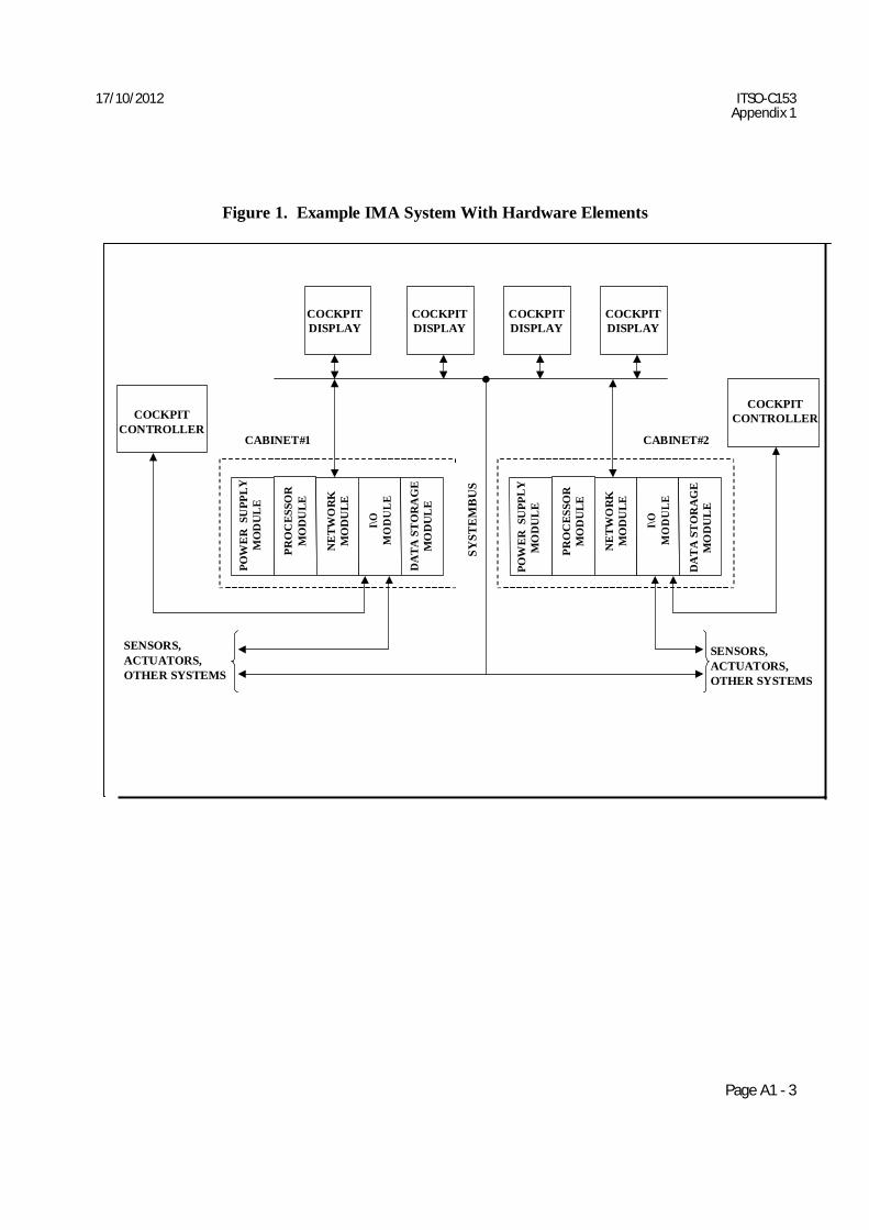
c. Historically, avionics systems consisted of dedicated Line Replaceable Units (LRUs)
which performed specific functions such as auto flight, flight management, and flight deck display. Traditionally, FAA had written TSOs for these LRUs and their functions. Advancements in digital technologies have caused a trend toward higher levels of integration. Software now determines functionality, while the hardware has become a platform for input, output, data storage, and software execution. Since these basic attributes tend to be similar for various applications, the manufacturer can gain efficiencies by using various types of generic airborne hardware elements to execute these functions. Figure 1 shows an example block diagram of an integrated avionics system. Depending upon the requirements of the system application, the types and number of hardware elements chosen and the number of each element type may differ. Figure 1 illustrates an example where the racks or cabinets are populated with modules of various types. Typical module types are processor, power supply, database, and input/output modules. In addition to the racks or cabinets, a complete system may consist of various controllers, displays, and sensors. Any combination of analog signals, dedicated communications busses, or system-level bi-directional communication data buses can provide IMA system communications. Manufacturers may distribute functionality among the modules of one or more racks or cabinets and other equipment.
17/10/2012 ITSO-C153 Appendix 1
Page A1 - 3
POW
ER
SU
PPLY
M
OD
UL
E
PRO
CES
SOR
M
OD
ULE
NE
TWO
RK
M
OD
ULE
I\O
MO
DU
LE
DA
TA S
TO
RA
GE
M
OD
UL
E
SYST
EM
BU
S
POW
ER S
UPP
LY
MO
DU
LE
PRO
CES
SOR
M
OD
ULE
NE
TWO
RK
M
OD
ULE
I\O
MO
DU
LE
DA
TA
ST
OR
AG
E
MO
DU
LE
Figure 1. Example IMA System With Hardware Elements
COCKPIT DISPLAY
COCKPIT DISPLAY
COCKPIT DISPLAY
COCKPIT DISPLAY
COCKPIT
CONTROLLER
CABINET#1 CABINET#2
COCKPIT CONTROLLER
SENSORS, ACTUATORS, OTHER SYSTEMS
SENSORS, ACTUATORS, OTHER SYSTEMS
17/10/2012 ITSO-C153 Appendix 1
Page A1- 4
d. The specific system application function(s) hosted in each hardware element may not be determined or operational until after the manufacturer delivers it, and the user integrates the hardware and software. As a result, the descriptions of aircraft-level functions, their failure condition classifications, and the effects of their loss or malfunction will not be included in the hardware element MPS. Instead, those functions, classifications, and integration will be addressed by pertinent regulations of FAA/DGCA, TSOs/ITSOs, Minimum Operational Performance Specifications (MOPS), and Advisory Circulars. However, the manufacturer’s MPS must state the hardware design assurance and software levels to which each element is developed. The manufacturer must also include in the MPS and data sheet any interfacing hardware and software constraints needed to preserve the stated hardware design assurance and software levels.
e. Hardware elements may include software to enable software loading and/or electronic part marking. Only this kind of software may be approved under this ITSO. If such software is included, it must be developed as per RTCA/DO-178B, Software Considerations in Airborne Systems and Equipment Certification, dated December 1, 1992 to the software level determined by the hardware element manufacturer. 3. MPS OVERVIEW: The MPS developed for each hardware element must address:
a. Intended Function: The manufacturer must specify the intended function of the hardware element in terms of relevant performance requirements over the applicable environments.
b. Assumptions:
(1) Each hardware element by itself may not be capable of performing any function on an aircraft. Aircraft functionality is not realized until multiple hardware elements are integrated and functional software is loaded. Individual hardware elements are intended to be manufactured and shipped separately with only enough software residents to facilitate software loading of the functional software application(s) and/or electronic part marking.
(2) The individual hardware elements should be tested and qualified independent of aircraft functionality. Each element will require its own test procedure to verify that the element performs its intended function over the various environmental conditions. Assurance that the hardware element correctly executes the functional software is not addressed in this ITSO, but must be addressed during the type certificate (TC), supplement type certificate (STC), amended TC (ATC), or amended STC (ASTC) process, or when obtaining functional ITSO authorization.
c. Test Procedures:
(1) Hardware Element Performance Tests: The hardware element manufacturer must develop a test procedure to demonstrate compliance of each applicable hardware element to its MPS, as specified in Section 5 of this Appendix. This test procedure can be performed in a laboratory environment to demonstrate that the hardware element meets the MPS.
(2) Environment Tests: The hardware element manufacturer must develop test
procedures to demonstrate compliance of each hardware element to its MPS during each of
17/10/2012 ITSO-C153 Appendix 1
Page A1- 5
the applicable environments specified in Section 6 of this Appendix. Several test procedures may be required for different environmental tests. The hardware element manufacturer’s equipment specification or test report must detail the test procedures used in environmental testing and must also provide rationale that any use of abbreviated functional tests provides adequate coverage of the performance requirements over the specified operational range.
(3) Installed Hardware Element Tests: The hardware element manufacturer may develop a test procedure used when the hardware element is installed in the aircraft during ground or flight tests. Since the specific aircraft system function(s) hosted by the hardware element is not covered by this Appendix, refer to the respective MPS and/or MOPS for the functional TSO/ITSO test requirements and/or to the manufacturer’s test requirements for any additional aircraft system functions.
(4) Operational Tests: Each hardware element must include design features that
support operational tests to determine that it is functioning properly when installed in the aircraft.
4. GENERAL MPS REQUIREMENTS: Each hardware element MPS must address the following requirements:
a. Airworthiness: The design and manufacture of each hardware element, when
integrated with other hardware elements and the functional software for a particular aircraft, must provide a means of installation that does not impair or degrade the airworthiness of the aircraft.
b. Intended Function: Each hardware element must perform its intended function, as
defined by the manufacturer, when installed in the aircraft or engine.
c. Department of Telecommunications Rules: As a matter of information, if applicable, all equipment must separately comply with the applicable rules of the Wireless Planning and Co-ordination wing, Department of Telecommunications.
d. Fire Protection: Except for small parts (such as knobs, fasteners, seals, grommets,
and small electrical parts) that would not contribute significantly to the propagation of a fire, all material used must be self-extinguishing.
e. Effects of Test: The design of the hardware element and test procedures must be such
that the application of the specified test procedures must not result in any discernible condition that would be detrimental to the performance and reliability of the hardware element manufactured in accordance with such design.
f. Design Assurance: Each hardware element must be developed to the design
assurance level(s) appropriate to the failure condition classifications of its hosted function(s) and the system architecture. An acceptable means for the determination of development assurance levels for systems and design practices can be found in Society of Automotive Engineers (SAE) Aerospace Recommended Practice (ARP) 4754, Certification Considerations for Highly- Integrated or Complex Aircraft Systems. If the hardware element contains electronic devices whose functions cannot be feasibly evaluated by test and/or analysis, the hardware element must comply with RTCA/DO-254, Design Assurance Guidance for Airborne Electronic Hardware. If the hardware element contains software to
17/10/2012 ITSO-C153 Appendix 1
Page A1- 6
enable software loading and/or electronic part marking, the software must be developed to the appropriate software level(s) of RTCA/DO-178B, Software Considerations in Airborne Systems and Equipment Certification.
Note: The design assurance level(s) chosen by the ITSO manufacturer must be compatible with the level(s) assigned to the hardware element software and hardware by the preliminary system safety assessment (PSSA) necessary for the installation of the IMA system.
g. Unused Cabinet or Rack Positions: The manufacturer must define the method and
parts to be used to provide the appropriate covers or position fillers for unused cabinet or rack positions. If required, these parts must be approved as part of the cabinet or rack ITSO authorization.
5. EQUIPMENT PEFORMANCE – STANDARD CONDITIONS:
a. Hardware element performance requirements shall be specified by the manufacturer in
the MPS. However, aircraft functionality is typically not realized until multiple hardware elements are integrated, functional software is loaded, and system integration is accomplished. Additional performance at the aircraft level must also be specified and verified during an aircraft certification program. It is at this higher level that ITSO specifications will be evaluated for compliance. Since this level of performance specification is beyond the scope of this ITSO, it is mentioned here only for completeness. The hardware element manufacturer must prepare MPS for each type of hardware element to which this ITSO is being applied. The contents of each MPS must include all minimum performance requirements for the hardware element. The requirements must be stated in measurable terms. Tolerances must be included in the MPS (where applicable), thereby enabling better test procedure development.
b. Equipment Configuration for Equipment Performance Tests:
(1) The test configuration for cabinet or rack performance tests must include, as a
minimum, the cabinet or rack with all integrated cooling and power supplies, the appropriate power supply modules (if not integrated into the cabinet or rack), the appropriate processing module(s), and the appropriate data communication modules (if not integrated into the cabinet or rack). The test configuration for a module must include, as a minimum, a cabinet or rack that is designed for this module, appropriate power supply modules (if required by the module to function), and appropriate data communication and processing modules (if required by the module to function). All unused module positions in the cabinet or rack must have the appropriate covers or position fillers installed.
(2) The cabinet or rack and module configurations must include the appropriate
interfacing electrical and mechanical connectors intended for the cabinet or rack and modules.
(3) If the hardware elements that are manufactured under this ITSO can be loaded
with software to perform aircraft functions, the manufacturer should use special purpose test software or functional software to demonstrate operation of the hardware element functions. The manufacturer must verify, validate, and control the configuration of the software to ensure the validity of the testing.
17/10/2012 ITSO-C153 Appendix 1
Page A1- 7
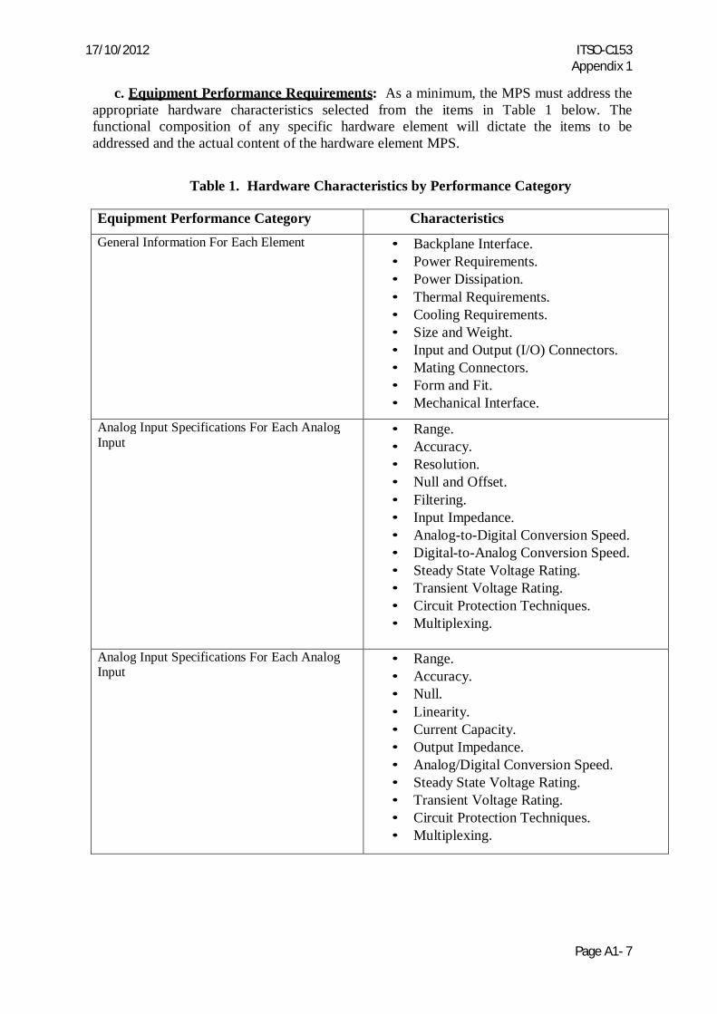
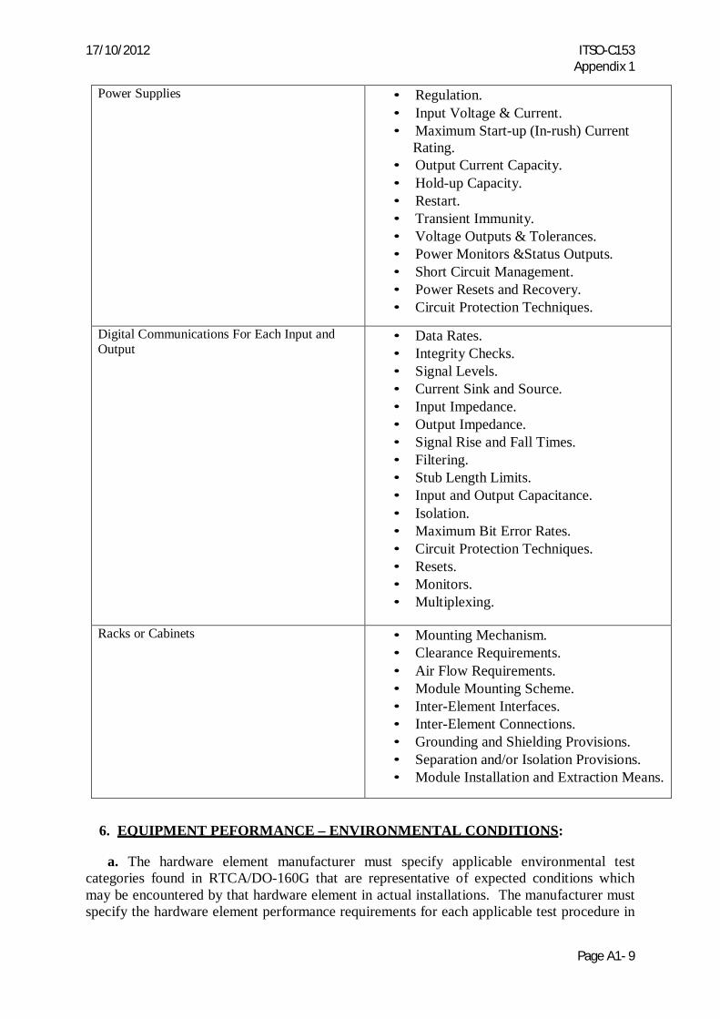
c. Equipment Performance Requirements: As a minimum, the MPS must address the appropriate hardware characteristics selected from the items in Table 1 below. The functional composition of any specific hardware element will dictate the items to be addressed and the actual content of the hardware element MPS.
Table 1. Hardware Characteristics by Performance Category
Equipment Performance Category Characteristics General Information For Each Element • Backplane Interface.
• Power Requirements. • Power Dissipation. • Thermal Requirements. • Cooling Requirements. • Size and Weight. • Input and Output (I/O) Connectors. • Mating Connectors. • Form and Fit. • Mechanical Interface. Analog Input Specifications For Each Analog
Input • Range. • Accuracy. • Resolution. • Null and Offset. • Filtering. • Input Impedance. • Analog-to-Digital Conversion Speed. • Digital-to-Analog Conversion Speed. • Steady State Voltage Rating. • Transient Voltage Rating. • Circuit Protection Techniques. • Multiplexing.
Analog Input Specifications For Each Analog Input
• Range. • Accuracy. • Null. • Linearity. • Current Capacity. • Output Impedance. • Analog/Digital Conversion Speed. • Steady State Voltage Rating. • Transient Voltage Rating. • Circuit Protection Techniques. • Multiplexing.
17/10/2012 ITSO-C153 Appendix 1
Page A1- 8
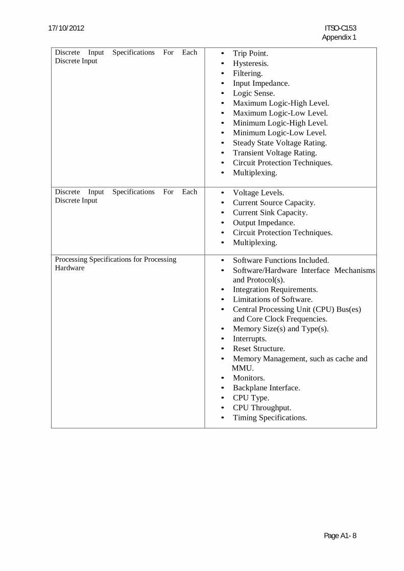
Discrete Input Specifications For Each Discrete Input
• Trip Point. • Hysteresis. • Filtering. • Input Impedance. • Logic Sense. • Maximum Logic-High Level. • Maximum Logic-Low Level. • Minimum Logic-High Level. • Minimum Logic-Low Level. • Steady State Voltage Rating. • Transient Voltage Rating. • Circuit Protection Techniques. • Multiplexing.
Discrete Input Specifications For Each Discrete Input
• Voltage Levels. • Current Source Capacity. • Current Sink Capacity. • Output Impedance. • Circuit Protection Techniques. • Multiplexing.
Processing Specifications for Processing Hardware
• Software Functions Included. • Software/Hardware Interface Mechanisms
and Protocol(s). • Integration Requirements. • Limitations of Software. • Central Processing Unit (CPU) Bus(es)
and Core Clock Frequencies. • Memory Size(s) and Type(s). • Interrupts. • Reset Structure. • Memory Management, such as cache and
MMU. • Monitors. • Backplane Interface. • CPU Type. • CPU Throughput. • Timing Specifications.
17/10/2012 ITSO-C153 Appendix 1
Page A1- 9
Power Supplies • Regulation. • Input Voltage & Current. • Maximum Start-up (In-rush) Current
Rating. • Output Current Capacity. • Hold-up Capacity. • Restart. • Transient Immunity. • Voltage Outputs & Tolerances. • Power Monitors &Status Outputs. • Short Circuit Management. • Power Resets and Recovery. • Circuit Protection Techniques. Digital Communications For Each Input and
Output • Data Rates. • Integrity Checks. • Signal Levels. • Current Sink and Source. • Input Impedance. • Output Impedance. • Signal Rise and Fall Times. • Filtering. • Stub Length Limits. • Input and Output Capacitance. • Isolation. • Maximum Bit Error Rates. • Circuit Protection Techniques. • Resets. • Monitors. • Multiplexing.
Racks or Cabinets • Mounting Mechanism. • Clearance Requirements. • Air Flow Requirements. • Module Mounting Scheme. • Inter-Element Interfaces. • Inter-Element Connections. • Grounding and Shielding Provisions. • Separation and/or Isolation Provisions. • Module Installation and Extraction Means.
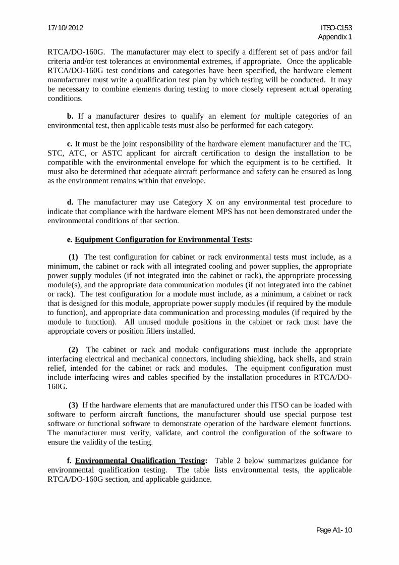
6. EQUIPMENT PEFORMANCE – ENVIRONMENTAL CONDITIONS:
a. The hardware element manufacturer must specify applicable environmental test categories found in RTCA/DO-160G that are representative of expected conditions which may be encountered by that hardware element in actual installations. The manufacturer must specify the hardware element performance requirements for each applicable test procedure in
17/10/2012 ITSO-C153 Appendix 1
Page A1- 10
RTCA/DO-160G. The manufacturer may elect to specify a different set of pass and/or fail criteria and/or test tolerances at environmental extremes, if appropriate. Once the applicable RTCA/DO-160G test conditions and categories have been specified, the hardware element manufacturer must write a qualification test plan by which testing will be conducted. It may be necessary to combine elements during testing to more closely represent actual operating conditions.
b. If a manufacturer desires to qualify an element for multiple categories of an environmental test, then applicable tests must also be performed for each category.
c. It must be the joint responsibility of the hardware element manufacturer and the TC,
STC, ATC, or ASTC applicant for aircraft certification to design the installation to be compatible with the environmental envelope for which the equipment is to be certified. It must also be determined that adequate aircraft performance and safety can be ensured as long as the environment remains within that envelope.
d. The manufacturer may use Category X on any environmental test procedure to
indicate that compliance with the hardware element MPS has not been demonstrated under the environmental conditions of that section.
e. Equipment Configuration for Environmental Tests:
(1) The test configuration for cabinet or rack environmental tests must include, as a
minimum, the cabinet or rack with all integrated cooling and power supplies, the appropriate power supply modules (if not integrated into the cabinet or rack), the appropriate processing module(s), and the appropriate data communication modules (if not integrated into the cabinet or rack). The test configuration for a module must include, as a minimum, a cabinet or rack that is designed for this module, appropriate power supply modules (if required by the module to function), and appropriate data communication and processing modules (if required by the module to function). All unused module positions in the cabinet or rack must have the appropriate covers or position fillers installed.
(2) The cabinet or rack and module configurations must include the appropriate interfacing electrical and mechanical connectors, including shielding, back shells, and strain relief, intended for the cabinet or rack and modules. The equipment configuration must include interfacing wires and cables specified by the installation procedures in RTCA/DO-160G.
(3) If the hardware elements that are manufactured under this ITSO can be loaded with software to perform aircraft functions, the manufacturer should use special purpose test software or functional software to demonstrate operation of the hardware element functions. The manufacturer must verify, validate, and control the configuration of the software to ensure the validity of the testing.
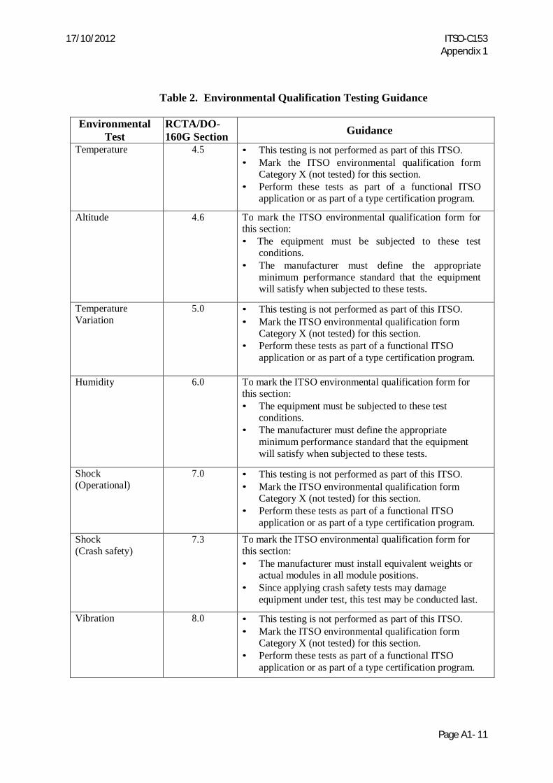
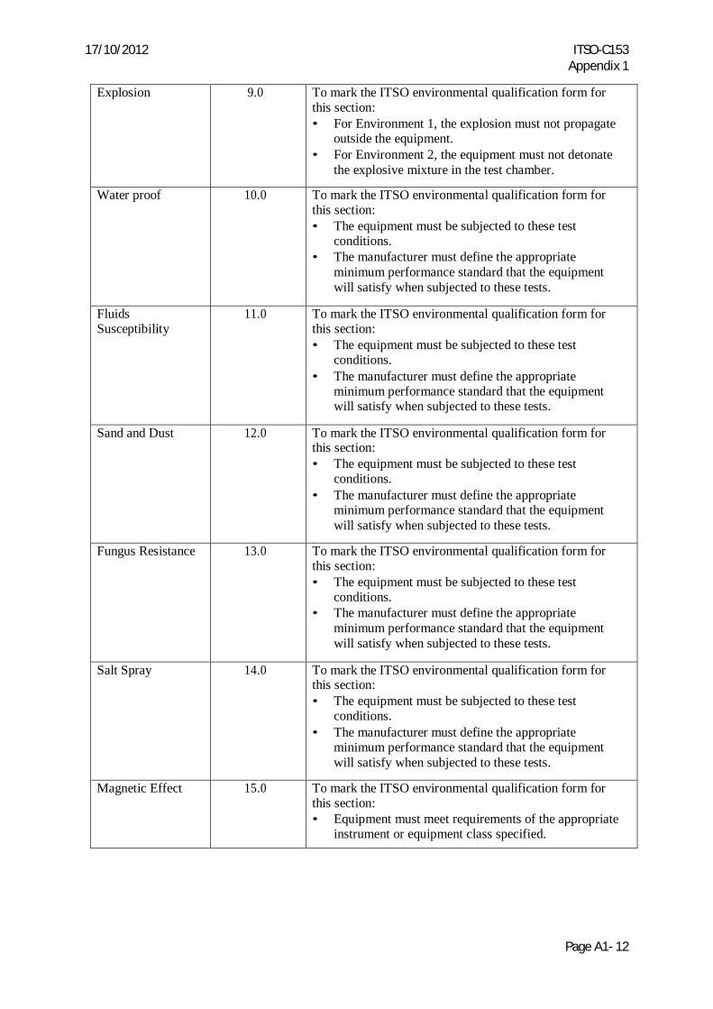
f. Environmental Qualification Testing: Table 2 below summarizes guidance for environmental qualification testing. The table lists environmental tests, the applicable RTCA/DO-160G section, and applicable guidance.
17/10/2012 ITSO-C153 Appendix 1
Page A1- 11
Table 2. Environmental Qualification Testing Guidance
Environmental Test
RCTA/DO- 160G Section
Guidance
Temperature 4.5 • This testing is not performed as part of this ITSO. • Mark the ITSO environmental qualification form
Category X (not tested) for this section. • Perform these tests as part of a functional ITSO
application or as part of a type certification program. Altitude 4.6 To mark the ITSO environmental qualification form for this section: • The equipment must be subjected to these test
conditions. • The manufacturer must define the appropriate
minimum performance standard that the equipment will satisfy when subjected to these tests.
Temperature Variation
5.0 • This testing is not performed as part of this ITSO. • Mark the ITSO environmental qualification form
Category X (not tested) for this section. • Perform these tests as part of a functional ITSO
application or as part of a type certification program.
Humidity 6.0 To mark the ITSO environmental qualification form for this section: • The equipment must be subjected to these test
conditions. • The manufacturer must define the appropriate
minimum performance standard that the equipment will satisfy when subjected to these tests.
Shock (Operational)
7.0 • This testing is not performed as part of this ITSO. • Mark the ITSO environmental qualification form
Category X (not tested) for this section. • Perform these tests as part of a functional ITSO
application or as part of a type certification program. Shock (Crash safety)
7.3 To mark the ITSO environmental qualification form for this section: • The manufacturer must install equivalent weights or
actual modules in all module positions. • Since applying crash safety tests may damage
equipment under test, this test may be conducted last.
Vibration 8.0 • This testing is not performed as part of this ITSO. • Mark the ITSO environmental qualification form
Category X (not tested) for this section. • Perform these tests as part of a functional ITSO
application or as part of a type certification program.
17/10/2012 ITSO-C153 Appendix 1
Page A1- 12
Explosion 9.0 To mark the ITSO environmental qualification form for this section: • For Environment 1, the explosion must not propagate
outside the equipment. • For Environment 2, the equipment must not detonate
the explosive mixture in the test chamber.
Water proof 10.0 To mark the ITSO environmental qualification form for this section: • The equipment must be subjected to these test
conditions. • The manufacturer must define the appropriate
minimum performance standard that the equipment will satisfy when subjected to these tests.
Fluids Susceptibility
11.0 To mark the ITSO environmental qualification form for this section: • The equipment must be subjected to these test
conditions. • The manufacturer must define the appropriate
minimum performance standard that the equipment will satisfy when subjected to these tests.
Sand and Dust 12.0 To mark the ITSO environmental qualification form for this section: • The equipment must be subjected to these test
conditions. • The manufacturer must define the appropriate
minimum performance standard that the equipment will satisfy when subjected to these tests.
Fungus Resistance 13.0 To mark the ITSO environmental qualification form for this section: • The equipment must be subjected to these test
conditions. • The manufacturer must define the appropriate
minimum performance standard that the equipment will satisfy when subjected to these tests.
Salt Spray 14.0 To mark the ITSO environmental qualification form for this section: • The equipment must be subjected to these test
conditions. • The manufacturer must define the appropriate
minimum performance standard that the equipment will satisfy when subjected to these tests.
Magnetic Effect 15.0 To mark the ITSO environmental qualification form for this section: • Equipment must meet requirements of the appropriate
instrument or equipment class specified.
17/10/2012 ITSO-C153 Appendix 1
Page A1- 13
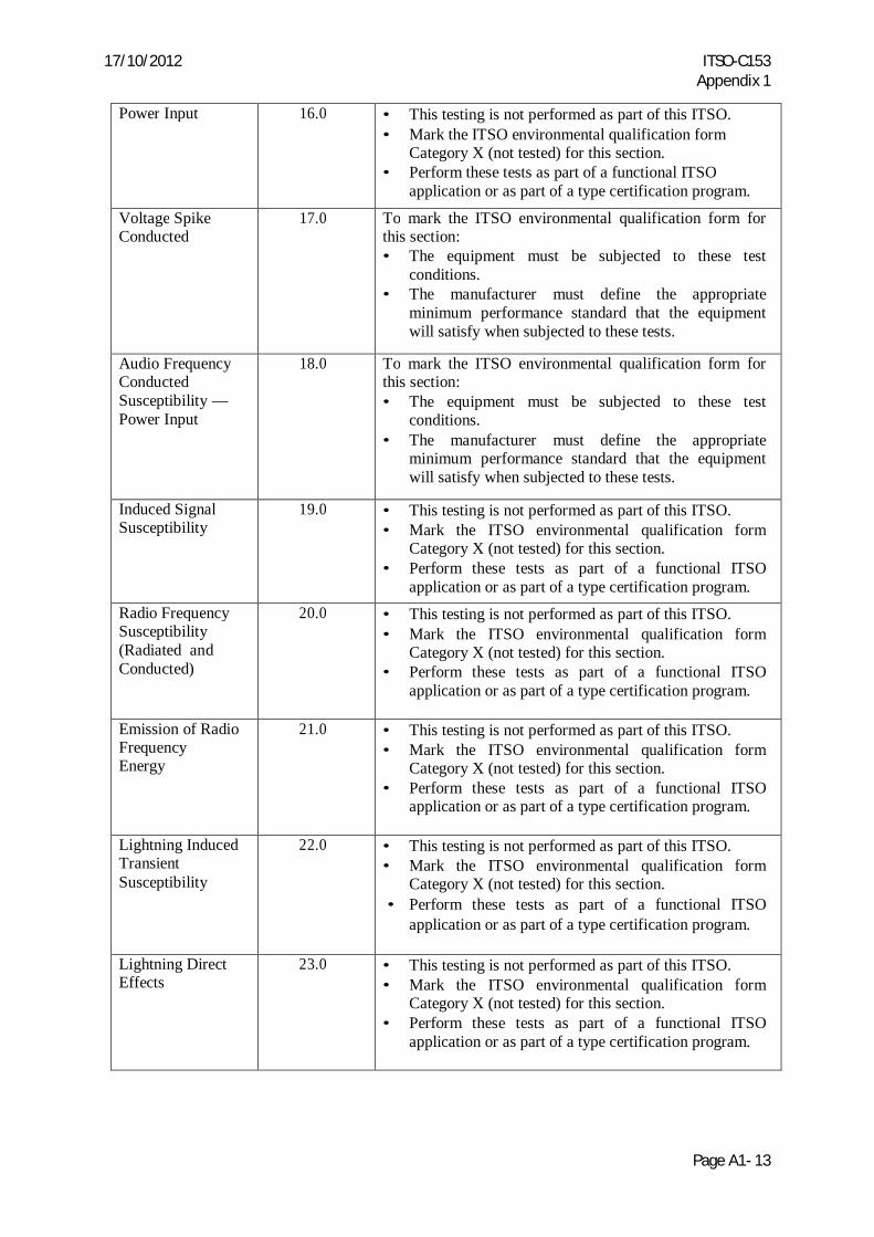
Power Input 16.0 • This testing is not performed as part of this ITSO. • Mark the ITSO environmental qualification form
Category X (not tested) for this section. • Perform these tests as part of a functional ITSO
application or as part of a type certification program.
Voltage Spike Conducted
17.0 To mark the ITSO environmental qualification form for this section: • The equipment must be subjected to these test
conditions. • The manufacturer must define the appropriate
minimum performance standard that the equipment will satisfy when subjected to these tests.
Audio Frequency Conducted Susceptibility — Power Input
18.0 To mark the ITSO environmental qualification form for this section: • The equipment must be subjected to these test
conditions. • The manufacturer must define the appropriate
minimum performance standard that the equipment will satisfy when subjected to these tests.
Induced Signal Susceptibility
19.0 • This testing is not performed as part of this ITSO. • Mark the ITSO environmental qualification form
Category X (not tested) for this section. • Perform these tests as part of a functional ITSO
application or as part of a type certification program. Radio Frequency Susceptibility (Radiated and Conducted)
20.0 • This testing is not performed as part of this ITSO. • Mark the ITSO environmental qualification form
Category X (not tested) for this section. • Perform these tests as part of a functional ITSO
application or as part of a type certification program.
Emission of Radio Frequency Energy
21.0 • This testing is not performed as part of this ITSO. • Mark the ITSO environmental qualification form
Category X (not tested) for this section. • Perform these tests as part of a functional ITSO
application or as part of a type certification program.
Lightning Induced Transient Susceptibility
22.0 • This testing is not performed as part of this ITSO. • Mark the ITSO environmental qualification form
Category X (not tested) for this section. • Perform these tests as part of a functional ITSO
application or as part of a type certification program.
Lightning Direct Effects
23.0 • This testing is not performed as part of this ITSO. • Mark the ITSO environmental qualification form
Category X (not tested) for this section. • Perform these tests as part of a functional ITSO
application or as part of a type certification program.
17/10/2012 ITSO-C153 Appendix 1
Page A1- 14
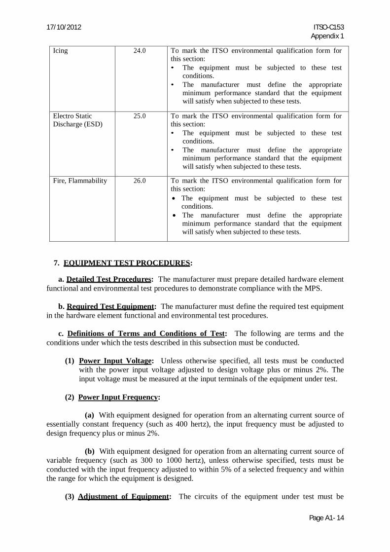
Icing 24.0 To mark the ITSO environmental qualification form for this section: • The equipment must be subjected to these test
conditions. • The manufacturer must define the appropriate
minimum performance standard that the equipment will satisfy when subjected to these tests.
Electro Static Discharge (ESD)
25.0 To mark the ITSO environmental qualification form for this section: • The equipment must be subjected to these test
conditions. • The manufacturer must define the appropriate
minimum performance standard that the equipment will satisfy when subjected to these tests.
Fire, Flammability 26.0 To mark the ITSO environmental qualification form for this section: The equipment must be subjected to these test
conditions. The manufacturer must define the appropriate
minimum performance standard that the equipment will satisfy when subjected to these tests.
7. EQUIPMENT TEST PROCEDURES:
a. Detailed Test Procedures: The manufacturer must prepare detailed hardware element functional and environmental test procedures to demonstrate compliance with the MPS.
b. Required Test Equipment: The manufacturer must define the required test equipment in the hardware element functional and environmental test procedures.
c. Definitions of Terms and Conditions of Test: The following are terms and the conditions under which the tests described in this subsection must be conducted.
(1) Power Input Voltage: Unless otherwise specified, all tests must be conducted with the power input voltage adjusted to design voltage plus or minus 2%. The input voltage must be measured at the input terminals of the equipment under test.
(2) Power Input Frequency:
(a) With equipment designed for operation from an alternating current source of
essentially constant frequency (such as 400 hertz), the input frequency must be adjusted to design frequency plus or minus 2%.
(b) With equipment designed for operation from an alternating current source of variable frequency (such as 300 to 1000 hertz), unless otherwise specified, tests must be conducted with the input frequency adjusted to within 5% of a selected frequency and within the range for which the equipment is designed.
(3) Adjustment of Equipment: The circuits of the equipment under test must be
17/10/2012 ITSO-C153 Appendix 1
Page A1- 15
properly aligned and otherwise adjusted or calibrated per the manufacturer’s recommended practices prior to application of the specified tests.
(4) Test Equipment: All equipment used in the performance of the tests must be identified by make, model, and serial number (where appropriate), and its latest calibration date. When appropriate, test equipment calibration standards must be traceable to national and/or international standards.
(5) Test Instrument Precautions: Precautions must be taken during the tests to prevent the introduction of errors resulting from the connection of voltmeters, oscilloscopes, and other test instruments across the input and output impedance of the equipment under test.
(6) Ambient Conditions: Unless otherwise specified, all tests must be conducted under condition of ambient room temperature, pressure, and humidity. However, the room temperature must not be lower than 10 degrees Celsius.
(7) Connected Loads: Unless otherwise specified, all tests must be performed with the equipment connected to loads having the nominal impedance values for which it is designed. 8. INSTALLED EQUIPMENT PERFORMANCE: By nature of the architecture and application of individual hardware elements whose specifications comply with Sections 4 through 7 of this Appendix, these hardware elements typically must be installed and integrated with other equipment in order to provide system-level or aircraft-level functionality. When software is loaded into hardware elements to provide resources for system-level functionality, it is necessary to demonstrate hardware and software integration, integration of the system into the aircraft, and integration of the system with other interfacing aircraft systems. The applicant for the type certificate must demonstrate that hardware elements, as installed in the aircraft, meet the applicable regulations. 9. EQUIPMENT OPERATIONAL PERFORMANCE CHARACTERISTICS: To ensure that operations can be conducted safely and reliably in the expected operational environment, the individual hardware elements typically must be installed and integrated with other equipment in order to provide system-level or aircraft-level functionality. The installed system must annunciate to the flight crew, when any hardware element is not capable of performing its intended functions.

17/10/2012 ITSO-C153 Appendix 2
Page A2- 1
APPENDIX 2
SAMPLE FORMAT FOR DATA SHEET
FOR
INTEGRATED MODULAR AVIONICS (IMA) HARDWARE ELEMENTS
17/10/2012 ITSO-C153 Appendix 2
Page A2- 2
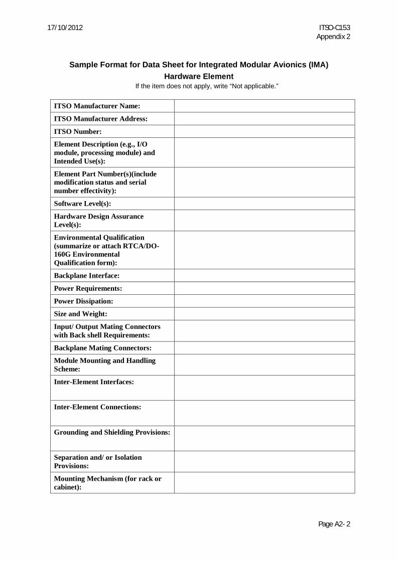
Sample Format for Data Sheet for Integrated Modular Avionics (IMA)
Hardware Element If the item does not apply, write “Not applicable.”
ITSO Manufacturer Name:
ITSO Manufacturer Address:
ITSO Number:
Element Description (e.g., I/O module, processing module) and Intended Use(s):
Element Part Number(s)(include modification status and serial number effectivity):
Software Level(s):
Hardware Design Assurance Level(s):
Environmental Qualification (summarize or attach RTCA/DO- 160G Environmental Qualification form):
Backplane Interface:
Power Requirements:
Power Dissipation:
Size and Weight:
Input/ Output Mating Connectors with Back shell Requirements:
Backplane Mating Connectors:
Module Mounting and Handling Scheme:
Inter-Element Interfaces:
Inter-Element Connections:
Grounding and Shielding Provisions:
Separation and/ or Isolation Provisions:
Mounting Mechanism (for rack or cabinet):
17/10/2012 ITSO-C153 Appendix 2
Page A2- 3
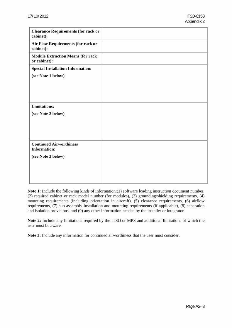
Clearance Requirements (for rack or cabinet):
Air Flow Requirements (for rack or cabinet):
Module Extraction Means (for rack or cabinet):
Special Installation Information:
(see Note 1 below)
Limitations:
(see Note 2 below)
Continued Airworthiness Information:
(see Note 3 below)
Note 1: Include the following kinds of information:(1) software loading instruction document number, (2) required cabinet or rack model number (for modules), (3) grounding/shielding requirements, (4) mounting requirements (including orientation in aircraft), (5) clearance requirements, (6) airflow requirements, (7) sub-assembly installation and mounting requirements (if applicable), (8) separation and isolation provisions, and (9) any other information needed by the installer or integrator. Note 2: Include any limitations required by the ITSO or MPS and additional limitations of which the user must be aware. Note 3: Include any information for continued airworthiness that the user must consider.
17/10/2012 ITSO-C153 Appendix 3
Page A3- 1
APPENDIX 3
HARDWARE ELEMENT DEFINITIONS
17/10/2012 ITSO-C153 Appendix 3
Page A3- 2
This appendix summarizes the terminology applicable to this ITSO, hardware element development, and application of Appendix 1 MPS development criteria. The terms are segregated into eight categories as per the appropriate hardware element performance.
(1) General Terms:
Air Flow Requirements: Specific requirements to provide air movement into or onto a cabinet, LRU, or module (for example, air temperature, volume rate, and pressure) Analog/Digital Conversion Speed: The time to perform one Analog-to-Digital (A-to-D) conversion. Typically, this is expressed as either the time for one analog conversion by the A-to-D converter device or the frequency at which all analog inputs are converted. Circuit Protection Techniques: The electrical isolation or circuitry included on inputs or outputs to protect the functional circuits from external environments. An example is using transorbs to protect circuits from the indirect effects of lightning. Current Source/Sink: The maximum current drawn by the output while pulling the signal to a zero volt (ground) level. Current Source: The maximum current supplied by the output while driving the signal to a voltage level. Clearance Requirements: Additional spacing requirements in specific directions from the cabinet or rack beyond the outline dimensions. One example of this additional clearance is the area to allow proper airflow. Design Assurance: All planned and systematic actions and data used to substantiate that hardware correctly performs its intended function(s) and that design errors have been identified and corrected such that the hardware satisfies the applicable certification basis. Development Assurance: All planned and systematic actions and data used to substantiate that the system performs its intended function and that development errors have been identified and corrected such that the system satisfies the applicable certification basis. Functional Software: Software applications that will be approved as part of a functional ITSO authorization or as part of a type certification effort. This software is sometimes referred to as operational software, application software, or flight software. Functional TSO/ITSO: A TSO/ITSO with a defined functionality (for example, a Global Positioning System, TSO-C129a). TSO/ITSO-C153 is not considered a functional TSO/ITSO, because IMA hardware elements typically do not have system-level functionality. Grounding / Shielding Provisions: The electrical and/or mechanical details of the design which provide grounding of the element or which provide shield connections. These are the design details usually associated with the Radio Frequency emission and susceptibility protection of the system. Hardware Element: In this ITSO, a hardware element is: (1) a hardware module, or (2)
17/10/2012 ITSO-C153 Appendix 3
Page A3- 3
cabinets or racks that host hardware modules.
Note: This definition may differ from terminology in other documents (for example, RTCA/DO-254).
Inter-Element Connections: The connector type specification and connector pin assignments specified to allow modules to be installed interchangeably in the cabinets or racks.
Inter-Element Interfaces: The definition of the electrical signals, timing requirements, and protocols used to communicate among modules or elements with the cabinet or system. Module Extraction Means: The details of the mechanical design to enable removal of the module from the cabinet. Module Mounting Scheme: The details of the mechanical design used to secure each module into the cabinet or rack. Mounting Mechanism: The details of the mechanical mechanism(s) used to secure the module into the cabinet or rack on the aircraft. Multiplexing: The design technique where multiple inputs are individually switched to one receiver (for example, multiple digital communication buses switched to serial receiver) or multiple outputs are individually supplied by the same circuit (for example, multiple analog outputs driven by one Digital-to-Analog converter through multiple sample-and-holds). Separation/Isolation Provisions: The electrical and/or mechanical details of the design which provide physical or electrical means of reducing interference from one element to another. Steady State Voltage Rating: The maximum voltage range that can be applied continuously to an input or output without resulting in damage.
Transient Voltage Rating: The maximum voltage that can be applied for a short period of time to an input or output without resulting in damage. The maximum duration of the transient must be included.
(2) Analog Input/ Output Terms:
Accuracy: The degree of conformity to the true value of the signal. This is usually expressed as a percentage of the reading or a percentage of the full-scale value of the signal.
Current Capacity: The maximum amount of current that can be sinked or sourced by the circuit. Linearity: The error from the directly proportional expected value of the signal as the signal values vary over the entire range.
17/10/2012 ITSO-C153 Appendix 3
Page A3- 4
Null: The values of the signal for which a value of zero is identified. This is usually shown as positive and negative voltage values.
Offset: The indicated value of the signal (usually non-zero) when zero volts is applied. Range: The least and greatest operating voltage extremes (full scale) of the signal; the voltage extremes between which the value of the signal is valid. Resolution: The smallest measurable division of the numerical expression of the signal. This is usually identified as the number of binary bits used to express the value of the signal and/or the value in volts of the least significant binary bit (LSB).
(3) Discrete Input/ Output Terms.
Discrete Input: This is an input with only two states. Typical examples are “ground or open” and “28 volt and open” inputs. Discrete Output: An output with only two states. Typical examples are “ground or open” and “28 volt and open” outputs.
(4) Input Terms:
Hysteresis: The value of the input voltage lag when changing states. For example, if an input circuit has 0.2 volts of hysteresis and if the trip point is 2.0 volts then the circuit will change state as the input voltage reaches 2.0 volts but will not revert back to the original state until the input voltage drops below 1.8 volts. Logic Sense: This is the functional interpretation of the discrete input states. A true or positive logic sense may identify the “ground” state as a ‘low” or binary “0”. An inverse or negative logic sense may identify a “ground” state as a “high” or binary “1”. Maximum Logic-High Level: The largest voltage value that can be connected to the input for which the circuit will interpret as “high”. Maximum Logic-Low Level: The largest voltage value that can be connected to the input for which the circuit will interpret as “low”. Minimum Logic-High Level: The smallest voltage value that can be connected to the input for which the circuit will interpret as “high”. Minimum Logic-Low Level: The smallest voltage value that can be connected to the input for which the circuit will interpret as “low”. Trip Point: This is the input voltage value at which the input circuitry changes state.
(5) Output Terms:
Current Sink Capacity: The maximum current drawn by the output while pulling the signal to a zero volt (ground) level (current flowing in the direction from the load to the element output).
17/10/2012 ITSO-C153 Appendix 3
Page A3- 5
Current Source Capacity: The maximum current supplied by the output while driving the signal to a voltage level (current flowing in the direction from the element output to the load). Voltage Levels: The minimum and maximum voltages for each state of the output. The ground point that is to be used as the reference must be identified.
(6) Processor Terms:
Backplane Interface: The definition of the electrical signals, buses, timing requirements, and protocols used to communicate among elements installed in a cabinet or rack. Interrupts: The signals to the processor that stops execution of an ongoing process or application. These announce that a higher priority or asynchronous event is occurring. Memory Management Unit: A specialized control circuitry, sometimes integrated within the microprocessor, which performs predictive reads of instruction (pre-fetch) for use by the processor. It also may perform structured or prioritized control of specific sections of memory. Monitors: Specific circuits which observe the normal operation of the processing system and alert the processor or user of an abnormal condition. Examples are power supply monitors, which reset the processor when a voltage is outside ofits tolerance, and activity monitors which reset the processor when the processor is not performing a prescribed sequence. Reset Structure: The architectural details of the various signals that stop execution of an ongoing process, or software application. They then restart the processor at a known state.
Central Processing Unit (CPU) Throughput: A measure of the number of processor instructions completed by the CPU per unit of time.
(7) Power Supply Terms:
Hold-up Capacity: The capacity of the power supply to continue supplying output current after the input voltage drops below the minimum level. This is usually expressed as the time from the input voltage drop to the reset generated by the power supply to the processor.
Input Voltage & Current: The input voltage is specified as nominal and acceptable variation values. The input current is specified as maximum steady state current. For peak current see “in-rush current” below. Maximum Start-up (In-rush) Current Rating: The maximum input current when the power supply is first becoming active as a result of the input voltage increasing to the minimum level. Output Current Capacity: The continuously operating maximum current supplied for each output voltage.
17/10/2012 ITSO-C153 Appendix 3
Page A3- 6
Power Monitors & Status Outputs: Separate circuitry which checks the output voltage levels and current loading of the power supply. This circuitry will generate one or more binary signals that may be connected to the processor to alert it to the “out of spec” condition. These binary signals may also force the power supply to shut-down to prevent damage to power supply components. Power Resets: A binary signal output from the power supply that is asserted when the output voltages are outside acceptable tolerances. Regulation: The percentage of variation of the output voltages when subjected to changes in load, changes in temperature, and all input voltage transients and deviations. Restart: The ability of the power supply or other circuit to return to the normal operating mode when the input voltage returns to or above the minimum level or when the tripped monitor indicates the “out-of-spec” condition has returned to normal.
Short Circuit Management: The circuitry that monitors for short circuits or over-current conditions in the power supply outputs. The results from this circuitry may shut down the affected output or the entire power supply. Transient Immunity: The ability of the power supply to continue operating normally during variations in the input voltage. This is usually expressed as the length of time and the voltage level of the transient. Voltage Outputs & Tolerances: The voltage levels and tolerances of the outputs produced by the power supply.
(8) Digital Communication Terms:
Data Rates: The number of data bits transmitted in a time period. This is usually expressed in thousands of bits per second (Kbps) or millions of bits per second (Mbps). Integrity Checks: The process that uses additional data accompanying the message information to validate that the message data was received without corruption or contamination. Examples are parity checks, checksums, data validity checks, and cyclic redundancy checks. Maximum Bit Error Rates: The largest number of bit errors allowed in a message transmission before the receiver invalidates its ability to receive data from that source. Monitors: Separate circuitry that checks either the continuing operation of a transmitter, or checks that the receiver responds to input data. This circuitry will generate one or more binary signals that may be connected to the processor, alerting it to the “failed” condition. Resets: Conditions that result in the receiver or transmitter stopping operation, clearing all data, and restarting. Signal Levels: The minimum and maximum voltages for each state of the input or output. Typically, tolerances, thresholds, and reference ground point are also identified.
17/10/2012 ITSO-C153 Appendix 3
Page A3- 7
Signal Rise and Fall Times: The signal rise time is the time for the output to transition from10% of the amplitude to 90% of the amplitude. The signal fall time is the time for the output to transition from the 90% level to the 10% level. Stub Length Limits: The minimum and maximum length requirements of the wiring connector from the main bus to the inputs of the element.