Embed Size (px)
Citation preview

1
ITSO - Basics of Satellite
Communications
Nishaal Goure Sunkurh
17 July 2017
2
Introduction
• Nishaal Goure Sunkurh
• Customer Solutions Engineer at Intelsat
• Based in the Sandton Office in Johannesburg
• Tel: +27 11 535 4700
• E-mail: [email protected]
Guidelines• Mobile Phones: Kindly switch to Silent Mode
• Please ask questions
3
Contents
• Introduction to Satellite Communications
• Satellite Economics
• Satellite Network Design
• Satellite Earth Station Equipment
• Digital Communications Techniques
• Modulation
• Technology Trends

4
Introduction to Satellite
Communications

5
What is a Telecommunications Satellite?
• A telecommunications satellite is a complex machine located in outer space
that:
• Receives signals from the Earth
• Converts, amplifies and sends signals back down to the Earth
• Reaches millions of locations at the same time
• A telecommunications satellite comprises of:
• A platform (or bus) which includes the propulsion system, fuel tanks, batteries, solar panels,
attitude and orbit control functions, etc.
• A payload of antennas, amplifiers, frequency converters, etc

6
Basis Telecommunications Satellite template
Solar Arrays for
Electrical Power
Communications
Payload
Communications
Antennas
Spacecraft Control/Propulsion
Earth Deck with
Global Beam, Telemetry
And Command Antennas

7
First types of Telecommunications Satellites
Telstar 1 (1962) Intelsat 801 (1997)

8
Telecommunications Satellite Today
IS-35e (2017) IS-33e (2016)

9
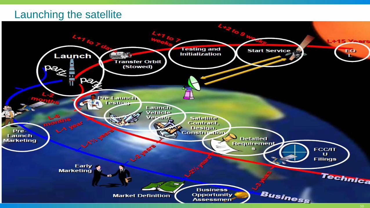
Satellite Economics:
Building and Launching a Telecommunications Satellite
• It takes about 3 years to get a GEO telecom satellite built and launched
• Satellite payloads are customized for a given mission
• Satellites are heavily tested on the ground in facilities that reproduce the space
environment:
▪ Mechanical, Thermal, Noise and RF tests
• Typical cost of a satellite is $150-$250 million
▪ Some satellites can cost as much as $500 million
▪ Not including launch services ($55-$100 million) and insurance
10
Launching the satellite

11
Orbital Slots
• Consultation with the ITU for an orbital slot
• Orbital slots are “owned” by the regional country
• In orbital arc of 360°, theoretically there are 360 parking bays for satellites.
• Satellites are co-located in the orbital slots
• Coordination is done so that the frequency, polarisation and other technical parameters
do not clash.
• Within the allocated orbital slot the operator is allocated a frequency of use
at the slot : C; Ku or Ka etc

12
Approximately 50 satellites plus IntelsatOne, a fully-integrated ground infrastructure
incorporating teleports, points of presence and IP/MPLS fiber network
The Intelsat Globalized Network Infrastructure
13
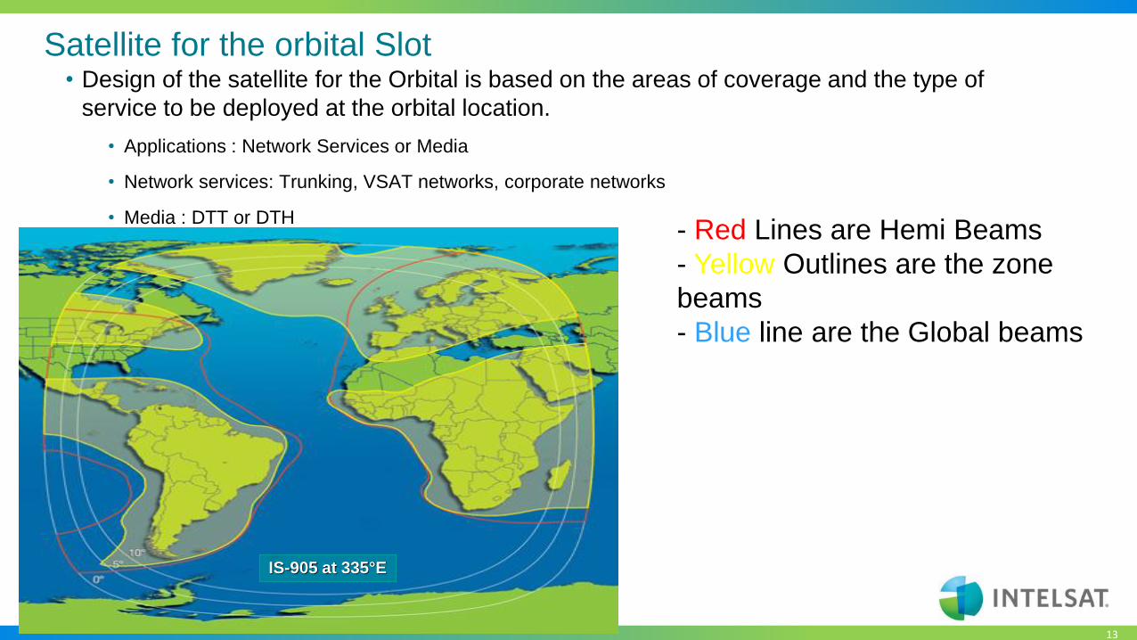
Satellite for the orbital Slot• Design of the satellite for the Orbital is based on the areas of coverage and the type of
service to be deployed at the orbital location.
• Applications : Network Services or Media
• Network services: Trunking, VSAT networks, corporate networks
• Media : DTT or DTH
IS-905 at 335°E
- Red Lines are Hemi Beams
- Yellow Outlines are the zone
beams
- Blue line are the Global beams
14
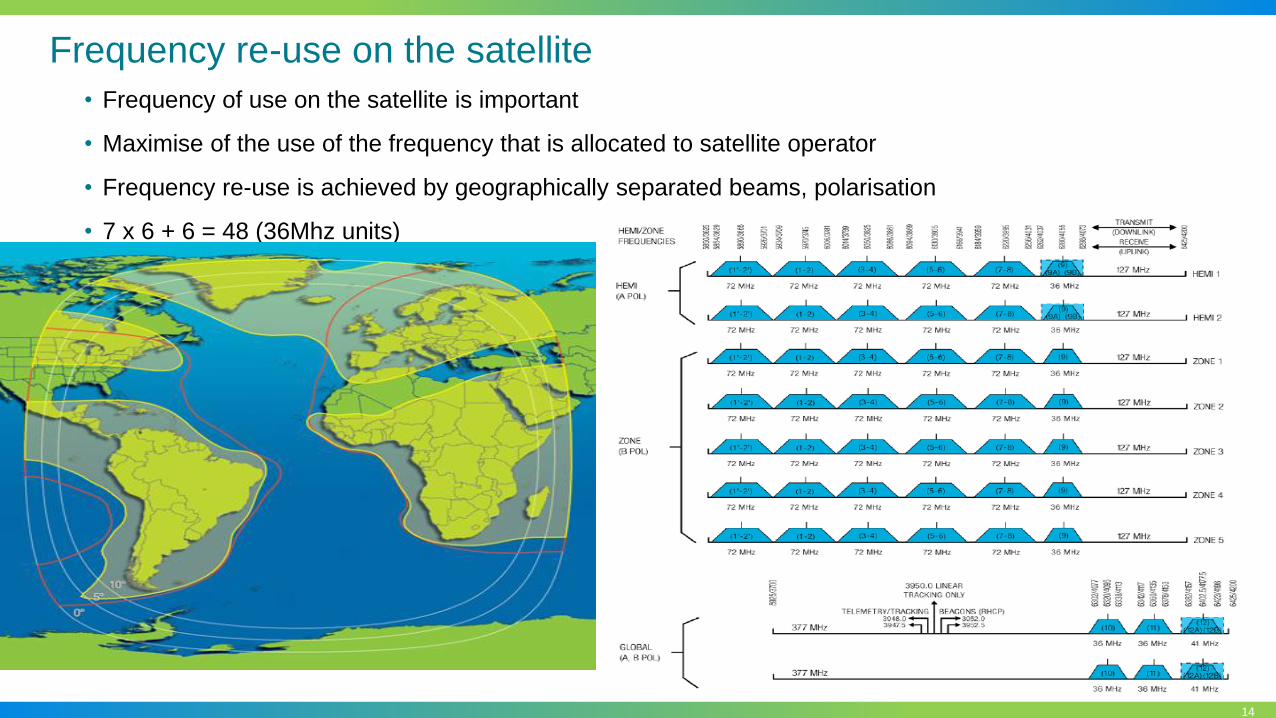
Frequency re-use on the satellite
• Frequency of use on the satellite is important
• Maximise of the use of the frequency that is allocated to satellite operator
• Frequency re-use is achieved by geographically separated beams, polarisation
• 7 x 6 + 6 = 48 (36Mhz units)

15
Typical Satellite Coverage
Coverage areas depend on the satellite type and targeted services
IS-905 C-band
Zone beams
IS-23 C-band
Hemi beam
IS-14 Ku-band
Zone beams

16
Typical Satellite Coverage
Intelsat’s next generation EpicNG satellite coverage
IS-35e C-band
Spot Beams (2017)
IS-33e Ku-band
Spot beams (2016)

17
Key Applications of Satellite Communications
Network
Services
Media
Services
Government
Services
ISRMilitary Mobility
Hosted Payloads
End-to-End Communications
Embassy Networks
Space Situational Awareness
DTHCable
DistributionMCPC Platforms Special Events Satellite News
GatheringMobile Video
Cell BackhaulMaritime
CommunicationsOil & Gas Aeronautical Disaster
RecoveryEnterprise
18
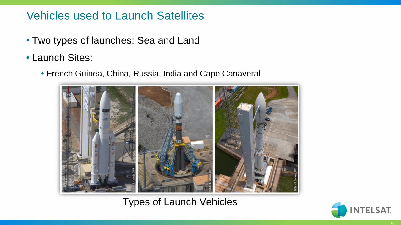
Vehicles used to Launch Satellites
• Two types of launches: Sea and Land
• Launch Sites:
• French Guinea, China, Russia, India and Cape Canaveral
Types of Launch Vehicles

19
Satellite Launch: IS-33e and IS-36
• IS-33e and IS-36 was launched on the 24th August 2017

20
Satellite Earth Station
Equipment

21
Satellite Earth Station Equipment
• Antenna
• Types
• Parameters
• Uplink
• Modulation
• Up-Converters
• Transmitters
• Inter Facilities Link
• RF Downlink
• LNA / LNB
• Down-convetors
• Demodulation
• Inter Facilities Link

22
Antenna
• What is an antenna
• An antenna is a metallic structure that captures and/or transmits radio
electromagnetic waves. Antennas come in all shapes and sizes from little
ones that can be found on your roof to watch TV to really big ones that
capture signals from satellites millions of miles away.
• The antennas that Satellite Communications use are special bowl shaped
that focuses signals at a single point called a parabolic antenna. The bowl
shape is what allows the antennas to both capture and transmit
electromagnetic waves. These antennas move horizontally (measured in
hour angle/declination) and vertically (measured in azimuth/elevation) in
order to capture and transmit the signal.
23
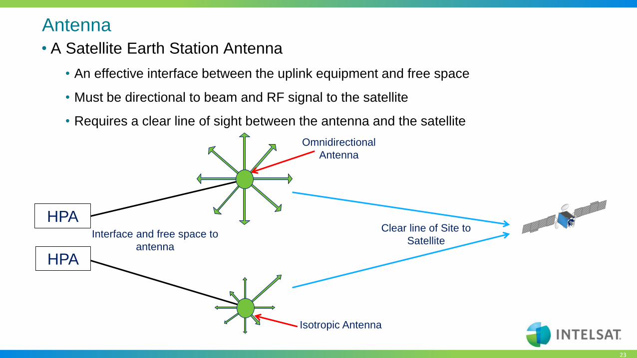
Antenna
• A Satellite Earth Station Antenna
• An effective interface between the uplink equipment and free space
• Must be directional to beam and RF signal to the satellite
• Requires a clear line of sight between the antenna and the satellite
HPA
HPA
Omnidirectional
Antenna
Isotropic Antenna
Clear line of Site to
SatelliteInterface and free space to
antenna

24
Antenna
• Antenna Parameters
• Gain
• G(dBi) = 20.4 + 20 Log f + 20 Log D + 10 Log h
• f = frequency in GHz,
• D = Diameter in meters,
• h = Antenna Efficiency in Decimal format
• What should the be the gain of a 9.3m C-band antenna at 6.4 GHz that is at 62% efficiency?
• G = 20.4 + 20 Log 6.4 + 20 Log 9.3 + 10 Log 0.62
• G = 20.4 + 20 (0.806179) + 20 (0.968482) + 10 (-0.2076)
• G = 20.4 + 16.12 + 19.37 + -2.08
• G = 53.81 dBi

25
Antenna
• Antenna Beamwidth:
• For a given antenna, the higher the frequency the narrower the 3dB beamwidth. Therefore
the receive band will be broader than the transmit.
• For a given frequency band, the larger the antenna aperture the smaller or narrow the
beamwidth.
•𝜃 (𝑑𝑒𝑔. ) =21
𝑓𝐷
• f = frequency in GHz,
• D = Diameter in meters,

26
Antenna
• Antenna Beamwidth
32m Antenna 4.5m Antenna
The rectangular box shows the positional
limits for a satellite in geostationary orbit, in
relation to beams from a 32m antenna and
4.5 antenna

27
Antenna
• Antenna Types
• Fixed
• Manual Movement
• Provides coverage of the entire satellite arc
• Peaked on satellite with no further adjustments
• Limited Motion
• Typically Motorized
• Azimuth ± 60˚ from antenna center line (CL)
• Elevation: 5˚ to 90˚
• Ability to track satellites Incline orbit satellites
• Ability to change to different satellite orbital location
• Full Motion
• Motorized
• Azimuth ± 180˚ from antenna center line (CL)
• Elevation: 5˚ to 90˚
• Ability to track satellites in transfer orbit

28
Antenna
• Antenna Position Controllers (APC)
• Installed at base of the antenna (“Jog Controller”)
• Toggle switches for AZ (CW/CCW), EL (Up/Down) and Polarizer
• Serial data link for remote control with a computer
• Transducers provide AZ & EL and Polarizer angle readouts

29
Antenna
• Antenna Control Unit (ACU)
• Manually position and polarize the antenna
• Preset satellite locations stored in memory
• Step Track
• Requires a suitable receiver to provide signal ACU
• Back and forth movement in AZ and EL to ensure peak signal level
• Memory Track
• Creates a model of satellite motion for twenty-four hour period
• Uses this model to track the satellite
• Computer Track
• Predict data from computer controls antenna movement
• Mono Pulse
• Relative signal phase and the sharp slope of a tracking null is used to determine peak position
• It is not necessary to step the antenna to determine satellite orientation
• Responds more accurately and faster to satellite dynamics
• Primary use is for tracking transfer orbits

30
Antenna
• Antenna Efficiency
• Well-designed antennas have efficiency ratings of 50% - 70%
• Typically it is 60% - 65%
• Efficiency is affected by:
• Spar and feedhorn blockage
• Subreflector alignment and placement
• Subreflector surface tolerance and design
• Main reflector surface tolerance or deviation
• Feed horn loss
• On axis alignement
• Polarization purity
• Efficiency can never be 100%

31
Antenna
• Antenna Types
• Prime Focus parabolic reflector
• Center Feed
• Feed & strut blockage can be large
• High feed line loss
• Both Tx and Rx
• Poor G/T Performance

32
Antenna
• Antenna Types
• Parabolic reflector cassegrain
• Typically use 5m or larger
• Parabolic main reflector
• Hyperboloidal subreflector
• Subreflector and strut blockage small
• Small feed line loss
• Good G/T

33
Antenna
• Antenna Types
• Parabolic reflector Gregorian
• Typically use 5m or larger
• Parabolic main reflector
• Ellipse subreflector
• Subreflector and strut blockage small
• Small feed line loss
• Good G/T
34
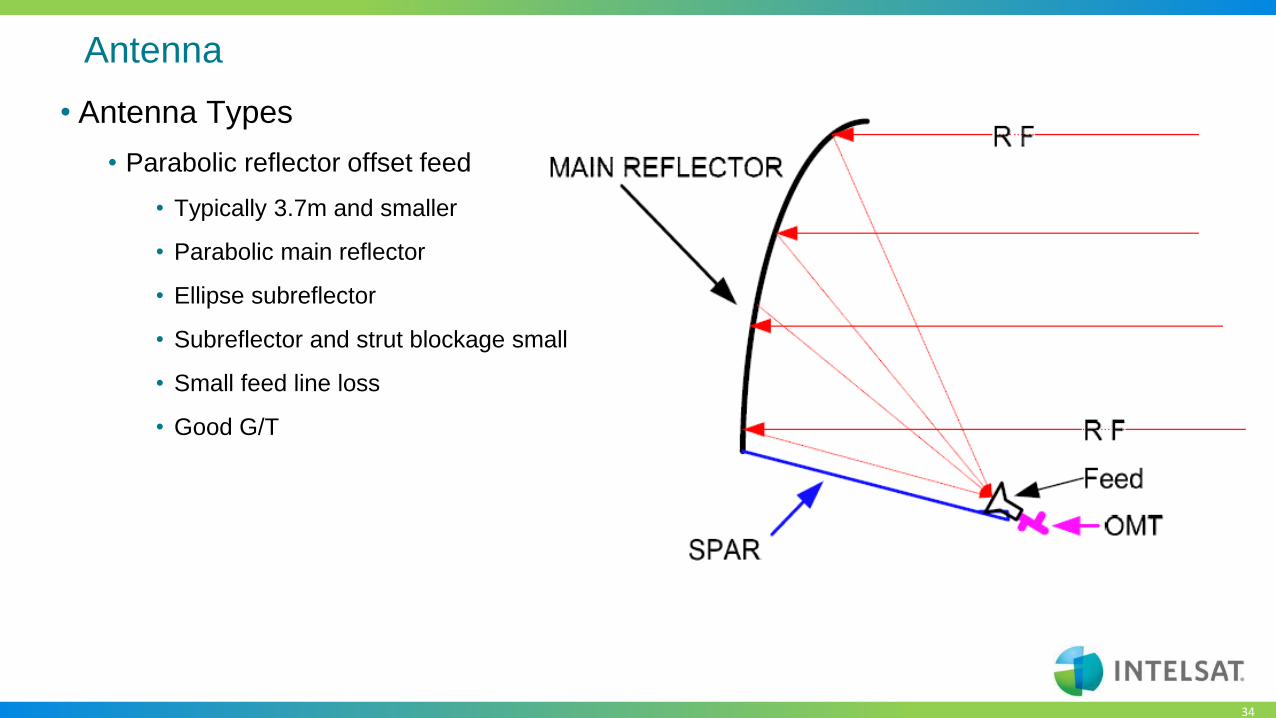
Antenna
• Antenna Types
• Parabolic reflector offset feed
• Typically 3.7m and smaller
• Parabolic main reflector
• Ellipse subreflector
• Subreflector and strut blockage small
• Small feed line loss
• Good G/T

35
Antenna
• Antenna Types
• Parabolic offset dual reflector gregorian
• Offset dual reflector system
• Main reflector parabolic
• Subreflector elliptical
• No Feed / Reflector blocking
• Small feed line losses
• Excellent C/I and cross pol purity
• Used on satellites
36
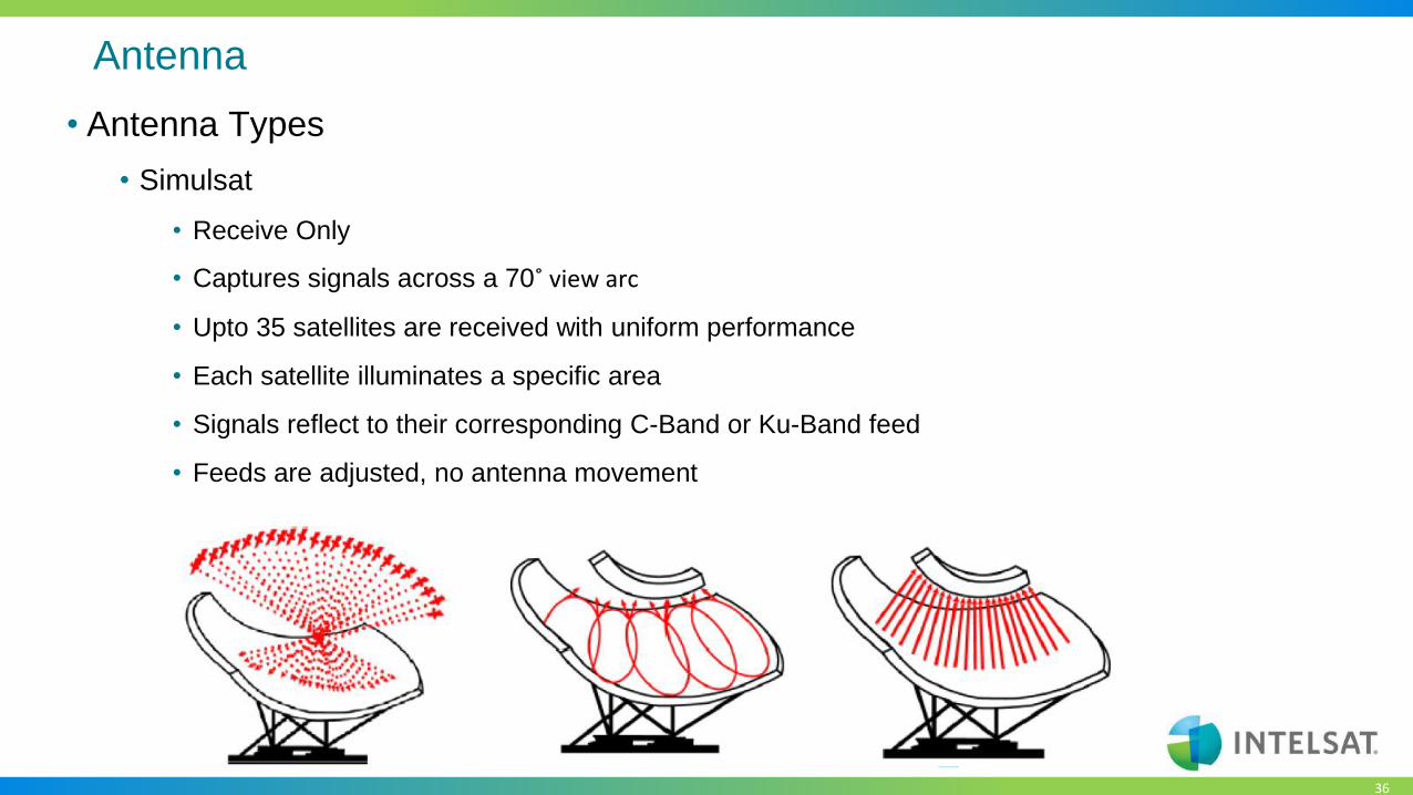
Antenna
• Antenna Types
• Simulsat
• Receive Only
• Captures signals across a 70˚ view arc
• Upto 35 satellites are received with uniform performance
• Each satellite illuminates a specific area
• Signals reflect to their corresponding C-Band or Ku-Band feed
• Feeds are adjusted, no antenna movement

37
Antenna
• Antenna Subreflector
• In a direct feed reflector, the feed horn is located at the focus or may be offset to one side of the
focus
• Large earth station antennas have a subreflector at the focus
• The subreflector permits the antenna optics to be located near the base of the antenna
• Reduces losses because the length of the waveguide between the transmitter or receiver and the antenna
feed is reduced.
• The system noise temperature is also reduced because the receiver looks at the cold sky instead of the
warm earth
• Cassegrain
• The subreflector is convex with an hyperboloidal surface
• Hyperboloidal? A mathematical surface whose sections parallel to one coordinate plane form ellipses and
those parallel to the other two coordinate planes form hyperbolas
• Gregorian
• The subreflector is concave with an ellipsoidal surface
• Ellipsoidal? A geometric surface or a solid figure shaped like an oval. Any section through an ellipsoid is
either an ellipse or a circle.

38
Antenna
• Antenna Focal Distance (f/d)
• focal distance formula: f/d = D2 / 16d
• D = Antenna Diameter
• D = depth of Parabola
f/d
D = 3.8m
d = 0.6m
f/d
D = 3.8m
d = 0.8m
f/d = D2 / 16d
D = 3.8 m
d = 0.6 m
f/d = 1.504 m
f/d = D2 / 16d
D = 3.8 m
d = 0.8 m
f/d = 1.128 m

39
Antenna
• Antenna Focal Distance (f/d)
• Shallow dish antenna
• Long focal length increases the feedhorn’s ability to illuminate the entire reflector area providing good gain
• More susceptible to:
• Earth noise at low elevation angles
• Terrestrial Interference
• Affects antenna noise temperature
• Deep dish antenna
• Short focal length decreases the feedhorn’s ability to illuminate the entire reflector area providing less gain
• Can provide advantages
• Low elevation angles
• Terrestrial interference
• Better antenna noise temperature
40
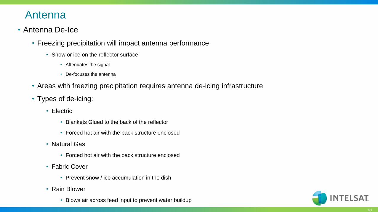
Antenna
• Antenna De-Ice
• Freezing precipitation will impact antenna performance
• Snow or ice on the reflector surface
• Attenuates the signal
• De-focuses the antenna
• Areas with freezing precipitation requires antenna de-icing infrastructure
• Types of de-icing:
• Electric
• Blankets Glued to the back of the reflector
• Forced hot air with the back structure enclosed
• Natural Gas
• Forced hot air with the back structure enclosed
• Fabric Cover
• Prevent snow / ice accumulation in the dish
• Rain Blower
• Blows air across feed input to prevent water buildup

41
Antenna
• Antenna Feed System
• 1 Port
• Receive Only
• 2 Port
• Can Receive Two signals or
• Transmit One and Receive One
• 3 Port
• One Transmit and Two Receive
• 4 Port
• Two Transmit and Two Receive
• Polarization adjustment
• Single plane: transmit and receive are fixed and both rotate
• Dual plane: transmit and receive rotate separately
42
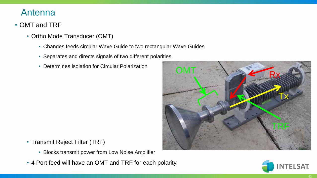
Antenna
• OMT and TRF
• Ortho Mode Transducer (OMT)
• Changes feeds circular Wave Guide to two rectangular Wave Guides
• Separates and directs signals of two different polarities
• Determines isolation for Circular Polarization
• Transmit Reject Filter (TRF)
• Blocks transmit power from Low Noise Amplifier
• 4 Port feed will have an OMT and TRF for each polarity
OMT
TRF
Tx
Rx
43
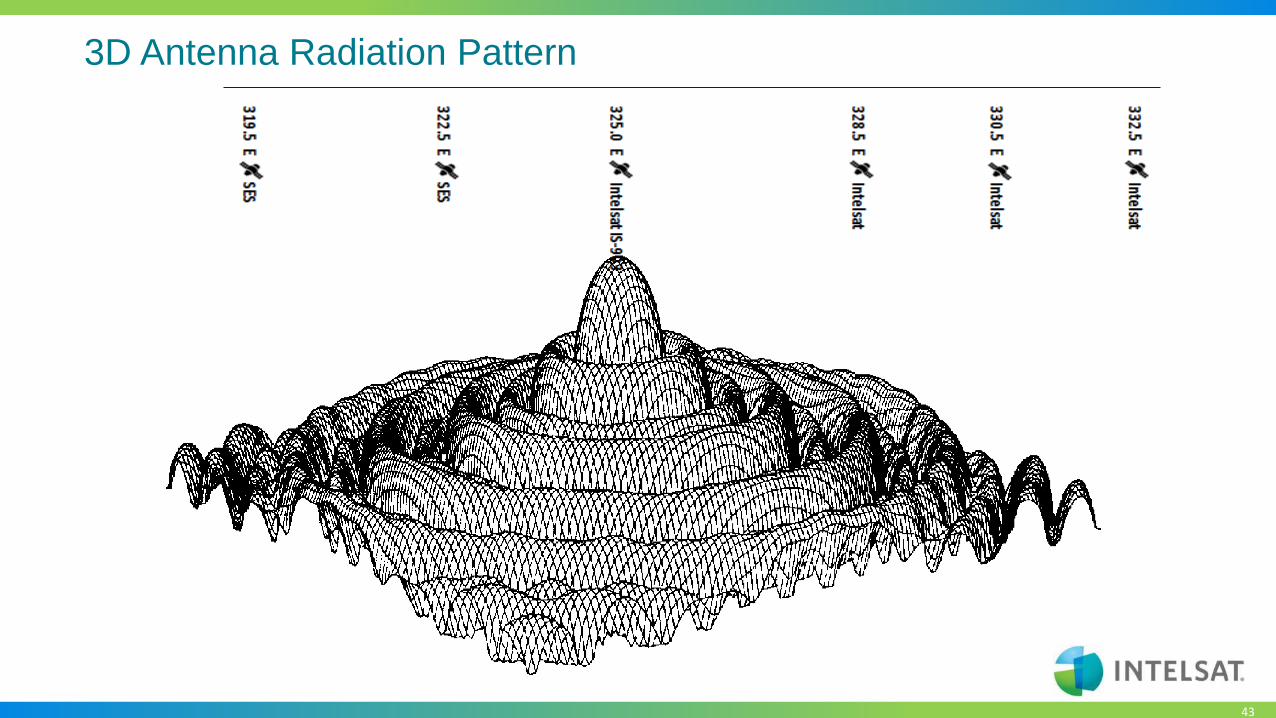
3D Antenna Radiation Pattern

44
Polarization
• Provides increased satellite capacity (Allows frequency reuse)
• The directional aspects of the electrical field of a radio signal
• Linear (90o Out of Phase)
• Horizontal (H)
• Vertical (V)
• All Ku-Band satellites are Linear
• Circular (180 o Out of Phase)
• Right Hand Circular (RHCP)
• Left Hand Circular (LHCP)

45
Linear Polarization
• Vertical
• Field lies in a plane perpendicular to
the earth’s surface.
▪ Linear Polarization
– The electrical field is wholly in one
plane containing the direction of
propagation
▪ Horizontal
– Field lies in a plane parallel to the
earth’s surface.

46
Circular Polarization
• Left Hand Circular Polarization (LHCP)
• the electric field is rotating counterclockwise as seen by an observer towards whom the wave is
moving
▪ Circular Polarization
– The electrical field radiates energy in both the horizontal and vertical planes and all planes in
between
▪ Right Hand Circular Polarization (RHCP)
– the electric field is rotating clockwise as seen by an observer towards whom the wave is moving

47
Linear Polarization
• Advantage
• Lower Cost Antenna System
• Feed Assembly (OMT)
• Better Cross-Pol Isolation
▪ Disadvantage– Polarization Adjustment Required
– Polarization changes depending on Latitude and Longitude
– Greater chance of problems due to cross-pol interference
– Faraday rotation in the ionosphere

48
Circular Polarization
•Advantage
•No polarization adjustment required
• Fixed by Ortho-Mode-Transducer (OMT)
•Less chance of cross-Pol interference
▪Disadvantage– Higher cost antenna systems
• Feed Assembly (OMT)
– Slightly lower cross-Pol isolation

49
Uplink
Modem Up-Converter Transmitter FeedIFL IFL IFL
Antenna
Simplified Uplink Block Diagram
• Uplink Block Diagram
• Modulator / Modem
• Up-Converter
• Power Amplifier
• Antenna
• Inter Facility Link (IFL)
• Fiber Optics
• Co-axial cable Combiners / Splitters
• Waveguide

50
Uplink Block Diagram
• Modulator / Modem
• Up-Converter
• Power Amplifier
• Antenna
• Inter Facility Link (IFL)
• Fiber Optics
• Co-axial cable Combiners / Splitters
• Waveguide
Modem Up-Converter Transmitter FeedIFL IFL IFL
Antenna
Simplified Uplink Block Diagram
51
Modems - Selection
• SCPC
• Low Throughput 64Kbps
• High Throughput >300Mbps
• Carrier Cancellation
• TDM/TDMA
• Simple Hubless solution
• Star Network
• Mesh network
• Advanced features
• Roll Off
52
Modem Interfaces
• RS232/RS422
• HSSI/G703/Ethernet
• D-Type connector, BNC, Ethernet
• IDR G703 E1/T1
• IBS: RS422/RS232/ITU.V35
• ASI
• Ethernet
• SDI

53
Common Modulation Techniques
• Analogue Modulation
• AM, FM, QAM, SM, SSB
• Digital Modulation
• ASK, APSK, CPM, FSK, MFSK, MSK, OOK,PPM,PSK, QAM, TCM

54
Modem – Modulation QPSK
QPSK
• One of 4 phases
• 2 bits per symbol
• 00, 10, 01, 11

55
Modem – Modulation QPSK
• When I and Q both change at the same
time then signal transitions through Zero
• Power changes abruptly
• Signal distortions

56
Modem – Modulation QPSK
• When I and Q both change at the same
time then signal transitions through Zero
• Power changes abruptly
• Signal distortions

57
Modems - Modulation
• Q – offset
• Signal never goes through Zero
• Better performance

58
Phase shift Key
• QPSK – 2 bits per symbol
• 8PSK – 3 bits per symbol
• 16APSK – 4 bits per symbol
• 32APSK – 5 bits per symbol
• etc
59
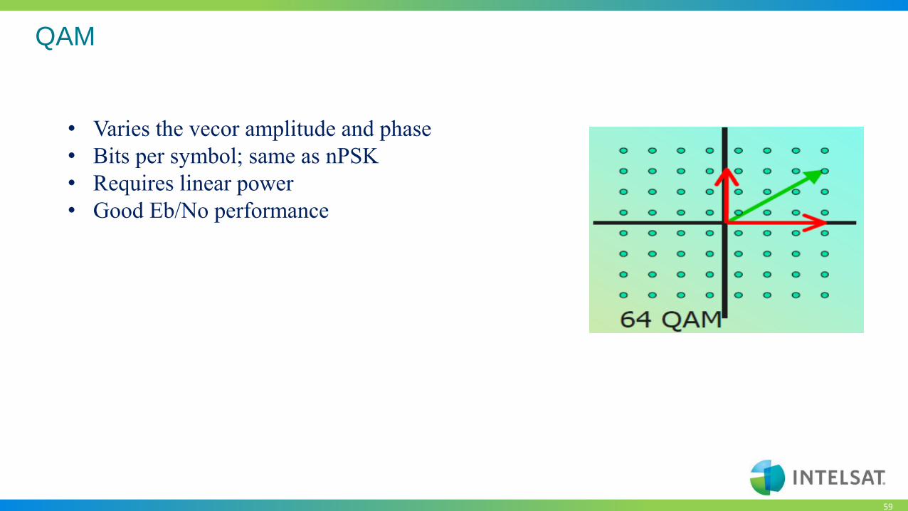
QAM
• Varies the vecor amplitude and phase
• Bits per symbol; same as nPSK
• Requires linear power
• Good Eb/No performance
60
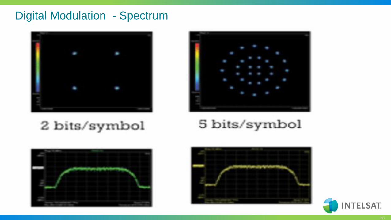
Digital Modulation - Spectrum
61
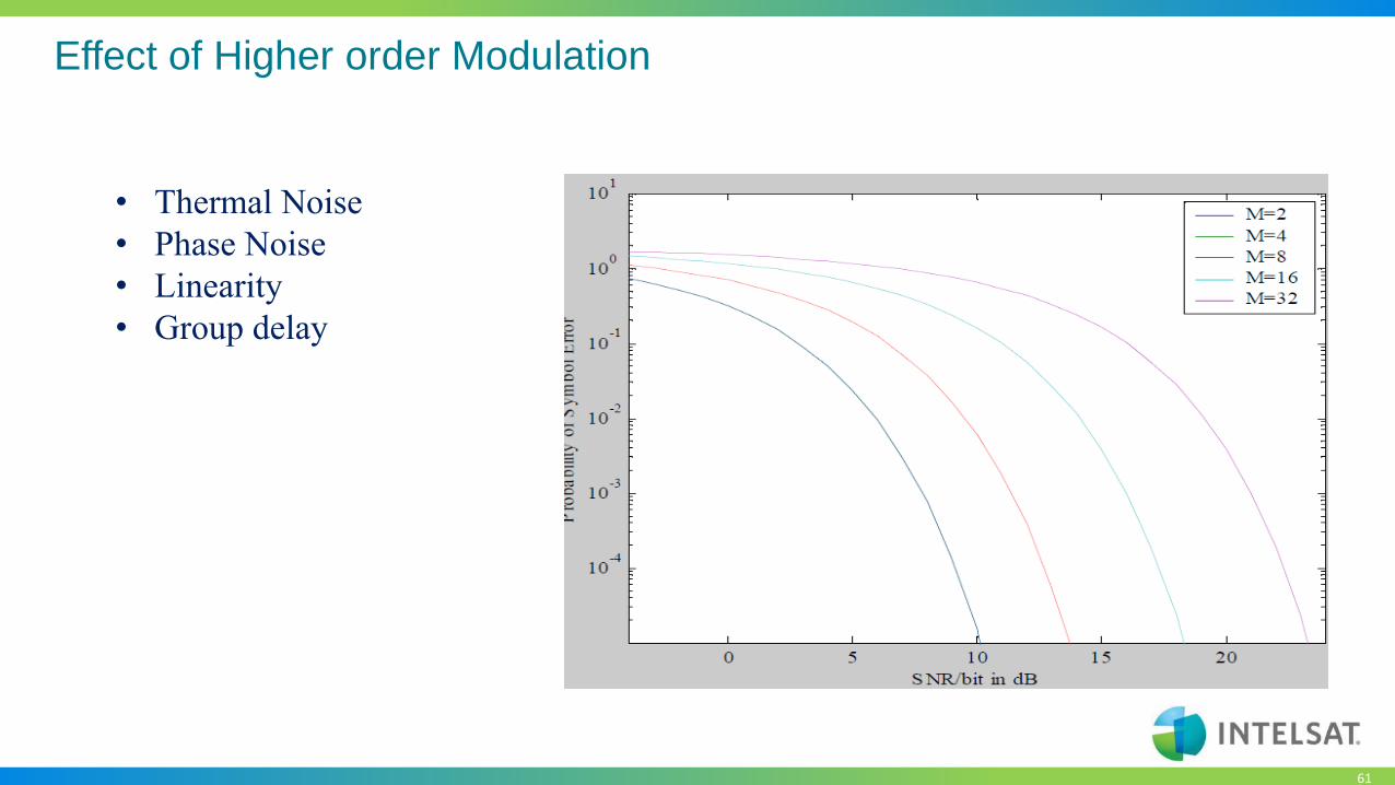
Effect of Higher order Modulation
• Thermal Noise
• Phase Noise
• Linearity
• Group delay

62
Uplink Block Diagram
• Modulator / Modem
• Up-Converter
• Power Amplifier
• Antenna
• Inter Facility Link (IFL)
• Fiber Optics
• Co-axial cableCombiners / Splitters
• Waveguide
Modem Up-Converter Transmitter FeedIFL IFL IFL
Antenna
Simplified Uplink Block Diagram

63
Up-Converter (U/C)
• The method used to achieve the conversion is heterodyning. That is the mixing of
two different frequencies into a non-linear device ( mixer ) to produce two other
frequencies equal to the sum or difference of the first two, while maintaining it’s
characteristics
• A device that converts an input signal known as the intermediate frequency (IF) to
a desired higher frequency without disturbing the intelligence (modulation) on the
incoming signal

64
Up-Converter (U/C)
• 140 MHz to L-Band
• 140 ±72 MHz input
• 950 – 1450 MHz output
• Non inverting
• 72 MHz bandwidth
• 70 / 140 MHz IF to L-Band
• 70 MHz to L-Band
• 70 ±18 MHz input
• 950 – 1450 MHz output
• Non inverting
• 36 MHz bandwidth

65
Up-Converter (U/C)
• L-Band to C-Band
• 950 - 1450 MHz input
• 5.925 – 6.425 GHz output
• Non inverting (4.900 GHz LO)
• Inverting (7.375 GHz LO)
• 500 MHz bandwidth
• L-Band to Ku-Band
• 950 - 1450 MHz input
• 14.00 – 14.50 GHz output
• Non inverting (LO = 13.050 GHz)
• Inverting (LO = 15.450 GHz)
• 500 MHz bandwidth

66
Up-Converter (U/C)
• 70 MHz to C-Band
• 70 ±18 MHz input
• 5.850 – 6.425 GHz output
• Non inverting
• 36 MHz bandwidth
• 140 MHz to C-Band
• 140 ± 36 MHz input
• 5.850 – 6.425 GHz output
• Non inverting
• 72 MHz bandwidth

67
Up-Converter (U/C)
• 70 MHz to Ku-Band
• 70 ±18 MHz input
• 14.00 – 14.50 GHz output
• Non inverting
• 36 MHz bandwidth
• 140 MHz to Ku-Band
• 140 ± 36 MHz input
• 14.00 – 14.50 GHz output
• Non inverting
• 72 MHz bandwidth

70
Uplink Block Diagram
• Modulator / Modem
• Up-Converter
• Power Amplifier
• Antenna
• Inter Facility Link (IFL)
• Fiber Optics
• Co-axial cableCombiners / Splitters
• Waveguide
Modem Up-Converter Transmitter FeedIFL IFL IFL
Antenna
Simplified Uplink Block Diagram

71
Power Amplifiers
• High Power Amplifiers - HPA
• Solid State Power Amplifiers - SSPA
• Travelling Wave Tube – TWT
• Klystron Power Amplifier KPA
• Including/excluding Up-conversion
• Transceivers

72
Transceiver
• Combination Power Supply, Up / down converter, HPA and LNA - PSU
• Mounted on / at the antenna
• 70 or 140 MHz or L-Band input
• RF Output C/Ku/Ka-Band output
• Single or dual synthesized converters
• Uplink
• DownlinkPower Supply
Up-Converter
Down-Converter
TXIF
RXIF
SSPA
LNA
Transceiver Block Diagram

75
Solid State Power Amplifiers
• Typical output power 5 to 200 Watts
• 500 MHz bandwidth
• Non Linear
• L-Band Up-Converter optional
• Requires external 10 MHz reference
• Requires Diplexer
• Typically ≈ 3 dB OBO for multi carrier operation

76
Solid State Power Amplifiers
• Lower Power 1- 200W
• Lower OBO for multicarrier operation
• Cost effective
• Low maintenance
• Power efficient
• Susceptible to power and lightning damage

79
Travelling Tube Amplifier
• Typical output power 100 – 750 Watts
• 500MHz - 750 MHz bandwidth
• Non Linear
• Built in BUC optional
• Requires 10 MHz external reference and Diplexer
• ≈ 7 dB OBO for multi carrier operation
• ≈ 4 dB OBO with linearizer for multi carrier operation

80
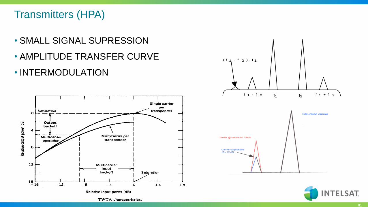
Transmitters (HPA)
• HPA HIGH POWER AMPLIFIER
• TRAVELING WAVE TUBE AMPLIFIER
• WIDEBAND ( FULL SPECTRUM ) GREATER 500MHz
• NON LINEAR
• SMALL SIGNAL SUPRESSION
• AMPLITUDE TRANSFER CURVE
81
Transmitters (HPA)
• SMALL SIGNAL SUPRESSION
• AMPLITUDE TRANSFER CURVE
• INTERMODULATION
f 1 - f 2 f 1 + f 2f1 f2
( f 1 - f 2 ) - f 1

83
Klystron Power Amplifier
• Typical output power 1000 to 3000 Watts
• Non linear
• 40 or 80 MHz bandwidth
• OBO ≈ 2 dB for dual carrier operation
• ≈ 7 dB for multi carrier operation

86
Uplink Block Diagram
• Modulator / Modem
• Up-Converter
• Power Amplifier
• Antenna
• Inter Facility Link (IFL)
• Fiber Optics
• Co-axial cable Combiners / Splitters
• Waveguide
Modem Up-Converter Transmitter FeedIFL IFL IFL
Antenna
Simplified Uplink Block Diagram

87
Inter Facility Linking
• Co-axial cabling
• Data and base band
• IF
• L-Band
• C-Band
• Ku-band

88
RF Co-axial Cabling
• Important factors
• Higher Frequency higher losses
• Losses indirectly proportional to cable diameter
• Skin effect
• To a point
• Losses directly proportional to frequency
• Reflections – impedance mismatch
• Cable damage
• Water
• System impedance
• Connector
89
Waveguide
• Used at C-Band and higher frequencies
• Lower loss than co-axial cable
• Types:
• Rigid
• Flexible, Flexible and twistable
• Elyptical
• Not wideband – Frequency determines dimension

90
Combiners Small Signal
• Types
• IF
• L-band
• C-Band/Ku-band
• Considerations
• Losses
• Impedance matching
• Terminating unused ports
91
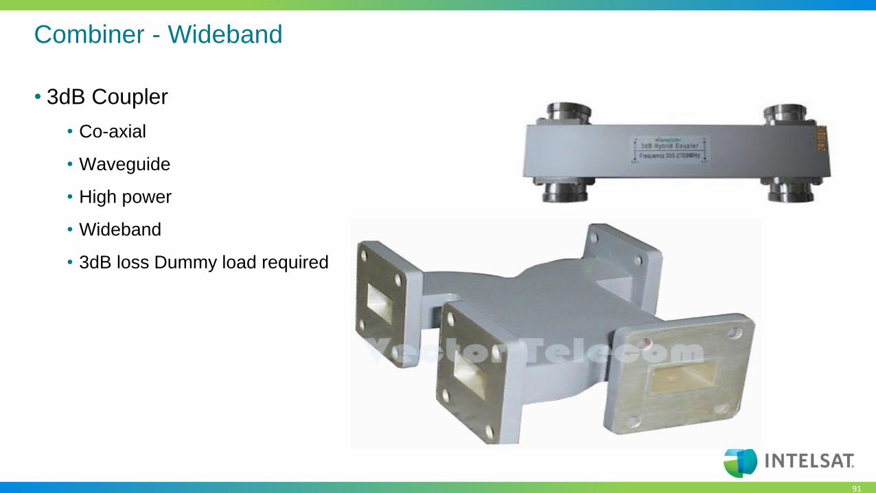
Combiner - Wideband
• 3dB Coupler
• Co-axial
• Waveguide
• High power
• Wideband
• 3dB loss Dummy load required
92
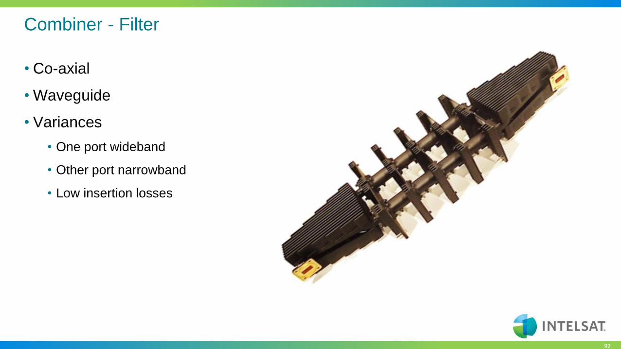
Combiner - Filter
• Co-axial
• Waveguide
• Variances
• One port wideband
• Other port narrowband
• Low insertion losses

93
Technology Trends
94
Technologies
Addressing your Bottom Line through the use of the latest technologies
• DVB-S2 Extensions
• Adaptive Coding and Modulation
• Carrier in Carrier Technology
• Lower Roll off factors
• New Technology in Satellites
• Antennas Advancements to reach new markets

95
DVB-S2 & Extensions
A new standard enables true convergence
• Excellent spectral efficiency:
• Up to 40% bandwidth saving compared to DVB-S
• Up to 2dB better than Turbo Codes
• HDTV enabler
• Unlike DVB-S, DVB-S2 is optimised for MPEG and IP
• Allows for DTH and DTT distribution in single carrier

96
DVB-S2 & Extensions

97
DVB-S2 & Extensions

98
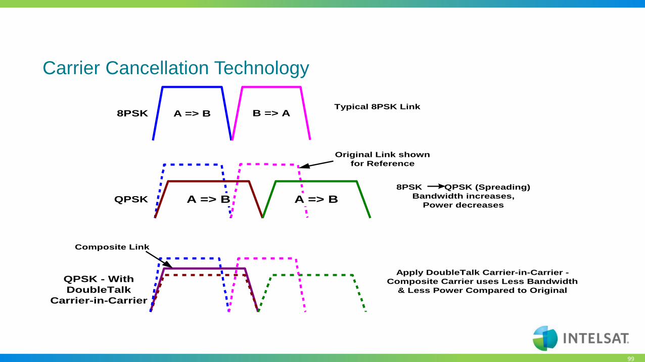
Adaptive Coding & Modulation
• Higher throughput for the same amount
of resources
• When rain fade issues arise, the
modulation can adjust so as to ensure
the remote stays in the network
• Allows lower per Mbps price points to
be achieved, leading to more
competitive prices in the market
Maximum achievable data throughput by utilizing the most efficient coding and modulation scheme at any moment in time, depending on location within the satellite contour, antenna size and atmospheric conditions
99
8PSK A => B B => ATypical 8PSK Link
QPSK
8PSK QPSK (Spreading)
Bandwidth increases,
Power decreasesA => B A => B
Original Link shown
for Reference
QPSK - With
DoubleTalk
Carrier-in-Carrier
Apply DoubleTalk Carrier-in-Carrier -
Composite Carrier uses Less Bandwidth
& Less Power Compared to Original
Composite Link
Carrier Cancellation Technology
100
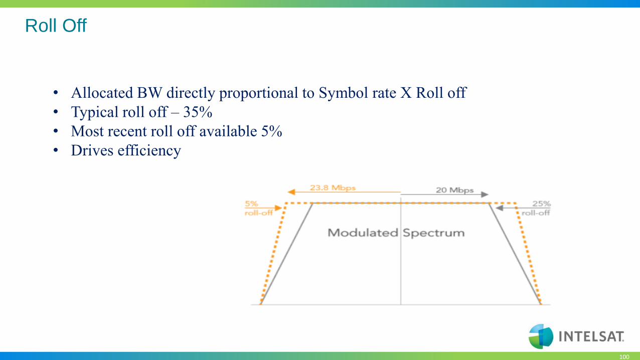
Roll Off
• Allocated BW directly proportional to Symbol rate X Roll off
• Typical roll off – 35%
• Most recent roll off available 5%
• Drives efficiency
101
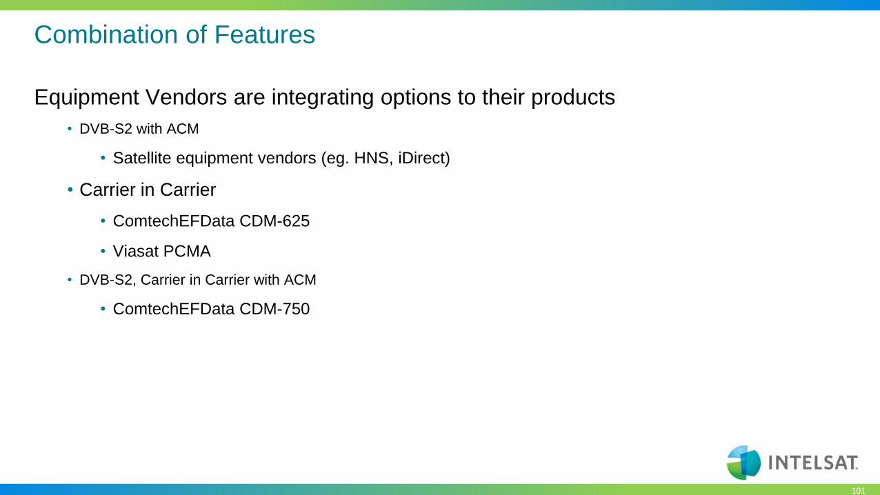
Combination of Features
Equipment Vendors are integrating options to their products
• DVB-S2 with ACM
• Satellite equipment vendors (eg. HNS, iDirect)
• Carrier in Carrier
• ComtechEFData CDM-625
• Viasat PCMA
• DVB-S2, Carrier in Carrier with ACM
• ComtechEFData CDM-750

102
New Technology in Satellites
Intelsat Satellite network evolution

103
Satellite Network Evolution
• What is a High Throughput Satellite?
• Traditional satellites currently deliver a system data throughput of 2Gbps to 5Gbps
• A High Throughput Satellite is a satellite that can deliver system data throughputs of
15Gbps or more.
• This is done by the ability of frequency reuse and a combination of Spot Beams and Wide
Beams
• Spot Beam provide the ability to concentrate power (EIRP and G/T)
• Intelsat is the first in this next advancement of satellite technology and it is
called:

104
Intelsat brings well known principles of “Frequency Reuse” & “Spot Beams” in a new
configuration
Frequency reuse(Any frequency band: C, Ku, Ka) + Spot Beams & Wide Beams
= Intelsat EpicNG
CSE

105
Frequency Reuse Methodology
1. Reduce beam size.
• This increases G/T and EIRP
2. Split frequency into 4 or 7 or 8 etc.
segments or “colors”.
3. Assign each color the segmented
bandwidth taking care not to assign any
similar colors next to each other.
500 MHz
250 MHz
250 MHz
250 MHz
250 MHz
4 Color reuse
CSE

106
IS-33e Ku-Beams
• User Beams
• Standard Ku-band frequencies (non-planned FSS)
• Bandwidth from 56.25 to 225 MHz
• Core Beams
• Use BSS and Ku-band Planned bands
• Different bands for User Beams
• Bandwidth sized to support all user beams in
corresponding country or region, for example:
• Connectivity
• Connectivity between any user and core beam

107
High Performance
High Efficiency
High Capacity
Flexible
All-region Coverage
Open Platform
Backward Compatible
Multi-band
Complementary Overlay
Lower Cost of Ownership
High Performance Satellite Platform
High Throughput
Resilient and Secure
Page: 107
108
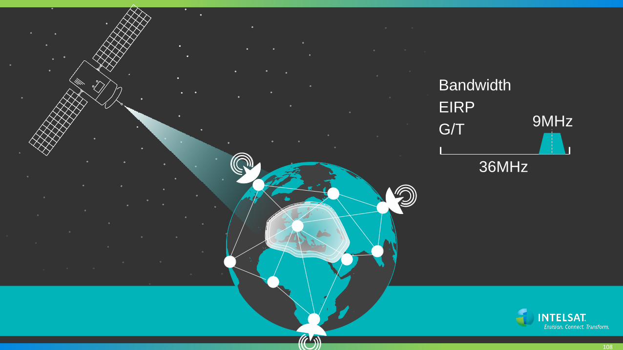
Bandwidth
36MHz
9MHzEIRP
G/T

109
This is our Existing Satellite Network…
Global coverage
25 satellites over Africa
Resilient C-band
and Ku-band transponders

110
Now Launching 7
EpicNG satellites
111
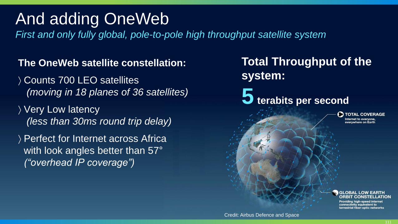
And adding OneWebFirst and only fully global, pole-to-pole high throughput satellite system
The OneWeb satellite constellation:
Counts 700 LEO satellites
(moving in 18 planes of 36 satellites)
Very Low latency
(less than 30ms round trip delay)
Perfect for Internet across Africa
with look angles better than 57°
(“overhead IP coverage”)
Credit: Airbus Defence and Space
Total Throughput of the
system:
5 terabits per second

112
Providing a Truly Global Network in the Sky
113
IS-29e
IS-33eIS-32e
IS-35eIS-35e
IS-37eH-3e H-3e
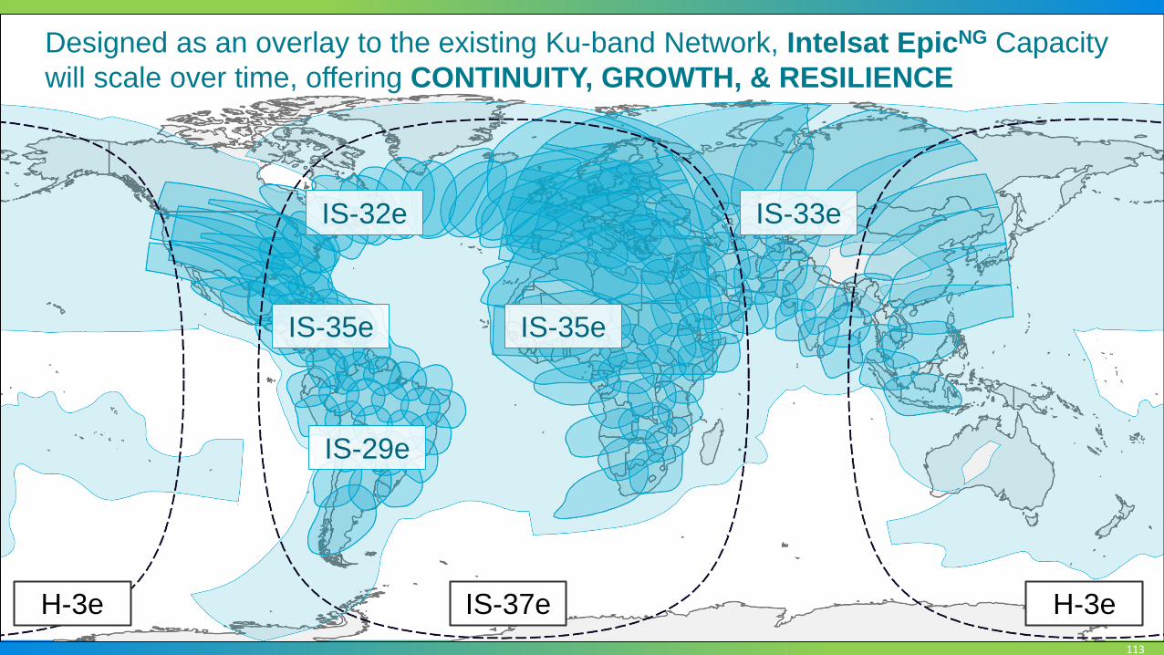
Designed as an overlay to the existing Ku-band Network, Intelsat EpicNG Capacity
will scale over time, offering CONTINUITY, GROWTH, & RESILIENCE

114
Example: Ku-band Spot Beam Network
2 MbpsRemote
150 MbpsNetwork1.8M/4W KU-BAND REMOTE
Page: 114

115
Example: Ku-band Spot Beam Network
Up to
14 MbpsReturn
EpicNG
200 MbpsNetwork throughput*
SAME 1.8m/4W remotes
SAME platform technology
PROJECTED GROWTH now
supported
ACHIEVED
GOAL
INCREASE
NETWORK
VOLUME
BOOST
RETURN
TRAFFIC
*Limited by platform technology
30THROUGHPUT INCREASE
%
7REMOTE THROUGHPUT
X
Focused EpicNG Ku-band Spot Beam
Page: 115
116
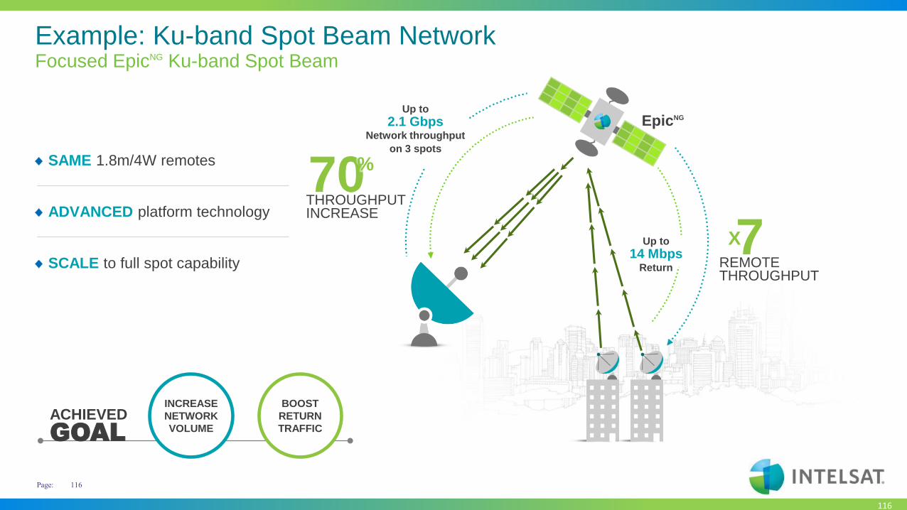
Example: Ku-band Spot Beam Network
Up to
14 MbpsReturn
EpicNGUp to
2.1 GbpsNetwork throughput
on 3 spots
SAME 1.8m/4W remotes
ADVANCED platform technology
SCALE to full spot capability
ACHIEVED
GOAL
INCREASE
NETWORK
VOLUME
BOOST
RETURN
TRAFFIC
7REMOTE THROUGHPUT
X
70THROUGHPUT INCREASE
%
Focused EpicNG Ku-band Spot Beam
Page: 116

117
Example: Ku-band Spot Beam Network
ACHIEVED
GOAL
INCREASE
NETWORK
VOLUME
BOOST
RETURN
TRAFFIC
ROLL OUT
CHEAPER
SITES
EpicNG
Up to
6 MBPSReturn
Up to
1.6 GbpsNetwork throughput
on 3 spotsNEW 1.2M/2W remotes
ADVANCED platform technology
SCALE to full spot capability
50CAPEX SAVING
%Up to
30THROUGHPUT INCREASE
%
3REMOTE THROUGHPUT
X
EpicNG Ku-band Spot Beam
Page: 117

118
Antenna Advancements

119
Redefinition of the satellite antenna
Electronically Steered Antennas (ESA)
No moving parts
Ultrathin and light
Metamaterial
Passive array Active phased array
Panels may be laid
CONFORMABLY

120

121
Flat
Lightweight
No Moving Parts
Auto-Acquiring
Self-Provisioning
Affordable

122
Mobility & Internet of Things
Form factor, affordability,
and production scalability
make mTenna technology
ideal for Mobility & IoT
Customer Benefits: IoT• Affordable terminal
• Hand-carry, self installation
• Connects to existing sensor / WiFinetworks
• Efficient, intelligent data backhaul
• Auto-acquisition and self-provisioning
• Reliability – no moving parts
• Global network with scalablethroughput
• Remote and/or mobile connectivity

123
Toyota 4Runner Equipped With mTenna Tech
© 2016. Kymeta Corporation.

124
Revolutionary, flat, electronically steerable antenna (ESA)
Thin• Very low profile, (aerodynamic, inconspicuous)
• Superior form-factor, (smaller footprint, light-weight)
Reliable• Accurate, (faster scan, better tracking, fewer network drops)
• Robust, (no-moving parts, gradual degradation vs. total system failure)
Broadband• Delivers true broadband service, (supports networks > 100Mbs)
• Very high gain (efficient, powerful)
Modular• Adaptable, (expandable to support wide requirements, lowering OpEx)
• Better logistics-tail (easier, less costly & less timely to repair )
Versatile• Broad functionality, (multi-beam, flat or conformal, distributed or contiguous)
• Dynamic control, (beam forming, tapering, ASI mitigation)
Enables mobile-broadband communications: at-sea, over land and in-flight

125125
Designed to be flat or conformal – enables Aeronautical Mobile Broadband

126
Navigation maps
Weather information
Over-the-air updates
Streaming
Sensors Analytics
Video conference
Video surveillance
127
Thank you
Questions ?