Embed Size (px)
Citation preview
ITS specification Variable message sign supply and installation – notes (ITS-06-02)
© NZ Transport Agency
First edition, Amendment 0
Effective from September 2011

Copyright information
This publication is copyright © NZ Transport Agency (NZTA). Material in it may be reproduced for personal or in-house use without formal permission or charge, provided suitable acknowledgement is made to this publication and the NZTA as the source. Requests and enquiries about the reproduction of material in this publication for any other purpose should be made to:
NZ Transport Agency Private Bag 6995 Wellington 6141
The permission to reproduce material in this publication does not extend to any material for which the copyright is identified as being held by a third party. Authorisation to reproduce material belonging to a third party must be obtained from the copyright holder(s) concerned.
Disclaimer
The NZTA has endeavoured to ensure material in this document is technically accurate and reflects legal requirements. However, the document does not override governing legislation. The NZTA does not accept liability for any consequences arising from the use of this document. If the user of this document is unsure whether the material is correct, they should refer directly to the relevant legislation and contact the NZTA.
More information …
Published September 2011
If you have further queries, call our contact centre on 0800 699 000 or write to us:
NZ Transport Agency Private Bag 6995 Wellington 6141
This document is available on the NZTA’s website at www.nzta.govt.nz.
Page i
NZ Transport Agency’s ITS specification: Variable message sign supply and installation – notes (ITS-06-02) First edition, Amendment 0
Document management plan
1) Purpose
The purpose of this document is to assist the site selection, design, environmental planning, construction of support structures, reticulation of power and communication services, and post construction acceptance and maintenance of VMS for the State Highway network where NZ Transport Agency has a responsibility to provide driver information.
2) Document information
Document name ITS specification: Variable message sign supply and installation – notes
Document number ITS-06-02
Document status Final
Document availability This document is located in electronic form on the NZ Transport Agency’s website at www.nzta.govt.nz.
Document author NZ Transport Agency Henry Pretorius [email protected] (04) 894 6492
Opus International Consultants Ltd Neil Garnett [email protected]
(03) 363 5480
Document owner Henry Pretorius [email protected]
3) Key words
VMS, Variable Message Sign, Specification, LED, Sign, Signage, Electronic, Dynamic, Safety, Advisory, Warning, CMS, ATMS, Motorway, High Volume Urban, Rural.
4) Other
This document is the NZ Transport Agency’s Notes for Variable Message Signs (VMS).
A separate document titled NZ Transport Agency Specification for Variable Message Signs is available to provide a set of specifications for the design and procurement of electronic VMS signage for motorway and regional applications.
NZ Transport Agency’s requirements for VMS messages are described in the National VMS Operating Policy and National VMS Operating Procedures.
Requirements for Mobile VMS are set out in SP/M/031 Specification for Mobile VMS, and the associated Notes.

Page ii
NZ Transport Agency’s ITS specification: Variable message sign supply and installation – notes (ITS-06-02) First edition, Amendment 0
Record of amendments
Amendment number
Section amended
Description of change Updated by Effective date

Page iii
NZ Transport Agency’s ITS specification: Variable message sign supply and installation – notes (ITS-06-02) First edition, Amendment 0
Contents
Document management plan i
Record of amendments ii
1.0 Introduction 1
1.1 Scope 1
1.2 Definitions and acronyms 1
2.0 Process, hold points and responsibilities 4
2.1 Process 4
2.2 Hold points and responsibilities 4
3.0 VMS site selection 5
3.1 VMS site selection criteria 5
3.1.1 Strategic locations – an introduction 5
3.1.2 Minimum distance from key intersections 5
3.1.3 Influence of message suite on sign configuration 5
3.1.4 Speed environment and character height 6
3.1.5 Standard sign types for regional VMS 6
3.1.6 Clear sight distance 6
3.1.7 Road angle vertical plane 6
3.1.8 Road angle horizontal plane 7
3.1.9 Road geometry 8
3.1.10 Presence of other signage 8
3.1.11 Space to ensure safety conformance 8
3.1.12 Width and boundary of road reserve 8
3.1.13 Site access 8
3.1.14 Access to mains power 9
3.1.15 Communications coverage 9
3.1.16 Extreme weather or other environmental conditions 9
3.1.17 Foundation conditions 9
3.1.18 Safety issues - above and below ground services 9
3.1.19 Environmental impact and public consultation 10
4.0 Road safety requirements 11
4.1 Overview 11
Page iv
NZ Transport Agency’s ITS specification: Variable message sign supply and installation – notes (ITS-06-02) First edition, Amendment 0
4.1.1 Motorway 11
4.1.2 HVU and rural 11
4.2 Barrier protection 11
5.0 Urban design, environmental planning, site services, and land issues 12
5.1 Urban design requirements 12
5.2 Environmental planning 12
5.2.1 Outline plan 12
5.2.2 Resource consents 13
5.2.3 Assessments of environmental effects 13
5.3 Arranging power supply and network connection 14
5.3.1 Mains power 14
5.3.2 Network connection and supplier agreement 14
5.4 Communication services 15
5.5 Land issues 15
6.0 Choosing the appropriate character height 16
6.1 Considerations for regional VMS 16
6.2 Character height for regional VMS 16
7.0 Communications 17
8.0 Civil design requirements 18
8.1 Support structure options 18
8.2 Prescribed design routes 19
8.3 Standard solutions for regional VMS 20
8.3.1 Foundation conditions for regional VMS 20
8.3.2 Face area of VMS sign panel 20
8.3.3 Sign mounting height 20
8.3.4 Site design wind speed 21
8.3.5 Structure importance level (AS/NZS 1170.0) 21
8.3.6 Frangible structures 21
8.4 Specific engineering design 22
8.4.1 General 22
8.4.2 Access ladder and platform for motorway VMS 22
8.4.3 Applicable design standards 22
8.4.4 Foundation design 23
8.4.5 Design loadings 23

Page v
NZ Transport Agency’s ITS specification: Variable message sign supply and installation – notes (ITS-06-02) First edition, Amendment 0
8.4.6 Design wind speed 24
8.4.7 Structure serviceability requirements 24
8.4.8 Low temperature performance 24
8.4.9 Durability requirements 24
8.5 Building consent requirements 24
9.0 Support structure construction 25
9.1 Site set-out 25
9.1.1 Motorway VMS 25
9.1.2 Regional VMS 27
9.2 Unforeseen foundation conditions for regional VMS 29
9.3 Construction verification 29
9.4 Traffic management 29
10.0 Post-commissioning documentation 30
10.1 As-built drawings 30
10.2 Operating servicing and maintenance manuals 30
11.0 VMS structures inspection and maintenance 31
11.1 Inspection 31
11.2 Maintenance 31
12.0 Appendices 32
12.1 Appendix 1 – Site assessment proforma for regional VMS 33
12.2 Appendix 2 – Site acceptance test proforma (civil works) 34


Page 1
NZ Transport Agency’s ITS specification: Variable message sign supply and installation – notes (ITS-06-02) First edition, Amendment 0
1.0 Introduction
1.1 Scope
These notes provide guidance to the specification for variable message signs (VMS). They should be read in conjunction with the specification.
Accordingly the scope of this document has been defined as follows:
1. Site selection.
2. Design of support structures.
3. Road safety.
4. Urban design and environmental planning.
5. Construction of support structures.
6. Power and communication services.
7. Post construction acceptance and maintenance.
These notes cover:
• motorway VMS
• regional VMS which encompass:
– High volume urban (HVU) VMS
– rural VMS.
1.2 Definitions and acronyms
Term/Acronym Definition
ADSL Asynchronous Digital Subscriber Line.
Angle of Internal Friction Soil shear strength. Generated by-inter particular contact.
ATMS Advanced Traffic Management System.
Barrier Protection Generic term covering various roadside protective barrier systems including rails, fences, and crash cushions, which are designed to restrain vehicles which are out of control.
Bezel The border surrounding the VMS enclosure, mounted flush with the polycarbonate front panel.
cd Candela.
CDMA Code Division Multiple Access. The term refers to a cellular telecommunication network.
CIS Customer Information Services (NZTA).
Clear Zone The area adjacent to the road that is clear of fixed or non-frangible objects and provides a recovery zone for vehicles that have left the carriageway.
CMS Changeable Message Sign.
Cohesion (C) Soil shear strength. Generated by inter-particular forces.
CoPTTM The NZ Transport Agency’s Code of practice for temporary traffic management.

Page 2
NZ Transport Agency’s ITS specification: Variable message sign supply and installation – notes (ITS-06-02) First edition, Amendment 0
Term/Acronym Definition
Design Wind Speed Ultimate wind speed at the site based on terrain and return period.
DHCP Delivered IP Dynamic Host Configuration Protocol - it allows devices to configure their own network settings by querying a host server about the details of the network.
Enclosure The enclosure housing the display and the electronics systems immediately associated with the display.
Ethernet Protocol Industry standard network Broadcast technology.
FAT Factory Acceptance Test (Also see SAT).
FDCU Field Device Control Unit.
Frangible Performance capability of structures, which are designed to shear or collapse when struck by a vehicle, minimising the impact hazard to the vehicle’s occupants.
Gantry In the context of this document, a support structure with legs on each side of a carriageway, designed to support an overhead sign.
GDM The NZ Transport Agency’s State highway geometric design manual.
GPRS General Packet Radio Service.
GSM Global System for Mobile communication
High Voltage Lines Lines carrying electrical current greater than: 1000 volts AC or 1500 volts DC.
HVU High Volume Urban. In the context of this document HVU refers to non-motorway, generally high volume roads, in urban environments.
ITS Intelligent Transport Systems.
Lantern In the context of this document, a lantern consists of multiple LEDs in a circular grouped array.
LCD Liquid Crystal Display.
LED Light Emitting Diode.
LODMAT Lowest Observed Daily Mean Air Temperature. Used when considering design parameters for materials in low temperature environments.
Low Voltage Lines Lines carrying electrical current less than: 1000 volts AC or 1500 volts DC.
M23 NZTA specification for Road Safety Barrier Systems.
MACA Monitoring And Control Application. The NZTA’s software that monitors and controls VMS message changing.
MIB Message Information Block
Motorway Roads designated as motorways, generally characterised by high volume multilane carriageways.
MOTSAM The NZ Transport Agency’s Manual of traffic signs and markings and its progressive replacement, the Traffic control devices manual (TCDM).
NCHRP 350 National Highway Cooperative Research Programme report. Recommended Procedures for the Safety Performance Evaluation of Highway Features.
NTCIP National Transportation Communications for ITS Protocol.
NZTA NZ Transport Agency
P/24 The NZTA’s Performance based specification for traffic signs which covers performance of frangible structures.

Page 3
NZ Transport Agency’s ITS specification: Variable message sign supply and installation – notes (ITS-06-02) First edition, Amendment 0
Term/Acronym Definition
Pixel A single point in a graphic image. In the context of this document pixels must achieve the viewing angle, luminance, and other performance characteristics described in this Specification.
The performance characteristics may be achieved with a pixel consisting of a single LED, or closely grouped LEDs, that present a single point of light at a normal viewing distance.
RCA Road Controlling Authorit.
Regional VMS In the context of this document regional VMS refers to non-motorway VMS. Regional VMS are not as large and are generally mounted on roadside structures as opposed to overhead gantries.
RHS Rectangular Hollow Section. Used in this document in context of support structure materials.
Road Reserve A corridor of land owned by the crown, which is designated for roading infrastructure.
RS-232/485 Is a standard for serial connections.
Rural In the context of this document Rural refers to low average volume uncongested roadways in non-urban environments.
Scala Penetrometer Test equipment used to determine the penetration resistance of soil.
SAT Site Acceptance Test (Also see FAT).
Slip Base A shearing system for support structures involving upper and lower base plates clamped together by slip bolts in slots that are tightened to a prescribed torque.
SNMP Simple Network Management Protocol.
Soil Density The mass of particles in the material divided by the volume.
Strength Reduction Factor (Φ) A factor used to multiply the nominal capacity to obtain the design capacity.
Support Structures Structures supporting VMS.
TCDM The NZ Transport Agency’s Traffic control devices manual.
Terrain Category Multiplier applied to the wind speed to reflect the topography around the site.
TTM Temporary Traffic Management.
UB Universal Beam. Used in this document in context of support structure materials.
UMTS Universal Mobile Telecommunications System.
UPS Uninterruptible Power Supply.
VMS Variable Message Sign.
WEL The white edge line painted on a road.

Page 4
NZ Transport Agency’s ITS specification: Variable message sign supply and installation – notes (ITS-06-02) First edition, Amendment 0
2.0 Process, hold points and responsibilities
2.1 Process
The process starts by defining objectives and requirements for a proposed VMS installation. These include:
• Strategic network linkages and requirements
• Route(s) covered
• Potential scenarios which in turn produce a suite of messages
• Characteristics of the intended message recipient spectrum
• Criticality of such factors as response time and system reliability
• Operation and control of the VMS.
2.2 Hold points and responsibilities
Table 1: Hold points and responsibilities
Description Phase Responsibility
1 Define objectives for proposed VMS. Concept NZTA Regional Office
2 Complete site investigations and determine sign types, concurrent with Item 3 selection of communication and control systems.
Concept NZTA Regional Office
3 Determine appropriate communication and control systems in conjunction with Item 2. Concept NZTA National Office
4 Assess concept. Ensure it meets the NZTA’s criteria, is technically sound and will add value. Concept NZTA Regional Office
5 Capital funding application. Concept NZTA Regional Office
6 Funding approval based on national objectives, route priorities, and funding availability. Concept NZTA National Office
7 Confirm all requirements including land, access, communication, power, and environmental planning, are resolved or imminently resolvable.
Concept NZTA Regional Office
8 Motorway VMS:
Conclude tendering process for procurement of integrated package of support structure, civils and display.
Tender Process
NZTA Regional Office, with t National Office
Regional VMS:
Conclude tendering process for national procurement of display units.
Conclude procurement process for regional support structures and civil works.
Tender Process
NZTA National Office
NZTA Regional Office
9 For regional VMS, manage interface between VMS enclosures, and civil/supports. Design NZTA National Office
10 Approval of support structure/foundation design if non-standard. Design NZTA Regional Office
11 Confirm site layout, and construct support structure. Construction NZTA Regional Office
12 Site Acceptance Test (SAT) of civil works. Construction NZTA Regional Office
13 Factory Acceptance Test (FAT) of display enclosure. Construction NZTA National Office
14 Site Acceptance Test (SAT) of the VMS. Commission NZTA National Office
15 Ongoing asset management, including support, maintenance, and communication Operational NZTA Regional Office (NZTA National Office)

Page 5
NZ Transport Agency’s ITS specification: Variable message sign supply and installation – notes (ITS-06-02) First edition, Amendment 0
3.0 VMS site selection
3.1 VMS site selection criteria
VMS site selection must take into account a large number of inter-related factors. There is a close relationship between site selection and selection of the sign size/display technology. Site considerations influence the selection of sign and technology, and sign constraints influence the choice of site.
The strategic location and anticipated simultaneous message suite determine the number of characters per line and lines for each sign. The character height is subsequently decided during site selection based on the speed environment and other factors at the proposed site.
3.1.1 Strategic locations – an introduction
VMS projects are generally justified on the benefits of establishing a sign or signs at strategic locations or nodes on the state highway network. At a macro level the site selection process must identify all potentially suitable sections of highway for sitting VMS to ensure that viable options are not excluded from subsequent consideration.
The network video, which provides a “motorist’s eye view” of the state highway system, is an extremely useful tool to rapidly and safely identify potential sites before actual site visits are undertaken.
The VMS must be positioned above or to the left of the approaching motorist. In virtually all situations it is considered unsafe to position a VMS on the right hand side of approaching traffic because it may confuse motorists’ point of reference under night time conditions and lead to a head on collision.
3.1.2 Minimum distance from key intersections
If the VMS is intended to advise route diversions, the sign should be located sufficiently in advance of the alternate route intersection to allow motorists to assimilate the message and respond accordingly, including changing lanes if necessary.
Motorway VMS should be placed a minimum distance of 1,500 metres prior to an access/diversion point. This distance provides the motorist with roughly 50 - 60 seconds from the time they have read the message until they reach the access/diversion point.
On high volume urban (HVU) roads, the distance is dependent on considerations such as the speed limit, local factors, and right-of-way constraints.
On a rural single lane roadway, with no need to change lanes, but acknowledging the complexity of some decisions and the route choices, a distance equating to at least 1,000 metres in a 100 km/h zone, or a proportionally reduced distance in lower speed zones, is suggested.
If a rural VMS with low traffic volumes (e.g. 2,000 AADT) may display a message advising motorists to turn back, consideration should be given to choosing a site that has a suitable pull over / turning area just after the sign for travellers to turn around.
With higher traffic volumes in a high-speed environment, a level (~10,000 AADT) is reached where pulling over or turning around is unsafe. Professional judgement should be exercised as to whether pull over/turning areas are appropriate.
3.1.3 Influence of message suite on sign configuration
The number of locations or routes covered by the sign, and range of messages required to be displayed at any one time, influence the selection of sign. This is particularly true in the rural context where a choice is made

Page 6
NZ Transport Agency’s ITS specification: Variable message sign supply and installation – notes (ITS-06-02) First edition, Amendment 0
between two or four line signs. The interaction between this aspect, speed environment, and character height must reach a mutually compatible solution. Character height in turn determines sign width. It is therefore necessary to establish the maximum likely range of messages to be displayed at any one time, and understand sign type options before undertaking detailed site selection. Refer to section 6 Choosing the appropriate character height.
3.1.4 Speed environment and character height
Refer to section 6 Choosing the appropriate character height. The minimum character heights are based on Table 1 of the UK Design manual TD 33/05.
The standard categories of character height for the NZTA’s VMS are:
• 400mm for motorway
• 300mm and 200mm for HVU and rural, dependent on message size and speed environment.
The character height determines the width of regional signs, and hence influences site selection i.e:
• Standard regional VMS with 300mm character height is ~ 5 metres overall width.
• Standard regional VMS with 200mm character height is ~ 3.3 metres overall width.
3.1.5 Standard sign types for regional VMS
The sign types are summarised in the table below.
Table 2: Standard regional sign types (A, B, C, D and F)
Character Height mm Number of Lines
Type A 300 4
Type B 300 2
Type C 200 4
Type D 200 2
* Type F 160 2
* Type F is only recommended for slow speed sites with tight space constraints.
3.1.6 Clear sight distance
In motorway and HVU settings there are typically many other signs and distractions that compete for motorists’ attention. Visibility and impact, proportional to the environmental context, are particularly important considerations of site selection.
For rural VMS the designer should look for sites that allow motorists clear sight distance to the sign of at least 375 metres for 300mm character height, and at least 250 metres for 200mm character height, when travelling 100 km/h. In lower speed environments the distances can be reduced proportionally.
Ensure that road side trees or other structures will not obscure the sign. Ensure that requirements for trimming or other activities to maintain clear line of sight in the foreseeable future can be legally enforced.
3.1.7 Road angle vertical plane
The designer must take into account the viewing angle of the LEDs when considering a site. The total width of the standard LED viewing angle or illumination cone for motorway VMS is 14 degrees, while for HVU and

Page 7
NZ Transport Agency’s ITS specification: Variable message sign supply and installation – notes (ITS-06-02) First edition, Amendment 0
regional VMS it is 30 degrees. Note however that VMS with shade louvers may have a reduced viewing angle in the vertical plane.
Correct alignment is important to ensure approaching motorists will remain within the cone of illumination for as long as possible. The ability to optimally align the VMS in the vertical plane must be considered when the approach is up a steep hill, or if the VMS is unusually high above the road.
3.1.8 Road angle horizontal plane
If possible avoid positioning the VMS directly in front of a rising or setting sun as this may significantly reduce its effective visibility. Similarly, reflections of the sun on the display face may reduce its legibility even with louvers or an anti-glare mask. Note the seasonal variation between the intersection of the arcs of the (higher) summer sun and the (lower) winter sun, and the horizon.
Where these display visibility factors cannot be mitigated by e.g. taking advantage of a natural backdrop of a hill or trees, or a downhill slope, then the use of a hood or louvers should be considered to shield the display.
In certain situations e.g. where traffic is angling across, rather than directly approaching the sign, it may be necessary to specify LEDs with a wider non-standard illumination cone.
Figure 1: Illustration of illumination cone for roadside regional VMS on straight road
The right side of the cone should be aligned along the road reserve
parallel with the road
The LED cone is shown in orange.
View from behind and above the VMS.

Page 8
NZ Transport Agency’s ITS specification: Variable message sign supply and installation – notes (ITS-06-02) First edition, Amendment 0
3.1.9 Road geometry
Avoid positioning a VMS immediately before a sharp bend, blind crest, or intersection, where the VMS may distract attention at a critical moment and could lead to loss of driver control.
Also the VMS must not be positioned where the display may be seen from a neighbouring road if this will result in motorists receiving confusing or conflicting information.
3.1.10 Presence of other signage
VMS should not compete with other existing signs and or strong light emitting sources or interfere with traffic control devices. The designer must make an inventory of all signs and traffic control devices both proceeding and beyond the potential site. Based on this inventory, existing signs may need to be moved to accommodate the VMS placement.
MOTSAM requires different signs to be located a minimum of (0.6V85) apart, where V85 is the 85th percentile speed of traffic, in km/h, at the sign location.
3.1.11 Space to ensure safety conformance
In the motorway context, gantry support structures will normally require barrier protection.
For regional VMS the width of the left hand road reserve is a crucial determinant in the decision process. The space must accommodate the width of the proposed sign, space for barrier protection if required, and allow a further distance to the edge of the live lane dependent on speed environment (refer to the table in section 4 Road safety requirements).
Regional VMS support structures should be sited outside the clear zone where practicable. Consideration should be given to natural protection afforded by positioning signs on top of cuttings or beyond culverts, providing the other site selection requirements can be met.
For speed environments at or above 70 km/h, structures in the clear zone must be frangible or protected.
Below 70 km/h there is no requirement to protect non-frangible signs, but the supports should be located as far from the road edge as practicable. Where a barrier is possible this should be considered especially when pedestrians and cyclists are using roadway or footpath.
Full matrix signs are now standard for all NZTA applications where flexibility to support text heights greater than the standard line height and/or graphics in the future is required.
Refer to section 4 Road safety requirements. This section covers space requirements for barrier protection, and also the conditions where a frangible support may be used.
3.1.12 Width and boundary of road reserve
Having established the space requirements for the VMS and any barrier protection, it is essential to identify the position of the legal boundary in relation to the boundary fence or other indication of the edge of the road reserve. The position of the boundary fence and the legal boundary of the road reserve may not coincide. It may be sufficient to overlay boundary plans on an aerial photo, or a survey may be required to establish the legal boundary.
3.1.13 Site access
The site must allow reasonable vehicle access for erection, and for reactive and routine maintenance. The design should allow:
• Safe access to the sign for maintenance vehicles

Page 9
NZ Transport Agency’s ITS specification: Variable message sign supply and installation – notes (ITS-06-02) First edition, Amendment 0
• Minimise the exposure to hazards posed between maintenance vehicles and personnel, and traffic in the live lane(s)
• Facilitate effective traffic control for any maintenance work above the carriageway.
3.1.14 Access to mains power
Assuming the VMS will be mains powered, it is necessary to estimate the cost of supplying power to the site. If there is not an existing power supply nearby, or if a line must be run over private property, the cost and delay factors can be significant.
If the power supply must come from the other side of the roadway, trenching across the State Highway is not acceptable, an aerial cable may also not be acceptable, and thrust boring may be the only option.
3.1.15 Communications coverage
The communication options to the signs must be decided in conjunction with the NZTA’s National Office Network Operations – Customer Information Services Manager. Refer to section 7 Communications.
Depending on the communication options being considered, it may be necessary to establish the location of the nearest suitable hardwiring, or the strength of the cellular coverage at the proposed sites.
The installation (capital) cost, operating cost, and fitness for purpose of the communications options must be established.
3.1.16 Extreme weather or other environmental conditions
Avoid sites prone to flooding where possible. If necessary use a tall traffic signal type roadside cabinet ensuring its position does not offer vandals a platform to reach the VMS. Consideration must be given to extreme or unusual conditions at each site that will require upgrading of part of the design. Extreme winds that are more likely >500m altitude, on a ridge or cutting, or in a lee effect multiplier zone, affecting foundations and structural support design; and corrosive environments requiring enhanced coating systems are obvious examples. Other less obvious examples are the need to protect exposed equipment in alpine locations from wildlife.
3.1.17 Foundation conditions
The foundations for large motorway, single pole, cantilevered, and other VMS structures outside the standard rural type designs; require a detailed geotechnical assessment of the ground conditions, the specifics of which are not covered in these Notes. However copies of VMS as-builts used as part of Auckland and Wellington projects are available from respective offices.
The regional VMS two-post support structure standard designs, and the single post centre mounted support structure standard designs, include foundation designs for a specified envelope of wind and ground conditions. To reduce the risk to the NZTA from the contractor encountering unforeseen ground conditions, the designer shall carry out appropriate investigations before a site is recommended. Refer to section 8.4.4 Foundation design and section 8.3.1 Foundation conditions for regional VMS. The results of these investigations shall be used to determine whether the standard designs may be adopted. If ground conditions are poorer than the specified criteria at any site, then either an alternative foundation design must be provided in the tender, or sufficient information must be included to enable tenderers to submit foundation designs for approval.
3.1.18 Safety issues - above and below ground services
The top of the sign shall not be located any closer than 2 metres to overhead low voltage power lines, and not closer than 4.5 metres for high voltage lines. However some power companies may require slightly greater separation distances.

Page 10
NZ Transport Agency’s ITS specification: Variable message sign supply and installation – notes (ITS-06-02) First edition, Amendment 0
Note should be made if the site is under power lines low enough to interfere with erection of the support structure and this information should appear in the tender documents.
Note - A check must also be made for the presence of underground services before digging, or testing with a scala penetrometer.
3.1.19 Environmental impact and public consultation
Potential costs and delays arising from environmental planning and consent requirements must be considered when assessing a site, as a large VMS and its support structure may be visually intrusive on the surrounding area.
As a minimum requirement there is a need to consider the need to consult with nearby residents particularly those within the LED illumination cone, as the light emitted at night may create adverse effects.
Professional judgment must be exercised as to the likely requirement for a consultation process, and the range of likely risk to the project in terms of community sustainability, time and cost. Depending on the outcomes of these considerations, alternative sites may need to be considered.
Refer to section 5.2 Environmental planning.

Page 11
NZ Transport Agency’s ITS specification: Variable message sign supply and installation – notes (ITS-06-02) First edition, Amendment 0
4.0 Road safety requirements
4.1 Overview
4.1.1 Motorway
In the motorway context, gantry support structures will normally require barrier protection.
4.1.2 HVU and rural
In the HVU and rural context, support structures should be sited outside the clear zone where practicable. Consideration should be given to natural protection afforded by positioning signs on top of cuttings or beyond culverts, providing the other site selection requirements can be met.
For speed environments at or above 70 km/h, structures in the clear zone must be either frangible, or protected to NCHRP 350 Test Level 3.
Where a barrier is being considered the needs of pedestrians and cyclists need to be taken into account.
For speeds below 70km/h structures in the clear zone where practicable, shall meet NCHRP 350 Test Level 2 impact performance. The supports should be located as far from the road edge as practicable.
4.2 Barrier protection
Where barriers must be installed to protect a sign, the NZTA (Utility Structures in SH Corridors 22 December 2005) has proposed the following minimum distances:
Table 3: Typical barrier offset
Typical barrier offset from edge line
Design speed (km/h) Offset (m)
80 2.0
90 2.2
100 2.4
A further minimum distance of 1.0 metre should be allowed between the VMS support structure and the barrier.
Where safety barriers or guardrails are provided to protect the VMS support structure and any associated equipment, the design shall comply with the NZTA’s State highway geometric design manual (or its successor) and the NZTA’s M23 (Specification for Road Safety Barrier Systems).

Page 12
NZ Transport Agency’s ITS specification: Variable message sign supply and installation – notes (ITS-06-02) First edition, Amendment 0
5.0 Urban design, environmental planning, site services, and land issues
5.1 Urban design requirements
As a signatory to the New Zealand Urban Design Protocol, the NZTA has a role to ensure that VMS respond to and enhance the environment in which they are placed.
VMS can potentially add to the visual clutter on the roadside. It is important that VMS are located in relation to other elements in the visual field of view and that the design of support elements are not neglected and unrelated to other roadscape elements.
Whilst the design of the VMS is constrained due to safety reasons etc, their size, placement, support structures and related elements, including rear surfaces, can often be modified to improve the visual quality of roads and surrounding areas without compromising the signs purpose or road users safety.
Key strategies and actions for VMS include:
• Design VMS as a vital element of the visual experience of the road and a possible means of reducing the number of signs.
• Ensure coordination and possible co-location of VMS with other roadscape elements.
• Ensure that the local character of an area is not adversely impacted by unnecessarily large and poorly located VMS.
• Design support structures and related signage hardware to be integrated with other elements such as lighting, bridge and guard rails, emergency phones, advertising etc.
• Where VMS are to be located on overbridges, integrate them into the design of these structures if possible so that they do not appear as “add-ons”.
• Explore ways to improve the appearance of the rear of the VMS.
5.2 Environmental planning
5.2.1 Outline plan
Where VMS are to be located within the boundary of a road designation, the territorial authority (City or District Council) may require an Outline Plan for the works. It is recommended that discussions be held with the appropriate territorial authority early in the project to determine their requirements.
Where a road designation is in place, resource consent will not be required to install a VMS. Works in accordance with the designation will override the District Plan rules. An exception to this would be if there were conditions on the roading designation relevant to the VMS such as sign height, sign area, letter size, or illumination. If a VMS exceeded the relevant conditions, resource consent would be required (refer to sections 5.2.2 and 5.2.3 below). However, conditions on roading designations relating to signage are uncommon and many District Plans provide for traffic management signs on roads as permitted activities. A check should be made as to whether the sign would be a permitted activity.
Section 176A of the Resource Management Act (RMA) requires an Outline Plan for works that are on designated land and are in accordance with the designation, to be submitted to the territorial authority. Section 176A (3) of the RMA states:
“An outline plan must show—

Page 13
NZ Transport Agency’s ITS specification: Variable message sign supply and installation – notes (ITS-06-02) First edition, Amendment 0
(a) The height, shape, and bulk of the public work, project, or work; and
(b) The location on the site of the public work, project, or work; and
(c) The likely finished contour of the site; and
(d) The vehicular access, circulation, and the provision for parking; and
(e) The landscaping proposed; and
(f) Any other matters to avoid, remedy or mitigate any adverse effects on the environment."
An outline plan for VMS need only include the information listed above, which is relevant to the particular proposal.
Territorial authorities do not have the discretion to approve or decline an Outline Plan. Their sole discretion is to request changes to an Outline Plan prior to commencement of the work. The authority responsible for the road designation i.e. the NZTA may then accept or reject the recommendation of the territorial authority in full or in part.
In the early discussion with the territorial authority it would be appropriate to enquire whether they require an Outline Plan of works. Section 176A (2) of the RMA lists the following exceptions to the general rule:
“An outline plan need not be submitted to the territorial authority if—
(a) The proposed public work, project, or work has been otherwise approved under this Act; or
(b) The details of the public work, project, or work [referred to in Section 176A (3)] are incorporated into the designation; or
(c) The territorial authority waives the requirement for an outline plan."
In the past a number of territorial authorities have, upon enquiry from the roading authority or its agent, not required an Outline Plan of works given the minor nature of the VMS.
5.2.2 Resource consents
Where VMS are to be located outside the boundary of a road designation, a land use consent may be required from the territorial authority. An assessment under the relevant rules of the District Plan will be necessary to determine whether the VMS needs a resource consent.
5.2.3 Assessments of environmental effects
Where the NZTA is required to apply for a resource consent to locate a VMS, an assessment of environmental effects must be undertaken. This would require a more extensive and detailed assessment than for an Outline Plan.
The actual or potential effects being assessed will need to be tailored to the circumstances of the particular VMS proposed. In most situations, the main effects that will be considered are visual and traffic safety effects. The visual effects could include matters such as sign height, size, location or amenity. The traffic safety effects could include the benefits to traffic safety as a result of the sign or any potential driver distraction considerations. Site, location and sign design plans and information on how the sign will be operated and serviced should be included with the application. It would also be helpful to include visual imagery that demonstrates the appearance of the sign and the highly directional nature and narrow illumination cone of the LED.
Where a VMS requires a resource consent, written approval to the proposal from the affected party i.e. the land owner concerned, will be necessary. It is important to note that written approval to the VMS cannot be subject to conditions. The affected party either approves or does not approve the VMS. If the affected party has particular conditions they would like addressed, these should be incorporated into the proposal or through private contract with the NZTA. If the resource consent application requires amendment due to the affected party’s concerns then the application should note that the proposal has been amended to address the concerns of the affected party and that the affected party has provided written approval to the amended proposal.

Page 14
NZ Transport Agency’s ITS specification: Variable message sign supply and installation – notes (ITS-06-02) First edition, Amendment 0
Figure 2: Land use planning diagram
Will the VMS be located on the NZTA-designated land?
YES NO
Assessment of district plan – is resource consent required?
Does the designation provide for VMS?
YES NO YES NO
Does the local council require an outline plan of works?
YES NO
Refer to section 5.1.1.
Refer to section 5.1.3.
Proceed to building consent stage – refer to section 7.6.
5.3 Arranging power supply and network connection
5.3.1 Mains power
For all permanent VMS, mains supply shall be single phase, 240v (± 5%), 15 ampere, 50 Hz AC. The system shall be capable of being isolated from mains supply at ground level. The modules and associated driver network and the control and communications equipment shall operate at Extra Low Voltage (ELV).
All electrical work shall comply with the requirements of the New Zealand Electricity Regulations and AS/NZS 3000: Wiring Rules.
5.3.2 Network connection and supplier agreement
The connection of the mains power supply needs to be made by the Network Company and a supply agreement and metering established with an appropriate electricity retailer. The process for establishing the connection and supply agreement is generically covered as follows:
When final site selection has been decided, consideration should be given to tasking a power contractor with arranging power supply to the sites. Initiating this work at the earliest possible stage avoids potential delays to the project. Refer to http://www.electricity.org.nz for a list of network companies and their area of operation.
The cabling contractor should normally be instructed to leave a minimum 10 metres of cable lightly buried in the ground at the boundary side leg position, unless the pad and conduits are already installed, in which case 2 metres of cable lightly buried beside the pad under the conduit opening will suffice.
Page 15
NZ Transport Agency’s ITS specification: Variable message sign supply and installation – notes (ITS-06-02) First edition, Amendment 0
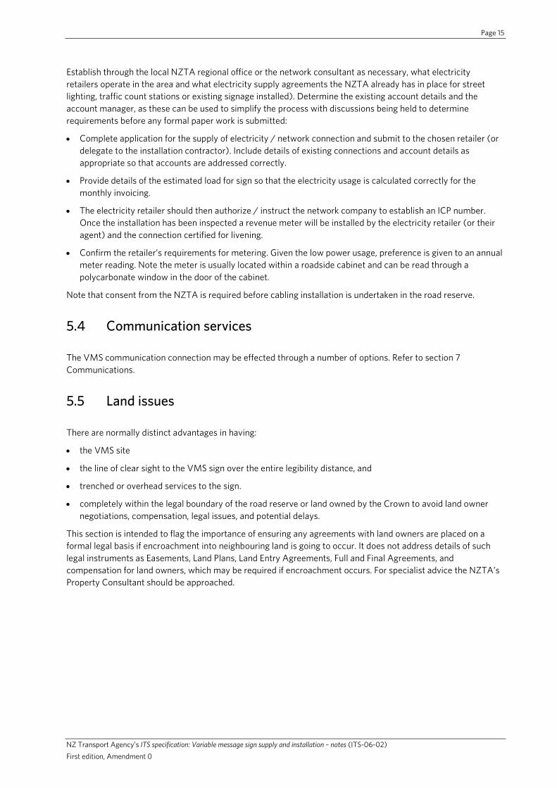
Establish through the local NZTA regional office or the network consultant as necessary, what electricity retailers operate in the area and what electricity supply agreements the NZTA already has in place for street lighting, traffic count stations or existing signage installed). Determine the existing account details and the account manager, as these can be used to simplify the process with discussions being held to determine requirements before any formal paper work is submitted:
• Complete application for the supply of electricity / network connection and submit to the chosen retailer (or delegate to the installation contractor). Include details of existing connections and account details as appropriate so that accounts are addressed correctly.
• Provide details of the estimated load for sign so that the electricity usage is calculated correctly for the monthly invoicing.
• The electricity retailer should then authorize / instruct the network company to establish an ICP number. Once the installation has been inspected a revenue meter will be installed by the electricity retailer (or their agent) and the connection certified for livening.
• Confirm the retailer’s requirements for metering. Given the low power usage, preference is given to an annual meter reading. Note the meter is usually located within a roadside cabinet and can be read through a polycarbonate window in the door of the cabinet.
Note that consent from the NZTA is required before cabling installation is undertaken in the road reserve.
5.4 Communication services
The VMS communication connection may be effected through a number of options. Refer to section 7 Communications.
5.5 Land issues
There are normally distinct advantages in having:
• the VMS site
• the line of clear sight to the VMS sign over the entire legibility distance, and
• trenched or overhead services to the sign.
• completely within the legal boundary of the road reserve or land owned by the Crown to avoid land owner negotiations, compensation, legal issues, and potential delays.
This section is intended to flag the importance of ensuring any agreements with land owners are placed on a formal legal basis if encroachment into neighbouring land is going to occur. It does not address details of such legal instruments as Easements, Land Plans, Land Entry Agreements, Full and Final Agreements, and compensation for land owners, which may be required if encroachment occurs. For specialist advice the NZTA’s Property Consultant should be approached.
Page 16
NZ Transport Agency’s ITS specification: Variable message sign supply and installation – notes (ITS-06-02) First edition, Amendment 0
6.0 Choosing the appropriate character height
6.1 Considerations for regional VMS
For regional VMS, once the number of lines has been determined the appropriate character height must be considered. The minimum character height is determined by visibility and the ability of the motorist to read and comprehend the message. This is a function of:
• total message size
• local speed environment.
Lateral position of the VMS
Drivers approaching the sign at the maximum appropriate / legal approach speed should be able to read the message(s) for at least 7 seconds for two line signs, and at least 11 seconds for four line signs.
Variations on VMS readability, distance and character height are acceptable to the NZTA as long as they do not compromise safety. Variations shall not be in conflict with the NZTA’s signage requirements or standards. Queries should be directed to the NZTA National Office Network Operations CIS Manager.
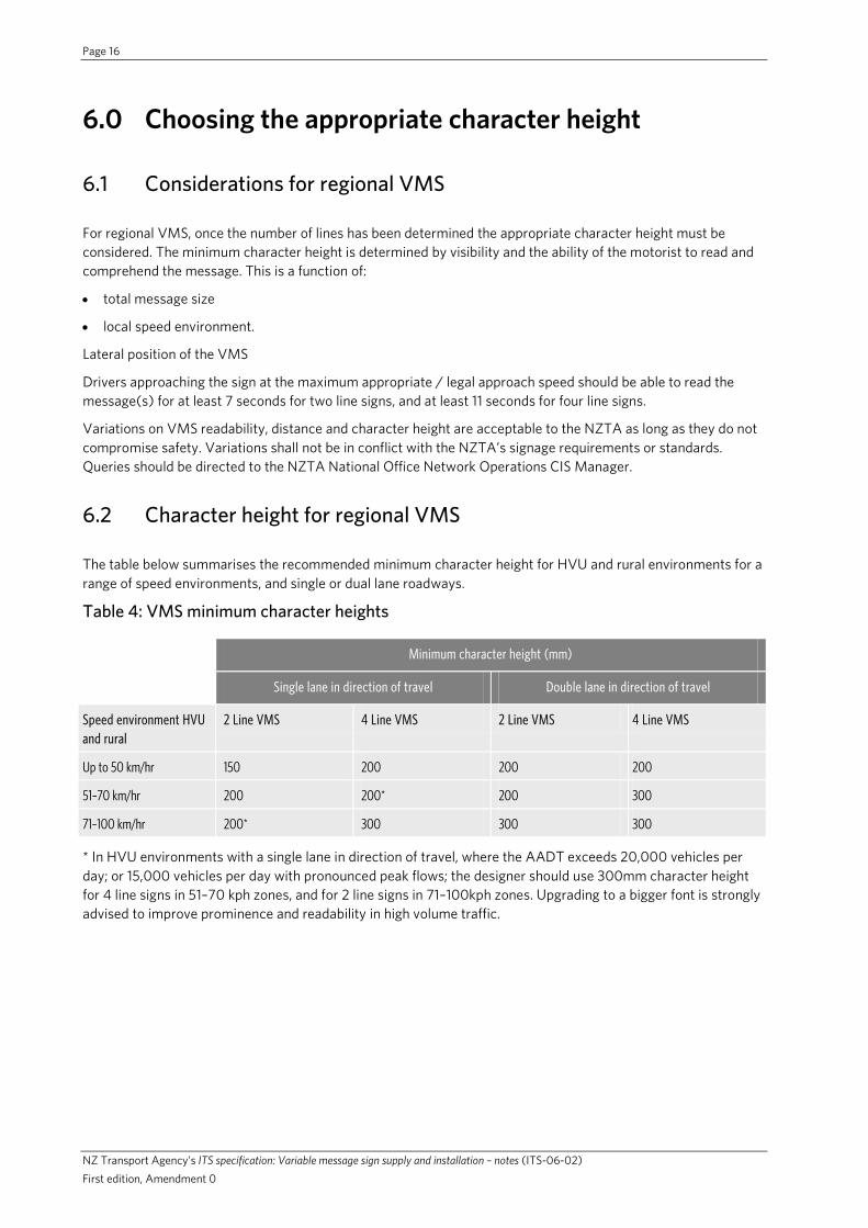
6.2 Character height for regional VMS
The table below summarises the recommended minimum character height for HVU and rural environments for a range of speed environments, and single or dual lane roadways.
Table 4: VMS minimum character heights
Minimum character height (mm)
Single lane in direction of travel Double lane in direction of travel
Speed environment HVU and rural
2 Line VMS 4 Line VMS 2 Line VMS 4 Line VMS
Up to 50 km/hr 150 200 200 200
51–70 km/hr 200 200* 200 300
71–100 km/hr 200* 300 300 300
* In HVU environments with a single lane in direction of travel, where the AADT exceeds 20,000 vehicles per day; or 15,000 vehicles per day with pronounced peak flows; the designer should use 300mm character height for 4 line signs in 51–70 kph zones, and for 2 line signs in 71–100kph zones. Upgrading to a bigger font is strongly advised to improve prominence and readability in high volume traffic.

Page 17
NZ Transport Agency’s ITS specification: Variable message sign supply and installation – notes (ITS-06-02) First edition, Amendment 0
7.0 Communications
A communications link is required to connect the VMS to the NZTA’s national control system. Prior approval from the NZTA’s Customer Information Services Manager is required before any exception is made to this requirement.
In urban locations, there are a range of landline options that can be utilised including;
• Use of any existing NZTA’s communications network
• Leased lines from Telecom NZ or other providers (ADSL).
For regional VMS sites options include;
• Telecom copper line connecting to ADSL (broadband) - preferred option
• Cellular. The NZTA has national communication agreements in place with Telecom.
Other technologies may be considered subject to specific approval from NZTA National Office Network Operations – Customer Information Services Manager.
• Wireless
• Satellite.
Depending on the communication system selected, there may be a need to arrange cabling/trenching to the site. As with the power requirements, consideration should be given to tasking a Telecom contractor with arranging cabling to the site. With regional VMS this is normally arranged by the NZTA’s National Office.
Note that consent from the NZTA is required before cabling installation is undertaken in the road reserve.
Where the VMS is connected to mains power and a copper communication cable, there must be appropriate separation. Where power and communication cable is laid in the same trench for up to 200m, separation of >200mm is required.

Page 18
NZ Transport Agency’s ITS specification: Variable message sign supply and installation – notes (ITS-06-02) First edition, Amendment 0
8.0 Civil design requirements
8.1 Support structure options
This document provides guidance for the civil design of various types of VMS support structures:
• Gantry.
• Single post mounted, including cantilever.
• Dual post mounted.
Figure 3: Typical mounting options for ATMS motorway VMS
Overhead ATMSVMS on gantry
ATMS VMS on cantilever post
ATMS VMS oncentral post

Page 19
NZ Transport Agency’s ITS specification: Variable message sign supply and installation – notes (ITS-06-02) First edition, Amendment 0
Figure 4: Typical mounting options for HVU and rural VMS
HVU/Rural VMS on two posts
HVU/Rural VMS on central posts
HVU/Rural VMS on cantilever posts
8.2 Prescribed design routes
There are two prescribed design routes for VMS support structures.
A. Standard solutions for regional VMS
Standard solutions are generic standardised designs for regional VMS, where neither the sign support system nor the foundation requires further specific engineering design. Standard solutions are provided for:
• Two-post support structures for sign types A, B, C, D and F
• Single post, centre mounted support structures for sign types A, B, C, D and F. These standard solutions do allow for offsets of the supporting pole from the centre of the sign to suit the particular site circumstances, up to the dimension limits given on the drawings.
• Single post rotating flange support structures for sign types C, D and F. These standard solutions are for constrained sites. The VMS can be rotated on the support structure to provide access for planned and reactive servicing.

Page 20
NZ Transport Agency’s ITS specification: Variable message sign supply and installation – notes (ITS-06-02) First edition, Amendment 0
Standard support structure designs are available through the NZTA’s National Office Network Operations – Customer Information Services Manager. The drawings contain standard foundations designs for specified ranges of geotechnical conditions. These standard support structures and foundation designs should be used where the site and ground conditions meet the standard design criteria.
B. Specific engineering design
Signs are subject to specific engineering design. Specific design is required in the following situations:
• Gantry signs.
• Cantilever signs.
• Single post centre mounted signs not meeting the requirements for use of a standard solution.
• Dual post mounted signs not meeting the requirements for use of a standard solution.
8.3 Standard solutions for regional VMS
Where the proposed sign and foundation soil conditions meet the standard design criteria, a “Standard Solution” sign support structure and foundation detail can be used for regional VMS.
Construction drawings for rural/HVU VMS support structure standard solutions are available from the NZTA’s National Office Network Operations CIS Manager.
Where the following requirements are met a standard solution VMS support structure may be used and no specific engineering design is required.
8.3.1 Foundation conditions for regional VMS
Before adopting a standard solution, site investigations shall be completed to confirm that the foundation soil meets the following minimum soil property requirements:
• For non-cohesive soils (sands/gravels) angle of internal friction (Φ) ≥ 25 degrees, and soil unit weight of 16kN/cubic metre, for the dual post mounted signs.
• For non-cohesive soils (sands/gravels) angle of internal friction (Φ) ≥ 33 degrees, and soil unit weight of 18kN/cubic metre, for the single post centre mounted signs.
• For cohesive soils (clay) a Cohesion (c) value of at least 50kPa.
• The ground water level must be at or below the base of the footing.
8.3.2 Face area of VMS sign panel
The standard solutions may only be used for signs that conform to the range of dimensions shown on the drawings. Note that the face panel dimensions must include the bezel, as the wind loading calculations are based on the total face area.
8.3.3 Sign mounting height
The mounting height of standard solution signs, measured from ground level to the bottom edge of the enclosure, on flat ground shall be 3 metres. This is to ensure:
• safety requirements are met when servicing from a ladder
• vandalism is minimised
• design wind loading requirements can be met.

Page 21
NZ Transport Agency’s ITS specification: Variable message sign supply and installation – notes (ITS-06-02) First edition, Amendment 0
8.3.4 Site design wind speed
Site design wind speed for standard solution signs, determined in accordance with AS/NZS1170.2, shall not exceed 49 metres per second.
8.3.5 Structure importance level (AS/NZS 1170.0)
The standard solution sign “structure importance level” (refer to AS/NZS 1170) shall be:
• category 3 for signs greater than 12 square metres (regional VMS are usually smaller than this, but become category 3 if they are located over the carriageway)
• category 2 for signs between 4.7 and 12 square metres
• category 1 for signs less than 4.7 square metres.
For design loadings and other details relating to structure importance, refer to table 5 of these Notes.
8.3.6 Frangible structures
Frangible structures must have an impact performance that meets NCHRP 350, or is deemed by the NZTA’s Traffic and Safety Manager to meet the standard.
The following requirements shall also apply:
• The maximum weight of the above ground support structure and sign is 270kg.
• The post mass must be no more than 27kg per metre.
• Each leg of the structure must incorporate an approved slip base <100mm above ground level.
• Where an impact is likely to come from multiple directions, a multi directional slip base is required.
• The underside of the sign enclosure must be 3.0 metres above ground on a flat site. (The standard design for sloped ground specifies 3.0 metres for the downhill end, and allows the uphill end to be >2.5 metres)
• The roadside post shall incorporate an approved hinge located immediately below the sign enclosure. (Refer to the comment below concerning the NZTA’s P24).
• The power cable shall allow the slip base to function as intended in an impact.
• When a roadside cabinet is mounted behind a post, its position must allow a clear space of at least 3 times the width of any slipbase for the slipbase to activate in an impact. The width of the slipbase is measured in the plane parallel to the road.
Refer to the standard frangible design for a two line, 200mm high character sign, (type D) supported on two posts that may be used for situations within the design criteria.
The following risk based principles have been applied to the two-post standard design solution for sign type D:
• The roadside leg is significantly more vulnerable to collision than the boundary leg.
• If the boundary leg is located at the edge of the road reserve it has a significantly lower risk from collision.
• Because the two legs are approximately 3 metres apart, it is unlikely both will be hit simultaneously.
• Both legs require slipbases
• The roadside leg also requires a hinge.
• Due to the limitations of hinge performance, in a collision the enclosure must be supported on the remaining boundary leg post.
In some specific situations, the NZTA may deem the risk of injury to pedestrians and cyclists from breakaway signposts exceeds the risk to the vehicle occupants. In that case certain requirements of this section may be waived.

Page 22
NZ Transport Agency’s ITS specification: Variable message sign supply and installation – notes (ITS-06-02) First edition, Amendment 0
8.4 Specific engineering design
8.4.1 General
Specific engineering design is required for the following situations:
• Gantry signs.
• Cantilever signs.
• Single post centre mounted signs not meeting the requirements for use of a standard solution.
• Dual post mounted signs not meeting the requirements for use of a standard solution.
Where specific engineering design is required, the design engineer must seek approval of the final sign support design from the NZTA’s Regional Office. The following information must be submitted for this approval:
• Producer Statement Design, in accordance with the requirements of the New Zealand Building Code.
• Construction drawings.
• Construction specification.
• Design calculations.
8.4.2 Access ladder and platform for motorway VMS
For motorway VMS applications, the design of the support structure shall include an external access ladder and platform over the full width of the enclosure. The truss structure shall be 2m high to provide safe head room. An integral ladder hoop is to be provided to the top of the truss. The walkway floor shall consist of checkerboard and be free of trip hazards. The walkway shall include a kickboard and a minimum of two rails on each side. A suitable mesh shall be included on each side to prevent tools and small parts from dropping through to the ground below. The design shall ensure that the enclosure doors are not obstructed by any section of the platform or fittings and are capable of being fully opened. The access ladder shall be capable of being securely locked and the ladder cage shall include measures to prevent trespassers climbing up the external face.
Motorway VMS suppliers may offer enclosures with side entry doors which fully enclose the hardware and any maintenance staff. This has the advantage of allowing maintenance in all weather conditions and fully mitigating any risk of dropped items. For this design, the support structure will only require the access ladder and cage and possibly a small platform.
8.4.3 Applicable design standards
Design of VMS signs and support structures shall be in accordance with the following standards:
AS 1111: ISO metric hexagon bolts and screws
AS 1163: Structural steel hollow sections
AS/NZS 1170: Structural design actions
AS/NZS 1252: High strength steel bolts with associated nuts and washers for structural engineering
AS/NZS 1554: Structural steel welding
AS/NZS 1664: Aluminium structures
AS/NZS 1866: Aluminium and aluminium alloys – Extruded rod, bar, solid and hollow shapes
Page 23
NZ Transport Agency’s ITS specification: Variable message sign supply and installation – notes (ITS-06-02) First edition, Amendment 0
AS/NZS 2312: Guide to the protection of structural steel against atmospheric corrosion by the use of protective coatings
AS/NZS 3678: Structural steel- hot rolled plates, floor plates and slabs
AS/NZS 4506: Metal finishing – Thermoset powder coatings
AS/NZS 4671: Steel reinforcing materials
NZS 3104: Specification for Concrete Production
NZS 3124: Specification for concrete construction for minor works
NZS 3404: Steel Structures Standard
NZS 4680: Hot-dip galvanised coatings (zinc) on fabricated ferrous articles
8.4.4 Foundation design
For the purpose of determining soil foundation capacity, a strength reduction factor (Φ) shall be applied to calculated ideal ultimate soil foundation capacities as follows:
• For signs greater than 12 m2 face panel area, or designated as structure importance level 3, a specific engineering assessment of the soil strength reduction factor (Φ) is required.
• For signs of up to 12 m2 face panel area, that are designated as structure importance category 2: Φ = 0.45.
• For signs of up to 4.7m2 face panel area, that are designated as structure importance category 1: Φ = 0.6.
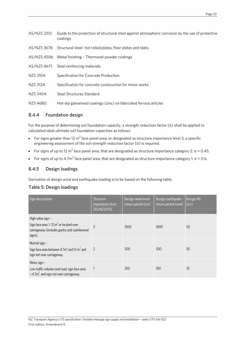
8.4.5 Design loadings
Derivation of design wind and earthquake loading is to be based on the following table:
Table 5: Design loadings
Sign description Structure importance level (AS/NZS1170)
Design wind event return period (yrs)
Design earthquake return period event
Design life (yrs)
High value sign –
Sign face area ≥ 12 m2 or located over carriageway (includes gantry and cantilevered signs).
3 1000 1000 50
Normal sign –
Sign face area between 4.7m² and 12 m2 and sign not over carriageway.
2 500 500 50
Minor sign –
Low traffic volume rural road, sign face area <4.7m2, and sign not over carriageway.
1 250 100 25

Page 24
NZ Transport Agency’s ITS specification: Variable message sign supply and installation – notes (ITS-06-02) First edition, Amendment 0
8.4.6 Design wind speed
The design wind speed shall be derived in accordance with AS/NZS 1170.2: 2002, with the following specific requirements:
a. The design wind speed shall be taken as non-directional.
b. The terrain category of a particular site shall be taken as either 2 (exposed rural terrain) or 1 (exposed open terrain). The value of the terrain height multiplier (MZ, Cat) used must not be not less than that given in Table 4.1 of AS/NZS 1170 for terrain category 2.
8.4.7 Structure serviceability requirements
Under serviceability limit state wind loadings, the top of the sign shall not deflect more than 0.05h where h is the height from ground level to the top of the face panel.
8.4.8 Low temperature performance
Except as noted below, structural steel components in signs located in areas where the LODMAT (Lowest Observed Daily Mean Air Temperature) temperature is below 00 Celsius, as detailed in Figure 2.6.3.1 of NZS 3404:1997, shall satisfy the low temperature performance requirements detailed in Section 2.6 of NZS 3404:1997.
Note: UB and RHS sections that have no welded or bolted connections at their junction with the foundation(s), meet low temperature requirements.
8.4.9 Durability requirements
All components of the sign support structure and foundations are to be constructed such that a period of at least 25 years to first maintenance can be achieved in the specific site environment. For steel components this will normally require galvanising.
The designer must consider:
• Surface corrosion protection zone (Refer AS/NZS 2312 or AS/NZS4506)
• Whether the post needs to be painted and if so any finished colour requirements
8.5 Building consent requirements
As part of implementation of each VMS sign, whether or not a standard solution is adopted, application shall be made to the territorial local authority for exemption from requiring building consent.
If the territorial local authority advises that building consent is required, this shall be obtained prior to construction commencing.

Page 25
NZ Transport Agency’s ITS specification: Variable message sign supply and installation – notes (ITS-06-02) First edition, Amendment 0
9.0 Support structure construction
9.1 Site set-out
Before construction commences the contractor will satisfy the NZTA’s representative that the foundation construction methodology will achieve optimal alignment of the LED viewing angle for approaching motorists.
Horizontal alignment of the VMS shall be achieved by correct alignment of the gantry span for gantry-mounted motorway VMS, or support posts for regional VMS.
9.1.1 Motorway VMS
The optical axis of motorway VMS shall be aligned 5 degrees below the line of sight from the VMS to the driver's eye height at the maximum reading distance (350-400m).
The vertical alignment can be achieved in most situations by using an enclosure having a front face angled down 5 degrees or having a mounting arrangement with the capability for at least 5 degrees adjustment downwards from horizontal. The vertical alignment for gantry mounted VMS can be achieved by setting the offsets to the top and bottom mountings to align the front face of the sign at the correct vertical angle for the road vertical alignment.
The horizontal alignments for straight and curved approaches are illustrated below.
For curved approaches, the VMS must be aligned to ensure:
• At the maximum reading distance the inside edge of the curve is within the cone of visibility, and
• Approaching the VMS, the outside edge of the curve remains within the cone of visibility for as long as possible

Page 26
NZ Transport Agency’s ITS specification: Variable message sign supply and installation – notes (ITS-06-02) First edition, Amendment 0
Figure 5: Optimum alignment for a motorway VMS on an overhead gantry
VMS alignment for straight approach
Plan view
VMS alignment for curved approach
Side view
In the solid amber area, a VMS message is visible to drivers until they exit the lower boundary of the
‘cone of visibility’.

Page 27
NZ Transport Agency’s ITS specification: Variable message sign supply and installation – notes (ITS-06-02) First edition, Amendment 0
9.1.2 Regional VMS
Regional VMS are normally mounted on the side of the roadway on the left hand side of approaching traffic, For a straight approach, the offside edge of the cone of visibility should be aligned down the road reserve parallel with the road.
For VMS mounted some distance beyond a left or right hand curve, alignment should maximise the time that travellers remain within the cone of visibility as illustrated below.

Page 28
NZ Transport Agency’s ITS specification: Variable message sign supply and installation – notes (ITS-06-02) First edition, Amendment 0
Figure 6: Optimum alignment for a regional VMS on a roadside support structure
VMS alignment for straight road
VMS alignment for curved roads
For site set-out use 20° cone (10° either side if optical axis as shown in orange)
Plan view

Page 29
NZ Transport Agency’s ITS specification: Variable message sign supply and installation – notes (ITS-06-02) First edition, Amendment 0
9.2 Unforeseen foundation conditions for regional VMS
The Contractor is to be familiar with the foundation soil properties assumed in design of each sign, as detailed in the contract documents and these Notes.
If the foundation soil properties encountered during construction differ from those assumed in design, the Contractor is to immediately cease work at the site and bring this to the attention of the NZTA’s representative, who will assess the unforeseen conditions and advise how construction is to proceed.
In practice, for scala penetrometer testing (where this is appropriate for the soil type), the foundation soil is considered adequate if at least three blows are required to advance 100 mm depth, to a minimum depth of one metre below ground level.
In addition to the minimum bearing strength requirement, the foundation soil must fulfil the following requirements:
• Ground water table is below the proposed foundation depth (unless specifically allowed).
• Topsoil, very soft or very loose surface sediments shall not be included in the embedment depth given above. In no case should this be greater than a depth of 200mm.
• No peat is present.
• No soft clay is present.
• There is no loose fill present.
9.3 Construction verification
At completion of the works, the contractor shall supply a Producer Statement – Construction covering the construction of all support structures.
The NZTA’s representative shall verify the adequacy and accuracy of the civil works by undertaking a Civil Site Acceptance Test (Civil SAT) using the relevant current check sheet. An example for regional VMS can be viewed in Appendix 2.
9.4 Traffic management
Temporary Traffic Management (TTM) for the site activities shall conform to the NZTA’s Code of practice for temporary traffic management (CoPTTM).

Page 30
NZ Transport Agency’s ITS specification: Variable message sign supply and installation – notes (ITS-06-02) First edition, Amendment 0
10.0 Post-commissioning documentation
10.1 As-built drawings
As built drawings shall be supplied by sign vendors and contractors and will include:
• Support structures
• Installation elevations/plans
• Cabinet drawings
• Power supply arrangements
10.2 Operating servicing and maintenance manuals
The Contractor shall supply an Operating Servicing and Maintenance Manual for all equipment supplied. This shall be carefully laid out with detailed operating procedures for the equipment and systems, including all software supplied. It shall be written in a format that is easily understood by the intended VMS operators.
The manual shall document in detail the maintenance and service aspects of the equipment on an item-by-item basis. This shall include:
• list of equipment including part numbers and availability
• routine service/maintenance procedures
• troubleshooting guide
• details of fault diagnostic features from the control centre
• other fault diagnostic procedures to be followed
• testing procedures
• software maintenance procedures
• circuit diagrams.

Page 31
NZ Transport Agency’s ITS specification: Variable message sign supply and installation – notes (ITS-06-02) First edition, Amendment 0
11.0 VMS structures inspection and maintenance
11.1 Inspection
Inspection of VMS structures shall be undertaken in accordance with the NZTA’s policies, specifications and guidelines. The VMS structures are classified as ‘Other Structures”.
The scope of the inspection shall include:
• damage (accident, or vandalism)
• condition of the corrosion protection system
• the connection between support structure and cabinet
• weather tightness and security of cabinet
• security of power cable and conduit
• adhesion of the mask to the polycarbonate panel
• obstruction to the motorist’s clear line of sight.
11.2 Maintenance
Maintenance shall be undertaken following the identification of defects, in accordance with the NZTA’s requirements. For VMS structures with frangible slipbases, regular maintenance of bolt tightness is required.

Page 32
NZ Transport Agency’s ITS specification: Variable message sign supply and installation – notes (ITS-06-02) First edition, Amendment 0
12.0 Appendices

Page 33
NZ Transport Agency’s ITS specification: Variable message sign supply and installation – notes (ITS-06-02) First edition, Amendment 0
12.1 Appendix 1 – Site assessment proforma for regional VMS

Page 34
NZ Transport Agency’s ITS specification: Variable message sign supply and installation – notes (ITS-06-02) First edition, Amendment 0
12.2 Appendix 2 – Site acceptance test proforma (civil works)


![Considerations on the sign [hook] and the problem of its](https://img.dokumen.tips/doc/110x75/628d06b179811505044c6cc7/considerations-on-the-sign-hook-and-the-problem-of-its-.jpg)