Embed Size (px)
Citation preview

91-062
ITlru l Floru1111 for an A'pplid-Filckl MPD Thruster1 ),rive d fron i l rpgy C'oii-oWratin E a tionqu ion
Akihiro Sa.,i-In titute of Finidl Science, "'Tohloku University
Sendai. Japaln
aIndYoshihiro Arakawa t
Dl'iartniii.n of A.eronautics, I;niversity of Tokyo,Tokyo, Jap;ian
Abs tract a =electrical conductivity
9 = l,/BzThrust formula for an applied-fi'ld MPD tlihruter ha.s c =0B21/i
been derived fromi the energy conseirvation equalin for IthI. , =electron Hall parameterpropellant plasma flow; the work done Iby electrionageticI { } =rerpresntative valueforces is assumed to be ronverted into the kinetic renrgy ofthe exhaust plasma. Three acceleration iiechanisiiis, i.e. gen- Subncriptseralized Hall acceleration, swirl acceleralion anl self-iagnetic a =anoleacceleration are taken into account. This formula enales one c =cathode, criticalto theoretically obtain the thrust by an applied-fi,,ld MPD e =electronthruster from controllable thruister operation parameters. and ef =effectiveto estimate the contriulitions of the respective acceleration ex =exhaustmechanisms. hall =lIall effect, generalized Hall acceleration
self =self-magnetic acceleration
Nomenclature swirl =swirl acceleration
1. Introductiona =constanta, = r/r,
B =magnetic field in order to realize large-sized, long-term space missions
b =constant such as a space station and a Mars mission, for example,r =constant a high-powered, high-I,, propulsion device needs to be de-
E =electric field veloped. For the above requirements, an MPD thruster is
E' =effective electric field thought to be suitable owing to its high-power potentiality,
E'hat. =effective Hall electric field structural simplicity and high-I,, (higher than 1000 sec) op-
e =charge of electron eration ability. Since electrode erosion is essential to the life
j =current density time of the thruster, steady-state operation is thought favor-
J =total discharge current able in order to increase the input power to the thruster. In
I =length of acceleration region the input power range of tens kilowatts, the discharge cur-
MA =ratio of exhaust velocity to Alfv n velocity rent is usually smaller than 1 kA - the effect of self-induced
m, =ion mass magnetic field on thrust production is not high enough. In
rit =mass flow rate order to increase the performance of an MPD thruster in the
n, =electron number density above operation range, an external magnetic field needs to be
p. =electron pressure applied in the acceleration region.
R,, =magnetic Reynolds number Sasoh and Arakawal l] found that when the thrusterr, ,z =cylindrical coordinate operates under a high applied-field strength and low mass
T =thrust flow rate condition, the effect of azimuthal induced currentii =fluid velocityS =flud veocy on thrust production becomes dominant. They obtained theS=exhast velocit thrust formula for this acceleration mechanisms and found
V =volume that the specific impulse is characterized by a characteristicV0 -=rrgl parameter B 2/im.a =constant0 =1/(n,e) The interaction between the applied magnetic field/Io =pcrmealility in vacuum and the discharge current results in azimuthal electromag-S =,//, I netic force, which causes the swirl motion of the propellant
p =density plasma. The swirl kinetic energy can be converted into the ax-
*Assoriate Professor, ?-i-I KAraihira An. -k,. snlai, ) , J,,n .rn- ial kinetic energy both through the solid nozzle of the thruster
her AIAA (tlie centrifugal force is to be balanced with the static pres-'Proftssnr, 7-3-1 lnngo, nunkyo-k-. T1ky. 113. Jalparn M\ .mr Al A sure gradient), and thle magnetic nozzle formed by the applied
I

91-062
magnetic field. Fradkin et al.l[2 gives (tie thru.it formurla for fullkwin, tlhie components ar, domlinant in the interactionthis acceleration mechanism. The formula is based ,o IIe for ce:conservation of the angular momenltun and that of the ki-netic energy of the propellant plasma flow. (1) Generalized Hall acceleration. An axial electro-
Smagnetic force is produced by the intihraction between theVWhen the discharge current becomes larger I han I kA. azilIutlhal induced current and the radial applied magnetic
the interaction force between the self-induced magneti, field fiell (joH,). As the azimuthlal current is inlduced not onl-"and the discharge current cannot be neglected. The thrust due to the Iall effect but also due t tthle dialnagnetic effect 'i
formula is algebraically obtained by Jalhn.l[3 The forimula is this electruomagnetic acceleration will li reaftcr ,e referred toobtained by integrating the electromiagnetic interaction force as 'generalized lall acceleration.over the interelectrode region. An MPD thruster can ob-tain high thrust performance by increasing the discharge cur- (2) Swirl acceleration. An aziml jilali electromagneticrent through quasi-steady operation etc. (self-field MIPD fice is lpro lrced by the radial supplied discharge currentthruster). Moreover, Tahara et al.ll experimentally found ani the axial applied magnetic field (j, H). 7Tis azimuthalthruster). Moreover, Taicara et a al exroprite strentally fn f rce causes the swirl motio of thle prpellant plasma flow,thance the tapplied perorance of te selffield t a e strengther- resulting in swirl kinetic energy input to it. Although somehance the t t prformace of the self-field ) thrust of the swirl kinetic energy is once he converted into the static
From the above descriptions, there may seem to exist enthl).lpy of the plasma flow, it can finally be converted intothree different acceleration mechanisms whicl are related to a a xial kinetic energy.electromagnetic forces. In order to design the performance (3) Slf- ic acce atin. The ieracn bweenof an applied-field ~PD thruster, however, one needs to esti- the raial spllie discharge current and T e i nteraci han self-eenmate the thrust in a wide operation range of such control- ine r'd mPagnlet c field charge crrnt axial electromagn seticlable operation parameters as applied-field strength, mass iforce (j' ). The srelngth of the sef-n inled magnetic feldflow rate, discharge current andI thruster dimensions. The fncreases proort onally o the sppelinduced magnetic fieldpurpose of this study is to obtain a general formula of the Thi efore, this electromagnetic frce scales with the squarenthrust produced by an applied-field MPD thruster and to Thel ror ishar electromagnetic frce scales with the suaremake clear the interrelationships among the above acceler- low levels (smaller than When th ischrge cprrent is satlation mechanisms. log Icil s ( rme. l l r than ~ 1 kA) this component is usually
negligible.[ 1
2. Generation of Electromagnetic Thrust in an In experiments, the reaction forces of electromagneticApplied-Field MPD ThIruster forces on the propellant plasma flow are exerted both on the
magnetic devices (electromagnets or permanent magnets orBefore categorizing the thrust production mechanisms, both) which produce the applied magnetic field, and on thelet one define the terminologies used in this paper and state discharge current circuit. Also, the hydrodynamic pressurethe assumptions made in this study. In this paper, cylin- exerted on the solid surfaces of the thruster contributes adrical coordinates, r, z- are used. An applied-field MPD thrust component; not ornl the static enthalpy but also thethruster is assumed to have an axisymmetric structure. The swirl kinetic energy of the propellant plasma flow can be con-flowfield of the acceleration region is also assumed axisym- verted into an axial kinetic energy through the solid nozzle.metric. An external magnetic field is applied in the axial andradial direction ('applied magnetic field'). The radial compo- 3. Derivation of Thrust Formulanent of the applied field is assumed much smaller than theaxial one - a slowly diverging magnetic nozzle configuration The energy conversion systems are, as described above, sois assumed. Moreover, axisymmetric discharge current in the complicated that one cannot separate a thrust component ofinterelectrode region intuces azimuthal magnetic field, wich tile total thrust. Instead of calculating the respective thrustwill hereafter be referred to as 'self-induced magnetic field.' components separately, the total thrust is obtained from the
components separately, the total thrust is obtained from theGenerally speaking, the total discharge current for an energy conservation equation.
applied-field MPD thruster is a controllable parameter; inte-re, te rk done y elect agetic forces is assmedgrating the current density over the whole electrode (anode to be converted into the axial kinetic energy of the propellantor cathode) surface yields a controllable constant discharge plasma flon both througlh ti le magnetic nozzle and the solidcurrent. If one set a semi-infinite-long cylindrical control sur- nozle. Neglecting the static entlalpy of t he exha plasma,face in the interelectrode region, the integration of j, over te energ conserva tion etatic e n lp o f is m
the control surface equals the total discharge current. For
this reason, j, is, in this paper, referred to as 'supplied dis- /f. 1charge current.' When a magnetic field is applied in the axial x B) udV = mi:u. (1)direction, azimuthal current is induced by the interaction be- The current density is related to elect ric fiel, magnetictween the applied magnetic field and the supplied discharge field, fluid velocity etc. by the genralized Ohm's law;current (discussed in detail later). Therefore, j, is, in thispaper, referred to as 'induced current.' In the absence of the j = [E + Ow p + u x B - j x B] (2)applied magnetic field, the azimuthal current is not induced.
HI er, one assumes that j=/je < 1. By the order estimation ofIn an applied-field MPD thruster, an electromagnetic the axial component of Eq. (2), j./ja is found of the order of
thrust is generated through the interactions between a sup- a3B, which, therefore, is assumed much smaller than unityplied or induced current component and an applied or self- here. In ihis case, tile azimuthal componen of tlie currentinduced magnetic field component. Generally speaking, the density is related to ihe axial one by,
2

91-062
;= ( 3.,, . + ,B, + 3Bu,.). (3) = I~) + t' (13)
The elec-tromanetic fir e considered here i op--ed In IEq. (13), ' varies from 1/4 to 3/4I, depenling on theof the following thr.o components; 1. )HB, (gen.ra;lized Hall current distribution on the cathode.acceleratiion), 2. jB.H (, irl acrelrration). . ;. B, (scdf-
magnetic accleration). Here. one changes the notations B, and B, into B and,B. respectively. Snii tituting Eqs. (5), (10) and (12) for Eq.
Tlerefore. th: left side of Eq. (1) is expressed ty (1) yields the following quadratic equation;
J(j x B) -udV = (1 + , ) 2 - 2(c,:. - c3, + c)( )Ju - cl'.1 2 = 0. (1.1)
II re.
J(-3jB,u.)dV + (-jB:')d\ + Ji,B,:1'iV (1) OH1-I I aB' B
In the above equation, '-' signs are needed for the electromag- i
netic forces to be in the axially downstream direction. (c! = 2onr ahlIo (16)
The first term of Eq. (-1) is expressed such a; 11
1 .3,,a.h,,U I 'o (17)(-jB, ,)dl = -Bi,, .,nI (5) ', = I2,-r (17)
V - ,-Tr1 (i;) c = ao,', r , Fonnib (18)
In Eq. (5). the value of anh,. which is the ratio of lhe equiv- a lboIjalent volume for the generalized Hall acceleration to io. is of ' = ,i (19)
the order of 0.1 to 1.Neglecting the radial and aziimthal velocity cmponents 2o'"r.
of the exhaust plasma, the representative value of the axial C r i (20)
fluid velocity in Eq. (5) is assumed to be Solving Eq. (1.1). the thrust is calculated by
i. = QlU,O (7)
Here, a, is a constant., the value of which will be determined T = rhu,
later.
The second term of the right side of Eq. (4) is calculated c' - C3,'2 + c, + [(c/ - c3 , + c4) 2 + (1 + Ci I)cs] 1
under the assumption that the plasma rotates as a rigid rotor. 1 + ct "il
(21)/(-j,Bue)dV = 2-j B..U(r)]-2rl<dr (8)
SEquation (21) is transformed as follows:
The representative value of the azimnuthlal fluid velocity is
assumed, such that, Th11 + T,, Tn + T,,l )2 + (22T = + [( ) + T,,,,, (22)
2 2
S ,.1JB.r 1 - (rJ/r.) Here,
S rh 1 + (r/r.)2
STh. - ) Th .. (23)a' JBr (, + ,
- ]rin9 (24)
T,,,.,,, = [ ],T,,,.,,,. (24)Therefore, Eq. (8) is transformed into + 1c
S 1 ,J"-B T,., -- T,,t,. (25)/(-oJ)=r, (10) ,+ .
i(-l .+i 5)IV - --"It))
The parameters which appear in the above equations are
, [ -(r/r) 2 (11) given bya =- - o/r z ( 11)
- 2[1 + (r,/ro)-] 1
The last term of the right side of Eq. (-1) is iransformed 2', - , (26)
into the product of the self-magnetic thrustl 3 1 and the repre- 12
sentative value of the exhaust velocity. ' = a, - (27)
i r 'j3 i (-],)rr ti.li, .JjBl.TIm = b--- - I.o.)] ,J (12)H , (2)
where T ,. ,s
3

91-062
T ( 5. Oper;tion Regimes7 ,,,., , . , = ( 2 - .- , , ' (2, 0
S,,/ ale shows the .tyvical operatii.n parameters input in3. = (- i (l0) lxperimenlts and Ihie respeclive thiust components which are
calculated by the present theory in the cases of some applied-Po,'J field MPD thrusters.
Te.if,nr = 2olb--- (31)i and (25) giv In the thruster operation regime performed by Sasoh and
gen q. (2) along wieth Eqs. (23),f a an pplied-fi5 MPD Arakawa (University of Tokyo),11161l it is seen that the effectthruslr of le generalized Hall aclceeration is dominant. In this case,T/r, which is equivalent to the average exhaust velocity, isexpressed by the claracteristic parameter 7l (see Fig. 1). In4. Estitimtions of the Thrust Components order to obtain the exhaust velocity as the general functionof the characteristic parameter which is applicable for dif.In the absence of the applied magnetic fiehl, Eq (22) is ferent kinds of propellant species, B2 /rii - the characteristict,. b the same as thie well known self-magnetic thrust formula parameter in Ref. [1] - needs to he multiplied by the electri-1iv, by Ja l n] 'I licrefore, c;l conductivity. In the characteristic parameter 4,, to whatextent the azimuthal current is induced is estimated by &B,
1 (3) which scales with the electron Hall parameter. The thruster- (3 operation is made at relatively high-B, low-ti levels (compare
\hn ,; < ,, i.e. at a weak applied magnetic field, E . the (' with the others). The ratio r/,. is 0.69. The effect ofli) ,ee<ons the swirl acceleration is not large here - about 10 % thrustincrea.se. The effect of the self-magnetic acceleration is almost
.,,.,, = (2 )JBr, (33) negligible.
i ih. fr Eq. (33) to lie equal to the Fradkin' forrmula, 2! In the operation regime performed by Fradkin et al.Si edd,', tha"t (Los Alamos Scientific Ialaoratory),[2 1 the effect of the swirlacceleration is found dominant. The maximum value of 1 set
S- ( in the experiment is only .1 % of that in the first case. In other2 words, the applied magnetic field at the input propellant mass
r tle raal coponet of E. (2),flow rate is weak in comparison with the former case.
S L cUnder the conlition that i/ = ( V' and ' = 2 , the, (, + i ) . (35) ratio of Theo to T,,,,,, is calculated from Eqs. (23) and (24)dr as follows:
lence, the exhaust velocity calculated from Eq. (28) is ap-proximately given by Th = P 3 =1. W T, f
= ( )( I Cs( 1 (38)Th ll. ma '(3t6)
hr.Bi = ' -- B- =-4- (39), ( 2 a, ac iL (
shotme = rE, (37) AEq. (36) implies that the exhaust velocity only due to the MA (40)generalized Hall acceleration is twice as high as EI'h,I, x B3, B/uo)drift velocity. R, = ouel (41)
The dependence of E', on B is determined both by the At = 0.5, cs( ) is maximum and is of the order of 0.5.impedance of an MPD thruster and by the characteristics of As is seen from Eq. (38), the ratio increases with increasingthe power supply for the arc discharge. Generally, an applied- exha:st elocity. Moreover, when the propellant mass flowfield MPD thruster is connected with a power supply with a rate is decreased, both d and pA2 (= m,/(e'n,) for a fullyconstant-current profile. In this case, ', varies with B. How- ionized plasma) will increase, thereby enhancing the effect ofever, for example, if the power supply has a constant-voltage the generalized Hall acceleration. Also, the axial length ofprofile, the thruster operates as an electrostatic acceleration the acceleration region is to be small so that the contributionthruster, being identical with a 'Hall-current accelerator' or of the generalized fHall acceleration is large.a 'closed-drift tlhrIstCr.'(5]ed-drift trtr.Tahara et al. (Osaka Ulniversity)[41 combines a self-field
To the generalized Hall acceleration, the exhaust velocity -MPD thruster with an applied magnetic field coil connectedis an important parameter. As is seen from Eqs. (23) and in series with the discharge circuit. In this case, the applied(28), it is expressed just by the characteristic parameter 1l = magnetic field is the function of the discharge current. SinceaB'/l. The ratio ,/,c can be a criterion whether the effect the external magnetic field is applied so that it becomes asof the generalized Hall acceleration is large or not. Under a strong as the self-induced magnetic field, the T,,, and T,,,,typical condition that 44 = 2/0, (e.g. from the data of Fig. are al'ost equal. From Eqs. (2.t ) and (25), the ratio of T,,1, r,/r, = 0.38, an,i = 0.58 and a, = 0.-1.), Thon becomes to T,.",,' nder the condition that , < K , is calculated;maximum at p = 0.73,.
TZ '='7- ('< ) (42)T,,,
91-062
are ahnlst equal. From Eqs. (24) and (25), the ratio of 7,,; Acknowledgmentto T,,,,,, under the condition that i' < -c is calculated;
TI- B This work was supported by funding from thlie Ishida, <-- ( )(12) I'oundalion. Nagoya. Japan. This work was partially con-
"" B ducted while the first author belonged to the Department ofpoJ , Aeronautical Engineering, Nagoya University, Nagoya. Japan
S2,rr The authors would like to thank them for offering us a good
b -2opportunity of starting this study.
C 21= o (1.1)
The value of c7 is of the order of unity. Therefore, it is founl
from Eq. (42) that the ratio of these components approxi- References
mately equals the ratio of the self-induced to applied mag-nei -hls.[1] Sasoh, A. and Arakawa, \., Electromagnetic Effects in
an Applied-Field MPD Thruster," Journal of Propul-In the last case. the effect of the generalied IHall accel- sion and Power (to be publihed).
eration is negligible; the maximum value of the characteristicparameter of this case is five orders of magnitude smaller tll [] Franlkin, ). B., Blacktock, A. . oehlling, D. J.,Stratton, T. F., \Villiams, M. and Liewer, I. \V., "Ex-tliat of tle first case.
periments Using a 25-kw Hfollow Cathode Lithlium Va-
5. Conclusion por MPD Arejet," AIAA J., Vol. 8. No. 5, May 1970,pp. 8 8 G-8 9-1.
The formula which gives the thrust produced 1by an [3] Jaln, R. G., Physics of ElFctric Propiulsion, McGraw-
applied-field MPD thruster from the controllable thruster op- Ilill, New York, 1968, Chap 8.eration parameters has theoretically been obtained; the for- [ T Y a Y ik T imula is derived from the energy conservation equation of the ara, II., Kagaya, Y. and Yosi , "Qusipropellant plasma flow. Using this formula, the relative con- tea Magnetoplasadynaic Thruster with Applied
tributions of the generalized Hall acceleration, swirl acceler- Magnetic Fields for Near-Earth Missions," Journal of
ation and self-magnetic acceleration can be estimated. The Propulsion and Power, Vol. 5, No. 6, Nov-Dec. 1989,
relative contributions of the self-magnetic and swirl accelera- p. 713-717.
tions are found to be estimated by the ratio of the self-induced [5] Kaufman, II. R., "Theory of Ion Acceleration withto applied magnetic field strengths. At a moderate applied- Closed Electron Drift," Journal of Spacecraft and Rock-field strength, i.e. when V) is comparable with 0c, a large ets, Vol. 21, No. 6, June 1984, pp. 558-562.effect of the generalized Hall acceleration is obtained under
the conditions that the exhaust velocity is high, the propellant [6] Sasoh. A., "Thruster Performance and Acceleration
mass flow rate is low and the axial length of the acceleration Mechanisms of Steady-State Applied-Field MPD Ar-
region is small. It follows from these results that the general- cjets," Doctoral Thesis, University of Tokyo, March
ized Hall acceleration is found to be suitable for small-sized, 1989.
high-I,p thruster operations.
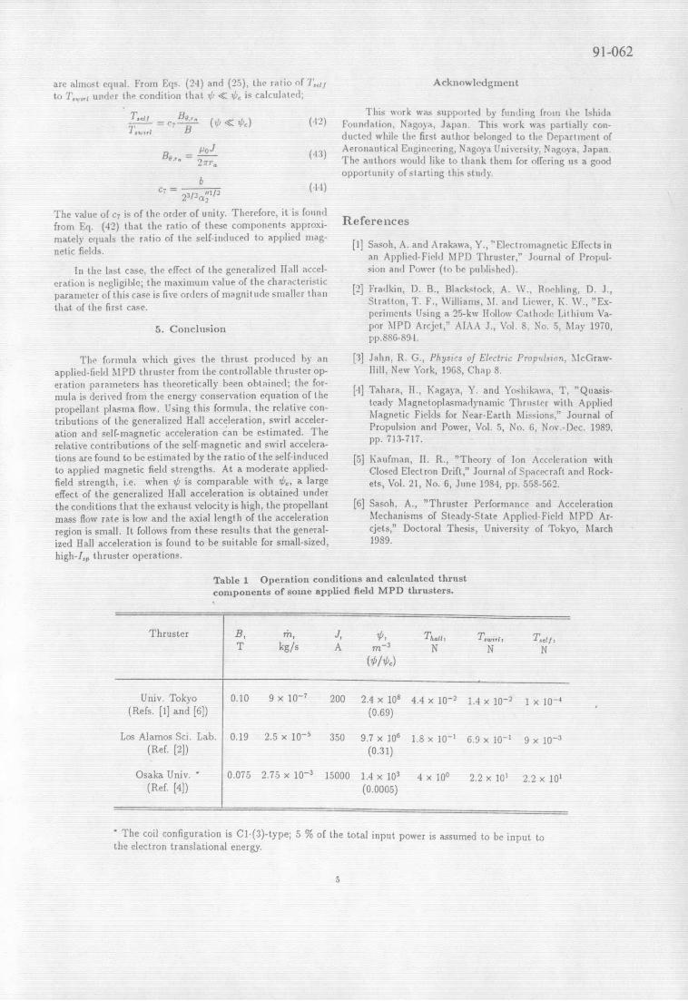
Table 1 Operation conditions and calculated thrustcomponents of some applied field MPD thrusters.
Thruster B, r, J, , , , T,,,,, T e,,T kg/s A m- 3 N N N
Univ. Tokyo 0.10 9 x 10- 200 2.4 x 10⁸ 4.4 x 10- 1.4 x 10⁻² 1 x 10- 4
(Refs. [1] and [6]) (0.69)
Los Alamos Sci. Lab. 0.19 2.5 x 10- 3.50 9.7 x 10⁶ 1.8 x 10⁻¹ 6.9 x 10 9 x 10⁻³(Ref. [2]) (0.31)
Osaka Univ. " 0.075 2.75 x 10- 3 15000 1.4 x 10³ 4 x 100 2.2 x 10' 2.2 x 10'(Ref. [4]) (0.0005)
SThe coil configuration is Cl.(3)-type; 5 % of the total input power is assumed to be input tothe electron translational energy.
5

91-062
8X10
Experiment* H2
N He Theory
) 6- NTfl Ar ,~---- -
4-
F--
2 -v
Tf/'rn
0 1 2 3Xi0
Fig. 1 T/iii-uB2
/iii relation by the applied-fieldMPD thrnuster of Refs. []] and [6]. The theoretical linesare drawn under the following colndition: F = 3.5 x 10-'In,r. = 8 x 10
3n, r(.f = 3 x 10-in. 5 x 10⁻², ii =
2 x 10²kg/(Shns), = 5 x 10 mn3 /Cl 2 x 10 2111.J,
c./(2iFl) A/I2 ,cc = 0.2,.1 = 200A.