Embed Size (px)
Citation preview

ITEC 1011 Introduction to Information Technologies
7. Input / Output
Chapt. 8

ITEC 1011 Introduction to Information Technologies
• URL for the ITEC Student Club:
http://it.yorku.ca
ITEC 1011 Introduction to Information Technologies
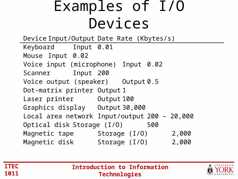
Examples of I/O Devices
Device Input/Output Date Rate (Kbytes/s)Keyboard Input 0.01Mouse Input 0.02Voice input (microphone) Input 0.02Scanner Input 200Voice output (speaker) Output 0.5Dot-matrix printer Output 1Laser printer Output 100Graphics display Output 30,000Local area network Input/output 200 – 20,000Optical disk Storage (I/O) 500Magnetic tape Storage (I/O) 2,000Magnetic disk Storage (I/O) 2,000

ITEC 1011 Introduction to Information Technologies
I/O Configurations (1 of 2)
CPU
I/O module
I/O device
KeyboardMouseVoice input (microphone)ScannerVoice output (speaker)Dot-matrix printerLaser printerGraphics displayLocal area network Optical diskMagnetic tapeMagnetic disk
Can take many forms, e.g.,•Device controller•Disk controller
ITEC 1011 Introduction to Information Technologies
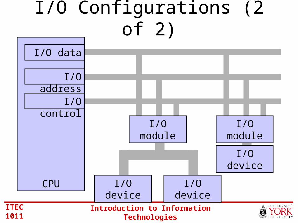
I/O Configurations (2 of 2)
I/O device
I/O deviceI/O device
I/O module
CPU
I/O data
I/O address
I/O module
I/O control
ITEC 1011 Introduction to Information Technologies
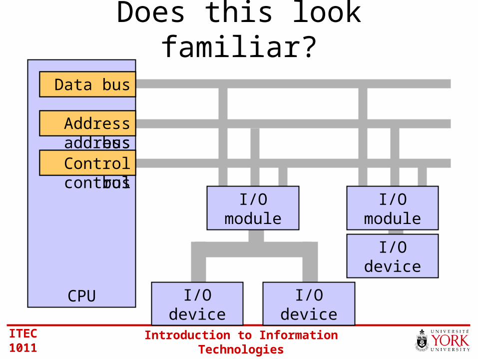
Does this look familiar?
I/O device
I/O deviceI/O device
I/O module
CPU
I/O data
I/O address
I/O module
I/O control
Data bus
Address bus
Control bus

ITEC 1011 Introduction to Information Technologies
A Previous Question
• How is I/O differentiated from memory?
• Two possibilities• Memory-mapped I/O• I/O-mapped I/O
ITEC 1011 Introduction to Information Technologies
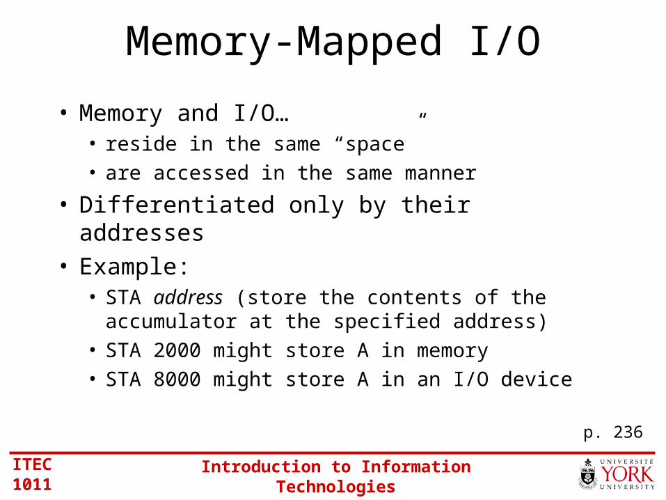
Memory-Mapped I/O
• Memory and I/O…• reside in the same “space”
• are accessed in the same manner
• Differentiated only by their addresses• Example:
• STA address (store the contents of the accumulator at the specified address)
• STA 2000 might store A in memory
• STA 8000 might store A in an I/O device
p. 236

ITEC 1011 Introduction to Information Technologies
Memory MapFFFF
0000
Memory
I/O
ITEC 1011 Introduction to Information Technologies
A Previous Question
• How is I/O differentiated from memory?
• Two possibilities• Memory-mapped I/O• I/O-mapped I/O
ITEC 1011 Introduction to Information Technologies
I/O-Mapped I/O
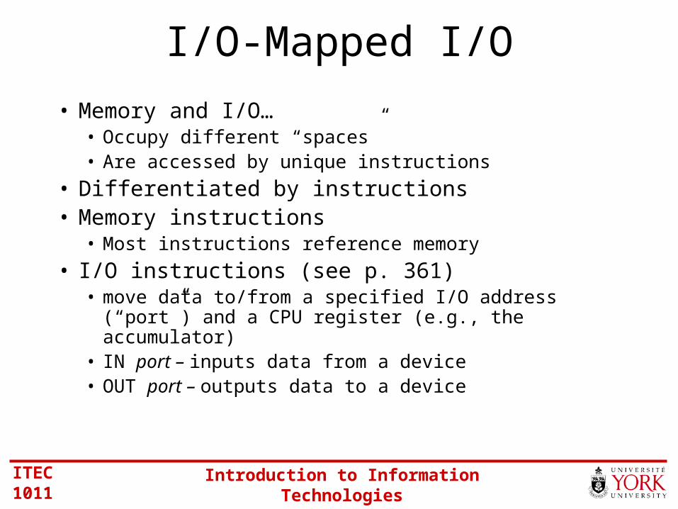
• Memory and I/O…• Occupy different “spaces”• Are accessed by unique instructions
• Differentiated by instructions• Memory instructions
• Most instructions reference memory
• I/O instructions (see p. 361)• move data to/from a specified I/O address (“port”) and a CPU
register (e.g., the accumulator)• IN port – inputs data from a device• OUT port – outputs data to a device

ITEC 1011 Introduction to Information Technologies
Memory Maps
FFFF
0000
Memory I/O
FFFF
0000

ITEC 1011 Introduction to Information Technologies
Implementation of I/O-Mapped I/O
• Typically, access to memory and I/O uses the same address bus and data bus
• A dedicated control bus signal differentiates a “memory cycle” from an “I/O cycle”
• On Intel’s Pentium CPU, this control bus signal is named M/IO• M/IO = 0 memory cycle• M/IO = 1 input/output cycle

ITEC 1011 Introduction to Information Technologies
One of the control bus signals is named M/IO
M/IO
I/O device
CPU
I/O data
I/O address
I/O module
I/O control
Data bus
Address bus
Control bus
Memory

ITEC 1011 Introduction to Information Technologies
Types of I/O
• Programmed I/O
• Interrupt-driven I/O
• Direct memory access (DMA)

ITEC 1011 Introduction to Information Technologies
Programmed I/O
• I/O operations are under direct control of software (program)
• Software initiates the I/O operation• Disadvantage:
• Slow• Uses a lot of CPU resources
• Advantage:• Simple
p. 209

ITEC 1011 Introduction to Information Technologies
Polling
• A form of programmed I/O, wherein device “status” is checked to determine if an I/O operation is needed
• E.g.,• A keyboard can be polled to determine if a key has
been struck and a code is waiting to be read
• Useful when there are a lot of similar devices connected to one system (e.g., hundreds of terminals)

ITEC 1011 Introduction to Information Technologies
Checking Device Status
• The I/O module has registers for data transfers (of course), plus it also has…• Control/command registers
• To configure and control a device
• Status registers• To check the status of a device
• These registers are read/written using• Memory instructions (memory-mapped I/O)
• IN/OUT instructions (I/O-mapped I/O)
ITEC 1011 Introduction to Information Technologies
Types of I/O
• Programmed I/O
• Interrupt-driven I/O
• Direct memory access (DMA)
ITEC 1011 Introduction to Information Technologies
Interrupt-driven I/O
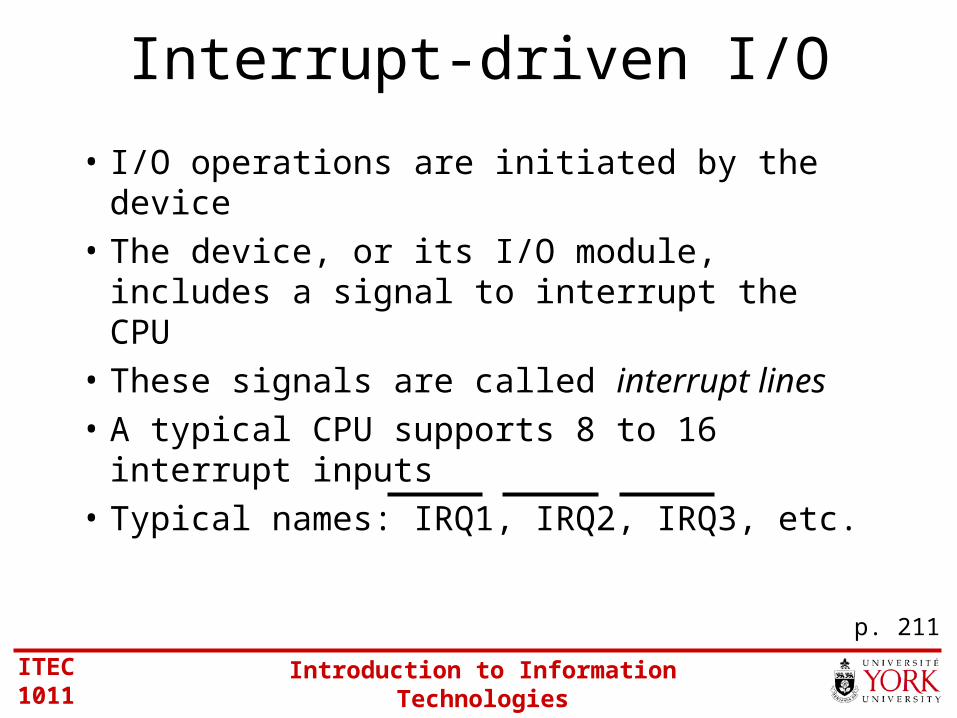
• I/O operations are initiated by the device
• The device, or its I/O module, includes a signal to interrupt the CPU
• These signals are called interrupt lines
• A typical CPU supports 8 to 16 interrupt inputs
• Typical names: IRQ1, IRQ2, IRQ3, etc.
p. 211

ITEC 1011 Introduction to Information Technologies
Servicing an Interrupt
• When an interrupt occurs (and is accepted), the execution of the current program is suspended
• A special routine executes to service the interrupt
• Then, the interrupted program resumes• The service routine is called an interrupt
handler or interrupt service routine (ISR)
ITEC 1011 Introduction to Information Technologies
Saving Registers
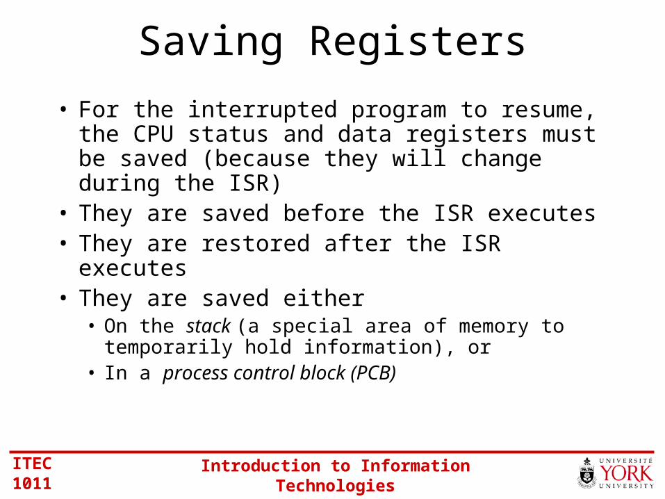
• For the interrupted program to resume, the CPU status and data registers must be saved (because they will change during the ISR)
• They are saved before the ISR executes• They are restored after the ISR executes• They are saved either
• On the stack (a special area of memory to temporarily hold information), or
• In a process control block (PCB)

ITEC 1011 Introduction to Information Technologies
Use of Interrupts
• As an external event notifier
• As a completion signal
• As a means of allocating CPU time
• As an abnormal event indicator

ITEC 1011 Introduction to Information Technologies
Interrupts for External Events
• An interrupt signal occurs when an “event” occurs in a device – an event that requires the CPU’s attention
• E.g., • Keyboard: a key has been hit (the ISR reads the
code for the key)• Notebook computer cover: the cover is closed
(the ISR puts the computer in standby mode)
p. 214

ITEC 1011 Introduction to Information Technologies
Use of Interrupts
• As an external event notifier
• As a completion signal
• As a means of allocating CPU time
• As an abnormal event indicator

ITEC 1011 Introduction to Information Technologies
Interrupts for Completion Signals
• An interrupt signal occurs when a device has completed an operation – and the CPU should know about it
• E.g.,• Printer: the output buffer is empty (the CPU
can send more data)• Scanner: a data transfer is complete (the
CPU/application can proceed to process the image data)
p. 215
ITEC 1011 Introduction to Information Technologies
Use of Interrupts
• As an external event notifier
• As a completion signal
• As a means of allocating CPU time
• As an abnormal event indicator

ITEC 1011 Introduction to Information Technologies
Interrupts for Allocating CPU Time
• Useful on multi-tasking systems – systems that can execute more than one program at a time
• E.g.,• A timer is programmed to interrupt the CPU every 100
µs (for example)
• The ISR is a “dispatcher program”
• Execution switches to another program (for 100 µs), etc.
p. 216

ITEC 1011 Introduction to Information Technologies
Use of Interrupts
• As an external event notifier
• As a completion signal
• As a means of allocating CPU time
• As an abnormal event indicator

ITEC 1011 Introduction to Information Technologies
Interrupts for Abnormal Events
• An interrupt signal occurs when an abnormal event occurs that needs immediate system attention
• E.g.,• A heat sensor near the CPU chip – if the
temperature is too high, an interrupt is generated, the ISR activates the fan near the CPU chip
p. 216
ITEC 1011 Introduction to Information Technologies
Types of I/O
• Programmed I/O
• Interrupt-driven I/O
• Direct memory access (DMA)

ITEC 1011 Introduction to Information Technologies
Why DMA?
• Used for high-speed block transfers between a device and memory
• During the transfer, the CPU is not involved• Typical DMA devices:
• Disk drives, tape drives
• Remember (1st slide)• Keyboard data rate 0.01 KB/s (1 byte every 100 ms)
• Disk drive data rate 2,000 KB/s (1 byte every 0.5 µs)
Transfer rate is too high to be controlled by software executing on the CPU
p. 223
ITEC 1011 Introduction to Information Technologies
How
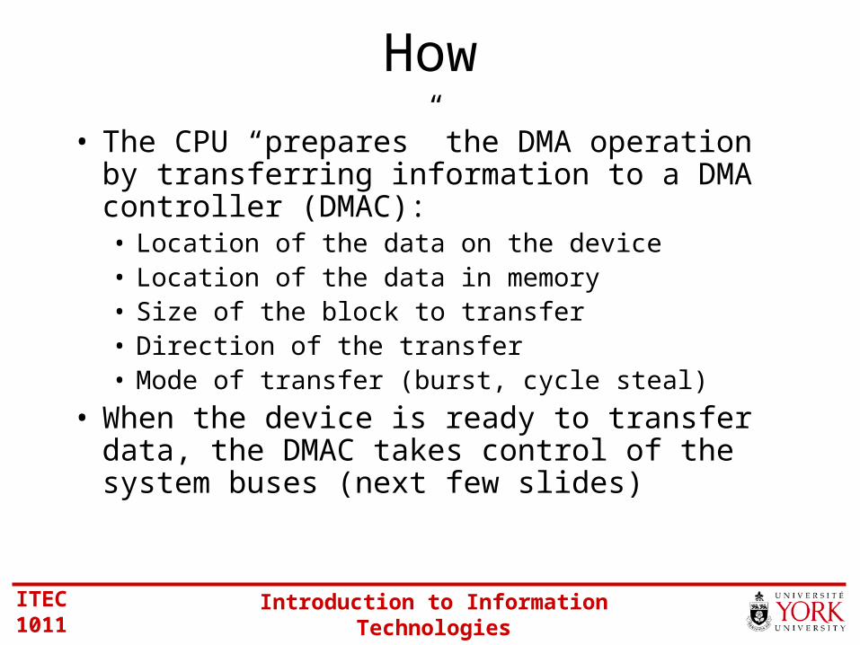
• The CPU “prepares” the DMA operation by transferring information to a DMA controller (DMAC):• Location of the data on the device• Location of the data in memory• Size of the block to transfer• Direction of the transfer• Mode of transfer (burst, cycle steal)
• When the device is ready to transfer data, the DMAC takes control of the system buses (next few slides)

ITEC 1011 Introduction to Information Technologies
“Taking Control” (1 of 2)
CPU DMAC
BR
BG
BGACK
BR
BG
BGACK
BR = Bus request (DMAC: May I take control of the system buses?)
BG = Bus grant (CPU: Yes, here you go.)
BGACK = BG acknowledge (DMAC: Thanks, I’ve got control.)
Control Bussignals

ITEC 1011 Introduction to Information Technologies
• DMAC issues a BR (“bus request”) signal• CPU halts (perhaps in the middle of an instruction!)
and issues a BG (“bus grant”) signal• DMAC issues BGACK (“bus grant acknowledge”)
and releases BR• DMAC has control of the system buses• DMAC “acts like the CPU” and generates the bus
signals (e.g., address, control) for one transfer to take place
• Then…
“Taking Control” (2 of 2)
ITEC 1011 Introduction to Information Technologies
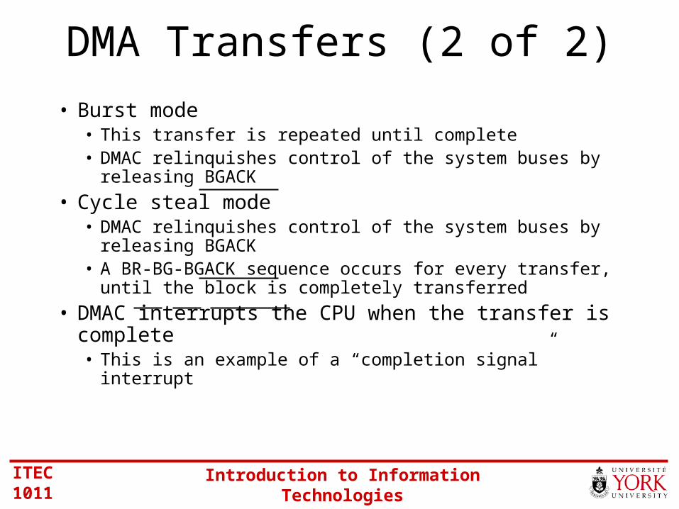
DMA Transfers (2 of 2)
• Burst mode• This transfer is repeated until complete• DMAC relinquishes control of the system buses by releasing
BGACK
• Cycle steal mode• DMAC relinquishes control of the system buses by releasing
BGACK• A BR-BG-BGACK sequence occurs for every transfer, until the
block is completely transferred
• DMAC interrupts the CPU when the transfer is complete• This is an example of a “completion signal” interrupt

ITEC 1011 Introduction to Information Technologies
BR-BG-BGACK Timing
BR
BG
BGACK
CPUcycles
CPUcycles
DMAcycles
time
ITEC 1011 Introduction to Information Technologies
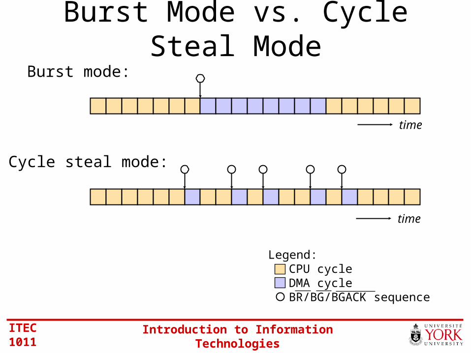
Burst Mode vs. Cycle Steal ModeBurst mode:
Cycle steal mode:
Legend:CPU cycleDMA cycleBR/BG/BGACK sequence
time
time

ITEC 1011 Introduction to Information Technologies
DMA includes all three types of I/O.Let’s see…
Types of I/O
• Programmed I/O
• Interrupt-driven I/O
• Direct memory access (DMA)

ITEC 1011 Introduction to Information Technologies
Program-Controlled I/O (in DMA)
Data busAddress busControl bus
MemoryDMAC
CPU
Disk
The CPU “prepares” the DMAC
ITEC 1011 Introduction to Information Technologies
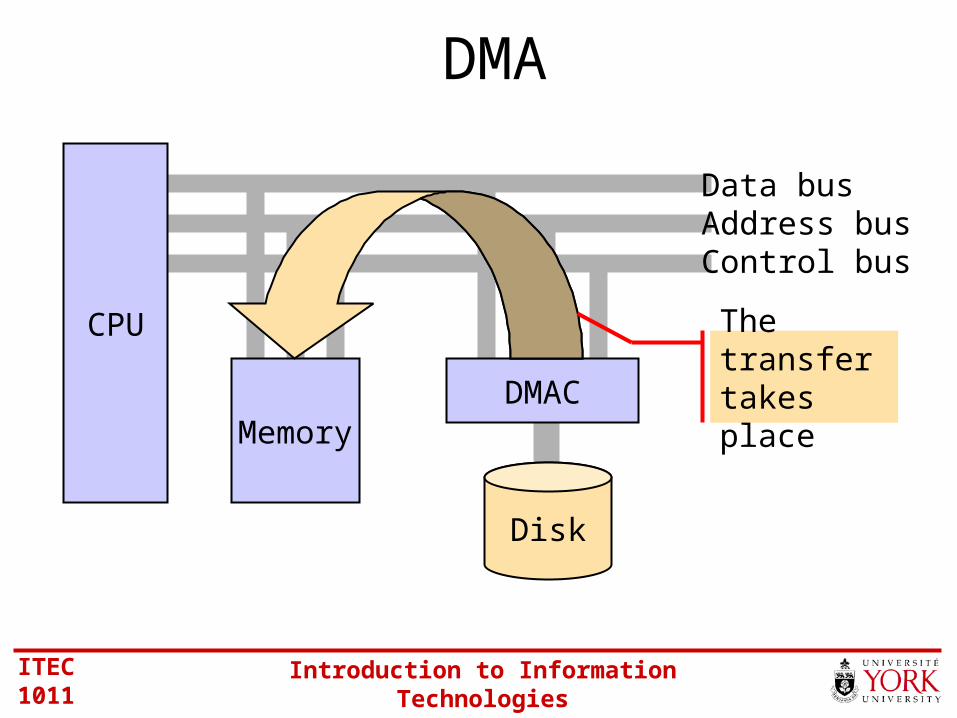
DMA
Data busAddress busControl bus
MemoryDMAC
CPU
Disk
The transfer takes place

ITEC 1011 Introduction to Information Technologies
Interrupt-driven I/O (in DMA)
Data busAddress busControl bus
MemoryDMAC
CPU
Disk
The DMAC interrupts the CPU when the transfer is complete
IRQ

ITEC 1011 Introduction to Information Technologies
I/O System Architectures
• Bus architecture
• Channel architecture

ITEC 1011 Introduction to Information Technologies
Bus Architecture
• Used in (pretty well all) PCs, workstations, and some mainframe computers
• We have already met the data, address, and control buses that connect a CPU to memory and I/O modules
• Collectively, these are the “CPU bus”or “system bus”• Between the I/O modules and I/O devices, an “I/O
bus” is required• A “bus interface” connects one bus to another• Let’s have another look…
p. 228

ITEC 1011 Introduction to Information Technologies
“I/O bus”“Bus interface”“CPU bus”
or“System bus”
CPU-Memory-I/O Architecture
CPUI/O
module
Memory
I/O device
ITEC 1011 Introduction to Information Technologies
I/O System Architectures
• Bus architecture
• Channel architecture
ITEC 1011 Introduction to Information Technologies
Channel Architecture
• An alternative I/O architecture• Used by IBM in their 370/XA and ESA/370
mainframe computers• I/O occurs through an “I/O processor” – the “channel
subsystem”• Frees the CPU for other tasks• Has its own instruction set – “channel control words”• Channel control words stored as “programs”, just like other
CPU instructions• Channel programs transfer data between I/O devices and
memory via DMA
p. 236

ITEC 1011 Introduction to Information Technologies
CPU Memory
Channelsubsystem
Controlunit
Controlunit
Controlunit
DeviceDeviceDevice
Channel paths
Device
I/O Channel
Architecture

ITEC 1011 Introduction to Information Technologies
Thank you