Embed Size (px)
Citation preview

Tom Clark & Rick Hambly Haystack April 2009 0
It’s About Time !!!!!

1
Timing for VLBITiming for VLBI
Tom ClarkTom ClarkNVI/NASA GSFC
mailto: [email protected]
- and -
Rick HamblyRick HamblyCNS Systems, Inc.
mailto: [email protected]
MIT Haystack ObservatoryMay 9–12, 2011

Tom Clark & Rick Hambly Haystack May 2011 2
Long-Term
seconds -
years
Events that occur with a defined
nsec --
minutes
The difference between Frequency and Time
Oscillator•Escapement Wheels & Pendulums•Crystal Oscillators•Cavity Oscillators•Oscillator Locked to Atomic Transition
•Rubidium (6.8 GHz)•Cesium (9.1 GHz)•Hydrogen Maser (1.4 GHz)
Integrator and Display = Clock
•Gears
•Electronic Counters
•Real Clocks
Oscillators and Clocks

Tom Clark & Rick Hambly Haystack May 2011 3
What “Clock”
Performance Does VLBI Need?
The VLBI community (Radio Astronomy and Geodesy) uses Hydrogen Masers at 40-50 remote sites all around the world. To achieve ~10° signal coherence for ~1000 seconds at 10 GHz we need the 2 clocks (oscillators) at the ends of the interferometer to maintain relative stability of:
≈ [10°/(360° * 1010Hz * 103sec)]≈ 2.8 * 10-15 @ 1000 sec.
1

Tom Clark & Rick Hambly Haystack May 2011 4
What “Clock”
Performance Does VLBI Need?
In Geodetic applications, the station clocks are modeled at relative levels ~30 psec over a day:
≈ [30 10-12 / 86400 sec]
≈ 3.5 10-16 @ 1 day
2

Tom Clark & Rick Hambly Haystack May 2011 5
What “Clock”
Performance Does VLBI Need?
To correlate data acquired at 16Mb/s, station timing at relative levels ~50 nsec or better is needed. After a few days of inactivity, this requires:
≈ [50 * 10-9 / 106 sec]
≈ 5 * 10-14 @ 106 sec
Since VLBI now defines UT1, VLBI needs to control [UTC(USNO) - UTC(VLBI)] with an ACCURACY(traceable to USNO)
≈ 100 nsec - 1 μsec
To detect problems, VLBI should monitor the long-term behavior of the Hydrogen Masers (at least) every hour with PRECISION
≈10-50 nsec
3

Tom Clark & Rick Hambly Haystack April 2009 6
Allan Deviation – A graphical look at clock performance
12
3
Allan Deviations of Typical Clocks

Tom Clark & Rick Hambly Haystack May 2011 7
Why do we need to worry about “Absolute Time” (i.e. Clock Accuracy ) in VLBI?
•The ONLY real reason for worrying about “absolute time”
is to relate the position of the
earth to the position of the stars:
•
Generating Sidereal Time to point antennas.
•
Measuring UT1 (i.e. “Sundial Time”) to see changes due to redistribution of mass in/on the earth over long periods of time
(a.k.a. “The Reference Frame”)
•
Knowing the position of the earth with respect to the moon, planets and satellites.
•
Making the correlation and Data Analysis jobs easier

Tom Clark & Rick Hambly Haystack May 2011 8
Why do we need to worry about “Absolute Time” (i.e. Clock Accuracy) in VLBI?
At the stations this means that we will need to pay more attention to timing elements like
•
Frequency Standard and Station Timing
•
The lengths of all signal & clock cables
•
The geometry of the feed/receiver to the antenna.
•
Calibration of instrumental delays inside the receiver and backend. The development of new instrumentation is needed.
•
The care with which system changes are reported to the correlators and the data analysts.

Tom Clark & Rick Hambly Haystack May 2011 9
The Real Signal Path
VLBI Data Analysis
assumes t
he
Geometric C
lock is at th
e Inter
section
of Axes o
f the A
ntenna *
VLBI’s
“REAL”
Clocks (#1)
* Note --
If the axes don’t intersect, then an “offset axis”
model of the antenna is used

Tom Clark & Rick Hambly Haystack May 2011 10
VLBI’s
“REAL”
Clocks (#2)
H-Maser
Phase Cal Ground Unit: Monitors Cable Length
Changes
Counter
Cable Length Transponder
Divide by n
5/10 MHz
Microwave Receiver
1/5/10 MHz
1 Pulse/μsec
DOWN
UP
This is the “clock”
that is used to analyze VLBI data
Quasar
Pulse Generator
ON ANTENNA
CONTROL ROOM
IF

Tom Clark & Rick Hambly Haystack May 2011 11
VLBI’s
“REAL”
Clocks (3)
IF From Microwave Receiver
IF Distributor
Down Converter
5/10 MHz
Clock in Mk5 or Mk6 (XCube)
Formatter
5/10 MHz
Clipper/ Sampler
This is the “clock”
the correlator uses to make fringes
Mark 5 or |
Mark 6 (XCube)
Recorder
H-Maser
Tom Clark & Rick Hambly Haystack May 2011 12
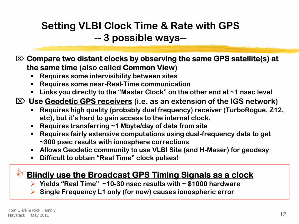
Setting VLBI Clock Time & Rate with GPS
--
3 possible ways--
⌦ Compare two distant clocks by observing the same GPS satellite(s) at the same time
(also called Common View)Requires some intervisibility between sitesRequires some near-Real-Time communicationLinks you directly to the “Master Clock” on the other end at ~1 nsec level
⌦ Use Geodetic GPS receivers
(i.e. as an extension of the IGS network)Requires high quality (probably dual frequency) receiver (TurboRogue, Z12, etc), but it’s hard to gain access to the internal clock.Requires transferring ~1 Mbyte/day of data from siteRequires fairly extensive computations using dual-frequency data to get ~300 psec results with ionosphere correctionsAllows Geodetic community to use VLBI Site (and H-Maser) for geodesy Difficult to obtain “Real Time” clock pulses!
Blindly use the Broadcast GPS Timing Signals as a clockYields “Real Time” ~10-30 nsec results with ~ $1000 hardwareSingle Frequency L1 only (for now) causes ionospheric error

Tom Clark & Rick Hambly Haystack May 2011 13
Timing at an Isolated, Remote VLBI Site --Urumqi in Xinjiang Province, China
UrumqiUrumqi’’s 6s 6--channel channel NASANASA--built TACbuilt TAC
UrumqiUrumqi’’s Chinese s Chinese HH--MaserMaser

Old and New Timing Systems at Wettzell (2009)
Tom Clark & Rick Hambly Haystack May 2011 14
Rick’s Tac32Plus Software
Tom’s old 8 channel “TAC”
HP53132A Counters
Rick’s New 12-
channel “CNS Clock II”

15
An Early Example of “Blind”
GPS Timing with a 6 channel receiver
Tom Clark & Rick Hambly Haystack May 2011

Tom Clark & Rick Hambly Haystack May 2011 16
Before S/A was turned off (8-channel)
. . .

Tom Clark & Rick Hambly Haystack May 2011 17
GGAOGGAO (Goddard Geophysical & Astronomical Observatory)
GPS Trailer
VLBI Trailer & H-Maser5M “MV-3”
VLBI Antenna
GODE GPS GODE GPS AntennaAntennaLocation for new Location for new
VLBI2010 AntennaVLBI2010 Antenna

Tom Clark & Rick Hambly Haystack May 2011 18
How we got ~30 nsec timing in 1995How we got ~30 nsec timing in 1995 even with S/Aeven with S/A
Start with a good timing receiver, like the Motorola ONCOREAverage the positioning data for ~1-2 days to determine the station’s coordinates. With S/A on, a 1-2 day average should be good to <5 meters. Or if the site has been accurately surveyed, use the survey values.Lock the receiver’s position in “Zero-D” mode to this average.Make sure that your Time-Interval Counter (TIC) is triggering cleanly. Start the counter with the 1 PPS signal from the “house” atomic clock and stop with the GPS receiver’s 1PPS.Average the individual one/second TIC reading over ~5 minutes.
______________
All these steps have been automated in my SHOWTIME and in CNS System’s Tac32Plus Software using a barebones PC

Tom Clark & Rick Hambly Haystack May 2011 19

Tom Clark & Rick Hambly Haystack May 2011 20
What happened when the DoD turned off S/A on May 2, 2000.
Sawtooth and Glitches – Some Receiver Defects
Some results obtained with Motorola’s newer low cost timing receiver, the M12+ and M12M
“Absolute” Receiver Calibration
The post-Motorola era & new developments
All that is ancient history. In the new millennium, let’s now discuss . . .

Tom Clark & Rick Hambly Haystack May 2011 21
What happened when S/A went away? Using 8-channel Motorola ONCORE VP Receiver . . .
Note that
Average
is not in the middle of the
max / min
“road”
!

Tom Clark & Rick Hambly Haystack May 2011 22
~3.5 nsec RMS noise
Never Happened

Tom Clark & Rick Hambly Haystack May 2011 23
An example of 1PPS Sawtooth & Bad GlitchesAn example of 1PPS Sawtooth & Bad Glitches MotorolaMotorola’’s low cost UT+ Oncore (v3.1)s low cost UT+ Oncore (v3.1)
-0.100
-0.080
-0.060
-0.040
-0.020
0.000
0.020
0.040
0.060
0.080
0.100
22:29:00 22:30:00 22:31:00 22:32:00 22:33:00 22:34:00 22:35:00 22:36:00 22:37:00 22:38:00
UTC, 4-May-2000
mic
rose
cond
s (n
orm
aliz
ed)
ONCORE UT+ Version 3.1 Short-Term NoiseData logged at CNS Systems by TAC32Plus, May 4, 2000 UTC (Day 125).
©2000 CNS Systems, Inc., plotted by Richard M. HamblyRED = Raw 1PPS with +/- 52 nsec sawtooth BLUE = Sawtooth Corrected Data
Note ~50 nsec glitches every ~19.5 sec

Tom Clark & Rick Hambly Haystack May 2011 24
An example of 1PPS sawtooth with Motorola’s 12-channel M12+ receiver
-0.040
-0.030
-0.020
-0.010
0.000
0.010
0.020
0.030
0.040
01:00:00 01:01:00 01:02:00 01:03:00 01:04:00 01:05:00 01:06:00 01:07:00 01:08:00 01:09:00 01:10:00
Time(UTC)
mic
rose
cond
s (n
orm
aliz
ed)
Rx A - Motorola M12+ V2.0 vs. USNOData logged by Tac32Plus, Aug 8, 2002 UTC (Day 220).©2002 CNS Systems, Inc., plotted by Richard M. HamblyRED = Raw 1PPS BLUE = Sawtooth Corrected Data
COPYRIGHT 1991-2002 MOTOROLA INC.SFTW P/N # 61-G10268ASOFTWARE VER # 2SOFTWARE REV # 0SOFTWARE DATE AUG 14 200MODEL # P283T12NR5HWDR P/N # 2SERIAL # P030XYMANUFACTUR DATE 2G13
~26 nsec p-to-p
~1.5 nsec RMS noise (after applying
sawtooth correction)

Tom Clark & Rick Hambly Haystack May 2011 25
What is the sawtooth effect ????
•For the older Oncore, F=9.54 MHz, so the 1/F sawtooth has a range of +/-
52 nsec (104 nsec peak-to-peak)
•The newer M12+ & M12M have F ≈
40 MHz, so the sawtooth has been reduced to +/-
13 nsec (26 nsec).
IN
1PPS OUT
1 PPSClockEdge
1/FClockEdge
RS232
MASTEROSCILLATOR & CLOCK
RFSTUFF
LOs
DSP STUFFSamplersCorrelatorsIntegrators
Computer
Looooonnnngggg CounterFreq = F
START REGISTER
STOP REGISTERLATCH
These are derived from the same 1/FSignal source, so they are locked to each other.
Unless 1/F is a "perfect" multiple of 1second,the 1PPS will have a sawtooth "walk"
Serial message tells error +/- 1 nsec
CRYSTAL

Tom Clark & Rick Hambly Haystack May 2011 26
VLBI’s
annoying problem caused by the sawtooth timing error
When the formatter (Mark 5 sampler) needs to be reset, you have to feed it a 1PPS timing pulse to restart the internal VLBI clock. After it is started, it runs smoothly at a rate defined by the Maser’s 5/10 MHz.
The AVERAGE of the 1pps pulses from the GPS receiver is “correct”, but any single pulse can be in error by ±13 nsec (or ±52 nsec with the older VP & UT Oncore receivers) because of the sawtooth.
Once you have restarted the formatter with the noisy 1 PPS signal, you then measure the actual (GPS minus Formatter) time that you actually achieved.
-------------------------------
Or, you can use the 1PPS from a new CNS Clock II which has the sawtooth “dither” removed.

Tom Clark & Rick Hambly Haystack May 2011 27
Errors due to the sawtooth do not compromise VLBI data quality
All the Motorola receivers report the error on the next 1 PPS pulse with a resolution of ~1 nsec as a part of the serial data message.
Tac32Plus reads the HP53131/2 counter and the GPS data message and corrects the answer.
But, wouldn’t it be good if the GPS receiver didn’t have any sawtooth error, and that every 1 PPS pulse could be trusted?
Tom Clark & Rick Hambly Haystack May 2011 28
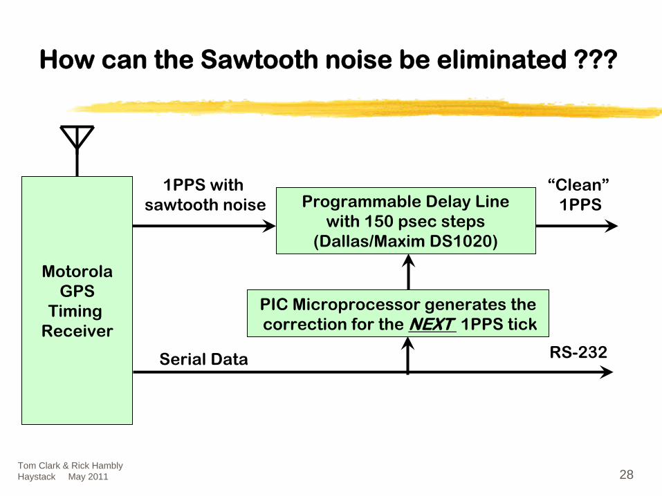
How can the Sawtooth noise be eliminated ???
MotorolaGPS
Timing Receiver
Programmable Delay Linewith 150 psec
steps(Dallas/Maxim DS1020)
1PPS with sawtooth noise
Serial Data
“Clean”1PPS
RS-232
PIC Microprocessor generates thecorrection for the NEXT 1PPS tick

Data available on RS-232, USB 2.0, Ethernet LAN, RS-485 and solid state relay Ports
Ethernet NTP Server for your LANTNC GPS Antenna ConnectorBuffered 1 PPS outputsGPSDO 10 (or 5) MHz output High Performance PPSSteered TCXOSteered Oscillator Utility Functions
Many Options: IRIG-B, Sequencer, Genisys, RS-485 RFID Timecode, Steered OCXO, and Event Recorder Interface.Tom Clark & Rick Hambly
Haystack May 2011 29
The Future is here now! The CNS Clock II
1994 –
2004: the TAC 1PPS Sawtooth Correction Option
Available Since January 2005

Tom Clark & Rick Hambly Haystack May 2011 30
CNS Clock II Block Diagram
PrioritySelect
+Matrix
RS-232USB
1PPS
100PPS
GPS Module
Precision 1PPS
Antenna1PPS
Serial Data
NTP+ Web +FTPTCP+UDPIP Stack
EthernetWith NTP
ProtocolConverter
WaveformGenerator
10MHz
RS422RS422
SSR
IRIG/Option
Steered 10MHzTCXO or OCXO

Tom Clark & Rick Hambly Haystack May 2011 31
Does the hardware 1PPS correction work?
-0.070
-0.060
-0.050
-0.040
-0.030
-0.020
-0.010
0.000
0.010
0.020
0.030
0.040
0.050
00:00 00:01 00:02 00:03 00:04 00:05 00:06 00:07 00:08 00:09 00:10Time (UTC)
Mic
rose
cond
s
CNS Clock II with M12M JB6430 V1.1 with 0.15nsec/div Delay LineHardware vs. Software 1PPS Corrections
Data logged by Tac32Plus, April 19, 2009 UTC (Day 109).©2009 CNS Systems, Inc., plot by Richard M. Hambly
RED = Raw 1PPS GREEN= Hardware Corrected Data BLUE = Software Sawtooth Corrected Data Violet = Correction Difference
9.0 nsec RMS
0.7 nsec RMS
2.5 nsec RMS
2.8 nsec RMS
0.00
0.00
0.00

Tom Clark & Rick Hambly Haystack May 2011 32
Does the hardware 1PPS correction
really work?
y = 0.9408x - 29.206R2 = 0.9986
-50
-45
-40
-35
-30
-25
-20
-15
-10
-15 -10 -5 0 5 10 15Software Command, nsec
Del
ay, n
sec
CNS Clock II with M12M JB6430 V1.1with 0.15nsec/div Delay Line.
Hardware vs. Software 1PPS CorrectionsData logged by Tac32Plus, April 19, 2009 UTC (Day 109).
©2009 CNS Systems, Inc.
NOTE: The 0.15 nsec/step delay line has ~29.2nsec delay bias, as shown in the data.
T(bias) = 10 + (255 * 0.15 / 2) nsec = 29.2 nsec
Tom Clark & Rick Hambly Haystack May 2011 33
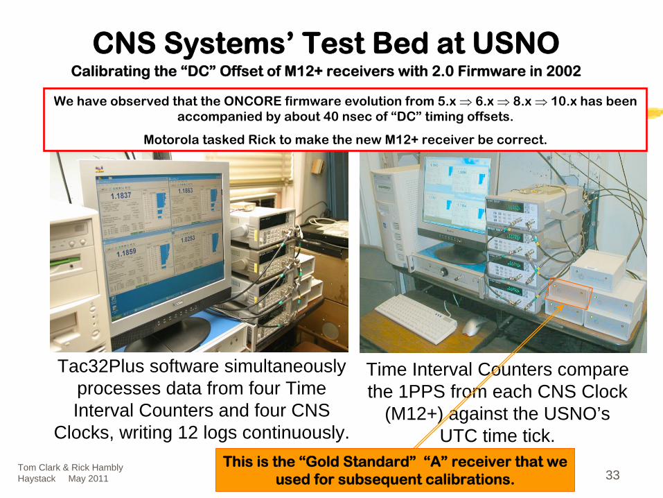
Tac32Plus software simultaneously processes data from four Time Interval Counters and four CNS
Clocks, writing 12 logs continuously.
Time Interval Counters compare the 1PPS from each CNS Clock
(M12+) against the USNO’sUTC time tick.
CNS Systems’
Test Bed at USNO Calibrating the “DC”
Offset of M12+ receivers with 2.0 Firmware in 2002
We have observed that the ONCORE firmware evolution from 5.x ⇒ 6.x ⇒ 8.x ⇒ 10.x has been accompanied by about 40 nsec of “DC”
timing offsets.
Motorola tasked Rick to make the new M12+ receiver be correct.
This is the “Gold Standard”
“A”
receiver that we used for subsequent calibrations.

Tom Clark & Rick Hambly Haystack May 2011 34
Individual M12 Clock Performance “Gold”
Receiver (A) average “DC”
offset = -0.6 ns
-0.040
-0.030
-0.020
-0.010
0.000
0.010
0.020
0.030
0.040
9/4 9/5 9/6 9/7 9/8 9/9 9/10 9/11 9/12 9/13 9/14 9/15 9/16 9/17
Time (UTC)
Mic
rose
cond
s
0.000
0.005
0.010
0.015
0.020
0.025
0.030
0.035
0.040
Noi
se, u
sec
Rx A - Motorola M12+ V2.0 vs. USNOData logged by Tac32Plus, Sep 4 - Sep 16, 2002 UTC (Days 247 - 259).
Data is sawtooth corrected. Averaging Period is 100 seconds.©2002 CNS Systems, Inc., plotted by Richard M. Hambly
Max values within averaging period (Blue)
Min values within averaging period (Green)
Mean values for averaging period (Red)
Average Noise (sawtooth corrected) = 1.2 nsec
COPYRIGHT 1991-2002 MOTOROLA INC.SFTW P/N # 61-G10268ASOFTWARE VER # 2SOFTWARE REV # 0SOFTWARE DATE AUG 14 200MODEL # P283T12NR5HWDR P/N # 2SERIAL # P030XYMANUFACTUR DATE 2G13

Tom Clark & Rick Hambly Haystack May 2011 35
Comparing four M12+ Timing Receivers
-0.020
-0.015
-0.010
-0.005
0.000
0.005
0.010
0.015
0.020
9/4 9/5 9/6 9/7 9/8 9/9 9/10 9/11 9/12 9/13 9/14 9/15 9/16 9/17Time (UTC)
Mic
rose
cond
s
Rx A Rx B Rx C Rx D
Overall bias +2.0 nS
Motorola M12+ V2.0 vs. USNOData logged by Tac32Plus, Sep 4 - Sep 16, 2002 UTC (Days 247 - 259).
Data is sawtooth corrected. Averaging Period is 100 seconds.©2002 CNS Systems, Inc., plotted by Richard M. Hambly
-0.6 nS +3.4 nS+5.3 nS-0.2 nS Average

Tom Clark & Rick Hambly Haystack May 2011 36
What Happened on 9/7/02 ?
September 7, 2002.
This picture is a two hour composite of 85 different photos spanning 21:07 thru 23:10 EDT
on Sept. 7th (01:07 thru 03:10 UTC Sep. 8).
September 8, 2002.
This picture is a four hour composite of 140 different photos spanning 20:00 thru 24:00 EDT
on Sept. 8th (00:00 thru 04:00 UTC Sep. 9).
Each picture was an 87 second exposure with 3 seconds between frames. The trails on the picture are all due to airplanes. The bright loop is from a plane on final approach into BWI airport. Camera = Canon D60 shooting Hi Resolution JPEG at ISO 100 with TC-80 timer. Lens = Sigma f/2.8 20-40 mm set to 20 mm @ f/4.5

Tom Clark & Rick Hambly Haystack May 2011 37
Short Baseline Test (USNO to NASA GGAO)
-20
-15
-10
-5
0
5
10
15
20
25
30
35
40
9/5/02 0:00 9/6/02 0:00 9/7/02 0:00 9/8/02 0:00 9/9/02 0:00 9/10/02 0:00 9/11/02 0:00
UTC
10 M
inut
e A
vera
ge T
imin
g, n
sec
-45
-40
-35
-30
-25
-20
-15
-10
-5
0
5
10
15
Diff
eren
ce b
etw
een
the
two
site
s, n
sec
G G AO M 12+
U SN O M 12+ (A)
Difference, nsec
Sm oothed Difference
C om paring tw o new M otorola M 12+ G PS Tim ing R eceivers over the 21.5 km baseline betw een the U S N aval O bservatory (U SN O ) and the N ASA G oddard G eophysical & A stronom ical O bservatory (G G AO ).
------------------------------------------
Both data sets com pare the G PS tim ing receiver to a local H ydrogen M aser clock. O n both, a linear fit to rem ove constant clock offset and drift has been applied.
Visual Aurora in W ash.DC Area

Tom Clark & Rick Hambly Haystack May 2011 38
Current M12 Receiver Status
All varieties of the M12+ and M12M show similar performance.
All the M12+ receivers, including the 4 receivers in the 2002 test, appear to agree with UTC(USNO) to better than ±10 nsec.
Motorola made a decision to get out of the GPS business. The M12M is now being manufactured by iLotus LTD in Singapore.
GPS performance of the M12M is better than the M12+
The M12Ms show a bias errors up to ~30 nsec as compared with our“Gold” reference Motorola receiver.
The reasons for the biases (Hardware? Firmware?) are unknown.

Tom Clark & Rick Hambly Haystack May 2011 39
What Else is New ?
CNS Clock II includes these standard features:The latest M12M timing receiverEthernet / NTP Time ServerHardware Sawtooth CorrectionSteered TCXO with 10MHz or 5MHz output Steered Oscillator Utility Functions
Options include:Steered OCXO with 10MHz or 5MHz outputIRIG-BOther specialized and custom timing related outputs.
New version of Tac32Plus is available.

Tom Clark & Rick Hambly Haystack May 2011 40
What is Coming Soon ?
CNS Clock II will include new standard features:The u-blox LEA-6T or LEA-7T 50 channel timing receiver with over 2 million effective correlators.New 100/10 BASE-T Ethernet / NTP Time Server with auto crossover detection. Improved Hardware Sawtooth Correction.Improved Steered TCXO with 10MHz or 5MHz output. 10/5 MHz output will become a sine wave at +7dbm nominal. It can be configured between 0 and +10 dbm.
Options will include:A programmable PPS output between 1PPS and 100K pps.
Linux version of Tac32Plus (using QT? Help?).
Tom Clark & Rick Hambly Haystack May 2011 41
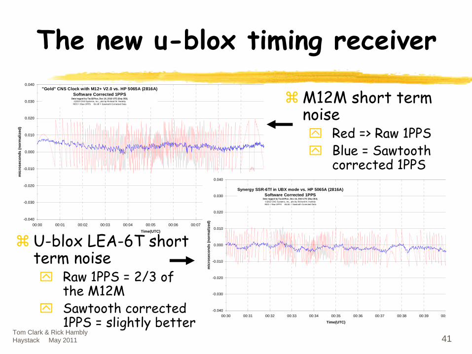
The new u-blox timing receiver
-0.040
-0.030
-0.020
-0.010
0.000
0.010
0.020
0.030
0.040
00:00 00:01 00:02 00:03 00:04 00:05 00:06 00:07 00:08 00:09 00:
Time(UTC)
mic
rose
cond
s (n
orm
aliz
ed)
"Gold" CNS Clock with M12+ V2.0 vs. HP 5065A (2816A)Software Corrected 1PPS
Data logged by Tac32Plus, Dec 19, 2010 UTC (Day 353).©2010 CNS Systems, Inc., plot by Richard M. Hambly
RED = Raw 1PPS BLUE = Sawtooth Corrected Data
-0.040
-0.030
-0.020
-0.010
0.000
0.010
0.020
0.030
0.040
00:30 00:31 00:32 00:33 00:34 00:35 00:36 00:37 00:38 00:39 00:
Time(UTC)
mic
rose
cond
s (n
orm
aliz
ed)
Synergy SSR-6Tf in UBX mode vs. HP 5065A (2816A)Software Corrected 1PPS
Data logged by Tac32Plus, Dec 19, 2010 UTC (Day 353).©2010 CNS Systems, Inc., plot by Richard M. HamblyRED = Raw 1PPS BLUE = Sawtooth Corrected Data
M12M short term noise
Red => Raw 1PPSBlue = Sawtooth corrected 1PPS
U-blox LEA-6T short term noise
Raw 1PPS = 2/3 of the M12MSawtooth corrected 1PPS = slightly better

Tom Clark & Rick Hambly Haystack May 2011 42
Where to get information?
These Slides and related material:
http://gpstime.com
Information on the CNS Clock and the CNS Clock II:
http://www.cnssys.com
To contact Tom: mailto:[email protected]
To contact Rick:
mailto:[email protected], 410-987-7835

Tom Clark & Rick Hambly Haystack May 2011 43
Some Typical Tac32Plus ScreensSome Typical Tac32Plus Screensin Windows 2000/XPin Windows 2000/XP

Tom Clark & Rick Hambly Haystack May 2011 44
Tac32Plus: DISPLAYS UTC TIME
Be Certain that you have selected the POSITION HOLD Be Certain that you have selected the POSITION HOLD ““ZeroZero--DD””
TimkeepingTimkeeping
Mode. Mode. You should You should NOTNOT
be operating in 3be operating in 3--D Navigation mode D Navigation mode !!!!

Tom Clark & Rick Hambly Haystack May 2011 45
Tac32Plus Displays Local Station Sidereal Time (LMST)

Tom Clark & Rick Hambly Haystack May 2011 46
Tac32Plus: DISPLAYING TIME-INTERVAL COUNTER READINGS WITH SAWTOOTH
CORRECTIONS APPLIED

Tom Clark & Rick Hambly Haystack May 2011 47
To Make Sure Tac32Plus is Logging the “true”
Maser-to-GPS Time Interval:
Offset GPS LATE
if needed to be certain that the actual
GPS 1PPS is AFTER the Maser’s 1PPS. Tac32Plus
will do the arithmetic to make the log data be
correct.
Be certain to account for the lengths of all
coax cables.
Allow the Tac32Plus software to correct for
all timing offsets.
Allow software to correct counter reading for 1PPS pulse-to-pulse jitter. Select “OFF”
if using a new CNS Clock II with the Precision 1 PPS Option.

Tom Clark & Rick Hambly Haystack May 2011 48
To Activate the LAN Telnet Link between Tac32Plus and the LINUX PC Field System, Hit Control-T:
Then Click on the check-box and the OK button

Tom Clark & Rick Hambly Haystack May 2011 49
To Use Tac32Plus PC as your Station’s SNTP Network Timer Server:
The new CNS Clock II includes an Ethernet port for use as a low jitter, precise NTP Time Server on your LAN.
See Rick for details.