Embed Size (px)
DESCRIPTION
IT1 U08 - Drawings and Diagrams - Complete
Citation preview

CGLI 2330 Certificate in Electrotechnical Technology Level 2 Inst Tech: Unit 201 – Working Effectively & Safely in an Electrotechnical Environment
Unit 08 - Drawings and Diagrams
The College at Clacton Unit 08 Page 1 August 2011
Drawings & Diagrams
Unit Aims
By the end of the unit participants should be able to:
Identify types of drawings and diagrams as: a) circuit diagrams b) wiring diagrams c) block diagrams d) location drawings e) assembly and detail drawings f) distribution cable route plans/drawings g) site plans h) data sheets and wall charts i) component positional reference systems j) manufacturers’ data and service manuals
(Syllabus Reference: 1.3.03)
Recognize and explain how BS EN 60617 symbols are used in electrical and electronic circuits
(Syllabus Reference: 1.3.05)
Identify and describe, how and why different scales are used to produce drawings, plans and diagrams relevant to the workplace
(Syllabus Reference: 1.3.04)
State the necessity to use drawings, diagrams in conjunction with the related specification
(Syllabus Reference: 1.3.06)
Drawings & Diagrams
Many different types of electrical drawings and diagrams can be identified including:
Block Diagrams (see page 60 of ‘Electrical Installations Level 2 2330 Technical Certificate’)

CGLI 2330 Certificate in Electrotechnical Technology Level 2 Inst Tech: Unit 201 – Working Effectively & Safely in an Electrotechnical Environment
Unit 08 - Drawings and Diagrams
The College at Clacton Unit 08 Page 2 August 2011
Circuit Diagrams (see page 61 of ‘Electrical Installations Level 2 2330 Technical Certificate’)
Wiring Diagrams (see page 61 of ‘Electrical Installations Level 2 2330 Technical Certificate’)
Schematic Diagrams – (working diagrams) (see page 61 of ‘Electrical Installations Level 2 2330 Technical Certificate’)
Assembly Drawings (see page 62 of ‘Electrical Installations Level 2 2330 Technical Certificate’)
Record (As-Fitted Drawings) (see page 62 of ‘Electrical Installations Level 2 2330 Technical Certificate’)

CGLI 2330 Certificate in Electrotechnical Technology Level 2 Inst Tech: Unit 201 – Working Effectively & Safely in an Electrotechnical Environment
Unit 08 - Drawings and Diagrams
The College at Clacton Unit 08 Page 3 August 2011
Location drawings (see page 63 of ‘Electrical Installations Level 2 2330 Technical Certificate’)
Detail Drawings
These are additional drawing produced by the architect to clarify some point of detail. For example, a drawing might be produced to give a fuller description of the suspended ceiling arrangements.
Component Positional Reference
It is important to be able to quickly find the position of the component when assembling or fault finding on a circuit board. A grid is then overlaid on the circuit board and the components are located using a reference system.
Component Value Location
R1 100kΩ A1
TR1 C2
C2 10µF D1
TR2 C1
TR3 C3

CGLI 2330 Certificate in Electrotechnical Technology Level 2 Inst Tech: Unit 201 – Working Effectively & Safely in an Electrotechnical Environment
Unit 08 - Drawings and Diagrams
The College at Clacton Unit 08 Page 4 August 2011
Charts (see page 64 of ‘Electrical Installations Level 2 2330 Technical Certificate’)
Symbols Note
To assist understanding information contained within drawings and diagrams, many symbols are used. It is suggested in the aims for this module that these should comply with BS EN 60617. However, in 2002 the International Electrotechnical Commission (IEC) launched an 'on-line' database format for the symbol library, available on subscription from the IEC web-site. Following this decision, in 2004 CENELEC decided to cease publication of EN 60617 in 'paper' form, to withdraw the then-existing standards and formally to adopt the IEC database without any changes for use in Europe. Consequently the British Standard versions must also now be withdrawn.
IEC 60617 contains graphical symbols for use in electrotechnical diagrams. Parts 2 to 13 of IEC 60617 have been incorporated into a database that currently includes some 1400 symbols. The database is the official source of IEC 60617. It replaces parts 2 to 13 of the previous published version (edition 2) of IEC 60617. The following areas are covered in the database:
Conductors and connecting devices;
Basic passive components;
Semiconductors and electron tubes;
Production and conversion of electrical energy Switchgear, control-gear and protective devices;
Measuring instruments, lamps and signalling devices;
Telecommunications transmission, switching and peripheral equipment;
Architectural and topographical installation plans and diagrams.
The incorporation of the symbols into the database has been accompanied by the addition of a considerable amount of new metadata not present in the previous publication (symbol name, usage, keywords, remarks, etc.) and links to related symbols and application notes. The database also provides classified views (by shape, function and application) and a search facility. It is therefore a much richer and more user friendly tool for those who need to understand and apply graphical symbols in electrotechnical diagrams. The database also contains regular 'snapshots' in PDF format that can be easily downloaded. The database is maintained by a validation team appointed by the IEC National Members.
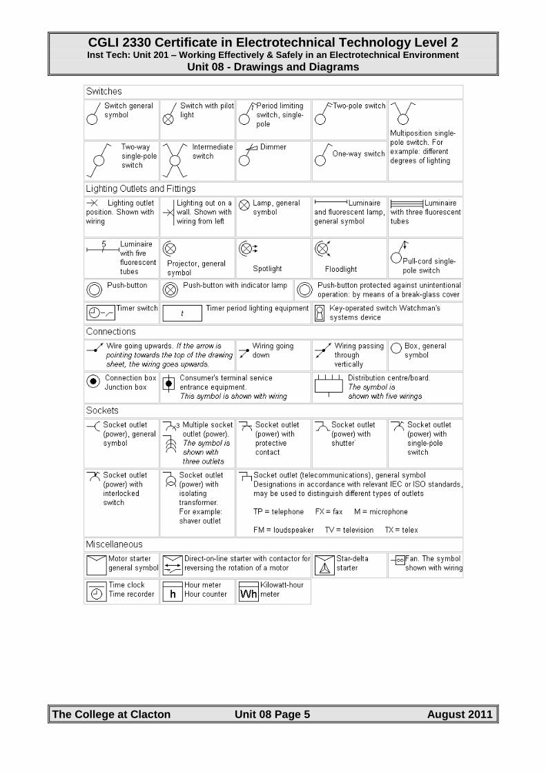
Some the more useful symbols are shown on the following page:
CGLI 2330 Certificate in Electrotechnical Technology Level 2 Inst Tech: Unit 201 – Working Effectively & Safely in an Electrotechnical Environment
Unit 08 - Drawings and Diagrams
The College at Clacton Unit 08 Page 5 August 2011

CGLI 2330 Certificate in Electrotechnical Technology Level 2 Inst Tech: Unit 201 – Working Effectively & Safely in an Electrotechnical Environment
Unit 08 - Drawings and Diagrams
The College at Clacton Unit 08 Page 6 August 2011
Scales
There needs to be plans or drawings of where everything should go if an installation is to be completed accurately
To draw on a piece of paper the size of a whole house or factory would clearly be impracticable so a plan is drawn to scale.
That is, it is first decided how much smaller everything needs to be drawn on the paper. To retain accuracy everything obviously needs to be made smaller by the same amount.
The most common scales in electrical installation are:
1:20, 1:50, 1:100
In each case, everything is 20th, 50th or 100th of its normal size respectively.
A scale drawing is a drawing that represents a real object. The scale of the drawing is the ratio of the size of the drawing to the actual size of the object.
Example:
The length of a building is 100 metres and its width is 75 metres. If 1cm represents 25 metres, what would be the dimensions of the building drawn on a sheet of paper?
Solution:
You can take an intuitive approach to this problem:
100 metres by 75 metres
100 metres = 4cm (HINT: 100 / 25)
75 metres = 3 cm (HINT: 75 / 25)
Therefore, the dimensions would be 4cm by 3cm.
Or you can establish a proportion:
(Notice that the cm are all on the top and the metres are all on the bottom for this solution. Other combinations are possible.)
Length Width
1. = x 1. = y 25 100 25 75
x = 100 y = 75 25 25
= 4cm = 3cm

CGLI 2330 Certificate in Electrotechnical Technology Level 2 Inst Tech: Unit 201 – Working Effectively & Safely in an Electrotechnical Environment
Unit 08 - Drawings and Diagrams
The College at Clacton Unit 08 Page 7 August 2011
Try the following problems:
1) The length of a motorway thruway is 600 kilometres. If 0.5cm represents 50 kilometres, calculate is the length of the motorway on the map. (12cm)
2) The dimensions of a building are 250 metres by 120 metres. If 10mm represents 20 metres on a scale drawing, calculate the dimensions of the building on the drawing. (125mm x 60mm)
3) If one centimetre represents 10 metres, calculate the dimensions used to make a scale drawing of a room 20 metres by 40 metres. (2cm x 4cm)
4) If on a scale drawing a particular dimension is 120mm, using a scale of 1 : 10 this represents how many metres? (1.2 metres)
5) If 1cm represents 75 kilometres on a map, calculate how many centimetres will represent 1500 kilometres. (20cm)
Using Drawings
The most common use of drawings for installation electricians is to show where various accessories, e.g. sockets, switches, lighting points, etc., are to be installed. A previously used example is shown below:
All the accessories are shown on the drawing using appropriate symbols. When actually installing the accessories the electrician will measure on the plan the position of the accessory from a datum point, usually a wall. This is then ‘scaled up’ to give the actual dimension from the wall. In the example above, the socket arrowed is 28mm from the horizontal wall above. If this value is multiplied by the scale, i.e. 75 in this case, the distance from that wall in ’real life’ is found to be 2.1 metres and this distance can be marked, using a tape measure on the actual wall to correctly position the socket outlet.

CGLI 2330 Certificate in Electrotechnical Technology Level 2 Inst Tech: Unit 201 – Working Effectively & Safely in an Electrotechnical Environment
Unit 08 - Drawings and Diagrams
The College at Clacton Unit 08 Page 8 August 2011
However, the problem with this type of drawing is that it is only a two dimensional representation of the actual building which is of course three dimensional. As a result it does not show how high above the floor the accessory should be mounted. Whilst a three dimensional drawing would show this it would, except in the simplest of buildings, be a very complicated drawing. Therefore, we need to refer to the specification to determine mounting heights of accessories.
For example, it may specify that the sockets outlets in rooms other than the kitchen to be fixed at 475mm above f.f.l. (finished floor level) whilst those in the kitchen to be mounted at 1 100mm above f.f.l. Please note that, according to Building Regulations, wall mounted switches and socket outlets must not be lower than 450mm and no higher than 1 200mm above f.f.l. to enable wheelchair users to easily reach them. For each dimension, this refers to the bottom of the accessory for the lower measurement and the top of the accessory for the higher measurement.
Additionally, the specification would have to be referred to for the type and/or style of accessory. For example, is the socket outlet plain white plastic, coloured plastic, brass or satin chrome? Also, the actual make of accessory, e.g. MK, Crabtree, Ashley, etc., may also be specified as well whether the accessory is surface or flush mounted and the type of wiring system to be employed.
For more information see pages 65 to 67 of ‘Electrical Installations Level 2 2330 Technical Certificate’ – revised for the 17th Edition IET Wiring Regulations (ISBN 978 0 435401 09 2).