Embed Size (px)
Citation preview

IST3 Perfusion and Angiography Study
Collaborators Meeting
ESC 2010, Barcelona,
May 27th 2010

Background• Perfusion and angiography imaging used
increasingly in acute stroke• Radiation dose• Problems with renal function and diabetes• Delays treatment • Wide variation in terminology and definitions• Uncertainty about processing and interpretation

NEJM 2009;361:849-57 : Survey of 952,420 adults, USA:Mean 2.4 mSv 1 CT brain scan per yearMedium to high doses in 2% and 0.2% respectively (ie at or above max permitted for radiation worker)
New York Times 15th Oct 2009 Cedars-Sinai Medical Center, …… had mistakenly given up to eight times the
normal radiation dose to 206 possible stroke victims ..involved CT brain perfusion scans. Cedars-Sinai began investigating the procedure in August after a patient noted a “temporary patchy hair loss.”
CT radiation exposure

Radiation Doses: CT, CT angiography, CT perfusion
Procedure Dose background (mSv) radiation
equiv. (years)
CT brain 1.8 1.0CT angio 2.2 1.5-2.0CT perfusion 3-5 1.5-2.5
2x CT, CTA, CTP 22 9
Better evidence required to show that benefits outweigh risks, costs, time

Aims1. Do acute ischaemic stroke patients with imagevidence
of tissue at risk (mismatch) on either CT with CTP or MR DWI/PWI, have a) less infarct growth and b) better functional outcome
if treated with rt-PA than do patients without mismatch?
2. Which perfusion parameter (CBF, CBV, MTT or some derivative), processing method (qualitative, quantitative) and threshold best predicts:a) infarct growth at 24 hours and b) poor functional outcome at six months?
3. Can we clarify imaging features on plain CT or MR DWI that differentiate viable from non-viable tissue?

Progress
• Funding NIHR EME 2009-2012
• Protocol
• Image acquisition guidance
• Image processing established + piloted
• Recruitment
• Questions to be resolved

Imaging Parameters
• Guide Line Perfusion Acquisition Parameters– Based on experience in current studies
• Compatible with STIR recommendation– Acute Stroke Imaging Research Roadmap. Stroke, 2008; 39: 1621 – 1628
– 3 key points – CT perfusion• 80 kvp for the perfusion• Start Imaging soon enough
– Be careful of delay time between injection and acquisition
• Image for long enough– Capture full signal time curve
- CT – non contrast whole brain volume needed – please send as well

Imaging Parameters – rationale and common errorsMR Data Start
(Time)
Finish
(Time)
Injection 16.0 -
AIF 27 48
White Matter
33 53
• Delay required to reduce dose
• At least 1 pre-contrast volume
• Must capture washout in white matter and infarct to construct adequate signal-time curve
Commonest errors:•To long a delay between contrast and acquisition•Not imaging for long enough
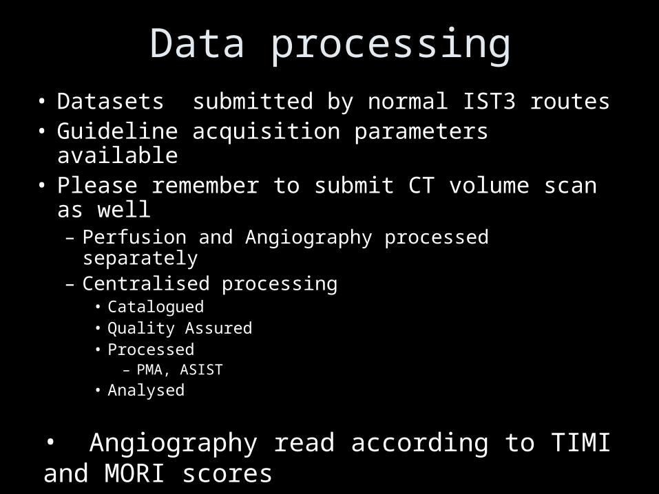
Data processing• Datasets submitted by normal IST3 routes• Guideline acquisition parameters available• Please remember to submit CT volume scan as
well– Perfusion and Angiography processed separately– Centralised processing
• Catalogued• Quality Assured• Processed
– PMA, ASIST
• Analysed
• Angiography read according to TIMI and MORI scores
Perfusion Analysis
• Construct perfusion image
• Register data sets between different time points to map lesion development– MR and CT have different resolution, field of
view and slicing planes– Requires interpolation

IST-3 Perfusion and AngiographyPerfusion analysis
1.Qualitative visual rating of perfusion lesion and mismatch extent
IST-3ASPECTS
for all perfusion parameters including raw data
2. Quantitative tissue perfusion threshold analysis

Benefits of registering CT and MR at different time points – tissue measurements
Pre-randomisation MR DWI imageK Rowland, T Carpenter, J Wardlaw

Measure tissue change in CT attenuation
20 patients, mean age 75.5 ± 12.5 years; mean admission NIHSS 14 ± 7; mean time from stroke to CT 174 mins (range 75-330).All differences ischaemic:contralateral tissue p 0.01

IST-3 Perfusion and AngiographyPerfusion Parameters to be tested
MR perfusion CT perfusion
Raw data Raw data
rCBF rCBF
rCBV rCBV
rMTT (first moment) rMTT (1.45 wrt normal side)
TTP (various thresholds) TTP (1.4 wrt normal side)
Tmax +2 s as per EPITHET
Tmax + 4 s as per EPITHET
ATF ATF
CBFq CBFq (including 12.7 mL/100 g/min)
CBVq CBVq (including < 2.2 mL/100g)
MTTq MTTq

IST-3 Perfusion and AngiographyPerfusion Parameters to be tested
ARE THERE ANY OTHER PARAMETERS THAT
SHOULD BE TESTED???

IST-3 Perfusion and AngiographyPerfusion Parameters to be tested
MR perfusion CT perfusion
Raw data Raw data
rCBF rCBF
rCBV rCBV
rMTT (first moment) rMTT (1.45 wrt normal side)
TTP (various thresholds) TTP (1.4 wrt normal side)
Tmax +2 s as per EPITHET
Tmax + 4 s as per EPITHET
ATF ATF
CBFq CBFq (including 12.7 mL/100 g/min)
CBVq CBVq (including < 2.2 mL/100g)
MTTq MTTq
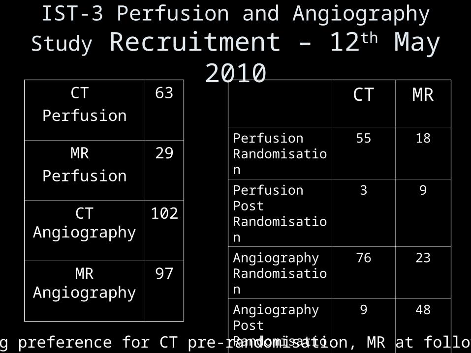
IST-3 Perfusion and Angiography Study Recruitment – 12th May 2010CT
Perfusion
63
MR
Perfusion
29
CT Angiography
102
MR Angiography
97
CT MR
Perfusion Randomisation
55 18
Perfusion Post Randomisation
3 9
Angiography Randomisation
76 23
Angiography Post Randomisation
9 48
Strong preference for CT pre-randomisation, MR at follow up.

Target sample estimate60% will have mismatch overall;70% with mismatch will have infarct growth vs. 30% without
mismatch;rt-PA will reduce infarct growth by 20% in those with, but
not those without mismatch.Difference in infarct growth detectable, + vs - rt-PA,
+ vs - mismatch (80% power, alpha of 0.05): N difference in infarct growth100 27%160 20% 400 15%
We acknowledge that, with at most 300 patients, we may not detect a “rt-PA x mismatch effect”

TARGET SAMPLEPre-randomisation so far:• 73 perfusion • 99 angiography
Rate: • Last year 0.8 per week• Current 1.2 per week
Potential by mid 2011: • 150 - 200 patients, possibly as many as 300

• Ways to encourage recruitment
• Encourage sending of data
• Collaborator meeting
IST3 Perfusion and Angiography Study

IST3 Perfusion and Angiography Study
Thank you


Perfusion analysis – obstaclesCT to MR registration artefact
Change of resolution (MR registered to CT)

Perfusion analysis – obstacles CT to MR registration artefact
Change of slicing plane
CTP registered to MRP CT volume
CTP registered to MRP CT volume

Solution: ROI transformation• Perform registration
as normal• Draw ROI on original
image• Apply transform to
ROI– Requires shape based
interpolation
Change of slicing plane

Down SamplingChange of resolution (MR registered to CT)

Down SamplingChange of resolution (MR registered to CT)
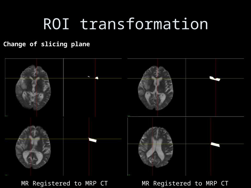
ROI transformationChange of slicing plane
MR Registered to MRP CT MR Registered to MRP CT