Embed Size (px)
Citation preview

IGCNewsletter
INDIRA GANDHI CENTRE FOR ATOMIC RESEARCHhttp://www.igcar.gov.in/lis/nl108/igc108.pdf
IN THIS ISSUE
Technical Articles
• KAlpakkam MINI Reactor
• Semantic Web based Knowledge Representation for Nuclear Reactor Domain
Young Officer’s Forum
• Atomistic Simulations of Displacement Cascades in Y2O3 Single Crystal
Young Researcher’s Forum
• Development of Nanocontainer Impregnated Self-Healing Coatings for Active Corrosion Protection
Visit of Dignitaries
Awards & Honours
ISSN 0972-5741 Volume 108 April 2016

From the EditorDear Reader It is my pleasant privilege to forward a copy of the latest issue of IGC Newsletter (Volume 108, April 2016 issue).
In the first technical article, Shri Manimaran has discussed about the KAMINI reactor and its periodic safety review for relicensing.
Dr. N. M. Meenachi has discussed and analyzed about the semantic web based knowledge representation for nuclear reactor domain in the second technical article.
This issue’s young officer’s forum features an article by Shri Manan Dholakia on atomistic simulations of displacement cascades in Y2O3 single crystal.
Dr. C. Arunchandran has shared his experience in development of nanocontainer impregnated self-healing coatings for active corrosion protection in the Young Researcher’s Forum.
Delegations from Korea Atomic Energy Research Institute and Idaho National Laboratory visited our Centre
We are happy to share with you the awards, honours and distinctions earned by our colleagues.
We look forward to your comments, continued guidance and support.
With my best wishes and personal regards,
Yours sincerely,
Chairman, Editorial Committee, IGC Newsletter
&
Associate Director, Resources Management Group
IGC Newsletter From the Editor

IGC Newsletter
1
From the Director's Desk
From the Director's Desk
FBTR, one of the flagships of our Centre, is continuing to function well, reaching newer milestones. With the completion of safety retrofitting, the reactor can function effectively for more than ten years, and continue to play an important role in testing the fuel, structural materials and special neutron detectors towards development of Fast Reactor programme. The highest power reached so far is 25 MWt/6 MWe and it is proposed to be increased to 34 MWt in the next few campaigns. I am eagerly waiting for the day when we would see FBTR reaching its design power output of 40 MWt.
IGCAR has crossed several important milestones, like the 30th year of criticality and successful operation of Fast Breeder Test Reactor, providing support in getting the safety clearances and R&D towards commissioning of PFBR, working closely with BHAVINI in achieving the goal of first criticality at the earliest, completion of conceptual design of metal fuelled fast breeder test reactor, providing detailed design of two more fast breeder reactors coming up at Kalpakkam with enhanced safety and economy to BHAVINI to enable it to launch the FBR projects at an appropriate stage. The 100 MWt Metal Fuel Test Reactor is also taking shape by getting necessary approvals, completion of preliminary design reports for CFBR 1&2, attainment of hot commissioning of DFRP, faster execution of FRFCF project etc.
KAMINI, the only U233 based operating reactor in the world, is functioning successfully for neutron radiography with high availability. It continues to provide excellent services in testing devices for our Department and more importantly, the space programme.
R&D towards setting up future FBRs with metallic fuel is being pursued by colleagues in the Design Group. Preliminary studies on identification of site and design are in progress. Setting up and commissioning of “Demonstration Facility for Metallic Fuel” is an important step towards this mission.
The operations of CORAL have given immense experience towards setting up Demonstration Fast Reactor Fuel Reprocessing Plant. Activities of FRFCF are gaining momentum. The nuclear island is now fully geared up for the civil construction of plant buildings. Construction of Training Centre, Administration Building, Central Surveillance, Safety & Health Physics building and other service buildings are progressing very well. All the required actions have been initiated for the construction of various plants of FRFCF in a planned manner and procurement of long delivery items. With the dedicated efforts of the limited manpower, we are marching ahead
and we shall see fructification of these efforts and removal of the bottlenecks that are impeding faster progress. The construction of the engineering level pyroprocessing facility is at an advanced stage of completion. We need to work on strict time scales towards achieving completion of mission programmes.
Our untiring efforts on the R&D of newer materials, processes and technologies have paid rich dividends to the mission programmes of the Department, Space, Thermal Power and Fusion programmes. Our expertise and knowledge base in high temperature materials has helped us to develop materials for fusion programme as well as for advanced ultra supercritical thermal power projects.
It is heartening that we made considerable progress in the domains of Electronics and instrumentation. Our efforts in the area of Wireless Sensor Networks have brought international acclaim.
R&D programmes initiated towards I&C design of CFBR 1&2, commissioning of the state-of-the-art 400 nodes, 9600 cores supercomputing cluster system with performance rating of 200 tera flops are certain important milestones.
BARC Training School programme at the Centre is completing 10 years of inception and has consistently provided valuable manpower not only to our Centre but also to other Units of the Department. As a constituent institution under Homi Bhabha National Institute, our Centre at present has many young and talented research scholars and research associates who are pursuing and contributing towards research work. IGCAR has had the honour of receiving number of eminent scientists and technologists whose visits have provided great inspiration for our colleagues. The celebration of the Technology Day involving all technical staff, Peer Review programmes and mentoring of young colleagues were some of the unique programmes related to Human Resources Development and planning for future activities of the Centre.
S. A. V. Satya Murty Director, IGCAR

IGC Newsletter
2
KAlpakkam MINI Reactor
KAMINI Reactor (KAlpakkam MINI Reactor) (Figure 1) is a 233U fuelled, light water moderated/cooled and beryllium oxide reflected low power research reactor designed to operate at a nominal power of 30 kW and is located in the basement of the hot cell of Radio Metallurgy Laboratory. The reactor functions as a neutron source with a flux of 1012 n/cm2s at the centre of core and facilities for carrying out neutron radiography of radioactive and non-radioactive objects and neutron activation analysis of variety of samples is allowed. Experimental facilities consist of three beam tubes with a flux of 108 n/cm2/s, one of them equipped with special setup for radiography of irradiated elements. There are two locations outside the reflector in the reactor tank for irradiation of larger samples at a flux level of 1010 n/cm2/s and one location at the reactor core periphery for short irradiation at a flux level of 1011 n/cm2/s using pneumatic sample transfer system (Figure 2).
Commissioning of the reactor was started after obtaining clearances at various stages from safety authorities in 1995. After obtaining the clearance from safety authorities for operation up to 100 W, fuel loading was done. First criticality was attained on 29 October, 1996. Operation of the reactor at 0.5 W for physics experiments viz., void coefficient of reactivity measurement,
Figure 1: Top view of KAMINI reactor
absolute power calibration using uranium wires and absorber rod worth measurement were completed. Subsequently reactor power was raised to 5 kWt after obtaining clearance from safety authorities and satisfactory operation of systems at high power was demonstrated. After completing the shielding augmentation, reactor power was raised to 30 kWt on 17 September, 1997. With the installation and commissioning of secondary circuit, the commissioning activities were completed and license for regular operation of the reactor at nominal power was obtained from AERB with effect from 1 July, 1998. Based on the feedback from commissioning experience, the technical specification document for reactor operation was modified and forwarded for approval. SARCOP visited the reactor on 21 August, 1998 and took over the safety review of the reactor from PDSC (K).
This reactor is used for neutron radiography of irradiated FBTR fuel, activation analysis and radiation physics research. KAMINI has also been utilized for neutron radiography of pyro devices, meant for space applications and testing of neutron detectors. Presently this is the only operating reactor with this fuel and therefore it serves as a facility to study the physics characteristics of 233U fuelled reactor systems. Neutron radiography of irradiated fuel
Technical Article

IGC Newsletter
3
pins of Fast Breeder Test Reactor (FBTR) up to 1,65,000 MWd/t burn-up and failed fuel was carried out.
In recent years, there has been a pressing demand from ECIL and BARC for testing and calibration of the various types of neutron detectors developed and manufactured by BARC in KAMINI reactor due to the non availability of APSARA Reactor for testing. These detectors have to be tested in the neutron flux of 104 to 1010nv. Two vertical dry tubes of diameter 74 and 103 mm and 3750 mm length with removable shield plugs were installed permanently inside the reactor tank at 35 and 90 cm horizontally from the centre of the reactor core. High temperature fission chambers (HTFC) developed for PFBR were tested in KAMINI up to a neutron flux of 5x10⁹ nv and gamma field of 5x10⁵ R/hr at a temperature of 570 oC. For testing the high temperature fission chamber detectors in KAMINI reactor, a test assembly made up of inconel tube capable of maintaining the detector temperature at 570 oC using electrical heaters is installed on the east side of the reactor in the pool above spent fuel storage stand.
Renewal of license of KAMINI reactor
For renewing the authority to operate the KAMINI reactor, comprehensive safety review of plants was carried out, considering the cumulative effects of plant ageing and irradiation
damage, system modifications, operational feedback, status and performance of safety systems and safety support systems, technical developments, manpower training, radiological protection practices, plant management structure etc. These comprehensive safety reviews are intended to further enhance plant safety throughout the service life of the plant. Periodic Safety Review document was prepared by taking into account improvements in safety standards and operating practices, cumulative effects of plant ageing, modifications, feedback from operating experience, and development in science and technology.
The safety review document was reviewed by the working group constituted by AERB. Based on preliminary review carried out by AERB and from the review outcome, it was observed that the performance of KAMINI has been satisfactory. Several modifications/ replacements have been carried out in order to improve performance and reliability of the systems and enhancement of safety.
With the completion of safety review KAMINI reactor has been available for operation for five more years.
N. Manimaran and colleagues Reactor Facilities
Technical Article
Figure 2: Location of dry tubes and high temperature test set-up

IGC Newsletter
4
Technical Article
Semantic Web based Knowledge Representation for Nuclear Reactor Domain
Knowledge sharing is a systematic process for creating, acquiring, synthesizing, receiving, contributing and utilizing available experience and expertise to achieve the organizational goal. Capturing the knowledge available in each domain and preserving it for the future is one of the prime objectives of knowledge management. According to Oracle, knowledge management system helps to reduce research time, increase resolution accuracy, reduce training time, increasing service volumes, creation of service insight etc. It is a challenging task for any organization to achieve the same knowledge management that is being adopted in many domains. The effort is to employ a suitable mechanism for obtaining and integrating all the expertise, experience and knowledge available within the organization.
Knowledge Management tools are used to capture and transfer knowledge from the experienced members to the new workforce. Knowledge management for a specific domain is implemented by adopting different technologies like knowledge discovery, knowledge sharing, knowledge representation, knowledge engineering, knowledge refinement, and knowledge acquisition. The effective knowledge representation is achieved by overcoming the lack of precision. In the present era, it can be done by enabling the machine to process the available knowledge. As it is not an easy task to teach machines to comprehend natural languages, the way the information is provided to the machine has to be analysed. This is realisable by semantic web, which is an extension of current web where machine understands the concept and processes the knowledge.
Ontology can be defined as
O = (C; T; R; A; I; V; ≤ C; T; σR; σA; iT; iR; iA)
It consists of disjoint sets of concepts (C), types (T), relations (R), attributes (A), instances (I), and values (V). The partial orders ≤ C (on C) and ≤ T (on T) define a concept hierarchy and a type hierarchy respectively. The function σR: R →C2 provides relation signatures (i.e., for each relation, the function specifies which concepts may be linked by this relation), while σA: A→C × T provides attribute signatures. Finally, there are functions iC: C2I the assignment of instances to concepts, iT: T2V, the assignment of values to types, iR: R→ 2I × I, which instances are related by a particular relation, and iA: A →2I× V. This is the value of each attribute for each instance.
Ontology is used to capture the knowledge by using controlled vocabulary of words from the corresponding domain. While sharing the domain knowledge, ontology is used to make the knowledge interoperable and also reusable thereby having seamless exchange
of information. Ontology is developed to provide the common semantics for agent communication so that it acts as a bridge when two or more agents need to communicate or exchange information. The semantic web enables intelligent search by offering greater functionality and inter operability for automatic knowledge extraction by machines. However, the construction of ontology is a time-consuming process requiring expert involvement from both ontology engineering and domain of interest. With the continuous evolvement of knowledge and application needs, ontologies also need to change accordingly which impose a key challenge on ontology maintenance.
System Architecture of KMNuR Web Portal
A knowledge management portal has been developed for FBTR and christened as KMNuR (Knowledge Management for Nuclear Reactor portal (Figure 1). The portal has been developed using Java and the MySQL database at the back end and employs tools like Protégé IDE (Integrated Development Environment) for ontology development and OWLGrEd (Ontology Editor for Compact UML-style OWL Graphic Notation) for UML generation. The objective of the portal is to develop an ontology that would enable effective usage of the contents being made available by the user community. The obtained knowledge about the nuclear reactor is stored in formats like RDF (Resource Description Framework), OWL (Web Ontology Language), UML (Unified Modeling Language). RDF structure represents standard syntax for describing the meaning of data and
OWL represents the standard to describe the relationship between
the data. The knowledge pertaining to FBTR is obtained from data
sources like journals, books, internal reports, existing data in IAEA,
open archives and by taking inputs from nuclear experts. As the
development of ontology is limited in the field of nuclear energy,
emphasis is given to create knowledge representation in the nuclear
reactor domain. Users can select the particular format to retrieve
the knowledge about the nuclear system of their choice. The most
important requirement is to share or reuse the knowledge, which
is achieved by having universal method of expression, uniform
format for data-exchange, syntactic and semantic interoperability.
Universal method of expression and syntactic interoperability can
be achieved by employing XML. However, XML has limitation when
it comes to semantic interoperability. RDF is defined as syntax
independent and its advantage over XML. The object-attribute
structure provides natural semantic units as each objects are
independent entities. OWL is standardized and broadly accepted
language for semantic web. OWL is recommended format by
OAEI (Ontology Alignment Evaluation Initiative) for ontology
matching. For the representation of ontology UML is a good tool

IGC Newsletter
5
Technical Article
which represents static knowledge using class diagram and
dynamic knowledge using UML dynamic and state diagram. UML
representation is easily discernible model for building systems
in object-oriented programming languages and has been widely
adopted by the software engineering community. Hence in the
development of portal we have included RDF, OWL and UML.
The methodology adopted for developing the components of portal for the FBTR domain involves the following steps.
i. Ontology is created by defining the classes, subclasses, object properties, data properties for each system by receiving the knowledge from available sources.
ii. The created ontology is verified and validated by checking the inferred knowledge to remove any logical inconsistency. The verification is carried out by starting any one of the reasoners like Fact++, Hermit and Pellet.
iii. RDF/XML and OWL/XML rendering file options available in the Protégé tool are utilized to generate the RDF, OWL files for the given ontology. These data are captured and stored in the database. This would aid the machine processing by allowing the crawler to crawl the web to extract the knowledge embedded in the system.
iv. The graphical representation of the knowledge is created using Onto_graph and the image is saved in jpeg or gif file format. This is an add_on tool available in the Protégé.
v. OWLGrEd is another program which when executed simultaneously with Protégé tool would enable the user to export the ontology to construct a UML graph.
vi. The collected knowledge and information of each system
is stored in the database for the user and agent program to retrieve process and display the knowledge.
Knowledge Sharing in KMNuR
In the KMNuR web portal, a ‘Knowledge Sharing’ icon has been provided for users to submit the new knowledge to the system. When the information about the knowledge created is available in the machine readable format, details like: name of the submitter, contributing authors are filled in. Once the relevant data is entered, Submit the Knowledge button to the database for approval. The data stored in the database requires approval by the administrator for getting added to the web portal. Moreover when the user inputs a new information, it will be cross checked with the existing information submitted by the user to avoid duplicate entry in the portal. If the information is new, then it is added to the web portal for reusing and sharing of knowledge. As a case study steam generator system of FBTR is taken for analysis.
Development of Ontology Matching Algorithms
When two ontologies differ in representation, they lead to disorder and influence the interoperability of ontologies, because they provide a relatively equal description (or) represent the different viewpoints of the same domain. Entities of ontologies (matched ontology) are used for ontology merging, query answering, data translation, domain knowledge sharing, and also navigating in the semantic web. In addition, ontology merging, integration and alignment can lead to ontology reuse. In continuation with our work of nuclear knowledge management system for nuclear reactor domain a Quick Mapping Evaluator, which is an application program for ontology mapping and matrix rank based ontology were developed.
Figure 1: Main screen of KMNuR showing the knowledge representation of each system, its description, OWL_Graph and UML_Graph

IGC Newsletter
6
Technical Article
Quick Mapping Evaluator (QME)
QME allows the user to choose ontology alignment algorithm like String Equality, Longest Common Subsequence (LCS) and Levenshtein distance for extracting the shared knowledge. The users are allowed to change the type of match making algorithm. The String Equal algorithm has a very high precision, a very poor recall and also a very low F-Measure irrespective of the thresholds. The LCS algorithm steadily increases in precision with increasing threshold, but decreases in recall. The overall F-Measure of the LCS algorithm increases with threshold. The Levenshtein distance also has a steady increase in the precision and decrease in the threshold. The overall F-Measure remains almost consistent at a high value. The Levenshtein distance algorithm has the highest F-Measure and hence gives the best accuracy. The user interface shown in Figure 2 is developed as a multi-tabbed pane with different tabs (panels) displaying different parts of the ontology mapping process. The ontology of electrical power supply and distributed power system logics of the nuclear reactor are matched employing QME, and the metrics (Precision, Recall, F-Measure) with different thresholds are shown in Figure 3. At a threshold of 0.8, the Levenshtein distance algorithm has the highest F-Measure and hence gives the best accuracy.
Matrix Rank based Ontology
Mapping/Alignment techniques are used to find proximity between the entities of two ontologies. Matrix rank based ontology, proposed is an extension of String based ontology matching to calculate the ontology matching. In String based techniques, strings are represented as sequences of alphabets and comparisons are done with respect to the lexical structures. To frame a matrix, string equality algorithm is utilized.
String equality is a similarity defined as:
Each entity of ontology O is matched with other ontology O' and the result of comparison is inserted into a matrix. If entity is exactly matched, then the matrix is filled with ‘1’ else with ‘0’ and is shown in Figure 4. Partial overlap (or) duplicate (or) unique ontology are determined by using matrix ranking methods thereby easing inclusion or exclusion of ontology required for reuse. Two approaches are possible one by merging the ontologies to create a single coherent ontology and the second one is to align the ontology by establishing link between them and allowing them to reuse information from one another.
The following algorithm is used for evaluating the nature of ontology, by finding the number of matching rows and columns in the matrix.
Step 1.Find the match between each node of ontology 1 with each node of ontology 2 and frame the matrix using string based matching. Matrix is filled with ‘1’ if there is a match, else with ‘0’
Step 2.Find the rank of the matrix
Step 2.1 Rank = 0 means the ontology is not matched with each other and it can be excluded
Step 2.2 Rank> 0 and Rank < m (where m is the size of the matrix) means partially overlapped or inclusion
Step 2.2.1. Identity matrix (rank=m) implies that it is a duplicate
Pareto Optimisation
Pareto optimality is a domain independent property that can be used to coordinate distributed ontology. A Pareto rank learning technique is proposed for enhancing multi objective evolutionary optimisation. The goal of multi objective optimisation function is to generate various feasible solutions which are closer to Pareto front from which the best solution could be selected. A Pareto optimal solution cannot be uniquely determined. Usually there exists a set of solutions that all satisfy Pareto optimality which form the Pareto front in the solution space.
The optimisation refers to finding the best possible solution to a problem given a set of limitation or constraint. Finding the mapping between two ontologies, involves computing ontologies at lexical level and conceptual level. In lexical level comparison, string based equality, Leventhein distance and Least common subsequence algorithms are used. Structural level comparison is achieved through probability distribution techniques like Kullback Divergence, Cosine method. Then the Pareto ranking is done to find the optimised solution for ontology matching. Before calculating Kullback Leibler divergence have to calculate the conditional
Figure 2: The alignment of the ontologies – alignment tab

IGC Newsletter
7
Technical Article
probability and frame the probability mass vector function. For this, pre-defined weight age based thesaurus files are used to count instances where attributes are associated with other attributes.
The weight age function is based on the similarity measure across the concepts of the two ontologies which could evaluate a given alignment. The weight age is assigned based on similarity, more similar the mappings to the ideal mapping, more weight they gain. Similarly, if there is no alignment between the two ontologies then the weight assigned is very low. If there exist a partial overlapping then its weight lies in between the maximum and minimum weight. Table 1 summarize the six categories along with the
suggested treatment for each case. The categories are used as the reference to define the user defined file for ontology comparison as a prerequisite. This is primary step to calculate and estimate the values in the user defined thesaurus file for calculating the optimised solution using Pareto optimisation.
The decision to merge is determined by number of similar items in each ontology and thesaurus file. The user sets an acceptable level of similarity and the decision to merge is made by machine. Once the Kullback Leibler, Cosine divergence, Lexical similarity (using string equality, Leventhein distance, Least common subsequence) are calculated. If the results meet the acceptable level, the ontologies are suitable for merging. This is a semi automatic method of merging ontologies and users should give the threshold value. If the minimum value is greater than the threshold then the alignment is accepted or else it is rejected. An algorithm is proposed for finding the matching using Pareto optimization technique and implemented in FBTR system.
Future development efforts would be put to develop appropriate tools for automating the process of converting the accumulated knowledge from the domain expert into machine readable format. The portal would be deployed across WWW to share knowledge relating to the fast breeder reactor enabling the use, share and process the nuclear knowledge. Enhancement and implementation of the portal to cover other forms of nuclear reactors such as thermal, boiled water reactor, pressurised heavy water reactor etc. may be thought of.
N. Madurai Meenachi and colleagues Resources Management Group
Figure 3: Results of comparison of String Equal, LCS and Levenshtein distance using (a ) precision (b) recall (c) F-measure
Figure 4: Schematic diagram for rank based ontology matching
Table 1: Ontology defined for each categories using nuclear reactor
domain
Category Ontology O Ontology O'
I a. Nuclear reaction
b. Uranium a'. fission b'. Plutonium
II Fast Breeder Reactor Thermal Reactor
a. Fission b. Fast Neutrons a'. Fission b'. Slow
Neutrons
III Nuclear Power Plant Nuclear Weapon
a. Fission b. Energy Fission Energy
IV Nuclear Power Plant Submarine
a. Nuclear Reaction
b. Stationary a'. Nuclear Reactor
b'. Mobile
V a. Nuclear Reaction
b. Radiation Artificial
a'. Cosmic Rays
b'. Radiation Normal
VI a. Nuclear Reactor
b. Recycling a'. Waste Management
b'. Recycling

IGC Newsletter
8
Young Officer’s FORUM
Atomistic Simulations of Displacement Cascades in Y2O3 Single Crystal
Shri Manan Dholakia obtained his M.Sc in
Physics from Delhi University. He is from
3rd batch of BARC training School at
IGCAR campus. Presently he is working
as a Scientific Officer in Materials
Science Group. His current area of
research is modeling radiation damage in nuclear materials
using molecular dynamics simulations.
Young Officer's Forum
Resistance to radiation damage is one of the most important properties a material must possess for it to be used as structural material for nuclear reactors. Radiation resistant materials are required for waste forms, for fuel, and also for other applications in the nuclear fuel cycle. Resistance to radiation damage is very important for other fields, such as semiconductor industry also. Radiation resistance can be correlated with material’s ability to overcome or to resist amorphization during and after the irradiation process. This has led researchers to investigate different materials that can be used to achieve this goal. In the present study, we investigate the amorphization characteristics of Y2O3 which is one of the most important ingredient for ODS steels, providing them mechanical strength along with radiation resistance. We study the processes which occur in the Y2O3 system when it undergoes displacement cascades due to irradiation. Our aim is to understand whether it gets amorphized or not under irradiation as well as its ability to recrystallize if it gets amorphized. One can realize that experiments can not give an insight about the different processes which are occurring at the length and times scales (~10 nm, ~100 psecs respectively) typical of displacement cascades. Hence one must resort to simulation techniques and Molecular Dynamics (MD) simulations stand as the best tool for studying the processes which occur at the above said time and length scales.
There are various theoretical criteria developed to understand and predict amorphization characteristics. For example, According to temperature ratio criterion, a system will be resistant to amorphization if Tc/Tm < 0.3 (where, Tc is the crystallization temperature and Tm the melting temperature). For Y2O3 this ratio comes to around 0.3 and we are at a loss whether to call it amorphization resistant or not. Another criteria “bond ionicity criterion” focuses on the ionic and covalent properties of the material. Covalent materials are known to get amorphized more readily than ionic materials. According to bond ionicity criterion if a system has ionicity < 0.47, it would be amorphizable, while materials with ionicity > 0.59 will be always crystalline. Ionicity for Y2O3 is 0.7083 and hence, according to this criterion, it must
be highly amorphization resistant. Another important criterion “topological connectivity” focuses on the geometry and topology of the matrix. According to this, materials that are structurally highly constrained with high topological connectivity for the coordination polyhedra are supposed to be resistant to radiation-induced amorphization. The degree of topological connectivity is measured by the topological freedom f , calculated as,
f=d−Cd−[δ(δ+1) ⁄ 2V−(d−1)((Y/)/(2))−[(p−1)d−(2p−3)]((Z)/(p))
Here, C is the average number of polytopes connected to a vertex, Y , the fraction of edge sharing vertices, Z the fraction of vertices sharing p -sided faces, d the number of degrees of freedom and δ the dimensionality of the structuring polytope. For amorphization resistant materials, f must be smaller than 0. This gives Y2O3 a degree of freedom, f=-6, pointing towards high amorphization resistance. It is evident that these theoretical criteria need to be aided by MD simulations to get a better understanding of the behavior of Y2O3 matrix under displacement cascade.
The current study focuses on structural and defect production aspects of the displacement cascades in Y2O3 single crystal matrix at initial crystal temperature of 300 K. A cubic simulation box equilibrated at an initial temperature of 300 K by using Nosè-Hoover thermostat is used to model the cascade evolution. Interatomic potential developed by Belonoshko et al. which has a Born Mayer term and a Coulomb term with +3 and -2 charges for Y and O respectively is used to model the interactions between atoms. Periodic boundary conditions in all directions and velocity Verlet algorithm for integrating the equation of motion are used for the simulations. A typical displacement cascade starts with the generation of a primary knock on atom (PKA) due to impact of an incident particle such as neutron. This PKA then collides with other atoms, which, in turn collide with others to produce displacement cascade. So, to simulate this process, different PKA energies 0.5, 3 and 5 keV are taken. Since in a real situation, PKA can be initiated in any random direction, and since cascade properties can highly depend upon the PKA’s initial direction, 55 different crystallographic directions for the PKA are taken. These directions correspond to a set

IGC Newsletter
9
Figure 2: Pair correlation function plot for 0.5, 3 and 5 keV PKA
Young Officer's Forum
of 253 independent directions after accounting for the multiplicities of the underlying bcc lattice. Moreover, there are two different atomic species in yttria (Y and O atoms) and hence it is necessary to study the cascade characteristics with both the Y and O atoms as the PKA. A cascade is initiated by imparting the required energy for a PKA – either O or Y atom, in the center of the simulation box.
The simulations show that the Y PKA produces more number of defects as compared to O PKA. This is attributed to the inherent stoichiometry of the Y2O3 matrix. Also, it is observed that the total number of surviving defects is quite similar to that predicted by NRT formula. Thus, in case of Y2O3 larger numbers of defects survive at the end of cascade, as compared to Fe. Many antisite defects are produced but since Y2O3 is predominantly an ionic system, these get annealed out quickly. It is seen that during displacement cascade, a very high temperature ~13000 K reaches in the cascade core. It has to be noted that the oxygen sublattice looses heat energy faster than the Y sublattice. This behavior has important consequence on the way the matrix dissipates the cascade energy.
To see what happens to the local structure of the cascade core, we focus on different studies such as Radial Distribution Function (RDF), Wendt Abraham parameter (Rg), Mean Square Displacement (MSD), Distortion Index and average bond length. Analysis of these studies requires a good insight into the structure and topology of the Y2O3 matrix. The bixbyite crystal structure of Y2O3 can be viewed as comprising of 32 Y ions, 48 O ions and 16 O vacancy positions containing symmetry inequivalent Y1 and Y2 and O atoms sitting at different positions. Alternatively, the unit cell can be viewed as a network of interconnected octahedra (Figure 1), where each Y atom is surrounded by 6 O atoms. Each octahedron is connected via six edges to other YO6 octahedra.Y2 octahedra are connected only to Y1 octahedra, while Y1 octahedra are connected to both Y2 and Y1 octahedra. Each vertex is shared by three edge connected and one corner shared YO6 unit. In Y2O3, the YO6 octahedron is the basic structural unit. The system can be viewed as a network of edge sharing YO6 octahedra (six out of 12 edges are shared), with Y cation at the center being surrounded by six O anions.
The behavior of this network of interconnected YO6 octahedra under displacement cascade is first analyzed by calculating RDF in a sphere of radius 2 nm around the initial position of the PKA. RDF plots are shown in Figure 2 for the three energies. It can be seen that the nearest neighbour Y–O peak is at 0.23 nm, the O–O peak is at 0.29 nm and the Y–Y peak is at 0.35 nm. It can be seen that the crystal gets disordered at thermal spike (when cascade is at its peak- shown by red curve) and then almost recovers its initial state at the end of the cascade. Even for the highest energetic PKA of 5 keV energy, the first three peaks remain visible at tpeak. This is a signature of remnant crystalline order albeit with increased level of disorder in the Y and O ion positions. As the RDF is not
liquid-like in any of the three cases, we can say that the cascade core undergoes an incomplete melting of the lattice, as opposed to the cascades seen in metals. It is clearly seen that the shift in the first peak is negligible, which shows Y-O bond length is not altered much. Similar behavior is seen in experiments in which Y2O3 is taken to high pressures up to 24 GPa. This shows that the Y–O bonding is rigid and hence the short range order still persists at the peak of thermal spike. Thus, under displacement cascade, even when the YO6 octahedra have been broken apart, the Y–O bonds persist and Y–O correlation is preserved. However, the second and third peaks broaden significantly, indicating more disorder in the O–O and Y–Y distances and a loss of long range order.
In RDF plots, it was qualitatively said that that the system undergoes incomplete melting. This inference can be quantitatively analyzed by Wendt Abraham parameter (Rg) which is defined as the ratio of the first minimum and the first maximum of the RDF of a system. A value of Rg parameter greater than 0.14 indicates melting in the system. It can be seen from Figure 3, that Wendt–Abraham parameter rises from 0 to its peak value around tpeak and then
Figure 1: Interconnected YO6 units in Y2O3 matrix. Green balls :Y1, copper balls Y2; red balls O

IGC Newsletter
10
Young Officer's Forum
Figure 3: Rg vs Time plot for 0.5, 3 and 5 keV PKA
returns to zero at the end of the cascade, indicating recrystallization. It clearly shows that the system remains far away from melting for both 0.5 and 3 keV PKA cases. Only for 5 keV, Rg reaches the value of 0.14, indicating a highly disordered state at the peak of thermal spike. However, even for this case, Rg comes down very quickly. These plots again indicate that Y–O bond of the YO6 octahedra is not affected much and hence, the Y–O correlation is not lost.
Further analysis of YO6 octahedra in displacement cascade regime is done by measuring their average bond length and bond distortion index. For any polyhedra, we can define the distortion index as
di = (1/n)∑1n∥(li -lavg)∥ ⁄ lavg
where n is the number of the atoms in the neighborhood of the central atom, di the distortion index, li the individual bond length, and lavg the average bond length in the regular polyhedra. If all the bond lengths are equal, di = 0, but it will be non-zero for different bond lengths. Figure 4 shows the variation in the averaged bond length and the distortion index for all the ions found in the nearest neighbourhood of a Y ion, where the averaging has been carried out over all the Y ions in the cascade region of 5 keV PKA. The distortion of octahedra in the displacement cascade increases and becomes a maximum at tpeak. By the
end of thermal spike, the octahedra regain the ideal structure.
This can also be seen from the corresponding MSD plots shown in Figure 5 for all the atoms. MSD is calculated in a spherical volume of 3 nm radius. For a 5 keV PKA, the peak value of MSD shows that on an average, all the atoms are displaced by about 0.18 nm, while the atoms lying near the cascade core, have been displaced on average by a distance slightly greater than the Y–O interatomic distance (0.23 nm). It is seen that the MSD reaches a peak value just after the tpeak and then slightly decreases and settles down to a value of 0.023 nm2. The MSD data indicates that ballistic mixing takes place in the displacement cascade. Initially the MSD increases rapidly in the ballistic phase. At about tpeak, a decline comes after which MSD attains a constant value. The sudden decline of MSD curve indicates the end of ballistic phase. The octahedra in the displacement cascade regime are highly distorted while the ones away from the cascade are virtually undistorted. As soon as the kinetic energy decreases, these octahedra are able to pull back their constituent atoms. The constant value of MSD at the end of thermal spike suggests a rearrangement and interchange of the cascade-core atoms. If we consider the total kinetic energy partitioned between the Y and O sublattices, the O sublattice gains energy faster than the Y sublattice and also looses it at a faster rate. This suggests that the octahedra manage to dissipate the extra kinetic energy through the anharmonic vibrational modes, rather than getting destroyed irreparably.
In summary, we have shown that even though the crystal is seen to be in a highly disordered state when undergoing displacement cascade, the correlation between the Y and O atoms is not completely lost. This facilitates a quick recovery of the system during the annealing phase. Topological connectivity of the YO6 polyhedral units plays an important role in imparting stability to the Y2O3 crystal. These characteristics of the cascades can help explain the stability of the yttria nanoparticles when they are dispersed in oxide dispersion strengthened steels.
Manan Dholakia and colleagues Materials Science Group
Figure 4: The averaged distortion index and the Y–O bond length of the Y2O3 octahedra as a function of time for 5 keV PKA
Figure 5: MSD versus time plots for all the PKA energies

IGC Newsletter
11
Young Researcher's Forum
Dr. C. Arunchandran obtained his M.Sc.
degree in Applied Chemistry from NIT,
Trichy. He completed his Ph.D. in
Chemistry from HBNI, under the guidance
of Dr. U. Kamachi Mudali. The topic of his
thesis is “Development of Nanocontainer
Impregnated Coatings for Active Corrosion Protection”. He
has authored five peer reviewed publications in International
Journals, attended nine National/International Conferences and
received best paper presentation awards on four occasions.
Development of Nanocontainer Impregnated Self-Healing Coatings for Active Corrosion Protection
Young Researcher’s FORUM
Application of organic/polymeric coatings is one of the widely
used strategies to combat corrosion of metals and alloys under
service conditions. A typical protective coating system includes
a pre-treatment layer or conversion layer, a primer and a top coat.
Chromate and phosphate conversion coatings are the widely
used strategies to obtain a pre-treatment layer to improve the
adhesion of subsequent organic coatings for both ferrous and
non ferrous alloys. The main disadvantage of inorganic corrosion
inhibitors such as chromates and phosphates is their toxicity.
Hence, it is necessary to develop an environmentally-friendly
surface pre-treatment for all corrosion protective coatings.
One of the promising alternatives to the above mentioned
toxic surface pre-treatment for corrosion protection is sol-gel
coatings. Sol-gel coatings are not completely free from cracks
and other defects (such as fissures and pores) and this leads
to the penetration of electrolyte and water into metal surface for
initiating corrosion reactions. Hence, it is appropriate to introduce
active agents or corrosion inhibitors into the barrier coatings to
enhance their anticorrosion property. The corrosion inhibitor can
be introduced into the coatings in two ways: (i) adding the inhibitor
directly into the coating or (ii) loading or encapsulating the inhibitors
in suitable containers or reservoirs and then incorporating them
into the coating. It was proved that the direct addition of inhibitor
had a negative effect on the stability of the sol-gel coating, thereby
deteriorating the physical barrier functionality of the coating. Hence,
the second approach of loading or encapsulating the inhibitors in
containers prior to mixing with coating is widely adopted at present.
Recent developments in nanotechnology and surface engineering
pave avenues for fabricating novel coatings which can impart
both barrier protection and active functionalities. Nano or
microcontainers with sustained release properties can be used
in a new class of self-healing coatings. The term self-healing in
material science implies the self-recovery of all the properties and
functionalities of the materials after the detrimental action of the
environment. Self-healing can be employed for functional coatings
also. Self-delaying and providing protection against corrosion
caused by a defect in a coated material, by any mechanism can
be considered as “self-healing”. When the environment around the
coatings changes, nanocontainers sense the same and release the
inhibitor quickly for delaying the corrosion. The main advantage in
adopting this novel strategy for anticorrosion is that this method
avoids the direct contact between the inhibitor molecules and
barrier coatings and hence, reduces the negative effect of the
inhibitors. It also helps in releasing the inhibitors at the corroding
site in required quantity for preventing uncontrolled progress of
corrosion activity into the substrates.
The present research is focused on the development of effective
anticorrosion coatings for modified 9Cr-1Mo ferritic steels using
active corrosion protection. Modified 9Cr-1Mo ferritic steel is
extensively used as a structural material in power generation,
chemical processing, and petroleum industries due to its excellent
mechanical properties and corrosion resistance. The time lag
between installation and commissioning of the fabricated
components, will lead to the exposure of modified
9Cr-1Mo ferritic steel to outside environment. Therefore, these
materials should be protected from general and localized
corrosion. Thus, it is essential to design active corrosion
protection system based on novel nanocontainers to protect
modified 9Cr-1Mo ferritic steel from corrosion on demand.
To achieve this goal, three nanocontainer systems such as zirconia,

IGC Newsletter
12
silica and titania were prepared and loaded with the corrosion
inhibitor, 2-mercaptobenzothiazole (2-MBT). These inhibitor-
loaded nanocontainers were subsequently introduced into barrier
sol-gel coatings and their active and passive corrosion protection
performance was investigated using electrochemical impedance
spectroscopy studies and salt spray test.
Design of Self-healing Coatings
For the fabrication of self-healing coatings with anticorrosion
property, the following materials are essential:
1. Corrosion inhibitor
2. Nanocontainers to encapsulate corrosion inhibitors
3. A sol-gel film to host the corrosion inhibitor-nanocontainer system
The most important parameter for designing a self-healing coating
is the selection of the proper nanomaterials which can act as good
containers for loading inhibitors. The selected nanocontainers should
be compatible with the organic-inorganic hybrid sol-gel film matrix
used as barrier coatings. The small size of the nanocontainers,
generally less than 400 nm facilitates the homogeneous mixing of
the nanocontainers in the coatings. Three different nanocontainers,
TiO2 nanotube powder, hollow mesoporous silica sphere and
hollow mesoporous zirconia sphere were synthesized and used for
loading the corrosion inhibitor, 2-mercpatobenzothiazole. Figure 1
shows the image of the nanocontainers.
Inhibitor Loading and Releasing Properties of Nanocontainers
The inhibitors are generally loaded after the successful synthesis
of nanocontainers. Inhibitor molecules of desired concentration
are dissolved in ethanol or acetone. For a typical loading process,
about 100 mg of nanocontainers was added to 50 mL of inhibitor
solution in a sealed beaker and stirred electromagnetically for 24
hours. The loading was done in the dark to prevent the photo
degradation of organic inhibitor molecules. Nanocontainers
loaded with inhibitor molecules were collected by centrifugation,
washed several times in ethanol to remove any surface adsorbed
inhibitors and dried in air at room temperature. The loading
of inhibitors into the nanocontainer was ascertained by UV-
visible spectrophotometric and Raman spectroscopic studies.
The loading efficiency was calculated to be 73%, using Eq. (1).
Loading efficiency=Total amount of MBT-Free MBT in solution
Total amount of MBT
The continuous and sustained release of the inhibitor molecules
from the nanocontainers on demand is the major functionality of
the coatings to impart active corrosion protection. Presence of
pore like channels on the surface and hollowness in the structure
facilitate the faster and sustained release of the inhibitor molecules.
The release profile of 2-MBT loaded TiO2 nanocontainer system
was investigated by UV-visible spectral analysis of NaCl (0.05 M)
suspensions of 2-MBT loaded TiO2 at different pH values. The
Young Researcher's Forum
Figure 1: Images of synthesized nanocontainers; (a) SEM image of bundles of TiO2 nanotubes; (b) HRTEM image of a single TiO2 nanotube; (c) SEM image of hollow mesoporous silica nanocontainers; (d) HRTEM image of hollow mesoporous silica nanocontainers; (e) HRTEM image of hollow mesoporous zirconia nanocontainers and (f) HRTEM image of a single hollow mesoporous zirconia nanocontainer
(a)
(b)
(c) (e)
(d) (f)
×100 (1)
IGC Newsletter
13
Young Researcher's Forum
absorption intensity at ca. 325 nm was measured at different time
intervals up to 36 h and the results are shown in Figure 2. Release
of MBT from TiO2 followed similar release kinetics at different pH
values. The release was leveled off and equilibrium was attained
in 5 hours at pH 10. The amount of 2-MBT released from TiO2
nanocontainer was higher at pH 3 and 10, compared to that of pH 7.
The amount of MBT released after 28 hours under acidic and
alkaline conditions were 0.30 and 0.27 mg mL-1 respectively,
while in neutral condition it was 0.23 mg mL-1 only. Hence, it
could be concluded that the release of loaded 2-MBT from TiO2
nanocontainers was pH specific. The dependency of inhibitor
release on pH confirmed the stimuli responsive intelligent
releasing property of TiO2 nanocontainers. Furthermore, this
observation can be extrapolated to a corrosion process, because
corrosion of metals always accompanies by changes in local pH.
Active Corrosion Protection Based on Self-healing Ability
Electrochemical impedance spectroscopy (EIS) is an ideal
technique to investigate active corrosion protection mechanism
based on self-healing of defects in a coating. To understand
the role of the active component for corrosion protection and
to study the effect of inhibitor loaded nanocontainers, artificial
scratches were made in plain hybrid coatings as well as
hybrid coatings mixed with inhibitor loaded nanocontainers.
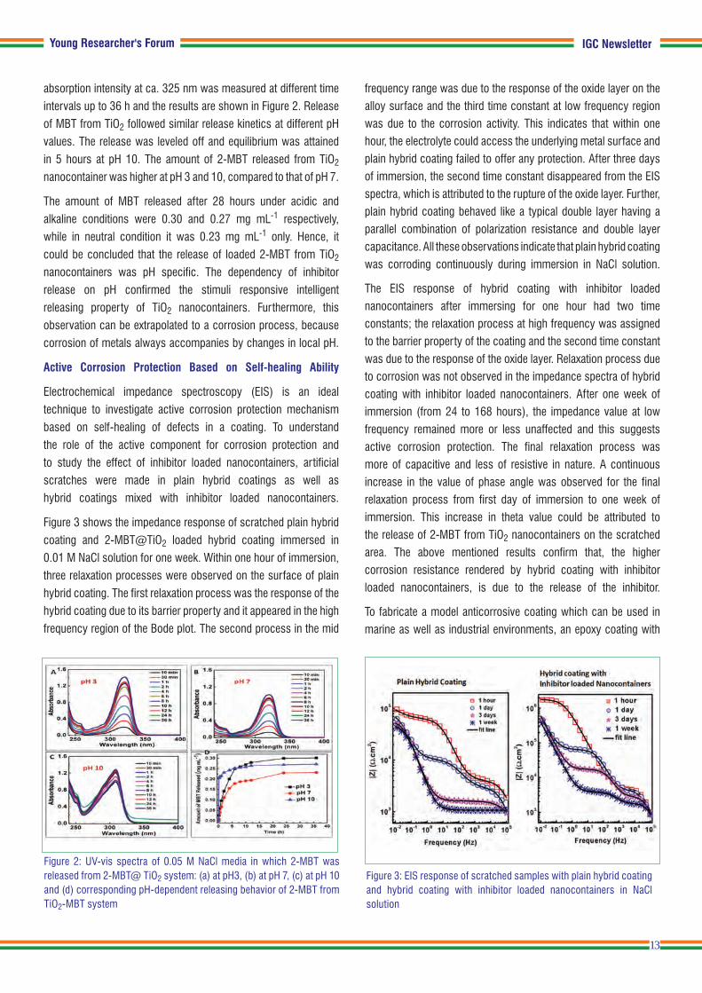
Figure 3 shows the impedance response of scratched plain hybrid
coating and 2-MBT@TiO2 loaded hybrid coating immersed in
0.01 M NaCl solution for one week. Within one hour of immersion,
three relaxation processes were observed on the surface of plain
hybrid coating. The first relaxation process was the response of the
hybrid coating due to its barrier property and it appeared in the high
frequency region of the Bode plot. The second process in the mid
frequency range was due to the response of the oxide layer on the alloy surface and the third time constant at low frequency region was due to the corrosion activity. This indicates that within one hour, the electrolyte could access the underlying metal surface and plain hybrid coating failed to offer any protection. After three days of immersion, the second time constant disappeared from the EIS spectra, which is attributed to the rupture of the oxide layer. Further, plain hybrid coating behaved like a typical double layer having a parallel combination of polarization resistance and double layer capacitance. All these observations indicate that plain hybrid coating was corroding continuously during immersion in NaCl solution.
The EIS response of hybrid coating with inhibitor loaded nanocontainers after immersing for one hour had two time constants; the relaxation process at high frequency was assigned to the barrier property of the coating and the second time constant was due to the response of the oxide layer. Relaxation process due to corrosion was not observed in the impedance spectra of hybrid coating with inhibitor loaded nanocontainers. After one week of immersion (from 24 to 168 hours), the impedance value at low frequency remained more or less unaffected and this suggests active corrosion protection. The final relaxation process was more of capacitive and less of resistive in nature. A continuous increase in the value of phase angle was observed for the final relaxation process from first day of immersion to one week of immersion. This increase in theta value could be attributed to the release of 2-MBT from TiO2 nanocontainers on the scratched area. The above mentioned results confirm that, the higher corrosion resistance rendered by hybrid coating with inhibitor loaded nanocontainers, is due to the release of the inhibitor.
To fabricate a model anticorrosive coating which can be used in marine as well as industrial environments, an epoxy coating with
Figure 3: EIS response of scratched samples with plain hybrid coating and hybrid coating with inhibitor loaded nanocontainers in NaCl solution
Figure 2: UV-vis spectra of 0.05 M NaCl media in which 2-MBT was released from 2-MBT@ TiO2 system: (a) at pH3, (b) at pH 7, (c) at pH 10 and (d) corresponding pH-dependent releasing behavior of 2-MBT from TiO2-MBT system

IGC Newsletter
14
pretreatment layer containing inhibitor loaded titania nanocontainers
was prepared and applied on 9Cr-1Mo ferritic steel. The design
of the epoxy coatings developed for long term corrosion test is
given in Figure 4. The design and the thickness of the coatings
were chosen according to ISO standard EN ISO 129444.
The adhesive property of the epoxy coatings were leveled
according to the ASTM D 3359-09 cross-hatch tape adhesion
test. The plain epoxy coating and epoxy nanocontainer coatings
were ranked as 5A. Both the coatings have perfect adhesion to
the alloy surface. This result also suggests that the addition of the
nanocontainer based pre-treatment layer did not affect the adhesive
property of the epoxy coating. The nanocontainer impregnated
sol-gel hybrid coating acted as adhesion promoter in addition
to imparting active corrosion protection to metallic substrates.
The long term corrosion protection performance of the
coatings was investigated using salt spray test. Both the epoxy
nanocontainer coating and reference plain epoxy coating were
subjected to salt spray test for 1000 hours. Two sets of coated
specimens were exposed to salt spray test. Figure 5 (a and b) show
the photographs of epoxy nanocontainer coating and plain epoxy
coating after 1000 hours of salt spray test. Blistering of the coatings
and under coat corrosion were visible in the case of plain epoxy
coating after 1000 hours of salt spray exposure. Moreover, a small
flake of the coating peeled off from the metallic substrate (Figure
5a). Conversely, no delamination of coatings was observed for
epoxy nanocontainer coating. Insignificant rust markings appeared
on one side in the scratched area of the coating (Figure 5a).
However, in the second set of tested samples, such rust markings
were not observed on the scratched area (Figure 5b). The salt
spray chamber test revealed sufficient protection even after
1000 hours of exposure for inhibitor loaded nanocontainer mixed
epoxy coating compared to that of reference (plain top epoxy)
coating. The salt spray test for epoxy nanocontainer coating was
further continued up to 2000 hours of exposure and the image
of the 2000 hours salt spray exposed specimen is presented in
Figure 5c. It was observed that even after 2000 hours of salt
spray exposure, the coating was intact and significant damage
due to corrosion did not occur on epoxy nanocontainer coating.
Raman Analysis of Salt Spray Exposed Coated Specimens
Raman spectra were recorded for both plain epoxy coating and
epoxy nanocontainer coatings after 1000 hours of salt spray
exposure (Figure 6). The spectra were obtained by focusing the
laser beam on the centre of the “X” cut on the coated surface.
The various phases of iron oxides and iron-oxy hydroxides,
which displayed strong Raman scattering were Lepidocrocite
(γ-FeOOH), Goethite (α-FeOOH), chlorinated oxyhydroxide
Akaganeite (β-FeOOH), Hematite (α-Fe2O3), Maghemite (γ-Fe2O3),
and Magnetite (Fe3O4). The intense Raman lines were observed
at 225, 290, 410, 615 and 1316 cm-1 for plain epoxy coatings.
These Raman lines are characteristic of hematite (α-Fe2O3).
Raman spectra did not reveal the presence of other oxides
or oxyhydroxides of iron, and hematite was the predominant
corrosion product (Figure 6a). Moreover, features for the epoxy
coatings were not observed in the Raman spectra. The Raman
spectra of epoxy nanocontainer coatings did not show any
peak corresponding to the corrosion products (Figure 6b).
The Raman results are in good agreement with the salt spray
Figure 5: Photographs of ENC and reference PEC after 1000 h of exposure to neutral salt spray test: (A) first set; (B) second set; (C) Epoxy Nanocontainer Coating (ENC) after 2000 hours of exposure to neutral salt spray test
Young Researcher's Forum
Figure 4: Design of the epoxy based coatings for long term corrosion test

IGC Newsletter
15
Figure 7: Schematic self healing mechanism: (a) Compact coating (b) Controlled release of inhibitor from the nanocontainer in replay to ive corrosion activity which is accompanied by pH change
(a)
(b)
visual examination results. The major Raman lines corresponding
to the epoxy backbone of the coatings were observed in the
spectra. The peaks at 1188, 1460 and 1610 cm-1 corresponded
to the stretching vibrations of the disubstituted aromatic rings. The
more intense and better resolved Raman line at 1610 cm-1 was
due to the strong stretching of aromatic ring C=C. The breathing
vibration mode of epoxide group appeared at 1234 and 1250 cm-1.
The peaks at 824 and 916 cm-1 would have resulted from the
symmetric deformation of the epoxy ring. Interestingly, the presence
of 2-MBT could be detected in the Raman spectra of ENC confirming
the release of 2-MBT in the scratched area of the coatings. The
Raman lines at 640 and 672 cm-1 may be attributed to –CS
stretching vibration mode. The Raman line at 551 cm-1 probably
corresponded to CNH bending mode. The in-plane ring bending
of benzene ring appeared at 769 cm-1. Thus, the Raman spectra
of epoxy nanocontainer coatings after 1000 hours of salt spray
exposure showed the presence of released 2-MBT at the scratched
area of the coatings and absence of any corrosion products.
Mechanism for Active Corrosion Protection Based on
Self-healing Ability
The initiation of corrosion process itself can trigger the release
of the inhibitor molecules from the nanocontainer. The improved
corrosion protection of the coating can be explained by a
self-healing mechanism. A graphical illustration of the proposed
mechanism is presented in Figure 7. During corrosion, acidic
pH develops around the anodic area and alkaline pH develops at
cathodic area. If any local damage occurs in the coating, corrosion
will instigate in the alloy surface. Localized corrosion of ferritic
steels is commonly accompanied by change in pH at the micro
anodes and micro cathodes. The release of inhibitor molecules into
aqueous NaCl solution occur by diffusion through the channels and
pores of the nanocontainers. The enhanced corrosion resistance
exhibited by the inhibitor loaded nanocontainer mixed hybrid coating
could be explained as follows: as the immersion time increases, the
water molecules and corrosive species enter the coating through
the pores and cracks of the coatings. This electrolyte solution
could infiltrate into the nanocontainers through the mesopores and
the inhibitor molecules could diffuse along this aqueous pathway.
When any corrosion activity takes place, low pH prevails around the
micro anode and alkaline pH develops around the micro cathode area.
This change in local pH will increase the release rate and quantity
of the inhibitor released from the nanocontainers. The anticorrosive
property of the organic inhibitor, 2-mercaptobenzothiazole is
based on producing a film on the alloy surface and this layer
acts as physical barrier to aggressive corrosive ions. When
pitting corrosion is initiated, these organic inhibitor molecules
can form complexes with the metal ions and form a protective
layer and that stops further dissolution of the metal and alloys.
C. Arunchandran and colleagues
Metallurgy and Materials Group
Young Researcher's Forum
Figure 6: Raman spectra of (a) plain epoxy coating and (b) epoxy nanocontainer coating after 1000 hours of salt spray exposure. Inset shows the image of the specimen and the circle indicates the area at which the spectrum was recorded
(a) (b)

IGC Newsletter
16
Delegations from Korea Atomic Energy Research Institute (KAERI) led by Dr. Park Won Seok, Director and Leader of the
KAERI team, visited our Center on February 02, 2016. During their visit, they visited Fast Breeder Test Reactor, Fast Reactor
Technology Group , Sodium Safety related Experimental Facilities and 100 tonne Shake Table.
Delegations from Korea Atomic Energy Research Institute (KAERI) with Dr. S.A.V. Satya Murty, Director, IGCAR during their
visit to the Centre
Visit of Dignitaries
Delegation from Idaho National Laboratory with Dr. A. K. Bhaduri, Director, Metallurgy and Materials Group and senior colleagues of the Centre
Delegation from Idaho National Laboratory led by Dr. Sarah Lennon, Director, Office of Bilateral Cooperation, Office of Nuclear Energy, DOE visited our Centre on February 16, 2016. During their visit, they visited Fast Breeder Test Reactor, KAMINI, Radio Metallurgy Laboratory, Fast Reactor Technology Group, Sodium Safety related Experimental Facilities and 100 Tonne Shake Table.
Visit of Dignitaries

Awards & Honours IGC Newsletter
Awards & Honours
Best Paper/Poster Award
Dr. U. Kamachi Mudali, has been conferred “Meritorious Award 2016” from National Corrosion Council of India, CECRI Dr. B. K. Panigrahi, has been conferred MRSI Medal 2016
Soil Structure Interaction Studies of a Nuclear Facility Structure Supported on Engineering Backfill Shri N. Nitheesh, Shri G. Padmanaban, Ms. Sudipta ChattopadhyayaInternational Conference on Advances i n Civil Engineering and Sustainable Construction organised by SRM University, 30 March – 01 April, 2016Best Paper Award
Visit of Dignitaries
Shri G Srinivasan, former Director, Reactor Operation and Maintenance Group and Reactor Design Group delivered
IGC Colloquium on the topic “Pebbles on the Shore” on February 25, 2016.
Shri G Srinivasan during the IGC Colloquium

Dr. M. Sai Baba, Chairman, Editorial Committee, IGC Newsletter
Editorial Committee Members: Shri M. S. Chandrasekar, Dr. N. V. Chandra Shekar, Dr. T. S. Lakshmi Narasimhan Dr. C. Mallika, Shri V. Rajendran, Dr. Saroja Saibaba, Dr. C. V. Srinivas and Dr. Vidya Sundararajan
Published by Scientific Information Resource Division, IGCAR, Kalpakkam-603102
Common Emigrant