Embed Size (px)
Citation preview

ISPE CASA Energy Management Forum - Energy Management of Capital Projects at NovartisLee Willmon, Head of Health, Safety and EnvironmentVaccines and DiagnosticsHolly Springs, NC16 Sept 10

Agenda
Holly Springs Capital Project Overview
Overview of Energy Standards at Novartis
Capital Project Energy Challenge Review – How we evaluate projects at Novartis
Technical Energy Saving Application - Heat Recovery Chiller
Q&A – 5 minutes
Technical Energy Saving Application – Heat Pipes
Q&A – 5 minutes
If time allows: Technical Energy Saving Application - Chilled Water Plant
2 | ISPE CASA Meeting – Energy at Novartis | Lee Willmon | 16 Sept 2010 | Business Use Only NVDGEN099
Holly Springs Facility Summary
Novartis Vaccines and Diagnostics vaccine manufacturing facilitylocated in Holly Springs, North Carolina
Advanced technologies for flu vaccines• Cell culture instead of conventional technology using fertilized chicken eggs
Designed to manufacture bulk and finished product (pre-filled syringes) for seasonal and pandemic influenza vaccines
3 | ISPE CASA Meeting – Energy at Novartis | Lee Willmon | 16 Sept 2010 | Business Use Only NVDGEN099
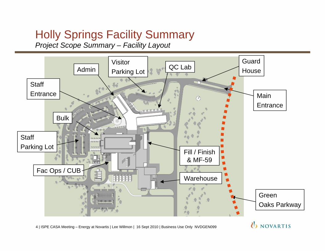
Holly Springs Facility SummaryProject Scope Summary – Facility Layout
QC LabAdmin
Fac Ops / CUB
StaffEntrance
VisitorParking Lot
StaffParking Lot
MainEntrance
GuardHouse
Warehouse
Fill / Finish & MF-59
GreenOaks Parkway
Bulk
4 | ISPE CASA Meeting – Energy at Novartis | Lee Willmon | 16 Sept 2010 | Business Use Only NVDGEN099

Holly Springs Facility SummaryBulk Building Description
Two cell culture lines (3 x 5,000L each)
Two downstream processing (purification) lines
Annual bulk seasonal flu capacity of 50 M doses (trivalent) or 150 M doses (monovalent) within 6 months after declaration of a pandemic
Media preparation, buffer charging and equipment preparation
Designed for BSL2+, capable to upgrade to BSL3
Dedicated decon autoclaves for solid waste and biowaste inactivation for liquid waste
Locker rooms to support bulk operations
5 | ISPE CASA Meeting – Energy at Novartis | Lee Willmon | 16 Sept 2010 | Business Use Only NVDGEN099

Holly Springs Facility SummaryFill Finish Building Description
One 350L scale MF59 adjuvant line*
One 1200L Formulation Suite
One pre-filled syringe line• Utilizes isolator technology• E-beam used for
decontaminating tubs of syringes• Automated inspection machine• Packaging equipment including
labeler and cartoner
Supporting equipment preparation
6 | ISPE CASA Meeting – Energy at Novartis | Lee Willmon | 16 Sept 2010 | Business Use Only NVDGEN099
* MF59 is not currently included in any US approved vaccines

Holly Springs Facility SummaryQC Laboratory/ Administrative Building Description
QC Laboratory wing includes microbiology, chemistry, biochemistry and virology labs
Supporting glass wash and autoclave areas
Dedicated decon autoclaves for solid waste and biowaste inactivation for liquid waste
Designed with BSL3 capability in Sterility, PCR and Virology
Administrative wing includes 90 work stations, cafeteria, and training rooms
7 | ISPE CASA Meeting – Energy at Novartis | Lee Willmon | 16 Sept 2010 | Business Use Only NVDGEN099
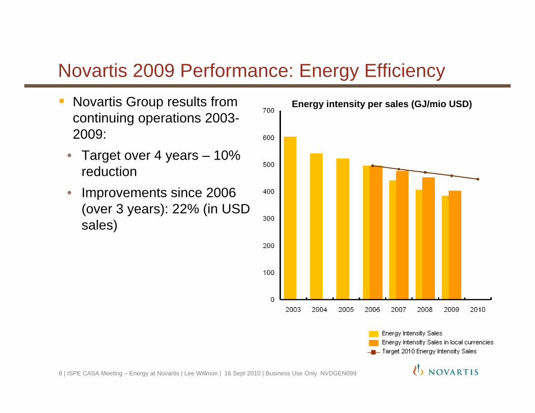
Novartis 2009 Performance: Energy EfficiencyEnergy intensity per sales (GJ/mio USD)Novartis Group results from
continuing operations 2003-2009:
• Target over 4 years – 10% reduction
• Improvements since 2006 (over 3 years): 22% (in USD sales)
8 | ISPE CASA Meeting – Energy at Novartis | Lee Willmon | 16 Sept 2010 | Business Use Only NVDGEN099

Novartis Corporate Energy Standards (Guidelines)
Apply to all Novartis sites, worldwide
Guideline 13 – Energy management at Novartis• Site energy manager• Site auditing and reporting• Checklists and indexes• Energy challenge of capital projects (review prior to approval)
Guideline 14 – Energy Standards for Buildings and Equipment• Building efficiency requirements• Technical specifications for buildings, equipment and refrigerants
9 | ISPE CASA Meeting – Energy at Novartis | Lee Willmon | 16 Sept 2010 | Business Use Only NVDGEN099

HSE Corporate Guideline 13Objectives of the Energy Challenge of Capital Projects
HSE Guideline 13 provides information on what to consider, who to involve and how to proceed
Capital Appropriation Request (CAR) requires that aspects of HSE and energy conservation are considered in capital projects
The Energy Manager/HSE is involved at the conceptual design and at each stage of the project
The energy challenge should consider the size and circumstances of the investment project: comprehensive, simplified or rapid
The total cost of ownership (investment and operational cost) are taken into account as basis for a decision
Energy projects are allowed to pay back over the life of the asset
10 | ISPE CASA Meeting – Energy at Novartis | Lee Willmon | 16 Sept 2010 | Business Use Only NVDGEN099
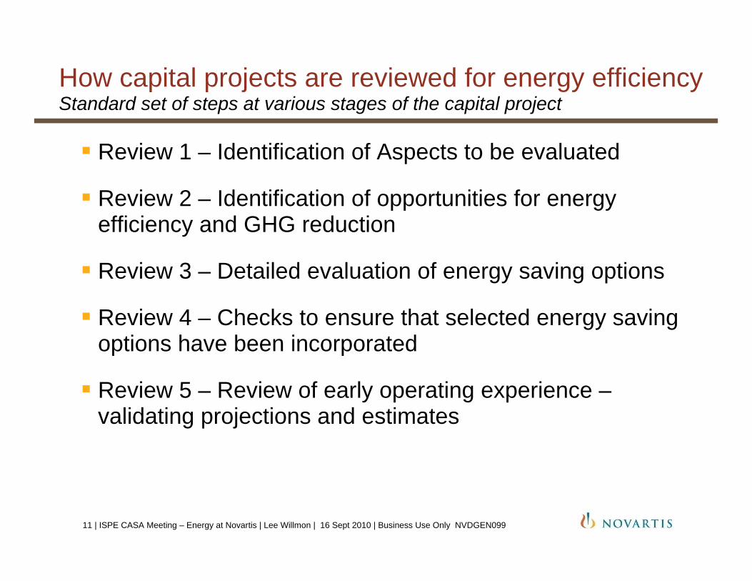
How capital projects are reviewed for energy efficiencyStandard set of steps at various stages of the capital project
Review 1 – Identification of Aspects to be evaluated
Review 2 – Identification of opportunities for energy efficiency and GHG reduction
Review 3 – Detailed evaluation of energy saving options
Review 4 – Checks to ensure that selected energy saving options have been incorporated
Review 5 – Review of early operating experience –validating projections and estimates
11 | ISPE CASA Meeting – Energy at Novartis | Lee Willmon | 16 Sept 2010 | Business Use Only NVDGEN099

Operation Management
Procurement(QAD 507.0014)
Conceptual Design (CD)
Project Life Cycle
Revi
ew I
Rev
iew
II
Revi
ew II
I
Revi
ew V
Basic Design (BD)
Detail Engineering
(DE)
Realization / Construction
Comm. and Handover
Revi
ew IV
Project energy challenging process according to CHSE Guidance Note 13.3
12 | ISPE CASA Meeting – Energy at Novartis | Lee Willmon | 16 Sept 2010 | Business Use Only NVDGEN099
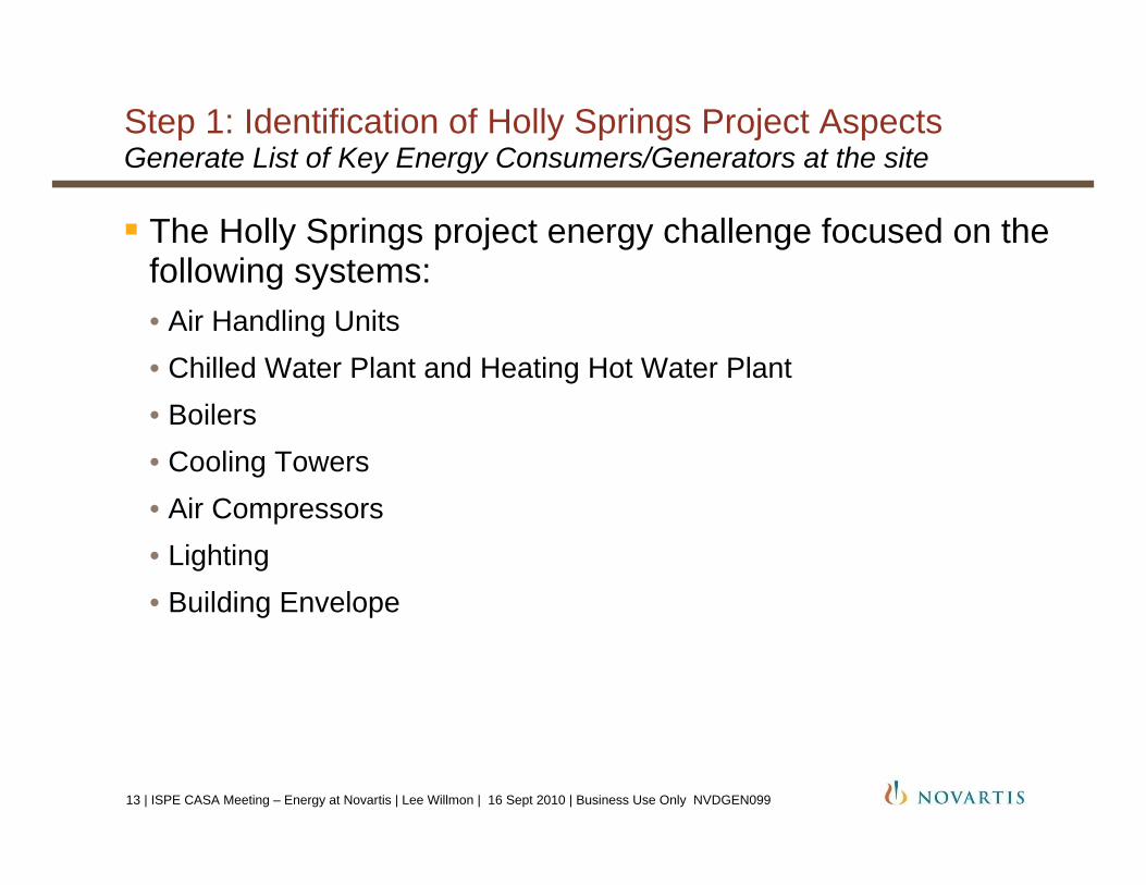
Step 1: Identification of Holly Springs Project AspectsGenerate List of Key Energy Consumers/Generators at the site
The Holly Springs project energy challenge focused on the following systems:• Air Handling Units• Chilled Water Plant and Heating Hot Water Plant• Boilers• Cooling Towers• Air Compressors• Lighting • Building Envelope
13 | ISPE CASA Meeting – Energy at Novartis | Lee Willmon | 16 Sept 2010 | Business Use Only NVDGEN099
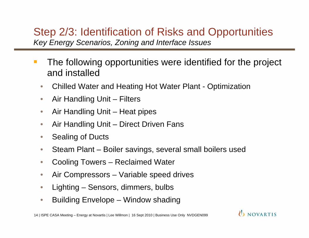
Step 2/3: Identification of Risks and OpportunitiesKey Energy Scenarios, Zoning and Interface Issues
The following opportunities were identified for the project and installed
• Chilled Water and Heating Hot Water Plant - Optimization• Air Handling Unit – Filters• Air Handling Unit – Heat pipes• Air Handling Unit – Direct Driven Fans• Sealing of Ducts• Steam Plant – Boiler savings, several small boilers used• Cooling Towers – Reclaimed Water• Air Compressors – Variable speed drives• Lighting – Sensors, dimmers, bulbs • Building Envelope – Window shading
14 | ISPE CASA Meeting – Energy at Novartis | Lee Willmon | 16 Sept 2010 | Business Use Only NVDGEN099

Step 4/5: Systems Installed and Data Collected
Evaluation Currently Underway
Building Automation System evaluation
System optimization and commissioning• About 50% complete
Metering and data collection opportunities still exist
15 | ISPE CASA Meeting – Energy at Novartis | Lee Willmon | 16 Sept 2010 | Business Use Only NVDGEN099

Heat Recovery Chiller SystemAlexander Mitrovic, PE, CEANovartis, Holly Springs, NC, September 2010
ISPE-CASA Energy Management Forum

Heat Recovery Chiller System
Basic principle of HRC system• Recover waste heat from chillers for HVAC heating
- Avoid steam usage
• Increase total efficiency of chilled/heating water plant- Select design with lowest life cycle cost- Lower our cost of goods at the Holly Springs site
• Reduce overall consumption of resources- Natural Gas, and therefore CO2 emissions- Water savings from cooling tower and boiler make-up- Chemical treatment of water
17 | ISPE CASA Meeting – Energy at Novartis | Lee Willmon | 16 Sept 2010 | Business Use Only NVDGEN099

Heat Recovery Chiller System
Design details• One 800-ton heat recovery chiller, with constant volume pumps• Supplies 135 °F water to heating hot water system, and 40 °F water to
chilled water system• HRC is not piped to cooling tower. All heat must be rejected to the
HHW loop. Minimum turndown of 30%• COP (Coefficient of Performance) is increased since chiller is
simultaneously heating and cooling
COP = Useful workInput work The Bigger
The Better!18 | ISPE CASA Meeting – Energy at Novartis | Lee Willmon | 16 Sept 2010 | Business Use Only NVDGEN099

Heat Recovery Chiller System
| Heat Recovery Chiller System | Alexander Mitrovic, PE, CEA | 18 Sep 2010 | ISPE CASA Energy Forum19

Heat Recovery Chiller System
40°F
105°F 135°F
Condenser
Variable °F
Water Heater135°F
Condensate60# steam
(3) 1350 Ton Chillers
Hot water loop
Chilled water loop
Heat RecoveryChiller
55°F
Evaporator
20 | ISPE CASA Meeting – Energy at Novartis | Lee Willmon | 16 Sept 2010 | Business Use Only NVDGEN099

Heat Recovery Chiller System
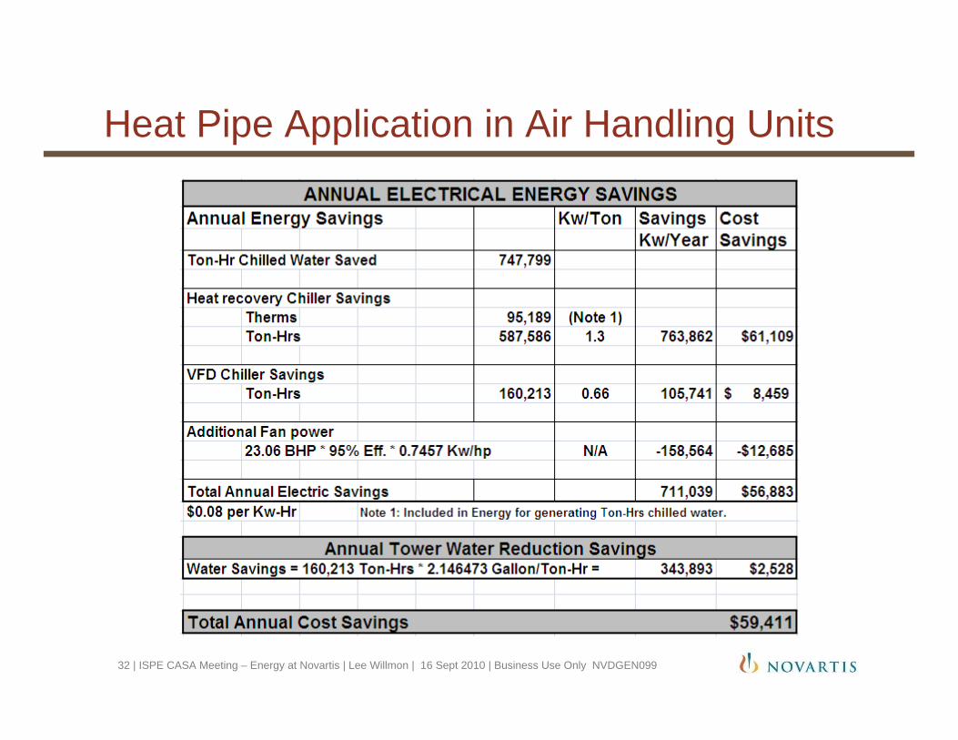
What were the major achievements, impacts, benefits?• Annual calculated savings of:
- $750,000 in utility bills- 7,240 tons CO2 emissions- 13,724,000 gallons water- Chemical treatment of water
• Simple payback of 15 months• Sidecar arrangement does not impact CHW plant• Boilers are not needed to provide HHW for site, but are ready as a
standby heating source during HRC servicing or failure
21 | ISPE CASA Meeting – Energy at Novartis | Lee Willmon | 16 Sept 2010 | Business Use Only NVDGEN099
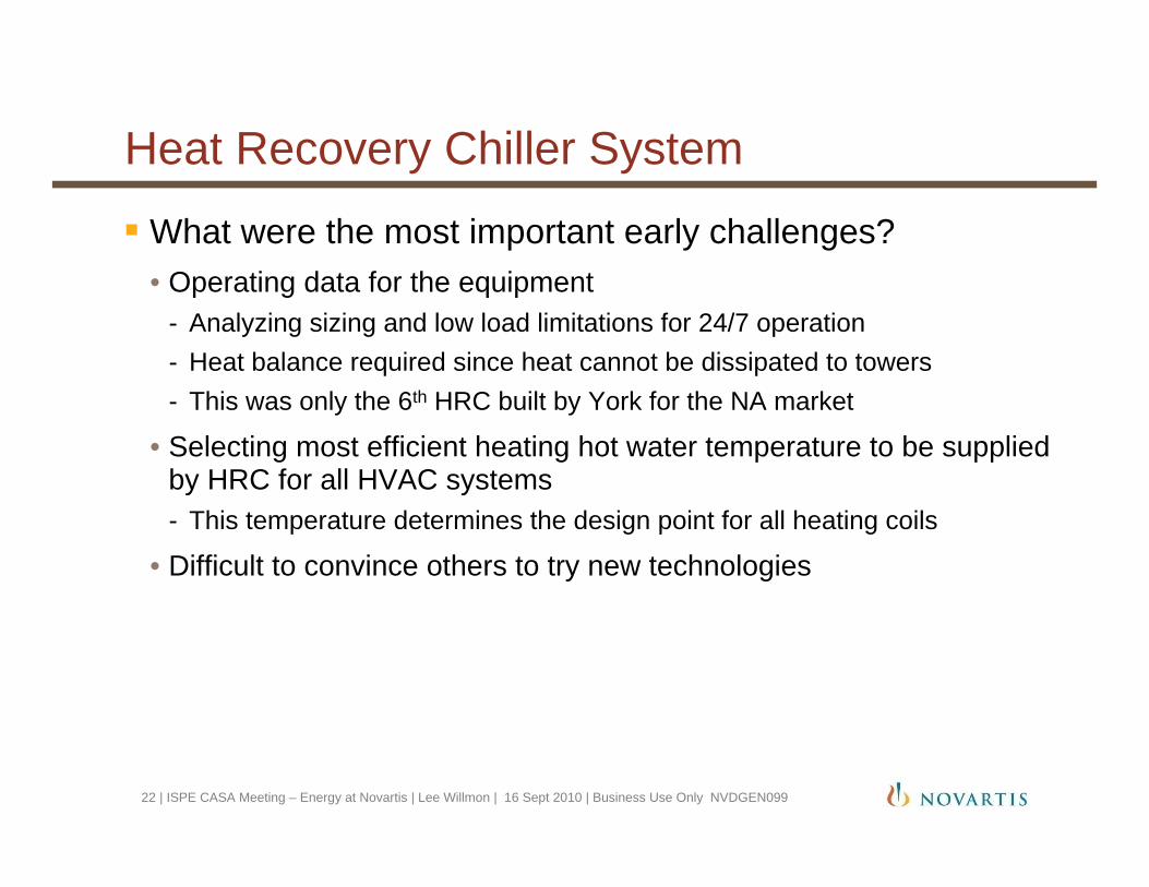
Heat Recovery Chiller System
What were the most important early challenges?• Operating data for the equipment
- Analyzing sizing and low load limitations for 24/7 operation - Heat balance required since heat cannot be dissipated to towers- This was only the 6th HRC built by York for the NA market
• Selecting most efficient heating hot water temperature to be supplied by HRC for all HVAC systems- This temperature determines the design point for all heating coils
• Difficult to convince others to try new technologies
22 | ISPE CASA Meeting – Energy at Novartis | Lee Willmon | 16 Sept 2010 | Business Use Only NVDGEN099

Heat Recovery Chiller System
Implementation issues:• Since Holly Springs was a green field site, there was no load during
start-up of equipment. A 1000 ton rental plate and frame heat exchanger was installed to provide a false load.
• We were unable to simulate low load conditions, so the HRC was only tuned for maximum load.
• These issues were discovered when HRC was operating at minimum load. Local chiller service group was unable to troubleshoot and needed support from corporate engineering.
• Two parameters were modified and machine ran fine.• Power issues continue to cause issues with communications
between starter and HRC.
23 | ISPE CASA Meeting – Energy at Novartis | Lee Willmon | 16 Sept 2010 | Business Use Only NVDGEN099

ISPE-CASA Energy Management Forum
Thank you for your interest in our heat recovery chiller!
Any questions?
24 | ISPE CASA Meeting – Energy at Novartis | Lee Willmon | 16 Sept 2010 | Business Use Only NVDGEN099

Heat Pipe Application in Air Handling UnitsAlexander Mitrovic, PE, CEANovartis, Holly Springs, NC, September 2010
ISPE-CASA Energy Management Forum
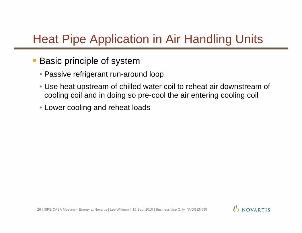
Heat Pipe Application in Air Handling Units
Basic principle of system• Passive refrigerant run-around loop• Use heat upstream of chilled water coil to reheat air downstream of
cooling coil and in doing so pre-cool the air entering cooling coil • Lower cooling and reheat loads
26 | ISPE CASA Meeting – Energy at Novartis | Lee Willmon | 16 Sept 2010 | Business Use Only NVDGEN099

Heat Pipe Application in Air Handling Units
27 | ISPE CASA Meeting – Energy at Novartis | Lee Willmon | 16 Sept 2010 | Business Use Only NVDGEN099
Heat Pipe Application in Air Handling Units
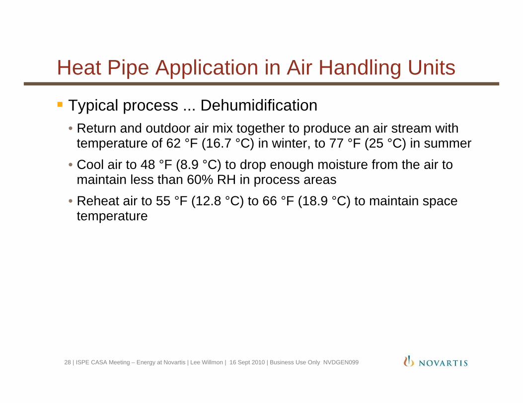
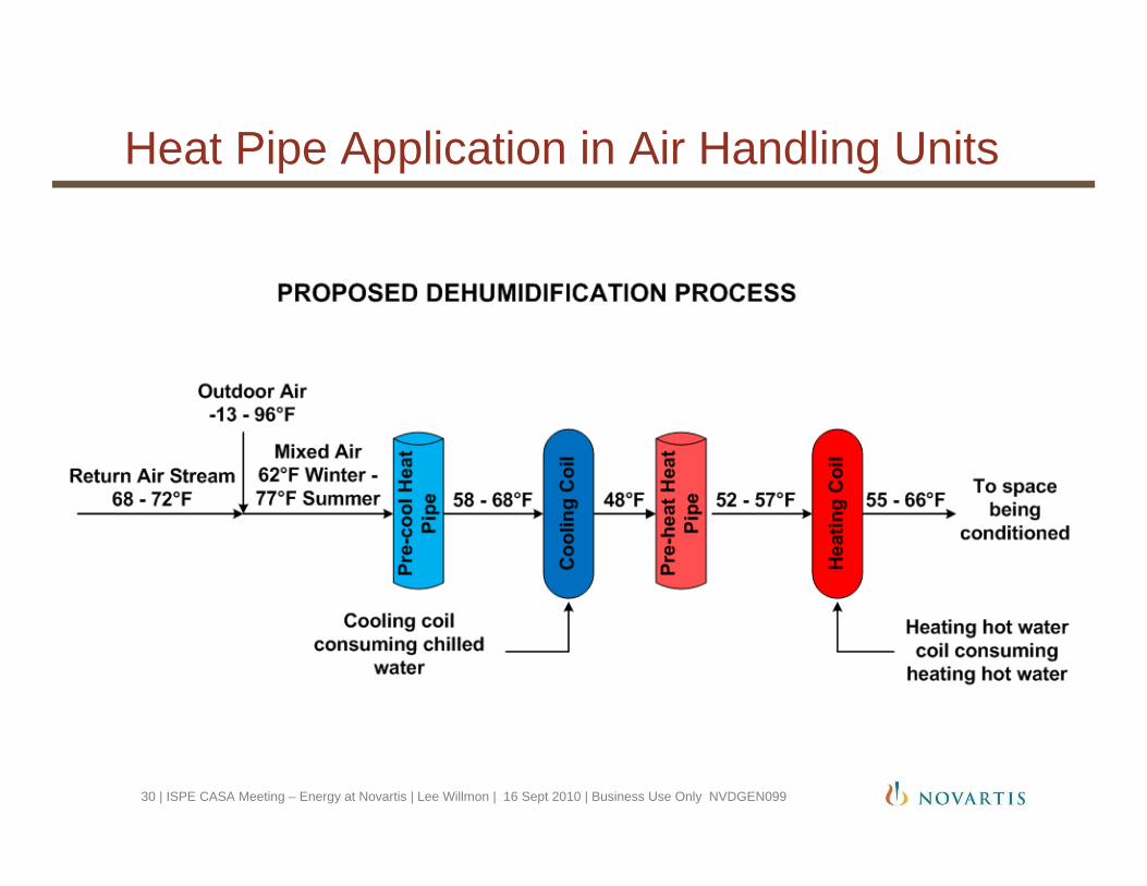
Typical process ... Dehumidification• Return and outdoor air mix together to produce an air stream with
temperature of 62 °F (16.7 °C) in winter, to 77 °F (25 °C) in summer • Cool air to 48 °F (8.9 °C) to drop enough moisture from the air to
maintain less than 60% RH in process areas• Reheat air to 55 °F (12.8 °C) to 66 °F (18.9 °C) to maintain space
temperature
28 | ISPE CASA Meeting – Energy at Novartis | Lee Willmon | 16 Sept 2010 | Business Use Only NVDGEN099

Heat Pipe Application in Air Handling Units
29 | ISPE CASA Meeting – Energy at Novartis | Lee Willmon | 16 Sept 2010 | Business Use Only NVDGEN099
Heat Pipe Application in Air Handling Units
30 | ISPE CASA Meeting – Energy at Novartis | Lee Willmon | 16 Sept 2010 | Business Use Only NVDGEN099

Heat Pipe Application in Air Handling Units
Payback analysis factors• First cost of heat pipe• Additional maintenance of heat pipe• Added first cost due to larger fan HP requirement• Energy saved on reduced cooling coil load• Energy saved on reduced reheat coil load• Added energy cost of running fans at higher BHP
Payback period• Retrofit applications typically 3+ years• New equipment application typically 2-3 years
31 | ISPE CASA Meeting – Energy at Novartis | Lee Willmon | 16 Sept 2010 | Business Use Only NVDGEN099
Heat Pipe Application in Air Handling Units
32 | ISPE CASA Meeting – Energy at Novartis | Lee Willmon | 16 Sept 2010 | Business Use Only NVDGEN099
Heat Pipe Application in Air Handling Units
Implementation issues:• The pre-cooling coils were installed with a standard depth drain pan,
but the fins are horizontal, so there was minor condensate carryover on high humidity days- Mist eliminators are being assessed- Typical heat pipe installation leaves no space between the cooling coils
and heat pipe coils, so condensate carryover is not an issue- However, we designed service access between coil sections for
maintainability, so this causes potential for carryover
• Minor issues with control valves which were immediately resolved• Early coordination issue with three AHUs placed heat pipe coils in
different AHU sections. Intent was to locate cooling coil and heat pipe coils in same AHU section so that heat pipes could be pre-piped in heat pipe manufacturers facility. - This required more field time than expected
33 | ISPE CASA Meeting – Energy at Novartis | Lee Willmon | 16 Sept 2010 | Business Use Only NVDGEN099

ISPE-CASA Energy Management Forum
Thank you for your interest in our heat pipe application!
Any questions?
34 | ISPE CASA Meeting – Energy at Novartis | Lee Willmon | 16 Sept 2010 | Business Use Only NVDGEN099

Variable Primary Flow Chilled Water PlantAlexander Mitrovic, PE, CEANovartis, Holly Springs, NC, September 2010
ISPE-CASA Energy Management Forum
Variable Primary Flow Chilled Water Plant
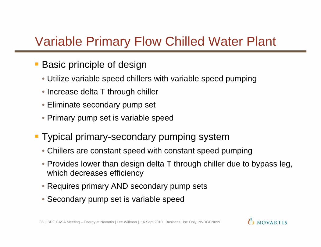
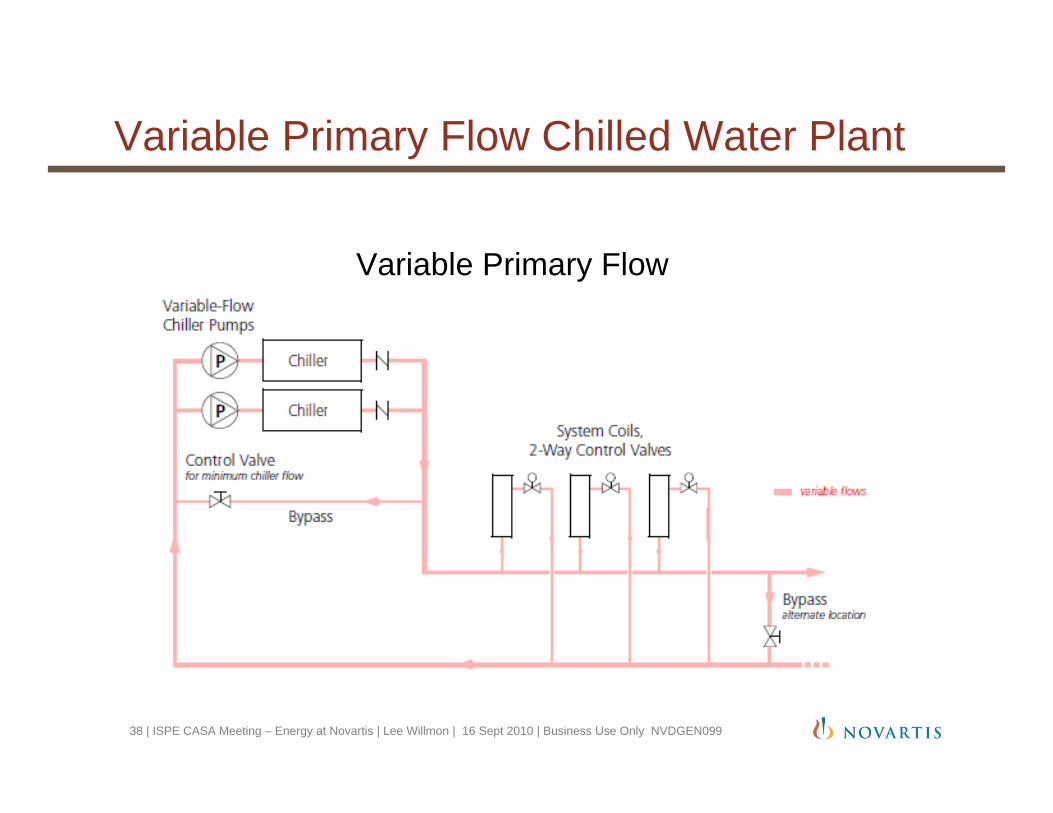
Basic principle of design• Utilize variable speed chillers with variable speed pumping• Increase delta T through chiller• Eliminate secondary pump set• Primary pump set is variable speed
Typical primary-secondary pumping system• Chillers are constant speed with constant speed pumping• Provides lower than design delta T through chiller due to bypass leg,
which decreases efficiency• Requires primary AND secondary pump sets• Secondary pump set is variable speed
36 | ISPE CASA Meeting – Energy at Novartis | Lee Willmon | 16 Sept 2010 | Business Use Only NVDGEN099

Variable Primary Flow Chilled Water Plant
37 | ISPE CASA Meeting – Energy at Novartis | Lee Willmon | 16 Sept 2010 | Business Use Only NVDGEN099
Traditional Primary-Secondary Pumping
Variable Primary Flow Chilled Water Plant
38 | ISPE CASA Meeting – Energy at Novartis | Lee Willmon | 16 Sept 2010 | Business Use Only NVDGEN099
Variable Primary Flow
Variable Primary Flow Chilled Water Plant
Advantages of Variable Primary Flow• Lower first cost• Less pumping energy• Less floor space and potentially lower building cost
Disadvantages of Variable Primary Flow• More complex controls compared to primary-secondary systems
Best applications for Variable Primary Flow• Industrial plants with high base load and multiple chillers• Plants with sophisticated design engineers and utility operators that
understand the controls
39 | ISPE CASA Meeting – Energy at Novartis | Lee Willmon | 16 Sept 2010 | Business Use Only NVDGEN099
Variable Primary Flow Chilled Water Plant
Implementation issues• Staging of chillers was tricky. Initial control sequence was too
cumbersome and was later simplified.- Overflow running chillers during stage up to avoid tripping
• Need to deliver 40+/- 2 °F water for process requirements, so staging of chillers needs to hold this requirement- Set point was lowered during chiller staging
• Plant cannot be run in manual, so utility operator training withcontinual reinforcement is required
• Power quality issues in Holly Springs area - Modified internal chiller controls to prevent nuisance trips- Rapid restart algorithm so chillers can be brought back online quickly
40 | ISPE CASA Meeting – Energy at Novartis | Lee Willmon | 16 Sept 2010 | Business Use Only NVDGEN099

ISPE-CASA Energy Management Forum
Thank you for your interest in our energy program!
Any questions about...• Heat recovery chiller?• Heat pipes?• Variable primary flow?
41 | ISPE CASA Meeting – Energy at Novartis | Lee Willmon | 16 Sept 2010 | Business Use Only NVDGEN099


![ISPE-KC [October 2011]](https://img.dokumen.tips/doc/110x75/55854765d8b42ae15d8b4bf8/ispe-kc-october-2011.jpg)